Balluff C0405 Cobalt HF RFID Reader User Manual C0405 Operator s Manual
BALLUFF inc Cobalt HF RFID Reader C0405 Operator s Manual
Balluff >
User Manual


scort Memory Systems reserves the right to make modifications and
improvements to its products and/or documentation without prior notification.
Escort Memory Systems shall not be liable for technical or editorial errors or
omissions contained herein, nor for incidental or consequential damages resulting
from the use of this material.
The text and graphic content of this publication may be used, printed and distributed
only when all of the following conditions are met:
§ Permission is first obtained from Escort Memory Systems.
§ The content is used for non-commercial purposes only.
§ Copyright information is clearly displayed: Copyright © 2007, Escort Memory
Systems, All Rights Reserved.
§ The content is not modified.
The following are trademarks and/or registered trademarks of Escort Memory
Systems, a Datalogic Group Company: Escort Memory Systems®, the Escort
Memory Systems logo, Subnet16™ and RFID AT WORK™.
Third party product names mentioned herein are used for identification purposes only
and may be trademarks and/or registered trademarks of their respective companies:
Philips, Rockwell Automation, Texas Instruments, Infineon, Belden and Microsoft.
ESCORT MEMORY SYSTEMS
Cobalt C0405-Series
C0405-XXX-01 RFID Controller - Operators Manual
For C0405-Series RFID Controllers
Publication P/N: 17-1328 REV 02 (08/07)
COPYRIGHT © 2007 ESCORT MEMORY SYSTEMS, ALL RIGHTS RESERVED, PUBLISHED IN USA.
E
For C0405 models:
•C0405-232-01
•C0405-485-01
•C0405-USB-01
ESCORT MEMORY SYSTEMS
COBALT C0405-SERIES
RFID CONTROLLERS
High Frequency, Multi-Protocol, Passive RFID Controllers
OPERATORSMANUAL
How to Install, Configure and Operate
Cobalt C0405-Series RFID Controllers
REGULATORY COMPLIANCE -PENDING
FCC PART 15.105
This equipment has been tested and found to comply with the limits for a Class B
digital device, pursuant to part 15 of the FCC Rules. These limits are designed to
provide reasonable protection against harmful interference in a residential installation.
This equipment uses, generates, and can radiate radio frequency energy and, if not
installed and used in accordance with these instructions, may cause harmful
interference to radio communications. However, there is no guarantee that
interference will not occur in a particular installation. If this equipment does cause
harmful interference to radio or television reception, which can be determined by
turning the equipment off and on, the user is encouraged to try to correct the
interference by one or more of the following measures:
• Reorient or relocate the receiving antenna.
• Increase the separation between the equipment and receiver.
• Connect the equipment into an outlet on a circuit different from that to which
the receiver is connected.
• Consult the dealer or an experienced radio/TV technician for help.
FCC PART 15.21
Users are cautioned that changes or modifications to the unit not expressly approved
by Escort Memory Systems may void the user’s authority to operate the equipment.
This device complies with Part 15 of the FCC Rules. Operation is subject to the
following two conditions: (1) This device may not cause harmful interference, and (2)
this device must accept any interference that may cause undesired operation.”
This product complies with CFR Title 21 Part 15.225.
CE
This product complies with the following regulatory specifications: EN-300-330, EN-
300-683, EN 60950, IEC 68-2-1, IEC 68-2-6, IEC 68-2-27 and IEC 68-2-28.
TELEC
This product complies with TELEC Regulations for Enforcement of the Radio Law
Article 6, section 1, No. 1. Cert #: (PENDING)

CONTENTS
P/N: 17-1328 REV 02 (08/07) PAGE 5 OF 83
CONTENTS
CONTENTS .................................................................................... 5
LIST OF TABLES................................................................................................8
LIST OF FIGURES ..............................................................................................9
CHAPTER 1: GETTING STARTED ................................................10
1.1 INTRODUCTION........................................................................................10
1.1.1 Company Background ................................................................................................10
1.1.2 The C0405-Series RFID Controller ............................................................................. 10
1.1.3 C0405 RFID Controller Features.................................................................................11
1.1.4 Abou t th is Manu al.......................................................................................................11
1.1.5 HEX Notation..............................................................................................................12
1.1.6 Contents of the C0405 Product Package ....................................................................12
1.1.7 Us er Su pp lied Compone nts........................................................................................13
1.2 COMMUNICATION OPTIONS .......................................................................14
1.2.1 Connection and Communication Interface Options......................................................14
1.2.2 C0405 Controllers - Interface Connectors ...................................................................14
CHAPTER 2: INSTALLING THE C0405..........................................15
2.1 PREPARING FOR INSTALLATION.................................................................15
2.1.1 Installation Guidelines.................................................................................................15
2.1.2 C0 40 5 Co ntroller D imens ions.....................................................................................16
2.1.3 Mounting the Contro ller...............................................................................................17
2.1.4 Proximity to Metal.......................................................................................................18
2.2 INSTALLING THE C0405-232-01 CONTROLLER............................................19
2.2.1 Steps to Install the C0405-232-01...............................................................................19
2.2.2 C0405-232-01 Cabling Inform ation ................ ........ ................ ................ ........ .............20
2.3 INSTALLING THE C0405-485-01 CONTROLLER............................................22
2.3.1 Steps to Install the C0405-485-01...............................................................................22
2.3.2 C0405-485-01 Cabling Inform ation ................ ........ ................ ................ ........ .............23
2.4 INSTALLING THE C0405-USB-01 CONTROLLER ..........................................24
2.4.1 Steps to Install the C0405-USB-01..............................................................................24
2.4.2 C0405-USB-01 Cabling Inform ation........ ........ ........ ........ ........ ........ ........ ........ ........ ....25
2.5 ANTENNA ENVIRONMENT..........................................................................26
2.5.1 Typical Read Range - Front View* for SLi 54x86mm RFID Tags .................................26
2.5.2 Typical Read Range - Side Profile* for SLi 54x86mm RFID Tags................................27
2.5.3 Typical Read Range - Front View* for HMS / Mifare RFID Tags..................................28
2.5.4 Typical Read Range - Side Profile* for HMS / Mifare RFID Tags.................................29
2.5.5 C0405 Antenna to EMS Tag Ranges ..........................................................................30
CHAPTER 3: POWER & COMMUNICATION...................................31
3.1 POWER REQUIREMENTS ...........................................................................31
3.1.1 C0405-232-01/C0405-485-01 Power Requirements....................................................31
3.1.2 C0405-USB-01 Power Requirements.... ....... .............. .............. .............. .............. .......31

CONTENTS
P/N: 17-1328 REV 02 (08/07) PAGE 6 OF 83
3.2 HF-SERIES CONFIGURATION TAG..............................................................32
3.2.1 Co nfigura tion Tag Over view........................................................................................32
3.2.2 Configuration Tag Memory Map.................................................................................. 33
3.2.3 Using the Configuration Tag .......................................................................................33
CHAPTER 4: LED STATUS ..........................................................35
4.1 LED FUNCTIONS OVERVIEW .....................................................................35
4.1.1 LED Descriptions........................................................................................................36
4.1.2 C0 405- 23 2 LED Status...............................................................................................37
4.1.3 C0 405- USB LED Status ..............................................................................................37
4.1.4 C0 405- 48 5 LED Status...............................................................................................38
4.2 SPECIAL LED OPERATION FUNCTIONS.......................................................40
4.2.1 Updating the Controller’s Firmware.............................................................................40
4.2.2 Continuous Read Mode – LED Behavior.....................................................................41
4.3 LED DISPLAYED ERROR CODES ...............................................................42
CHAPTER 5: RFID TAGS .............................................................43
5.1 RFID TAG OVERVIEW ..............................................................................43
5.1.1 RFID Standards.......................................................................................................43
5.2 EMS RFID TAGS ....................................................................................45
5.2.1 HMS-Series Tags .......................................................................................................45
5.2.2 LRP-Series Tags ........................................................................................................46
5.3 TAG EMBODIMENTS .................................................................................47
5.3.1 Printed Circuit Board RFID Tags.................................................................................47
5.3.2 Molded RFID Tags .....................................................................................................47
5.4 TAG MEMORY .........................................................................................48
5.4.1 Mapp ing Tag Memory.................................................................................................48
5.4.2 Creating an RFID Tag Memory Map ...........................................................................48
5.4.3 Opt im iz ing Tag Me mory..............................................................................................49
CHAPTER 6: COMMAND PROTOCOLS.........................................51
6.1 ABXCOMMAND PROTOCOL OVERVIEW ......................................................51
6.1.1 ABx Command Structures ........................ ........................................ ..........................52
6.1.2 ABx Protocols - Headers and Terminators ..................................................................52
6.1.3 AB x Res po ns e Stru cture s...........................................................................................52
6.2 ABXFAST COMMAND PROTOCOL..............................................................53
6.2.1 ABx Fast - Command / Response Procedure..............................................................53
6.2.2 ABx Fast - Command Packet Structure.......................................................................54
6.2.3 ABx Fast - Response Packet Structure.......................................................................55
6.2.4 ABx Fast - Command Packet Parameters...................................................................56
6.3 ABXSTANDARD COMMAND PROTOCOL......................................................58
6.3.1 ABx Standard - Command Packet Structure ...............................................................59
6.3.2 ABx Standard - Response Packet Structure................................................................59
6.3.3 ABx Standard - Command Example............................................................................60
CHAPTER 7: RFID COMMANDS AND ERROR CODES ...................61
7.1 ABXFAST RFID COMMAND TABLE............................................................61

CONTENTS
P/N: 17-1328 REV 02 (08/07) PAGE 7 OF 83
7.2 ABXSTANDARD RFID COMMAND TABLE ...................................................63
7.3 ERROR CODES ....................................................................................64
7.4 ABXERROR CODE TABLE........................................................................65
7.5 ABXFAST ERROR RESPONSE STRUCTURE.................................................66
7.6 ABXSTANDARD ERROR RESPONSE STRUCTURE.........................................67
APPENDIX A: TECHNICAL SPECIFICATIONS................................68
APPENDIX B: MODELS & ACCESSORIES .....................................70
EMS HARDWARE ............................................................................................70
C0405- Series RFID Co ntro llers ..............................................................................................70
Subnet16™ Gateway Interface Modules................................................................................70
Subnet16™ Hub Interface Modules ....................................................................................... 70
SOFTWARE & DEMONSTRATION KITS.................................................................71
Software Applications............................................................................................................71
Demonstration Kits ................................................................................................................71
CABLE AND NETWORK ACCESSORIES ................................................................72
Power Supplies .....................................................................................................................73
Escort Memory Systems’ RFID Tags .....................................................................................73
APPENDIX C: NETWORK DIAGRAMS ...........................................74
7.6.1 Subnet16 Gateway – ThickNet Network Diagram .....................................................75
7.6.2 Subnet16 Gateway – ThinNet Network Diagram.......................................................76
7.6.3 Subnet16 Hub – Network Diagram ...........................................................................77
APPENDIX D: ASCII CHART .........................................................78
APPENDIX E: RFID TERMINOLOGY..............................................80
EMS WARRANTY ..........................................................................83

CONTENTS
P/N: 17-1328 REV 02 (08/07) PAGE 8 OF 83
LIST OF TABLES
Table 1-1: C0405 Product Package Contents List................................................................12
Table 1-2: Connection and Communication Interface Options..............................................14
Table 1-3: C0405 Controllers - Interface Connectors...........................................................14
Table 2-1: C0405-232-01 Interface Connector – Pinout.......................................................20
Table 2-2: C0405-485-01 Interface Connector - Pinout........................................................23
Table 2-3: C0405-USB-01 Interface Connector - Pinout.......................................................25
Table 2-4: C0405 Antenna to EMS Tag Ranges..................................................................30
Table 3-1: EMS Power Supplies..........................................................................................31
Table 3-3: Configuration Tag - Controller Defaults...............................................................33
Table 4-1: Continuous Read Mode - LED Behavior .............................................................41
Table 5-1: Tag Memory Map Example.................................................................................49
Table 6-1: ABx Protocols - Headers and Terminators..........................................................52
Table 6-2: ABx Fast - Command Packet Structure...............................................................54
Table 6-3: ABx Fast - Response Packet Structure...............................................................55
Table 6-4: ABx Standard - Command Packet Structure .......................................................59
Table 6-5: ABx Standard - Response Packet Structure........................................................59
Table 7-1: ABx Fast RFID Command Table.........................................................................62
Table 7-2: ABx Standard RFID Command Table .................................................................63
Table 7-3: ABx Error Codes ................................................................................................65
Table 7-4: ABx Fast - Error Response Structure..................................................................66
Table 7-5: ABx Standard - Error Response Structure...........................................................67

CONTENTS
P/N: 17-1328 REV 02 (08/07) PAGE 9 OF 83
LIST OF FIGURES
Figure 1-1: C0405 Package Contents Diagram....................................................................13
Figure 2-1: C0405 RFID Controller Dimensions...................................................................16
Figure 2-2: C0405 Controller Attached to Bracket with Cable Connected.............................17
Figure 2-3: C0405 Proximity to Metal...................................................................................18
Figure 2-4: RS232 Interface Cable Schematic.....................................................................21
Figure 2-5: CBL-1493 Connector......................................................................................... 21
Figure 2-6: Typical Read Range - Front View* for SLi 54x86mm Tags.................................26
Figure 2-7: Typical Read Range - Side Profile* for SLi 54x86mm Tags................................27
Figure 2-8: Typical Read Range - Front View* for HMS / Mifare Tags..................................28
Figure 2-9: Typical Read Range - Side Profile* for HMS / Mifare Tags.................................29
Figure 3-1: Cobalt HF Configuration Tag.............................................................................32
Figure 5-1: HMS125HT and HMS150HT tags......................................................................45
Figure 5-2: LRP-Series Tags............................................................................................... 46
Figure 5-3: Optimizing Tag Memory ....................................................................................50
Figure 6-1: ABx Fast - Command Packet Structure .............................................................53
Figure 6-2: ABx Standard - Command Packet Structure......................................................58
Figure A–0-1: C0405-Series RFID Controller Dimensions....................................................69
CHAPTER 1: GETTING STARTED
P/N: 17-1328 REV 02 (08/07) PAGE 10 OF 83
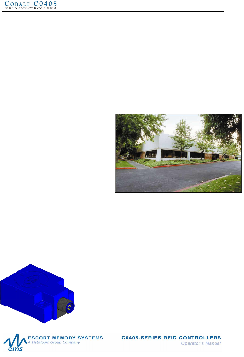
Escort Memory Systems headquarters in
Scotts Valley, CA.
CHAPTER 1:
GETTING STARTED
1.1 INTRODUCTION
Welcome to the C0405-Series RFID Controllers - Operators Manual. This manual
will assist you in the installation, configuration and operation of Escort Memory
Systems’ C0405-Series RFID Controllers.
The C0405-Series product family is a complete line of passive high frequency
read/write Radio-Frequency Identification solutions. These devices are designed to
be compact, reliable and rugged, in order to meet and exceed the requirements of
the industrial automation industry.
1.1.1 Company
Background
Escort Memory Systems is an
industry leader in providing Radio
Frequency Identification (RFID)
systems.
By consistently delivering an
extended selection of high
quality, highly durable RFID
devices, Escort Memory Systems
has built a solid reputation.
1.1.2 The C0405-Series
RFID Controller
Escort Memory Systems' C0405-Series RFID Controllers are the most compact in
our line of passive RFID controllers. Through inductive coupling, RFID enabled tags
are able to utilize the Radio Frequency (RF) field from the controller’s integrated
antenna to acquire power. By being able to receive power from the RFID controller,
the tag, itself, does not require an internal power supply or battery - and is therefore
said to be “passive”.
Passive tags, however, must enter the antenna’s electromagnetic field to establish a
link with the controller, and must remain within RF range during the entire data
transfer process. The C0405 Controller uses the internationally recognized ISM
(Industrial, Scientific and Medical) frequency of 13.56 MHz to power the
tag, while modulating side-band frequencies for communicating data.
The entire RFID system works by attaching a tag to a product or its
carrier. The RFID tag acts as an electronic identifier, portable job
sheet, or real-time tracking database. Tags are identified, read
and written to by issuing specific commands from a host computer.
RFID tags can be read and written to through any nonconductive,
non-metallic material, while moving or standing still, in or out of the
direct line of sight.
CHAPTER 1: GETTING STARTED
P/N: 17-1328 REV 02 (08/07) PAGE 11 OF 83
The C0405-Series controllers provide cost effective RFID data collection and control
solutions to shop floor, item-level tracking and material handling applications. They
are compatible with all LRP and HMS and T-Series RFID tags from Escort Memory
Systems.
1.1.3 C0405 RFID Controller Features
§ High performance, low-cost, 13.56MHz RFID controller with integrated RF
antenna
§ Supports multiple RF, ABx, air and serial communications protocols
§ Small controller size: approximately 40mm x 50mm - internal antenna
dimensions: 36mm x 36mm
§ Flash memory for software updates and configuration storage
§ Auto configurable / software programmable
§ Eight LED indicators display power, COM port activity, RF activity, Subnet16
Node ID, system diagnostics, error codes and controller status
§ Reads/Writes ISO 14443A and ISO 15693 compatible RFID tags - range up
to 50mm with ISO 144433 tags and 90mm with ISO 15693 tags
§ Reads/Writes LRP, HMS, and T-Series tags from EMS
§ FCC/CE/TELEC agency compliance certification (PENDING)
§ IP67 rated M12 interface connector (8-pin for RS232, 5-pin for RS485/USB)
§ Fully encapsulated electronics
1.1.4 About this Manual
This manual provides guidelines and instructions on how to install and operate
C0405-Series RFID Controllers. Also included are descriptions of the RFID command
set with instructions describing how to issue commands to the C0405-Series RFID
Controllers.
NOTE:
Occasionally in this manual, the C0405-Series RFID Controller is referred to as the
C0405 Controller, the C0405 or just simply the controller.
Who Should Read this Manual?
This manual should be read by those who will be installing, configuring and operating
C0405-Series RFID Controllers. This may include the following people:
§ System Integrators
§ Project Managers
§ IT Personnel
§ System and Database Administrators
§ Software Application Engineers
§ Service and Maintenance Engineers
CHAPTER 1: GETTING STARTED
P/N: 17-1328 REV 02 (08/07) PAGE 12 OF 83
1.1.5 HEX Notation
Throughout this manual, numbers expressed in Hexadecimal notation are prefaced
with “0x”. For example, the number "10" in decimal is expressed as "0x0A" in
hexadecimal. See Appendix D for a chart containing Hex values, ASCII characters
and their corresponding decimal integers.
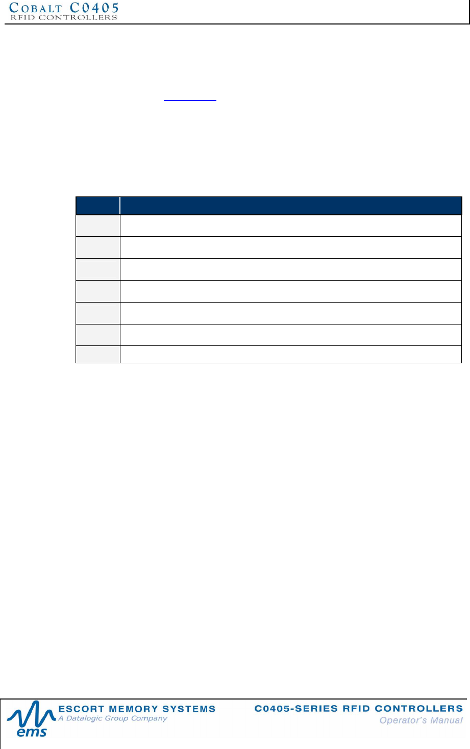
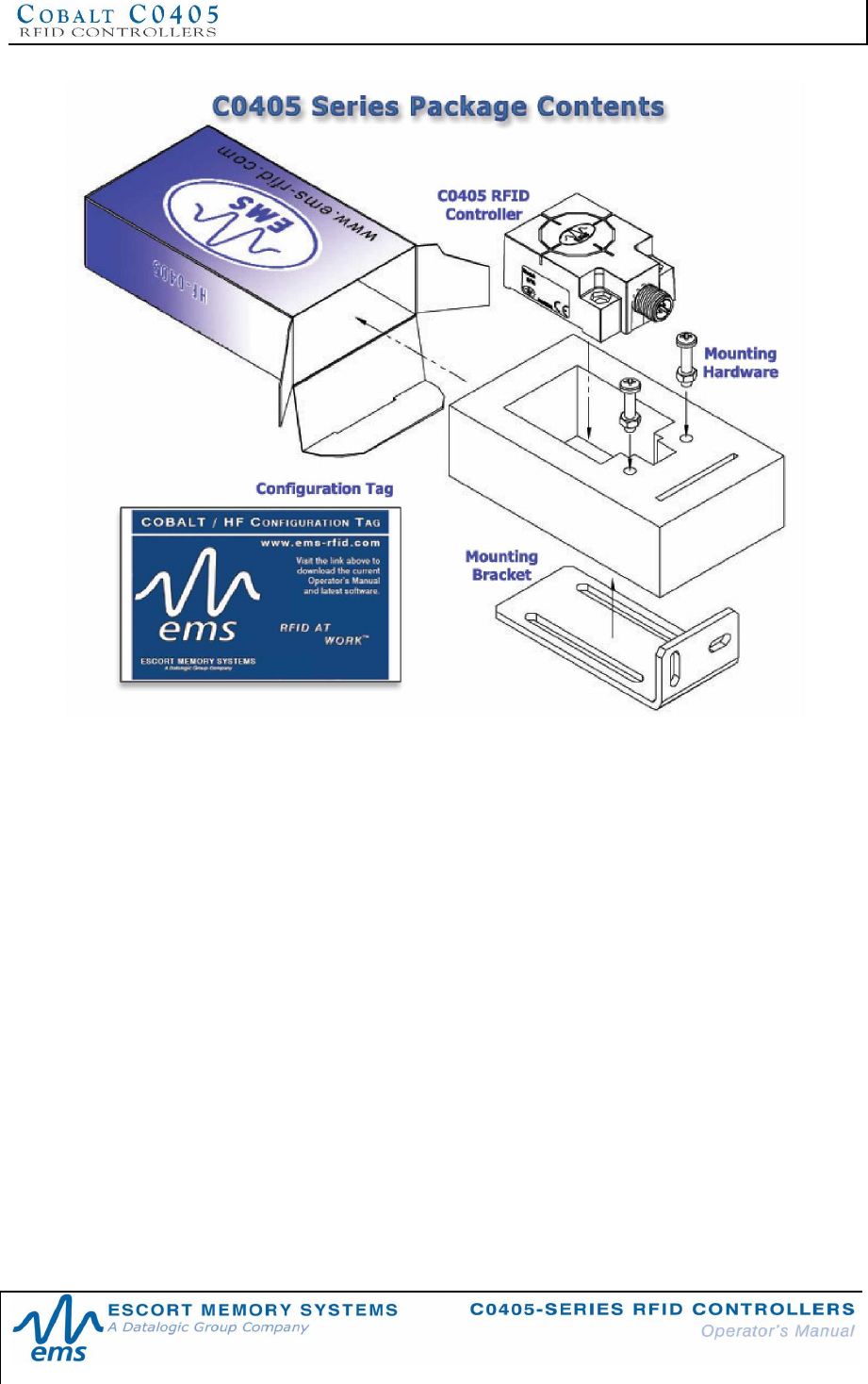
1.1.6 Contents of the C0405 Product Package
Unpack the C0405 hardware and accessories. Inspect each item for evidence of
damage. If an item appears to be damaged, notify your distributor or EMS.
The C0405 product package contains the following components:
QTY DESCRIPTION
1C0405-XXX-01 RFID Controller
1C0405-XXX-01 RFID Controller – Installation Guide
1Cobalt HF Configuration Tag (I-CODE SLi)
1Mounting Bracket
2Screws (M4, 20mm, PPH 18-8\302 SS)
2Washers (M4 locking)
2Nuts (M4, 18-8\302 SS)
Table 1-1: C0405 Product Package Contents List
Note: XXX = 232, 485 or USB
CHAPTER 1: GETTING STARTED
P/N: 17-1328 REV 02 (08/07) PAGE 13 OF 83
Figure 1-1: C0405 Package Contents Diagram
1.1.7 User Supplied Components
To configure a complete RFID system, you will need to provide the following items:
•HMS, LRP, or T-Series RFID tags
•Controller-to-Host communication interface cable: (RS232, RS485 or USB)
•Host device: (PC, PLC, MUX32, TCP/IP, Ethernet/IP, Subnet16 Gateway
or Hub)
•LPS (Limited Power Source) power supply: 10~30VDC, 2.4W (100mA @
24VDC) - per controller
•Mating connectors: (when applicable)
CHAPTER 1: GETTING STARTED
P/N: 17-1328 REV 02 (08/07) PAGE 14 OF 83
1.2 COMMUNICATION OPTIONS
There are three distinct versions of the C0405-Series RFID Controller. Each model
provides support for one specific communication interface requirement.
Through the Subnet16 protocol, multiple C0405-485-01 controllers can be networked
via a single bus that is connected to an EMS Subnet16 Gateway or Hub interface
module.
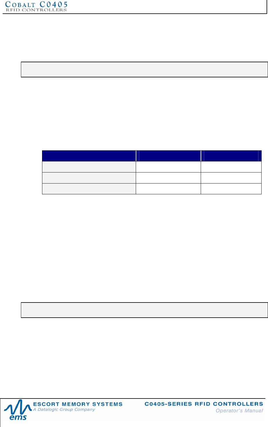
1.2.1 Connection and Communication Interface Options
CONTROLLER
MODEL CONNECTION
TYPE COMMUNICATION
INTERFACE MAX CABLE
LENGTH
C0405-232-01 RS232 Point-to-Point, Host/Controller 15 Meters
C0405-485-01 RS485 Subnet16 Multidrop bus
architecture via Subnet16™
Gateway or Hub
300 Meters
C0405-USB-01 USB 2.0 Point-to-Point, Host/Controller 5 Meters
Table 1-2: Connection and Communication Interface Options
1.2.2 C0405 Controllers - Interface Connectors
CONTROLLER MODEL INTERFACE CONNECTOR
C0405-232-01 8-pin, male M12 connector
C0405-485-01 5-pin, male M12 connector
C0405-USB-01 5-pin, male, reverse keyed M12 connector
Table 1-3: C0405 Controllers - Interface Connectors
See Appendix B: Models & Accessories for more information on model numbers,
parts and accessories for all C0405-Series RFID Controllers.

CHAPTER 2: INSTALLING THE C0405
P/N: 17-1328 REV 02 (08/07) PAGE 15 OF 83
CHAPTER 2:
INSTALLING THE C0405
2.1 PREPARING FOR INSTALLATION
C0405-Series RFID Controllers support direct connections for point-to-point
(host/controller) applications (RS232, RS485 and USB). Up to 16 C0405-485 units
can be networked via Subnet16 Gateway interface module and Escort Memory
Systems’ Subnet16™ Multidrop Bus Architecture. Host/controller data transmission is
achieved via 5-pin or 8-pin serial interface cable.
2.1.1 Installation Guidelines
•Conduct a test phase where you will construct a small scale, independent
network that includes only the essential devices required to test your RFID
application. To avoid possible interference with other devices, do not initially
connect your RFID testing environment to an existing local area network.
•RF performance and read/write range can be negatively impacted by the
proximity of metallic objects. Avoid mounting the controller within 44mm (1.75
inches) of any metallic object or surface.
•If electrical interference is encountered (as indicated by a reduction in
read/write performance), relocate the controller to an area free from potential
sources of interference.
•Route cables away from other unshielded cables and away from wiring
carrying high voltage or high current. Avoid routing cables near motors and
solenoids.
•Refrain from mounting the controller near sources of EMI (electro-magnetic
interference) or near devices that generate high ESD (electro-static
discharge) levels.
•Always use adequate ESD prevention measures to dissipate potentially high
voltages. Cobalt controllers are designed to withstand 8kV of direct electro-
static discharge (ESD) and 15kV of air gap discharge. However, it is not
uncommon for some RFID applications to generate considerably higher ESD
levels.
•For applications using multiple RFID controllers operating at the 13.56 MHz
frequency, maintain a minimum distance of at least 20 centimeters between
adjacent RF devices.

CHAPTER 2: INSTALLING THE C0405
P/N: 17-1328 REV 02 (08/07) PAGE 16 OF 83
2.1.2 C0405 Controller Dimensions
The images below contain the dimensions of the Cobalt C0405-Series RFID
Controllers in millimeters and [inches].
Figure 2-1: C0405 RFID Controller Dimensions
CHAPTER 2: INSTALLING THE C0405
P/N: 17-1328 REV 02 (08/07) PAGE 17 OF 83
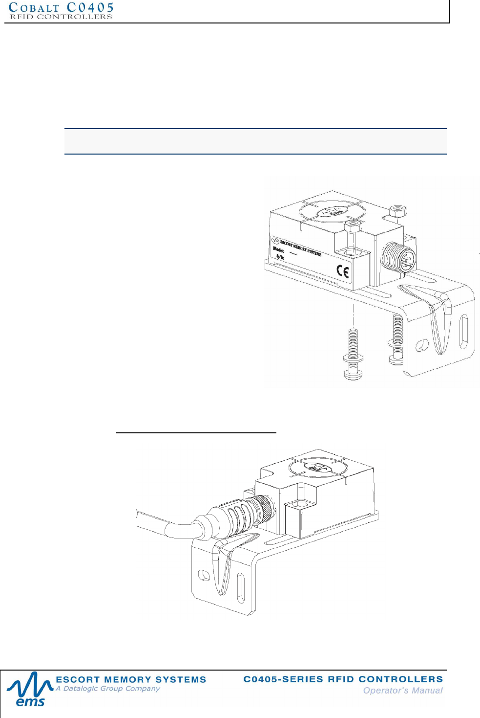
2.1.3 Mounting the Controller
C0405-Series RFID Controllers can be mounted to wood or plastic fixtures. The units’
ship with an L-shaped, polycarbonate, mounting bracket and the necessary hardware
required to fasten the controller to the bracket. The bracket is designed to help isolate
the RFID controller from metal surfaces and the affect of spurious noise electronically
conducted through metal.
NOTE: The controller may be mounted horizontally or vertically, but should be aligned
in such a manner that the LED indicators can be seen during operation.
1. Select a suitable location to mount
the C0405 Controller.
2. Attach the C0405 Controller to the
mounting bracket using the two sets
of M4 screws, washers and nuts
provided. Place the nuts in each of
the two hex-shaped recessed
cavities at the rear of the C0405.
3. After aligning the mounting bracket
with the two mounting holes on the
controller, insert both M4 screws
(with washers) into the controller
from the underside and tighten
completely using a standard Phillips
#2 head screwdriver.
4. Fasten the other end of the mounting
bracket to your work area.
Torque Specification
Tighten the two M4 screws used to fasten the controller to the bracket (and any user
provided screws used to mount the bracket to the work area) to the following torque
setting: 0.7 Nm or equivalent to 6 lbs / inch
Figure 2-2: C0405 Controller Attached to Bracket with Cable Connected
CHAPTER 2: INSTALLING THE C0405
P/N: 17-1328 REV 02 (08/07) PAGE 18 OF 83
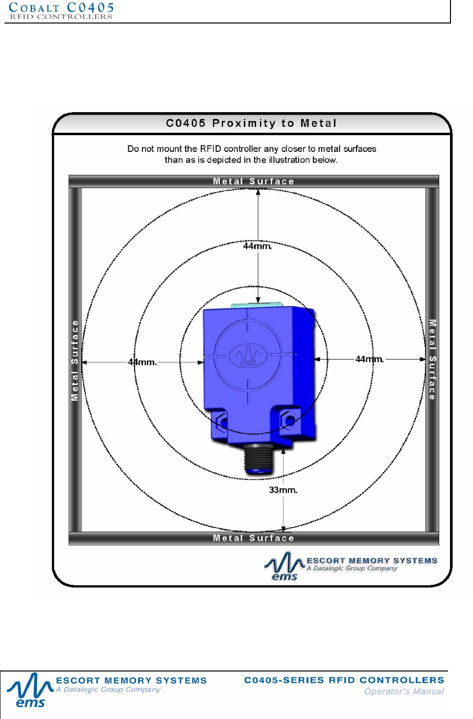
2.1.4 Proximity to Metal
RFID devices can be negatively impacted by the presence of metallic objects. Avoid
mounting the controller within 44mm (approximately 2 inches) of metal surfaces or
near sources of electro magnetic interference (EMI) and electrical noise.
Figure 2-3: C0405 Proximity to Metal
CHAPTER 2: INSTALLING THE C0405
P/N: 17-1328 REV 02 (08/07) PAGE 19 OF 83
2.2 INSTALLING THE C0405-232-01 CONTROLLER
The C0405-232-01 RFID Controller is designed for point-to-point RFID applications,
where the distance from host to controller is less than 15 meters (50 feet). The
controller connects directly to a serial communications port on a host computer via an
RS232-compatible interface cable.
NOTE: review Section 2.1.1 Installation Guidelines prior to installing the controller.
2.2.1 Steps to Install the C0405-232-01
1. Attach the controller to the mounting bracket and work area as noted in Section
2.1.3 Mounting the Controller.
2. Connect the 8-pin, female M12 connector from your serial interface cable (EMS
P/N: CBL-1478) to the 8-pin, male M12 connector on the C0405-232-01.
3. Connect the serial interface cable‘s female DE9 D-Sub connector to a COM port
on the host computer. Tighten the cable’s two locking thumbscrews.
4. Connect the 2.5mm DC power plug on the power supply transformer to the DC
power jack receptacle on the serial interface cable. Tighten the locking ring to
prevent power from becoming disconnected during use.
5. Plug the power supply transformer into a suitable AC power source. Apply power
to the controller after all cable connections have been made. The LEDs on the
unit will flash. For the C0405-232 model, the amber Node 20 LED will remain light
to indicate that the controller is in RS232 mode.
6. On the host computer, set COM port parameters to: 9600 baud, 8 data bits, 1
stop bit, no parity and no handshaking.
7. To verify operations, download the serial version of the Cobalt HF Dashboard
Utility software application from Escort Memory Systems’ website (www.ems-
rfid.com). The Dashboard Utility allows users to send RFID commands to the
controller for testing purposes.
23 2
1
PWR
24
4
22 2
0
COM
R F
RF FIELD
LED 20will
illuminate to
indicate
RS232
mode.
CHAPTER 2: INSTALLING THE C0405
P/N: 17-1328 REV 02 (08/07) PAGE 20 OF 83
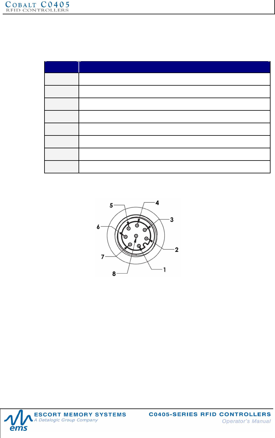
2.2.2 C0405-232-01 Cabling Information
The C0405-232-01 has one 8-pin, male M12 interface connector.
C0405-232-01 Interface Connector - Pinout
PIN # DESCRIPTION
110~30VDC POWER
20VDC (POWER GROUND)
3NOT CONNECTED
4NOT CONNECTED
5NOT CONNECTED
6RX
7TX
8SGND (SIGNAL GROUND)
Table 2-1: C0405-232-01 Interface Connector Pinout
C0405-232-01 Interface Connector - Diagram
Cabling Part Numbers for the C0405-232-01
•CBL-1478: Cable Assembly (8-pin, female M12 to RS232; with 2.5mm DC power
jack, 2m)
•CBL-1488-XX: Cable (8-pin, female M12 to bare wire leads)
•CBL-1492-XX: Cable (8-pin, right-angle female M12 to bare wire leads)
•CBL-1493: Connector (8-pos, straight female M12, field mountable)
(XX = Cable Length in Meters)
CHAPTER 2: INSTALLING THE C0405
P/N: 17-1328 REV 02 (08/07) PAGE 21 OF 83
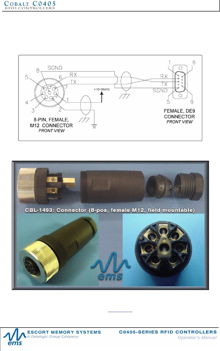
RS232 Serial Interface Cable Schematic
If you intend to assemble your own RS232 serial interface cable, follow the schematic
below. Note that signals and electrical loads applied to Pin 6 (RX) and Pin 7 (TX)
should conform to RS232 specifications. For bulk RS232 cable, see Belden cable
P/N: 9941 (www.belden.com).
Figure 2-4: RS232 Interface Cable Schematic
CBL-1493: Field Mountable Connector
Figure 2-5: CBL-1493 Connector
The CBL-1493 field mountable connector is available for connecting the C0405-232
to a host PC via bulk cable. (See Appendix B for more information regarding cables
and connectors for the entire line of C0405-Series RFID Controllers).
CHAPTER 2: INSTALLING THE C0405
P/N: 17-1328 REV 02 (08/07) PAGE 22 OF 83
2.3 INSTALLING THE C0405-485-01 CONTROLLER
The C0405-485-01 RFID Controller supports RS485 communications and Escort
Memory Systems’ Subnet16™ Multidrop bus architecture and RFID network protocol.
Through the Subnet16 protocol, multiple C0405-485-01 units can be connected to
one Subnet16™ RFID Gateway or Hub interface device. The Gateway or Hub
assigns each attached C0405-485-01 a unique Node ID number through which
communication with a host PC and/or Programmable Logic Controller (PLC) is
achieved.
NOTE: review Section 2.1.1 Installation Guidelines prior to installing the controller.
2.3.1 Steps to Install the C0405-485-01
1. Attach the controller to the mounting bracket and work area as noted in Section
2.1.3 Mounting the Controller.
2. Connect the 5-pin, female end of your Subnet16-compatible cable to the 5-pin,
male M12 interface connector on the C0405-485. Connect the opposite end of
this cable to an EMS Subnet16 Gateway or Hub device. Connect the Gateway or
Hub to a host computer via Category 5E Ethernet cabling*.
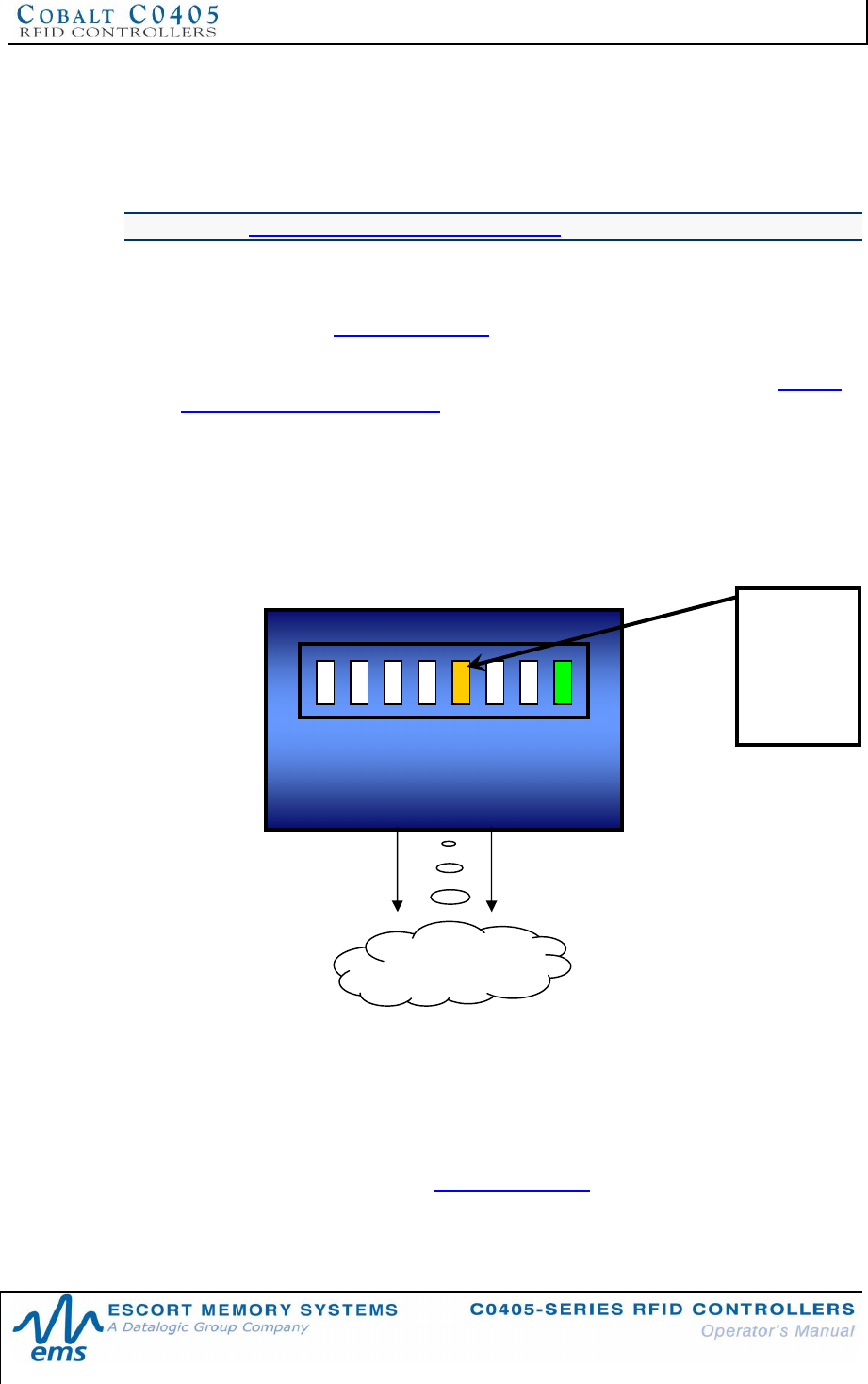
3. Turn the power supply ON. The green power LED will illuminate when power is
applied to the unit. The five amber Node LEDs, when lit, display the Node ID
value (in binary format from right to left) currently assigned to the C0405-485
RFID Controller. Note: the default Node ID is Node 00; in which case none of the
amber Node ID LEDs will be lit.
4. To verify operations, download the TCP/IP version of the Cobalt HF Dashboard
Utility software application from Escort Memory Systems’ website (www.ems-
rfid.com). The Cobalt HF Dashboard Utility allows Gateway/Hub users to send
RFID commands to any connected controller for testing purposes.
*For more information regarding the installation of a Subnet16 Gateway or Subnet16
Hub, refer to the Operator’s Manual for each product, available online at www.ems-
rfid.com.
RF FIELD
24 2
2
PWR
23 2
1 2
0
COM
R F
Yellow
Node
LEDs 20 24
indicate Node
ID for C0405-
485 model
CHAPTER 2: INSTALLING THE C0405
P/N: 17-1328 REV 02 (08/07) PAGE 23 OF 83
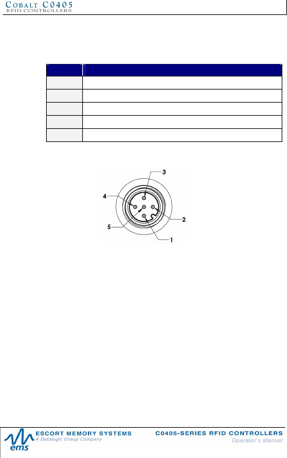
2.3.2 C0405-485-01 Cabling Information
The C0405-485-01 has one 5-pin, male M12 interface connector.
C0405-485-01 Interface Connector - Pinout
PIN # DESCRIPTION
1SGND (SIGNAL GROUND)
210~30VDC POWER
30V (POWER GROUND)
4TX/RX+
5TX/RX-
Table 2-2: C0405-485-01 Interface Connector - Pinout
C0405-485-01 Interface Connector - Diagram
CHAPTER 2: INSTALLING THE C0405
P/N: 17-1328 REV 02 (08/07) PAGE 24 OF 83
2.4 INSTALLING THE C0405-USB-01 CONTROLLER
The C0405-USB-01 RFID Controller is designed for point-to-point RFID applications
that support USB 2.0 communications. Host/controller data is transmitted via
standard USB cabling.
NOTE: review Section 2.1.1 Installation Guidelines prior to installing the controller.
2.4.1 Steps to Install the C0405-USB-01
1. Download the Cobalt USB driver software bundle from the Escort Memory
Systems website (www.ems-rfid.com). Extract the .zip file archive to a separate
folder on the desktop of the host computer.
2. Attach the controller to the mounting bracket and work area as noted in Section
2.1.3 Mounting the Controller.
3. Attach the, 5-pin, reverse keyed female M12 interface connector from a suitable
USB interface cable (EMS P/N: CBL-1525) to the 5-pin, reverse keyed male M12
connector on the C0405-USB.
4. Plug the remaining end of the USB interface cable into a USB port on the host
computer. The LEDs on the Cobalt should illuminate. For the C0405-USB model,
the amber LED 22 will illuminate to indicate that the controller is in USB mode.
5. Install the Cobalt USB driver. Refer to the Cobalt USB Driver Installation
Instructions (EMS Publication P/N: 17-3128) that are included in the Cobalt
USB driver archive.
6. To verify operations, download the serial version of the Cobalt HF Dashboard
Utility from the EMS website (www.ems-rfid.com). The Dashboard Utility allows
users to send RFID commands to the controller for testing purposes.
24 2
2
PWR
23 2
1 2
0
COM
R F
RF FIELD
LED 22will
illuminate
to indicate
USB
mode.
CHAPTER 2: INSTALLING THE C0405
P/N: 17-1328 REV 02 (08/07) PAGE 25 OF 83
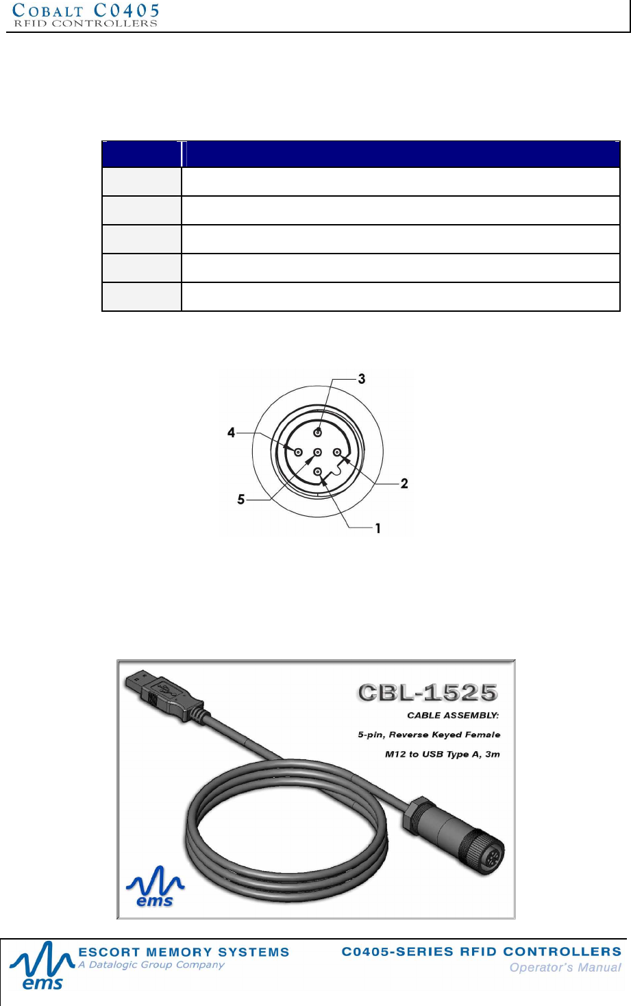
2.4.2 C0405-USB-01 Cabling Information
The C0405-USB-01 has one 5-pin, reverse keyed male M12 interface connector.
C0405-USB-01 Interface Connector - Pinout
PIN # DESCRIPTION
1+5V
2D-
3D+
4GND
5SHIELD
Table 2-3: C0405-USB-01 Interface Connector - Pinout
C0405-USB-01 Interface Connector - Diagram
Cabling Part Numbers for the C0405-USB-01
•CBL-1513: Cable Assembly (5-pin, reverse keyed male M12 to USB Type A, 3m)
•CBL-1514: Connector (5-pin, reverse keyed male M12 connector for USB)
•CBL-1525: Cable Assembly (5-pin, reverse keyed female M12 to USB Type A,
3m)
CHAPTER 2: INSTALLING THE C0405
P/N: 17-1328 REV 02 (08/07) PAGE 26 OF 83
2.5 ANTENNA ENVIRONMENT
The antenna used to communicate with RFID tags is integrated within the C0405
RFID Controller. Electro-magnetic interference (EMI) and the presence of metal near
the antenna’s RF field can negatively affect the communication range of the RFID
controller.
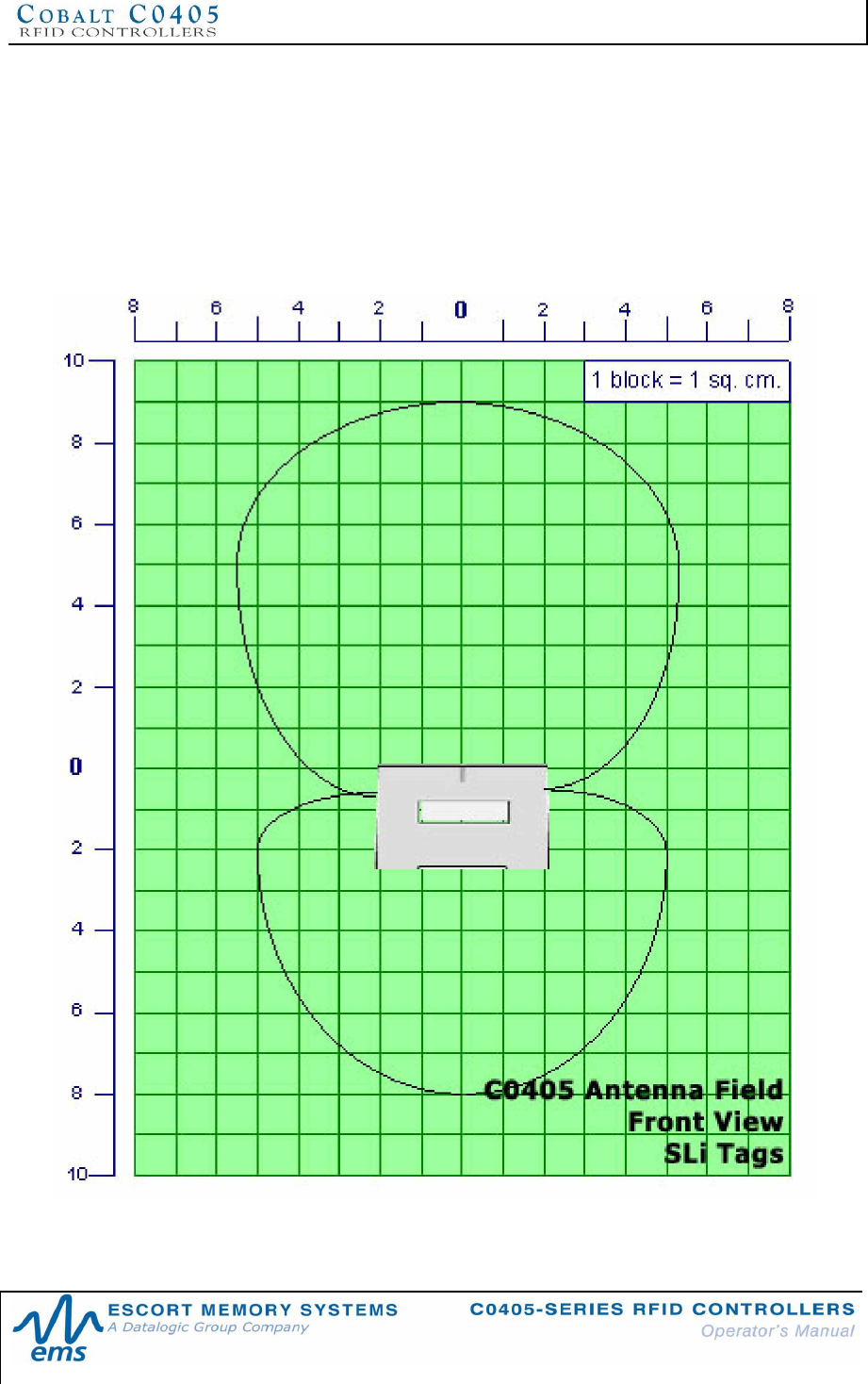
2.5.1 Typical Read Range - Front View* for SLi 54x86mm
RFID Tags
Figure 2-6: Typical Read Range - Front View* for SLi 54x86mm Tags
*Approximate Free Air H-Field Pattern
CHAPTER 2: INSTALLING THE C0405
P/N: 17-1328 REV 02 (08/07) PAGE 27 OF 83
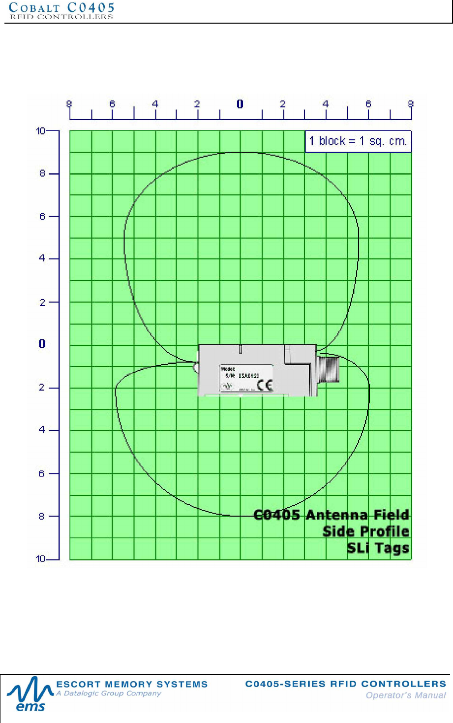
2.5.2 Typical Read Range - Side Profile* for SLi 54x86mm
RFID Tags
Figure 2-7: Typical Read Range - Side Profile* for SLi 54x86mm Tags
*Approximate Free Air H-Field Pattern
CHAPTER 2: INSTALLING THE C0405
P/N: 17-1328 REV 02 (08/07) PAGE 28 OF 83
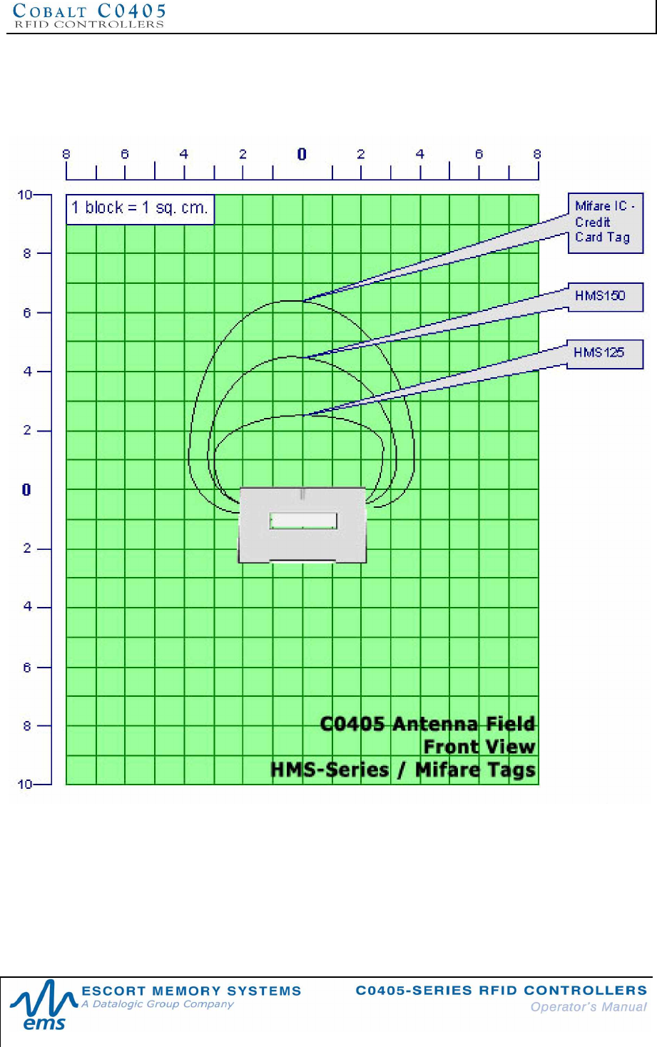
2.5.3 Typical Read Range - Front View* for HMS / Mifare
RFID Tags
Figure 2-8: Typical Read Range - Front View* for HMS / Mifare Tags
*Approximate Free Air H-Field Pattern
CHAPTER 2: INSTALLING THE C0405
P/N: 17-1328 REV 02 (08/07) PAGE 29 OF 83
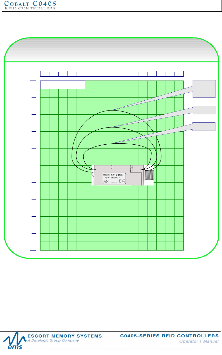
2.5.4 Typical Read Range - Side Profile* for HMS / Mifare
RFID Tags
0
2
4
6
8
10
2
4
6
8
10
0
8 246 2 4 6 8
HF-0405 Antenna Field - Side Profile
MIFARE - HMS tags
1 block = 1 sq. cm. Mifare IC -
Credit
Card Tag
HMS150
HMS125
Figure 2-9: Typical Read Range - Side Profile* for HMS / Mifare Tags
*Approximate Free Air H-Field Pattern
CHAPTER 2: INSTALLING THE C0405
P/N: 17-1328 REV 02 (08/07) PAGE 30 OF 83
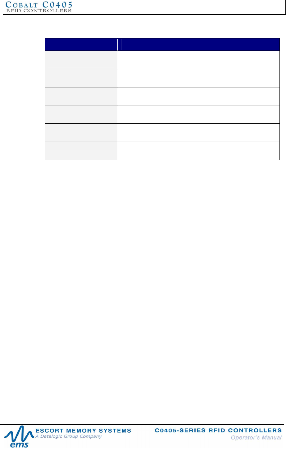
2.5.5 C0405 Antenna to EMS Tag Ranges
EMS TAG RANGE
LRP125S Up to 38mm
LRP250 Up to 60mm
LRP525 (HTS) Up to 70mm
LRP-C5486S Up to 74mm
HMS125 Up to 25 mm
HMS150 Up to 45mm
Table 2-4: C0405 Antenna to EMS Tag Ranges
CHAPTER 3: POWER & COMMUNICATION
P/N: 17-1328 REV 02 (08/07) PAGE 31 OF 83
CHAPTER 3:
POWER & COMMUNICATION
3.1 POWER REQUIREMENTS
3.1.1 C0405-232-01/C0405-485-01 Power Requirements
C0405-232-01 and C0405-485-01 RFID controllers requires an agency compliant
LPS power supply capable of providing 10~30VDC, 2.4W (100mA @ 24VDC).
EMS Power Supplies for C0405-232 and C0405-485 RFID Controllers
PART NUMBER DESCRIPTION
00-1166 45W, 1.88A max @ 24VDC
00-1167 100W, 4.17A max @ 24VDC
00-1168 120W, 5.0A max @ 24VDC
Table 3-1: EMS Power Supplies
3.1.2 C0405-USB-01 Power Requirements
The C0405-USB-01 RFID Controller obtains power directly from the USB bus.
Typical power consumption under normal conditions = 1W (200mA @ 5VDC).
CAUTION:
Do not connect or disconnect the C0405 while power is being applied. Turn the power
supply off at the source prior to connecting or disconnecting the unit. Reapply power
only after the controller has been reconnected.
Use only high quality, shielded cables for power and interface connections. See
Appendix B for a list of compatible cables and network components.
CHAPTER 3: POWER & COMMUNICATION
P/N: 17-1328 REV 02 (08/07) PAGE 32 OF 83
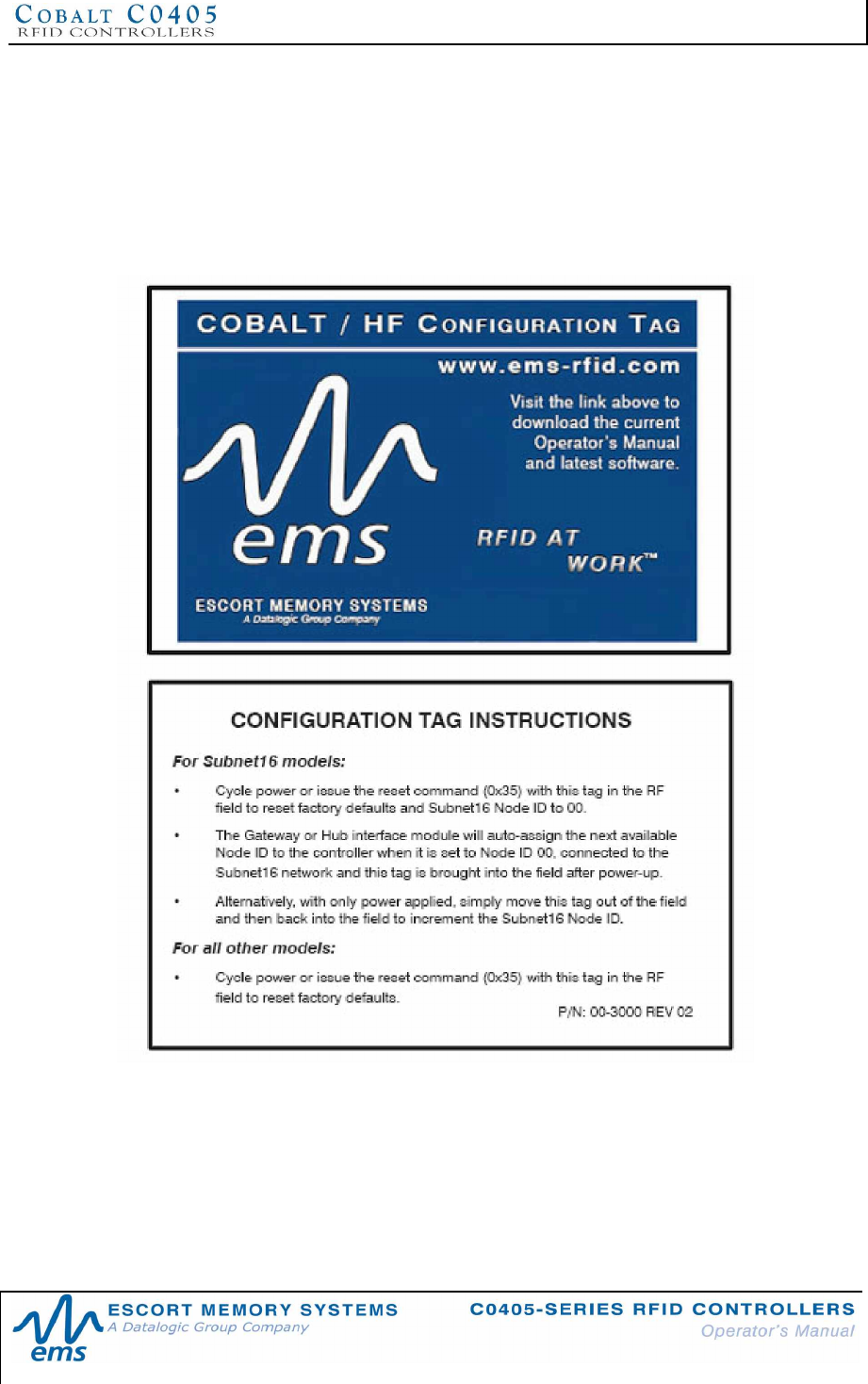
3.2 HF-SERIES CONFIGURATION TAG
3.2.1 Configuration Tag Overview
In the past, RFID controllers had multiple jumpers and DIP-switches that were used
to set configuration parameters. C0405-Series RFID Controllers do not require
jumpers or DIP-switches because they are software configurable via commands sent
from a host PC as well as through the use of a Cobalt HF Configuration Tag.
Figure 3-1: Cobalt HF Configuration Tag
In the event that serial communication parameters become improperly assigned,
recycle power to the RFID controller while holding the Configuration Tag in the
controller’s RF field. When power returns to the controller, factory default settings will
be read from the Configuration Tag and the controller’s internal configuration will be
reset. For the C0405-485, this Configuration Tag can also be used manually to set
the device’s Node ID. It is recommended to write the product serial number on the
tag and store it in a safe place.
CHAPTER 3: POWER & COMMUNICATION
P/N: 17-1328 REV 02 (08/07) PAGE 33 OF 83
3.2.2 Configuration Tag Memory Map
Containing a Philips I-CODE SLi IC, the Configuration Tag is a 112-byte ISO 15693
compliant tag that has had much of its memory locked at the factory to prevent
important data from being erased or overwritten. Of the 112 bytes of memory, the first
80 bytes (addresses 0x0000 – 0x0079) are allocated to storing factory default
settings, product ID and manufacturing information. The first 16-bytes (addresses
0x0000 through 0x0015) contain specific data that the controller reads to identify this
special tag.
You are welcome to experiment with the remaining 32 bytes available on this tag
(addresses 0x0080 – 0x0111). All addresses on the Configuration Tag can be read
and no user identifiable information is stored.
3.2.3 Using the Configuration Tag
Resetting the Controller to Default Settings
The Configuration Tag can be used to reset factory defaults to all versions of the
C0405. To restore factory defaults, cycle power to the controller or issue the reset
command (Command 0x35) while the Configuration Tag is in the RF field. Two
seconds after power returns to the C0405, remove the Configuration Tag from the RF
field. The controller will be reset to the following default settings:
CONFIGURATION PARAMETER DEFAULT SETTING
Command Protocol ABx Fast – No Checksum
Tag Type: ISO 15693 (I-Code SLi)
Serial Communications 9600, N, 8, 1, N (C0405-232 model)
Node ID 00 (C0405-485 model)
Table 3-2: Configuration Tag - Controller Defaults
Setting Node ID Manually (C0405-485 only)
To set the Node ID on C0405-485 models, cycle power to the controller or issue the
reset command (Command 0x35) while the Configuration Tag is in the RF field. Two
seconds after power returns to the C0405, remove the Configuration Tag from the RF
field. This will set the Node ID value back to the default value of Node ID 00. (Note:
see Section 4.1 - LED Functions Overview for LED positions and colors).
• All amber Node LEDs should be off.
After power returns to the unit, move the Configuration Tag out of the RF field and
then back into the RF field to increment the Node ID from zero to one.
• Amber Node LED 20 should now be lit.
Removing the Configuration Tag from the controller’s RF field and then bringing it
back into the field will increment the Node ID value once each time the Configuration
Tag re-enters the RF field.
• The amber Node LEDs will display, in binary, the Node ID vale assigned to
the controller (See Chapter 4 for more information on LED status).

CHAPTER 3: POWER & COMMUNICATION
P/N: 17-1328 REV 02 (08/07) PAGE 34 OF 83
This procedure can be used to cycle through all 16 possible Subnet Nodes. Note that
after reaching Subnet Node 16, incrementing the Node ID value once more returns
the controller to Node ID 0.
After selecting the desired Node ID value, reset the C0405 with the Configuration Tag
out of RF range to allow the unit to reset completely and resume operation under its
new Node ID.
Setting Node ID Automatically (C0405-485 only)
To allow a Subnet16 Gateway or Hub to assign the Subnet Node ID to a C0405-485
automatically, reset the controller to Node ID 00, connect the controller to the network,
and apply power to the Subnet16 bus. When the Gateway or Hub comes on line,
hold the Configuration Tag in the RF field of the controller for several seconds to
allow the Gateway or Hub to assign the next available Node ID value. For more
information on using a Subnet16 Gateway and Hub product to auto-assign Subnet
Node ID values, please refer to the Operator’s Manuals for theSubnet16 Gateway
and/or subnet16 Hub.
CHAPTER 4: LED STATUS
P/N: 17-1328 REV 02 (08/07) PAGE 35 OF 83
CHAPTER 4:
LED STATUS
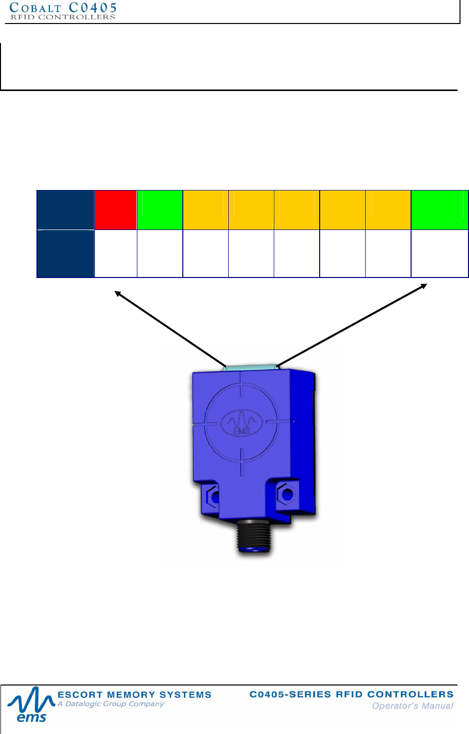
4.1 LED FUNCTIONS OVERVIEW
C0405-Series RFID Controllers have eight LED status indicators. The LEDs are
conveniently located on the top panel of the device and display everything from
antenna RF and communications activity to Node ID, diagnostic information and
power status.
LED
Color Red Green Amber Amber Amber Amber Amber Green
Function RF
Activity
COM
Activity
Node
24(16)
Node
23(8)
Node
22(4)
Node
21 (2)
Node
20 (1)
Power
On
CHAPTER 4: LED STATUS
P/N: 17-1328 REV 02 (08/07) PAGE 36 OF 83
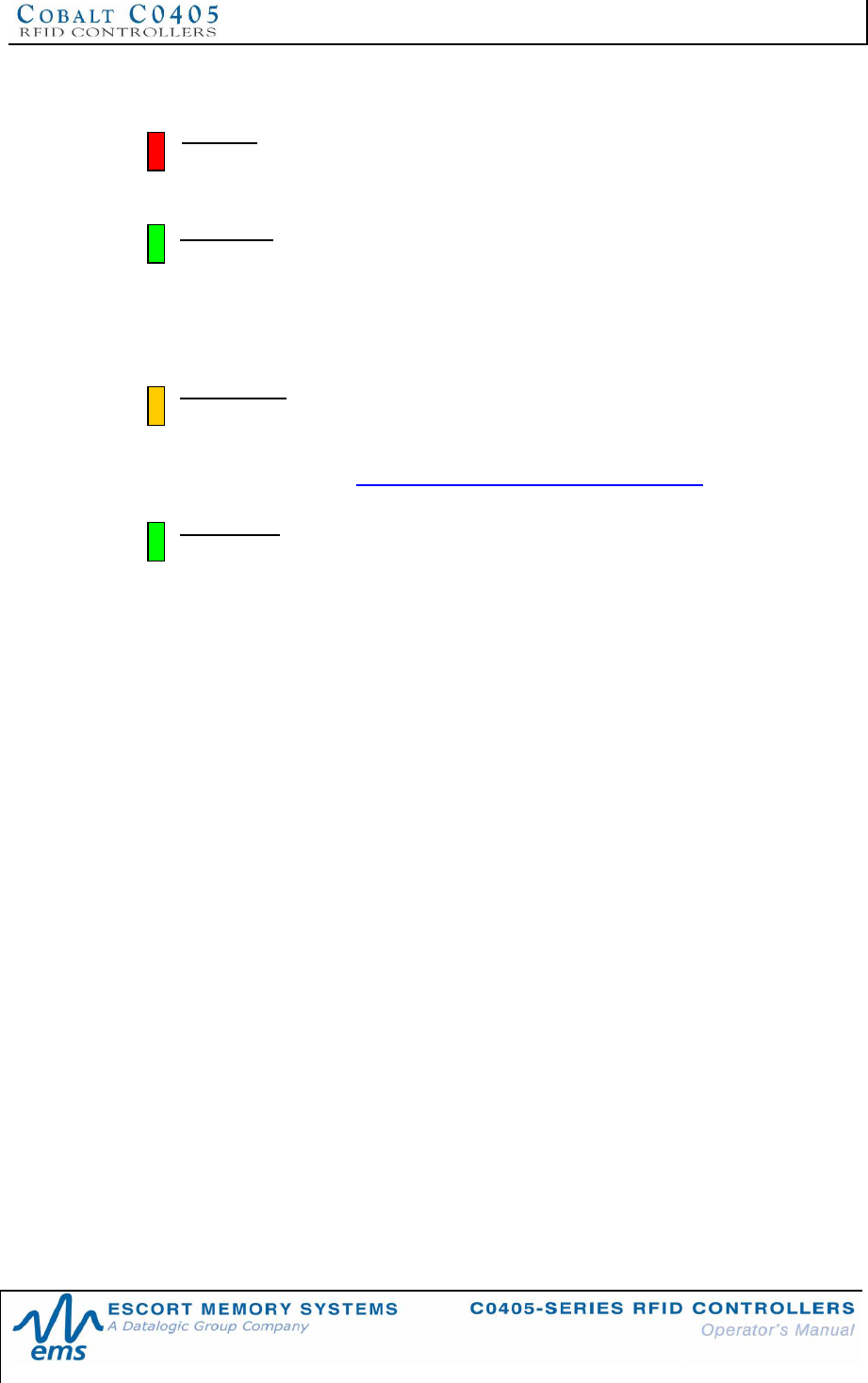
4.1.1 LED Descriptions
RF LED: Color is red. The RF LED will illuminate while RF power is being
transmitted by the antenna, and will stay ON during the entire RF operation. By
default, this occurs each time an RF command is being executed.
COM LED: Color is green. The COM LED indicates that data is being transmitted
between the host and the C0405. On receipt of a command, the COM LED will
begin flashing ON and OFF rapidly. After the controller generates the command
response, COM LED flashing will halt. When in Continuous Read mode, the COM
LED will remain ON and will turn OFF briefly only while data is being read or written
to a tag.
Node LEDs: Colors are amber. These five LEDs indicate the serial
communications type for C0405-232 and -USB models. For the C0405-485
model, the five amber LEDs indicate (in binary from right to left) the current Node
ID value assigned to the controller. The five amber LEDs also flash an error code
when a fault occurs (see Section 4.3 LED Displayed Error Codes).
Power LED: Color is green. The Power LED will remain ON while power is
applied to the C0405-Series Controller.
CHAPTER 4: LED STATUS
P/N: 17-1328 REV 02 (08/07) PAGE 37 OF 83
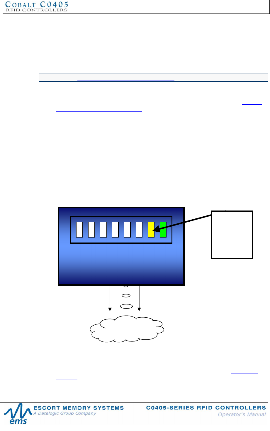
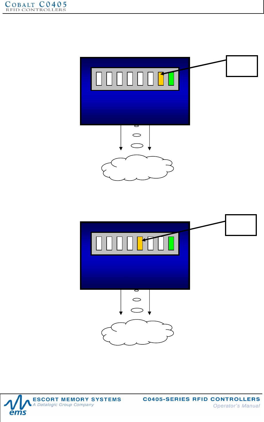
4.1.2 C0405-232 LED Status
On the C0405-232 model, the amber Node 20 LED will stay on indefinitely to indicate
that the controller is in RS232 mode.
4.1.3 C0405-USB LED Status
On the C0405-USB model, the amber Node 22 LED will stay on indefinitely to indicate
that the controller is in USB mode.
23 2
1
PWR
24 2
2 2
0
COM
R
F
RF FIELD
LED 20
23 2
1
PWR
24 2
2 2
0
COM
R F
RF FIELD
LED 22
CHAPTER 4: LED STATUS
P/N: 17-1328 REV 02 (08/07) PAGE 38 OF 83
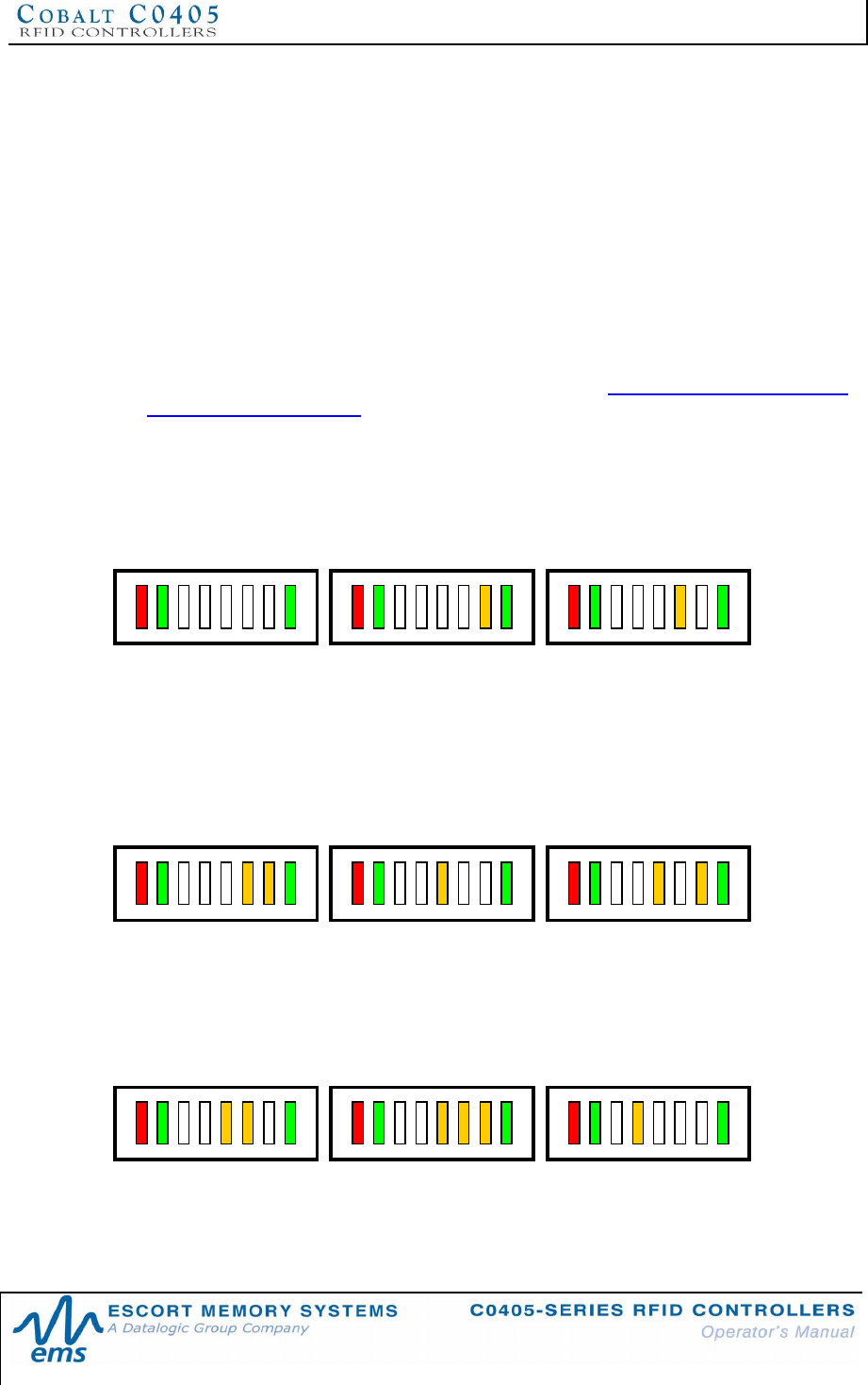
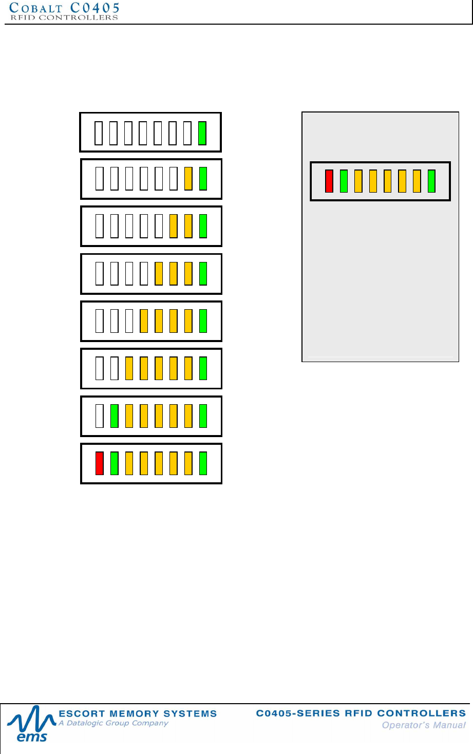
Node 0
(default) Node 1 Node 2
Node 3 Node 4 Node 5
Node 6 Node 7 Node 8
4.1.4 C0405-485 LED Status
When used in conjunction with a Subnet16 Gateway or Subnet16 Hub, the five
amber LEDs on the C0405-485 model indicate (in binary, weighted by powers of two,
from right to left) the Node ID value currently assigned (for which there are 16).
For example, 20 (0x01) = Node ID 1, 21 (0x02) = Node ID 2, 22 (0x04) = Node ID 4, 23
(0x08) = Node ID 8, 24(0x10) = Node ID 16.
By default, C0405-485 RFID Controllers ship with their Node ID value set to zero
(none of the five amber Node LEDs will be lit). After the controller is connected to a
Subnet16 bus and has been recognized by a Subnet16 Gateway or Hub, it will be
automatically assigned the next available Node ID (1 through 16). For configuring or
resetting the Node ID using the Configuration Tag, see Chapter 3 Section 3.2: HF-
Series Configuration Tag.
Node ID Values for the C0405-485
P
W
R
242321
2220
C
O
M
R
F
P
W
R
242321
2220
C
O
M
R
F
P
W
R
242321
2220
C
O
M
R
F
P
W
R
242321
2220
C
O
M
R
F
P
W
R
242321
2220
C
O
M
R
F
P
W
R
242321
2220
C
O
M
R
F
P
W
R
242321
2220
C
O
M
R
F
P
W
R
242321
2220
C
O
M
R
F
P
W
R
242321
2220
C
O
M
R
F
CHAPTER 4: LED STATUS
P/N: 17-1328 REV 02 (08/07) PAGE 39 OF 83
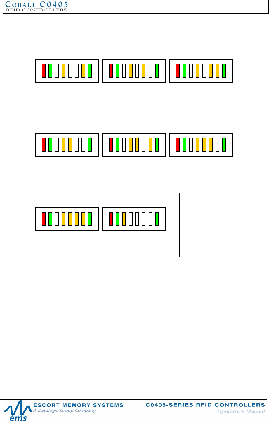
Node 9 Node 10 Node 11
Node 12 Node 13 Node 14
Node 15 Node 16
P
W
R
242321
2220
C
O
M
R
F
P
W
R
242321
2220
C
O
M
R
F
P
W
R
242321
2220
C
O
M
R
F
P
W
R
242321
2220
C
O
M
R
F
P
W
R
242321
2220
C
O
M
R
F
P
W
R
242321
2220
C
O
M
R
F
P
W
R
242321
2220
C
O
M
R
F
P
W
R
242321
2220
C
O
M
R
F
Node ID 00 is the default Node
ID for C0405-485 controllers.
In this state, the controller will
be unable to perform
commands until it has been
initialized by a Gateway or
Hub, at which time it will be
assigned a Node ID between 1
and 16.
CHAPTER 4: LED STATUS
P/N: 17-1328 REV 02 (08/07) PAGE 40 OF 83
4.2 SPECIAL LED OPERATION FUNCTIONS
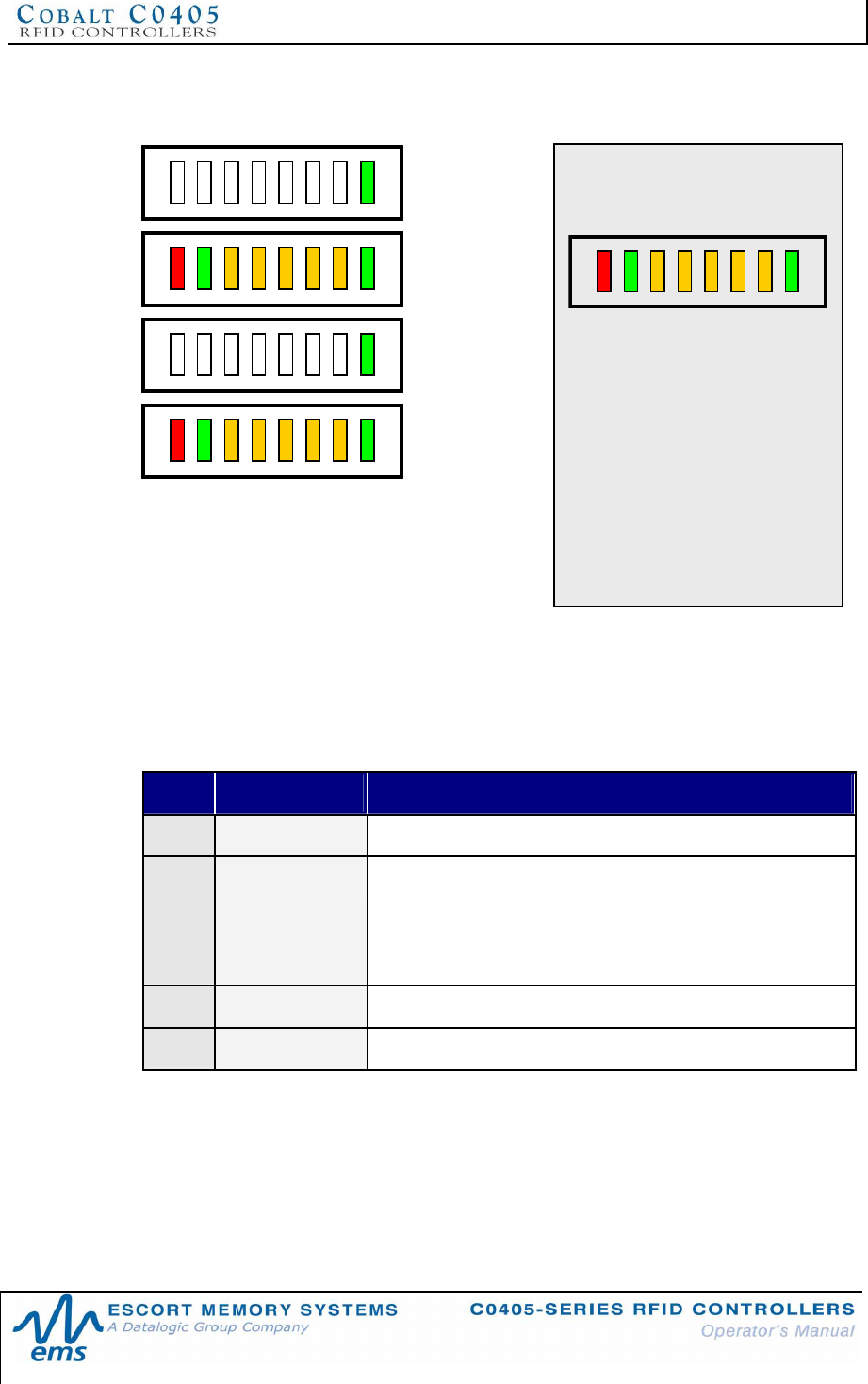
4.2.1 Updating the Controllers Firmware
Updating Firmware
(Part 1)
With the PWR LED on the
right, the remaining LEDs will
illuminate one at a time
sequentially from right to left to
indicate that new firmware
code is being copied to
internal memory.
The LEDs will repeat this R to
L sequence until the C0405
has completely received the
firmware installation file.
CHAPTER 4: LED STATUS
P/N: 17-1328 REV 02 (08/07) PAGE 41 OF 83
4.2.2 Continuous Read Mode LED Behavior
The table below describes the behavior of the LEDs when the unit is in Continuous
Read Mode (Command 0x0D).
LED BEHAVIOR DESCRIPTION
PWR ON Controller is powered and functioning
COM ON Duplicate Read Delay 1 and a tag has entered the RF field.
COM LED will remain ON while a tag is in the RF field.
After the tag has exited the RF field the COM light will remain
ON for the duration of the Duplicate Read Delay before turning
OFF
COM BLINKING Duplicate Read Delay = 0 and a tag is in the RF field
RF ON Continuous Read mode is enabled
Table 4-1: Continuous Read Mode - LED Behavior
Updating Firmware
(Part 2)
After the new firmware has
been copied to internal
memory, the LEDs will blink
ON and OFF repeatedly during
which time the new code is
being written to flash memory.
Warning: do not cancel or
abort this operation, AND do
not unplug or remove power
from the controller under any
circumstance until this
procedure is completed.
CHAPTER 4: LED STATUS
P/N: 17-1328 REV 02 (08/07) PAGE 42 OF 83
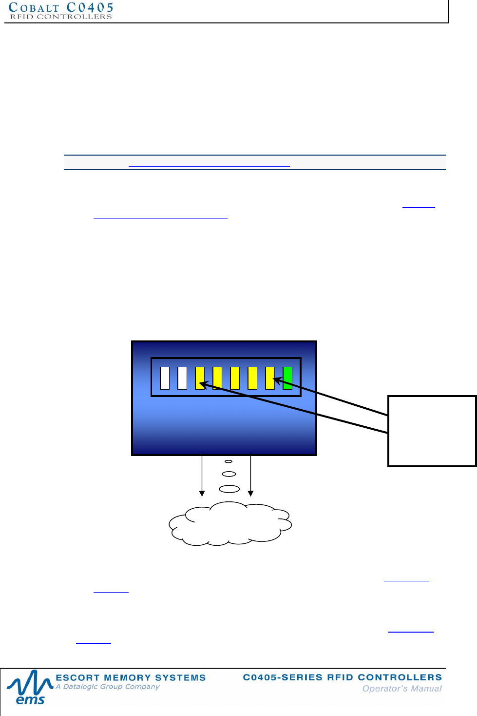
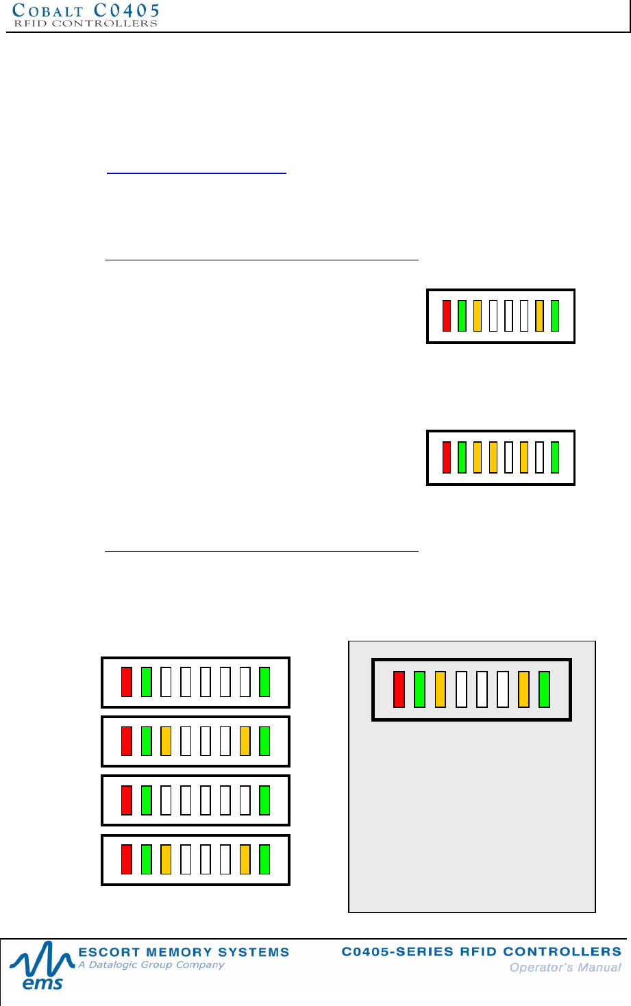
4.3 LED DISPLAYED ERROR CODES
When an error occurs, other than a Timeout, the red RF LED and one or more amber
Node LEDs will flash in unison. The amber Node LEDs flash a binary representation
of the one-byte error code value of the fault that transpired. The COM LED will also
be illuminated after an error occurs to help orient the binary LED positions. See
Chapter 8: ABx Error Codes for a complete list of errors and their descriptions.
To display the single-byte error code in binary, the two left-most amber Node LEDs
(LED 24and LED 23) represent the first or most significant digit (MSD) of the error
code. The three remaining amber Node LEDs (LED 22, LED 21and LED 20) are
combined to represent the second or least significant digit (LSD) of the error code.
Examples:
•If the five amber Node LEDs (from L to R) =
ON, OFF, OFF, OFF, ON, the first digit of the
error code is a “2 “ and the second digit is a
“1,” meaning that error code 0x21 occurred
(error code 0x21 = command syntax error).
•If the five amber Node LEDs (from L to R) =
ON, ON, OFF, ON, OFF, the first digit of the
error code is a “3 “ and the second digit is a
“2,” meaning that error code 0x32 occurred
(error code 0x32 = invalid programming
address).
After an error has occurred, the red RF LED and one or more amber Node LEDs will
continue to flash the error code until a valid command is received by the controller. If
an unrecoverable error occurs, the LEDs will continuously flash the error code until
the C0405 has been reset.
P
W
R
242321
2220
C
O
M
R
F
P
W
R
242321
2220
C
O
M
R
F
P
W
R
2
4
2
3
2
1
2
2
2
0
C
O
M
R
F
This example depicts Error 0x21.
When an error occurs, the green
COM LED will remain ON to help
orient the binary LED positions. The
green power LED will also be ON
while power is applied to the C0405.

CHAPTER 5: RFID TAGS
P/N: 17-1328 REV 02 (08/07) PAGE 43 OF 83
CHAPTER 5:
RFID TAGS
5.1 RFID TAG OVERVIEW
RFID tags, which are also referred to as transponders, smart labels, or inlays, come
in a variety of sizes, memory capacities, read ranges, frequencies, temperature
survivability ranges and physical embodiments.
C0405-Series Controllers are capable of reading Escort Memory Systems’ HMS, LRP
and T-Series RFID tags as well as most tags made by other manufacturers.
5.1.1 RFID Standards
ISO 14443A
RFID integrated circuits (ICs) designed to meet ISO 14443A standards were
originally intended for use in smart cards used in secure transactions such as credit
cards, passports, bus passes, ski lift tickets, etc. For this reason there are many
security authentication measures taken within the air protocol between the RFID
controller and the tag. Escort Memory Systems was the first company to adopt ISO
14443A RFID ICs with this technology for industrial automation applications. Because
these applications do not require the level of security monetary or passport
applications require, many of these features have not been implemented in current
controllers. It is important to understand the requirements of an ISO 14443A
application before assuming a C0405-Series controller is suitable.
ISO 14443A compliant tags and controllers incorporate security authentication and
use software “keys” during each transfer of data to and from the tag. Both the RFID
controller and the tag must use the same security keys to authenticate
communication. The C0405 Controller’s operating system manages these security
features, making their existence transparent to the user. However, it is important to
understand the implications associated with ISO 14443 when using another
manufacturer’s tags. Because of these security “features,” an ISO 14443 tag made
by one manufacturer may not be readable by a C0405 Controller and an Escort
Memory Systems ISO 14443 compliant tag might not be readable by another
manufacturer’s RFID controller. C0405-Series Controllers support EMS’ security keys
for use on Mifare ISO 14443A tags.
ISO 15693
ISO 15693 was established at a time when the RFID industry identified that the lack
of standards was preventing the market from growing. Philips Semiconductor and
Texas Instruments were the major manufacturers producing RFID ICs for the
Industrial, Scientific, and Medical (ISM) frequency of 13.56MHz, but each used a
unique protocol and modulation algorithm. Texas Instruments Tag-it™ and Philips
Semiconductor’s I-CODE™ product lines were eventually standardized on the
mutually compatible ISO 15693 standard. After the decision was made to standardize,
the door opened for other silicon manufacturers to enter the RFID business, many of
which have since contributed to RFID ISO definitions. This healthy competition has
led to rapid growth in the industry and has pushed the development of other
standards, such as ISO 18000 for Electronic Product Code (EPC) applications.

CHAPTER 5: RFID TAGS
P/N: 17-1328 REV 02 (08/07) PAGE 44 OF 83
ISO 18000-3.1
The ISO 18000 standard has not been implemented in the C0405-Series Controller
at the time of publication of this manual. It is a planned product enhancement for
future release. This will provide support for EPC and Unique Identification (UID) tag
applications.
It is important to know that not all 13.56MHz RFID tags are compatible with the
C0405 and even tags that are compliant to the ISO 15693 or ISO 14443 standards
may not be compatible with RFID controllers compliant to the same standards. This is
partially because these ISO standards leave many features open to the discretion
and interpretation of the RFID equipment manufacturers to implement or define.
When using any tag other than those supplied by Escort Memory Systems, you
should ensure compatibility of those tags with your RFID system provider.
CHAPTER 5: RFID TAGS
P/N: 17-1328 REV 02 (08/07) PAGE 45 OF 83
5.2 EMS RFID TAGS
As of this publication, tags that contain the following RFID integrated circuits are
compatible with C0405-Series Controllers.
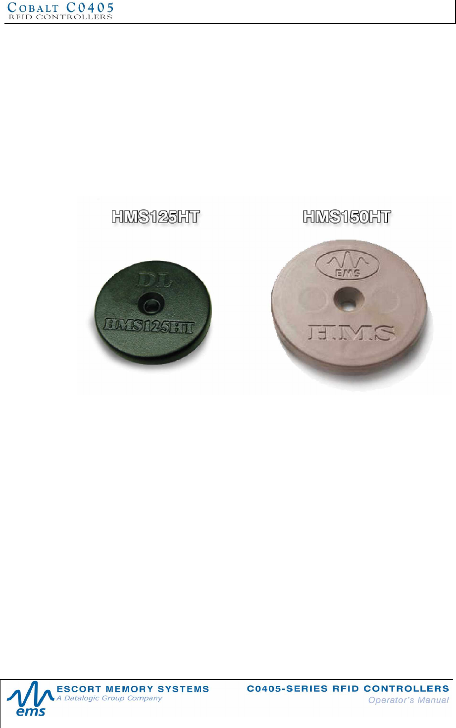
5.2.1 HMS-Series Tags
• Philips Mifare Classic, 1k-byte* + 32-bit ID (ISO 14443A)
*Mifare 1 kilobyte total IC memory. Of this memory, 736-bytes are available for user data.
• Philips Mifare Classic, 4k-byte** + 32-bit ID (ISO 14443A)
**Mifare 4 kilobytes total IC memory. Of this memory, 3,440-bytes are available for user data.
Figure 5-1: HMS125HT and HMS150HT tags
CHAPTER 5: RFID TAGS
P/N: 17-1328 REV 02 (08/07) PAGE 46 OF 83
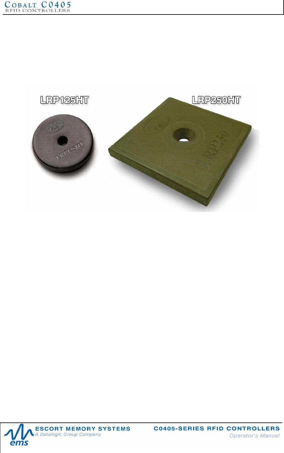
5.2.2 LRP-Series Tags
§ Philips I-CODE 1, 48-byte + 64-bit ID
§ Philips I-CODE SLi, 112-byte + 64-bit ID (ISO 15693)
§ Texas Instruments Tag-it, 32-byte + 64-bit ID (ISO 15693)
§ Infineon My-D Vicinity, 1k-byte + 64-bit ID (ISO 15693)
Figure 5-2: LRP-Series Tags
The HMS-Series and LRP-Series RFID tags listed in the above section are passive
devices, meaning that they require no internal batteries. These tags are fully readable
and writeable, except for the tag’s unique ID number, which is read only.
There are no serviceable or repairable parts inside these tags, yet most are capable
of providing over 100,000 write cycles and 10 years of data retention. In fact, tests
resulting in over one million write cycles have been recorded by some tags.
Numerous tag-related factors can adversely affect RF range and data transmission
between the controller and the tag, including the tag’s integrated circuit (IC), the tag’s
antenna coil design, the tag’s antenna conductor material, the tag’s antenna coil
substrate, the tag IC incorporated, the antenna coil bonding process and the
embodiment material that is used.
Additionally, the mounting environment of the tag and reader/writer can hinder
performance due to other materials affecting the tuning of either antenna. Escort
Memory Systems has performed extensive testing to produce tags that obtain
optimum performance with our RFID devices. In most cases, optimal range will be
obtained when mounting the tag and antenna in locations free from the influence of
metals and EMI emitting devices.
CHAPTER 5: RFID TAGS
P/N: 17-1328 REV 02 (08/07) PAGE 47 OF 83
5.3 TAG EMBODIMENTS
RFID tags are designed, produced and distributed in a variety of sizes and packages.
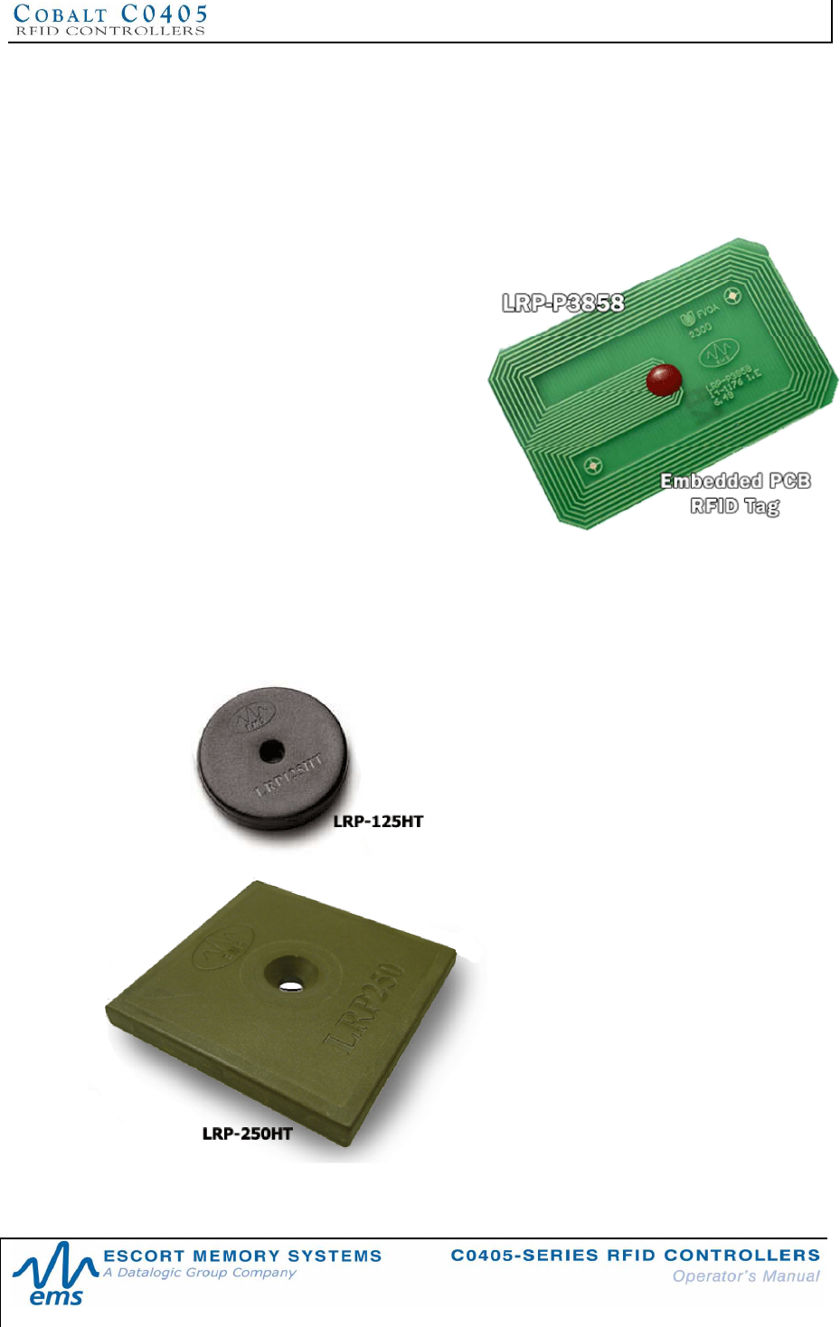
5.3.1 Printed Circuit Board RFID Tags
RFID tags that incorporate Printed
Circuit Board technology are designed
for encasement inside totes, pallets, or
products that can provide the protection
normally associated with injection-
molded enclosures.
These tags are made primarily from
etched copper PCB materials (FR-4, for
example) and are die-bonded by means
of high quality wire bonding. This
procedure ensures reliable electrical
connections that are superior to flip-chip
assembly methods. The RFID tag’s
integrated circuit is then encapsulated
in epoxy to protect it and the electrical
connections.
5.3.2 Molded RFID Tags
Molded tags utilize PCB tags and are the most rugged and reliable of the tags offered
by Escort Memory Systems. These tags are designed for closed-loop applications
where the tag is reused; thereby the cost of the tag can be amortized over the life of
the production line. Typically, molded
tags will be mounted to a pallet or
carrier that transports (and
accompanies) the product through the
entire production process. Other
applications for these tags include (but
are not limited to) embedding tags
within concrete floors for location
identification, shelf identification for
storage and retrieval systems, and tool
identification.
Escort Memory Systems offers a wide
variety of molded tags that have been
developed over the years for real world
applications. High temperature tags
using patented processes and
specialized materials allow tags to
survive elevated temperatures, such as
those required for automotive paint and
plating applications.

CHAPTER 5: RFID TAGS
P/N: 17-1328 REV 02 (08/07) PAGE 48 OF 83
5.4 TAG MEMORY
Tag memory addressing begins at address zero (0x0000), with the highest
addressable memory location equal to one less than the total number of bytes in the
tag. Each address is equal to one byte (8-bits), where the byte is the smallest
addressable unit of data. So for example, writing 8-bytes to a tag beginning at
address 0 will fill addresses 0 to 7 with 64-bits of data in all.
Depending on the manufacturer, RFID labels, molded tags and embedded PCBs can
have differing memory storage capacities and organization. Tag memory is grouped
into blocks of bytes that can vary in organization from manufacturer to manufacturer.
Even when compliant to ISO standards, byte memory addressing can differ from one
manufacturer to another (for example, tag memory can be organized in blocks of 4 or
8 bytes, depending on the RFID IC). Additionally, a certain number of bytes may be
allocated for storage of security data. For more information regarding a specific RFID
tag’s memory allocation, please refer to the IC manufacturer’s published datasheets.
Escort Memory Systems has taken great care to simplify tag memory addressing.
The mapping from logical address to physical address is handled by the C0405-
Series Controller’s operating system. Users only need to identify the starting address
location on the tag and the number of bytes to be read or written. However, extra
attention needs to be paid to the memory block structure when memory lock
commands are used. When data is locked, it cannot be altered. Caution should be
exercised when using memory lock commands as locked data cannot be unlocked,
even by Escort Memory Systems.
5.4.1 Mapping Tag Memory
Is it a Byte or a Bit?
Customers need to take into account that there are some RFID tag manufacturers
that measure and specify their tag memory sizes by the total number of bits, as this
method generates a much larger (8X) overall number designed to inflate their
specifications. Escort Memory Systems, on the other hand, prefers to specify total tag
memory sizes in terms of bytes (rather than in bits), as this method more closely
reflects how data is stored and retrieved from a tag and is typically what our
customers really want to know.
5.4.2 Creating an RFID Tag Memory Map
Creating a tag memory map is much like creating a spreadsheet that outlines the
actual data you plan to capture as well as the specific tag memory locations in which
you wish to store said data. Tag memory maps should be carefully planned, simple
and straightforward. It is advisable to utilize more storage space than is initially
required, as inevitably a need will arise to hold more data.
CHAPTER 5: RFID TAGS
P/N: 17-1328 REV 02 (08/07) PAGE 49 OF 83
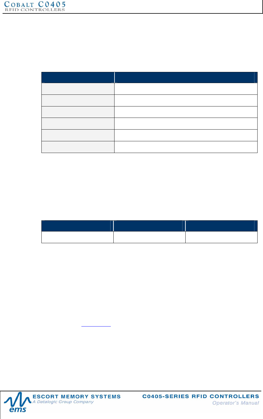
TA G MEMORY MA P - EXAMPLE
In the example below, 90-bytes of a 112-byte tag have been allocated to areas of the
memory map (leaving roughly 20% free for future uses). Because a short paragraph
of alphanumeric characters could quickly use all 90 bytes, creating an efficient
mapping scheme, which utilizes all 720-bits out of the 90-bytes allocated, will provide
a better use of tag space.
TAG ADDRESS DESCRIPTION OF USAGE
00 - 15 Serial Number
16 - 47 Model Number
48 - 63 Manufacturing Date
64 - 71 Lot Number
72 - 89 Factory ID
90 - 111 Reserved
Table 5-1: Tag Memory Map Example
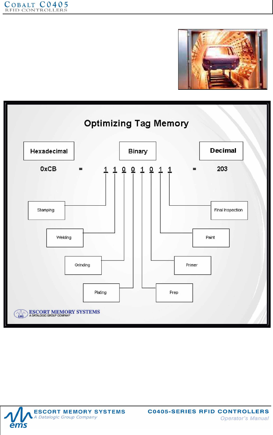
5.4.3 Optimizing Tag Memory
It should first be understood that data is always stored in tag memory in a binary form
(1’s and 0’s). Binary numbers are notated using the hexadecimal numbering system
(otherwise it would be too confusing looking at a screen full of 1’s and 0’s).
Below is an example of how hexadecimal notation simplifies the expressing of byte
values for the decimal number 52,882.
DECIMAL BINARY HEXADECIMAL
52,882 1100111010010010 CE92
In the above example, instead of using 5-bytes of data to store the ASCII bytes
representing characters 5, 2, 8, 8, and 2 (ASCII bytes: 0x35, 0x32, 0x38, 0x38, 0x32)
by simply writing two Hex bytes (0xCE and 0x92), 60% less tag memory is used to
store the same information.
When an alphabetical character is to be written to a tag, the ASCII value of the given
character is written to the tag. For example, to write a capital “D” (ASCII value 0x44),
the binary equivalent of the ASCII character 0x44 is written to the tag.
Additionally, if a database with look up values is used in the RFID application, the
logic level of the individual bits in the tag can be used to maximize tag memory.
(Note: refer to Appendix D in this document for a complete chart of ASCII characters
and their corresponding Hex values).
CHAPTER 5: RFID TAGS
P/N: 17-1328 REV 02 (08/07) PAGE 50 OF 83
OPTIMIZING TAG MEMORY - EXAMPLE
The graphic below illustrates how a single byte
(8-bits) can be efficiently used to track an
automobile’s inspection history at eight
inspection stations.
The number one (1) represents a required
operation and the number zero (0) represents
an operation that is not required for that
particular vehicle.
Figure 5-3: Optimizing Tag Memory
CHAPTER 6: COMMAND PROTOCOLS
P/N: 17-1328 REV 02 (08/07) PAGE 51 OF 83
CHAPTER 6:
COMMAND PROTOCOLS
6.1 ABXCOMMAND PROTOCOL OVERVIEW
When an RFID command is issued, the host computer instructs the RFID controller to
perform a given task. After performing that task, the RFID controller will normally
reply back with a Command Response message indicating the status or results of the
attempted command. This response notifies the host as to whether the command
was successfully completed or if the RFID controller failed to complete the command.
To understand and execute RFID commands, the C0405 and the host must be able
to communicate using the same language. The language that is used to
communicate RFID commands is referred to as the Command Protocol. The type of
Command Protocol that is used is known as the ABx Command Protocol, of which
there are three primary variations. The three versions of the ABx Command Protocol
that are supported by the C0405-Series RFID Controller are:
•ABx Fast (default)
•ABx ASCII
•ABx Standard
The ABx Fast Command Protocol has a single-byte based packet structure that
permits the execution of RFID commands while requiring the transfer of fewer total
bytes than ABx ASCII and ABx Standard. ABx Fast is the default command protocol
used by C0405 RFID Controllers. It can be used with or without a checksum byte.
The ABx ASCII Command Protocol also has a single-byte based packet structure
that supports the execution of RFID commands using the seven-bit ASCII character
set. By preventing data from interrupting communications when an ASCII control
character is received, ABx ASCII can be useful in applications where flow control is
required. This protocol can also be used with or without a checksum.
The ABx Standard Command Protocol uses a double-byte, word based format that
shares a common syntax with most existing RFID systems produced by Escort
Memory Systems. This protocol offers legacy support, which may be required by
existing PLC applications that only support a 2-byte word packet format. If your
application requires compatibility with existing or legacy RFID devices from Escort
Memory Systems’, use ABx Standard. ABx Standard does not support the use of a
checksum byte.
NOTE:
By default, the C0405 is configured to use the ABx Fast Command Protocol. ABx Fast
(as the name suggests) is the faster and more efficient of the three ABx protocols,
offering increased communication speed and error immunity.
CHAPTER 6: COMMAND PROTOCOLS
P/N: 17-1328 REV 02 (08/07) PAGE 52 OF 83
6.1.1 ABx Command Structures
All ABx-based RFID commands contain certain fundamental packet elements,
including a Command Header, a Command ID, one or more Command
Parameters (when applicable) and a Command Terminator.
Command Packet Structure = [Command Header + Command ID + Command Parameters
+ Command Terminator]
6.1.2 ABx Protocols - Headers and Terminators
In ABx Standard, commands begin with the one-byte command header "0xAA," and
end with the two-byte command terminator "0xFF, 0xFF".
In ABx Fast and ABx ASCII, commands begin with the two-byte command header
“0x02, 0x02” and end with the one-byte command terminator “0x03.”
See the table below for further clarification.
ABx Protocols - Headers and Terminators
ABX PROTOCOL HEADER TERMINATOR
ABx Fast 0x02, 0x02 0x03
ABx ASCII 0x02, 0x02 0x03
ABx Standard 0xAA 0xFF, 0xFF
Table 6-1: ABx Protocols - Headers and Terminators
When a command is issued by the host, the RFID controller stores the incoming data
packet in a buffer while it scans the data for a start character (0x02, 0x02 or 0xAA).
When a start character is found, it checks for the proper terminator (0x03 or 0xFF,
0xFF). Having identified a potentially valid command string, the controller will verify
the format of the data and either perform the requested function or generate an error
message.
6.1.3 ABx Response Structures
After completing an ABx command, the C0405 generates a host-bound, response
packet that indicates the status and/or results of the attempted command. The
response packet structure for all ABx protocols consists of a Response Header, a
Command Echo, one or more Response Values (when applicable), and a
Response Terminator.
Response Packet Structure = [Response Header + Command Echo + Response Values +
Response Terminator]
Note that for each ABx protocol, response header and response terminator
parameters are the same as their command header and command terminator
counterparts.
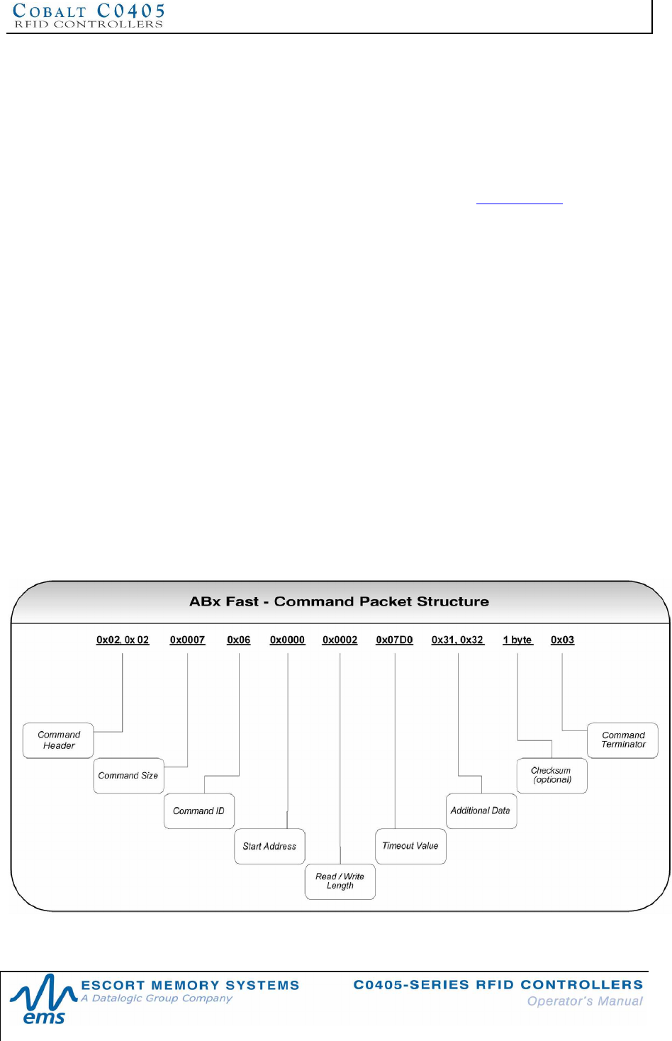
CHAPTER 6: COMMAND PROTOCOLS
P/N: 17-1328 REV 02 (08/07) PAGE 53 OF 83
6.2 ABXFAST COMMAND PROTOCOL
The default command protocol used by C0405-Series RFID Controllers for Point-to-
Point data transmission is known as the ABx Fast Command Protocol. ABx Fast
has a single-byte oriented packet structure that permits the rapid execution of RFID
commands while requiring the transfer of a minimal number of bytes.
ABx Fast supports the inclusion of an optional checksum byte. When increased data
integrity is required, the checksum should be utilized. See Section 6.2.4 for more on
using the checksum parameter.
6.2.1 ABx Fast - Command / Response Procedure
After an RFID command is issued by the host, a packet of data, called the
“Command Packet” is sent to the controller. The command packet contains
information that instructs the controller to perform a certain task.
The controller automatically parses the incoming data packet, searching for a specific
pair of start characters, known as the “Command Header.” In ABx Fast, the
Command Header / Start Characters are 0x02, 0x02. When a valid Command
Header is recognized, the controller then checks for proper formatting and for the
presence of a Command Terminator byte. In ABx Fast, the Command Terminator
byte is 0x03.
Having identified a valid command, the controller will attempt to execute the given
instructions. After which the controller will generate a host-bound response message
containing EITHER the results of the attempted command or an error code if the
operation failed.
Note that all commands generate a response from the controller. Before sending a
second or additional command to a C0405, allow the host to first process (remove
from memory) any pending response data.
Figure 6-1: ABx Fast - Command Packet Structure
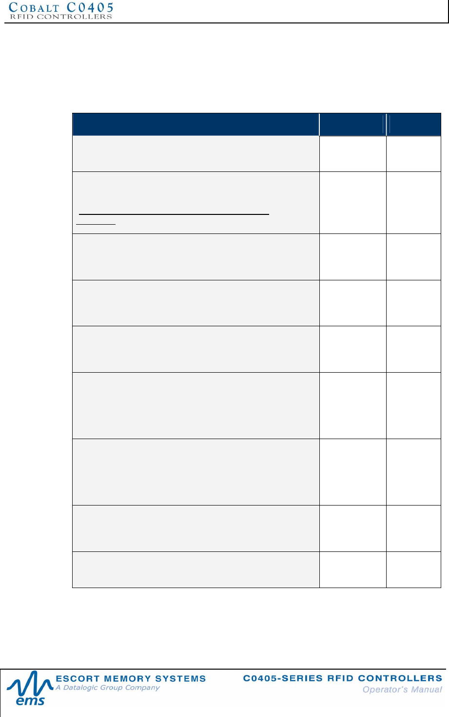
CHAPTER 6: COMMAND PROTOCOLS
P/N: 17-1328 REV 02 (08/07) PAGE 54 OF 83
6.2.2 ABx Fast - Command Packet Structure
The packet structure of all ABx Fast command contains certain basic elements,
including Command Header, Command Size, Command ID and Command
Terminator. Additional options are available depending on the command being
performed.
COMMAND PACKET ELEMENT CONTENT SIZE
COMMAND HEADER:
The first two bytes of an ABx Fast command packet
0x02, 0x02 2 bytes
COMMAND SIZE:
This 2-byte integer defines the number of bytes in the packet
(excluding header, command size, checksum and
terminator).
0x0007 +
(number of
bytes of
additional
data)
2-byte
integer
COMMAND ID:
This single-byte value indicates the RFID command to
execute.
0x06
(Write Data)1 byte
START ADDRESS:
This two-byte parameter indicates the location of tag memory
where a read or write operation shall begin.
0x0000 2-byte
integer
READ/WRITE LENGTH:
This two-byte parameter represents the number of bytes that
are to be retrieved from or written to the RFID tag.
0x0001 2-byte
integer
TIMEOUT VALUE:
This two-byte parameter indicates the maximum length of
time for which the controller will attempt to complete the
command. Measured in milliseconds, this value can have a
range of 0x0001 to 0xFFFE or between 1 and 65,534 msecs.
0x07D0
(0x07D0 =
2000 x .001 =
2 seconds)
2-byte
integer
ADDITIONAL DATA:
This parameter uses one byte to hold a single character for
fill operations and supports the use of multiple bytes when
several characters are needed for write commands (when
applicable).
0x00 One or
more bytes
(when
applicable)
CHECKSUM:
This optional parameter holds a single-byte checksum (only
applicable when using ABx Fast with Checksum).
Optional 1 byte
(when
applicable)
COMMAND TERMINATOR:
Single-byte command packet terminator (always 0x03)
0x03 1 byte
Table 6-2: ABx Fast - Command Packet Structure
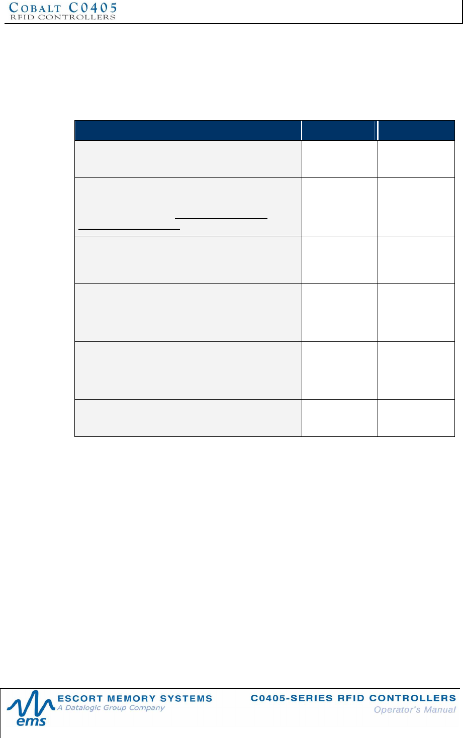
CHAPTER 6: COMMAND PROTOCOLS
P/N: 17-1328 REV 02 (08/07) PAGE 55 OF 83
6.2.3 ABx Fast - Response Packet Structure
After performing a command, the C0405, in most cases, will generate a host-bound
response packet. ABx Fast responses contain a Response Header, Response Size,
Command Echo, one or more Response Values (when applicable), and a
Response Terminator.
RESPONSE PACKET ELEMENT CONTENT SIZE
RESPONSE HEADER:
First two bytes of an ABx Fast response packet
0x02, 0x02 2 bytes
RESPONSE SIZE:
This two-byte integer defines the total number of bytes
in the response packet (excluding header, size,
checksum and terminator).
0x0001 2-byte integer
COMMAND ECHO:
The single-byte parameter identifies the command for
which the response packet was generated.
0x06 1 byte
RETRIEVED DATA:
This parameter is used to hold one or more bytes of
data that was requested by the command (when
applicable).
Data 1 or more bytes
(when
applicable)
CHECKSUM:
This optional parameter holds a single-byte checksum
(only applicable when using ABx Fast with
Checksum).
Optional 1 byte
(when
applicable)
RESPONSE TERMINATOR:
Single-byte response packet terminator (always 0x03)
0x03 1 byte
Table 6-3: ABx Fast - Response Packet Structure
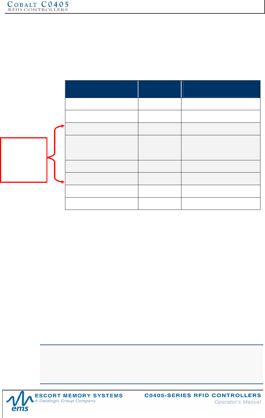
CHAPTER 6: COMMAND PROTOCOLS
P/N: 17-1328 REV 02 (08/07) PAGE 56 OF 83
6.2.4 ABx Fast - Command Packet Parameters
Command Size
The ABx Fast protocol requires that the byte count, known as the Command Size,
be specified as a two-byte integer. To calculate the command size, add the total
number of bytes within the command packet while excluding the header, command
size, checksum (if present) and terminator (see example below).
COMMAND ELEMENT # OF BYTES INCLUDED IN
COMMAND SIZE?
Command Header 2No
Command Size 2No
Command ID 1Yes
Start Address 2Yes
Read/Write Length 2Yes
Timeout Value 2Yes
Additional Data Bytes 1Yes
Checksum 1No
Command Terminator 1 No
The command size for this example is 0x0008.
Start Address
The Start Address parameter holds a two-byte integer representing the tag memory
address location where a read or write operation will begin.
Read/Write Length
The two-byte Read/Write Length integer indicates the number of bytes that are to be
read from or written to the RFID tag.
Timeout Value
A two-byte Timeout Value parameter (measured in one-millisecond increments) is
used to set the length of time that the controller will attempt to complete the specified
operation.
The maximum supported timeout value is 0xFFFE or 65,534ms (slightly longer than
one minute). Setting a long timeout length does not necessarily mean that a
command will take any longer to execute. This value only represents the period of
time for which the controller will attempt to complete the command.
IMPORTANT:
During write commands, the tag must remain within the antenna’s RF field until the
write operation completes successfully, or until the timeout value has expired. If a write
operation is not completed before the tag leaves the controller’s RF field, data may be
incompletely written.
Command
Size =
number of
bytes in these
fields
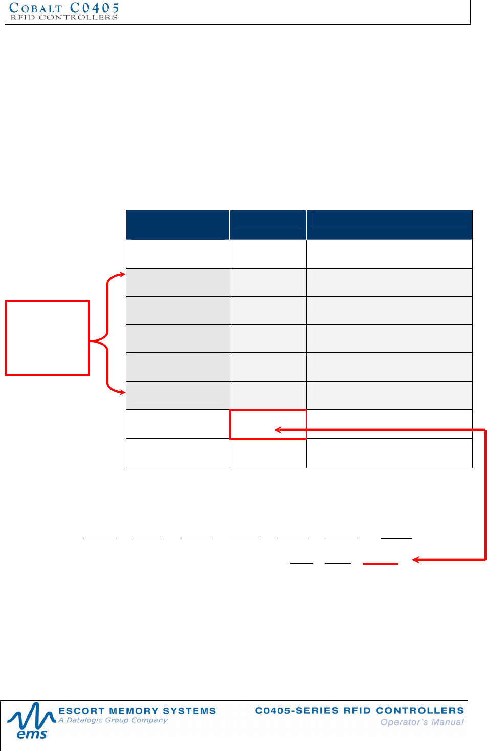
CHAPTER 6: COMMAND PROTOCOLS
P/N: 17-1328 REV 02 (08/07) PAGE 57 OF 83
Checksum
ABx Fast and ABx ASCII Command Protocols support the inclusion of an additional
checksum byte that is used to verify the integrity of data being transmitted between
host and controller.
The checksum is calculated by adding together (summing) the byte values in the
command packet (less the header, checksum and terminator), and then subtracting
the total byte sum from 0xFF. Therefore, when the byte values of each packet
element (from command size to checksum) are added together, the byte value sum
will equal 0xFF.
CHECKSUM EXAMPLE
The following example depicts Command 0x05 (Read Data) using a checksum.
COMMAND
ELEMENT CONTENTS USED IN CHECKSUM
Command Header 0x02, 0x02 n/a
Command Size 0x0007 0x00, 0x07
Command ID 0x05 0x05
Start Address 0x0001 0x00, 0x01
Read Length 0x0004 0x00, 0x04
Timeout Value 0x07D0 0x07, 0xD0
Checksum 0x17 n/a
Command Terminator 0x03 n/a
Add the byte values from the command size, command ID, start address, read length
and timeout value parameters together and subtract from 0xFF. Resulting value will
be the checksum.
[0x07 + 0x05 + 0x01 + 0x04 + 0x07 + 0xD0] = 0xE8
The checksum equation is: [0xFF – 0xE8] = 0x17
Checksum =
[0xFF – (sum
of these
fields)]
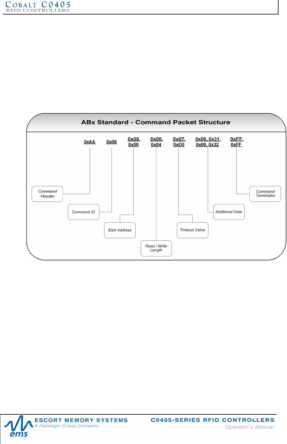
CHAPTER 6: COMMAND PROTOCOLS
P/N: 17-1328 REV 02 (08/07) PAGE 58 OF 83
6.3 ABXSTANDARD COMMAND PROTOCOL
The ABx Standard Command Protocol is a binary, double-byte, “word” oriented
protocol where data is transmitted in 2-byte increments: a Most Significant Byte
(MSB) or “High Byte” and a Least Significant Byte (LSB) or “Low Byte”.
For ABx Standard commands, the first data word sent to the controller contains the
command header and command ID, followed by parameters such as start address,
read/write length and timeout value.
Note that at no time can the complete command packet string (including terminator)
exceed 50 words or 100 bytes.
Figure 6-2: ABx Standard - Command Packet Structure
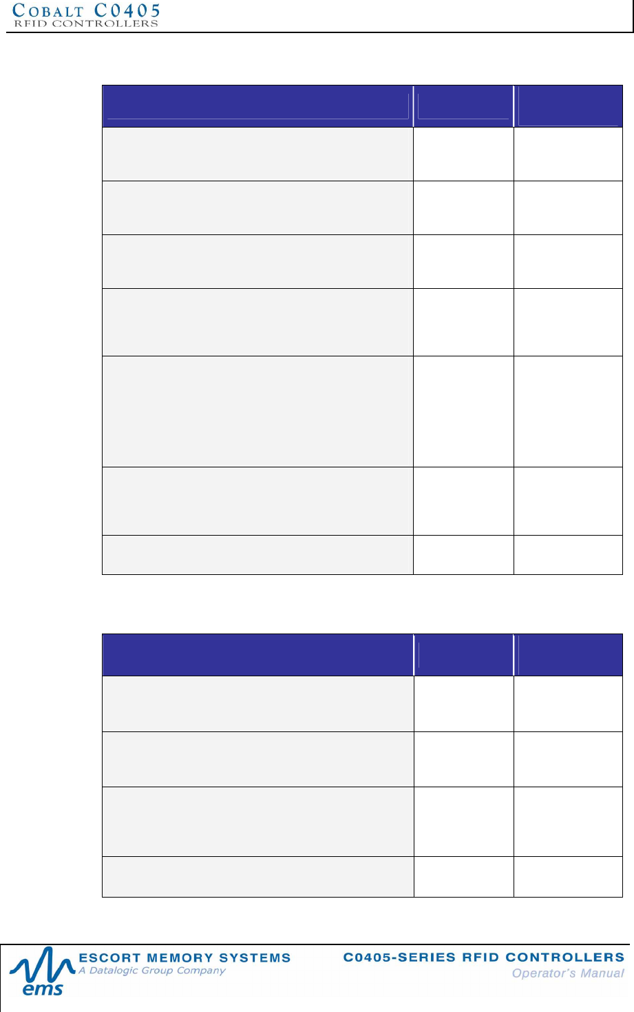
CHAPTER 6: COMMAND PROTOCOLS
P/N: 17-1328 REV 02 (08/07) PAGE 59 OF 83
6.3.1 ABx Standard - Command Packet Structure
COMMAND PACKET ELEMENT CONTENT BYTE
COUNT
COMMAND HEADER:
0xAA is always the MSB of the first word of an ABx
Standard command.
0xAA 1
COMMAND ID:
The command ID is always the LSB of the first word
and indicates the RFID command to execute.
0x06
(Write Data)1
START ADDRESS:
This two-byte parameter indicates the location of tag
memory where a read or write operation shall begin.
0x0000 2
READ/WRITE LENGTH:
This two-byte parameter represents the number of
bytes that are to be retrieved from or written to the
RFID tag.
0x0001 2
TIMEOUT VALUE:
This two-byte integer indicates the maximum length of
time for which the controller will attempt to complete
the command. Measured in milliseconds, this value
can have a range of 0x0001 to 0xFFFE or between 1
and 65,534 msecs (0x07D0 = 2000 x .001 = 2
seconds).
0x07D0 2
ADDITIONAL DATA:
This parameter uses two bytes to hold a single
character (data to be written to the tag is included in
the LSB only, MSB = 0x00).
0x00, 0x00 2 (or more when
applicable)
TERMINATOR:
Double-byte command packet terminator
0xFF, 0xFF 2
Table 6-4: ABx Standard - Command Packet Structure
6.3.2 ABx Standard - Response Packet Structure
RESPONSE PACKET ELEMENT CONTENT BYTE
COUNT
RESPONSE HEADER:
0xAA is always the MSB of the first word of an ABx
Standard response packet
0xAA 1
COMMAND ECHO:
The command echo is always the LSB of the first word
and indicates the RFID command that was executed.
0x06
(Write Data)2
ADDITIONAL DATA:
This parameter uses two bytes to hold a single
character of retrieved data (data is returned in the LSB
only, MSB = 0x00).
0x00, 0x00 2 (or more when
applicable)
TERMINATOR:
Double-byte command packet terminator
0xFF, 0xFF 2
Table 6-5: ABx Standard - Response Packet Structure
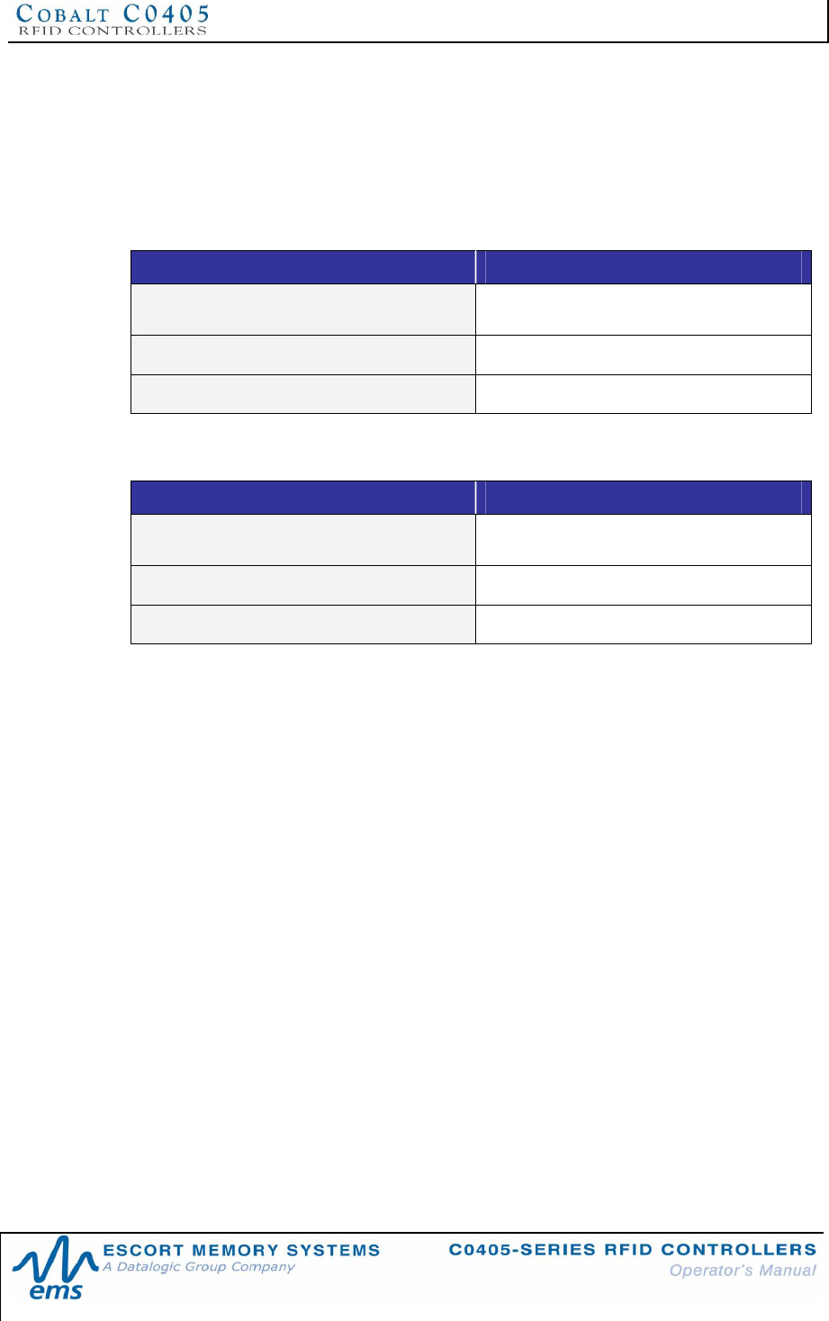
CHAPTER 6: COMMAND PROTOCOLS
P/N: 17-1328 REV 02 (08/07) PAGE 60 OF 83
6.3.3 ABx Standard - Command Example
The example below depicts the packet structure of the ABx Standard command and
response messages for Command 0x08 (Tag Search). In this example, the RFID
controller is instructed to search for a tag in the RF field. A Timeout Value of two
seconds (0x07D0) is set for the completion of this operation.
Command from Host
COMMAND ELEMENT CONTENT
Header and Command ID (MSB/LSB) 0xAA, 0x08 (Tag Search)
Timeout Value 0x07D0
Terminator 0xFF, 0xFF
Response from Controller
RESPONSE ELEMENT CONTENT
Header and Command ID (MSB/LSB) 0xAA, 0x08 (Tag Search)
Timeout 0x07D0
Terminator 0xFF, 0xFF
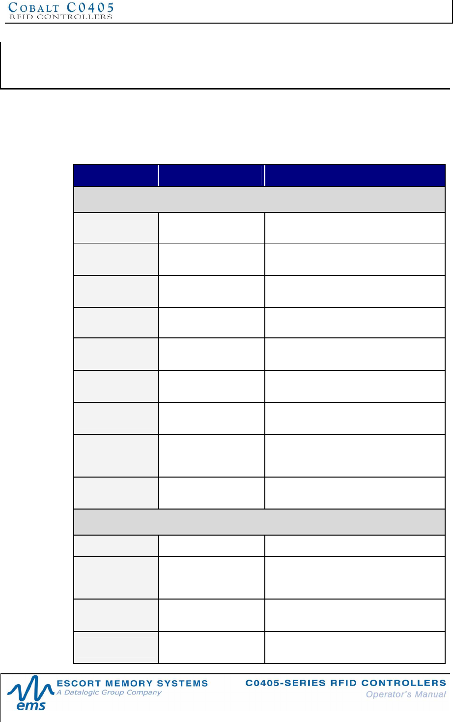
CHAPTER 7: RFID COMMANDS AND ERROR CODES
P/N: 17-1328 REV 02 (08/07) PAGE 61 OF 83
CHAPTER 7:
RFID COMMANDS AND ERROR CODES
7.1 ABXFAST RFID COMMAND TABLE
The table below lists the ABx Fast RFID commands supported by C0405-Series
RFID Controllers.
COMMAND ID COMMAND NAME DESCRIPTION
Single-Tag RFID Commands
0x04 Fill Tag Fills a specified tag address range with a
one-byte value
0x05 Read Data Reads a specified length of data from a
contiguous (sequential) area of tag memory
0x06 Write Data Writes a specified number of bytes to a
contiguous area of tag memory
0x07 Read Tag ID Retrieves a tag’s unique identification (Tag
ID) number
0x08 Tag Search Instructs the controller to search for a tag in
its RF field
0x0D Start
Continuous
Read Instructs the controller to start or stop
Continuous Read mode.
0x0E Read Tag ID and
Data Reads a tag’s ID number as well as a
specified number of bytes of tag memory
0x0F Start
Continuous
Read Tag ID and
Data
Instructs the controller to start or stop
Continuous Read Tag ID and Data mode.
0x27 Lock Memory
Block Write protects a block of tag memory
RFID Controller Commands
0x35 Reset Controller Resets power to the controller
0x36 Set Controller
Configuration
Used to set (configure or modify) the
controller’s configuration parameters and
settings
0x37 Get Controller
Configuration Retrieves the controller’s configuration
settings
0x38 Get Controller
Info Retrieves hardware, firmware and serial
number information from the controller
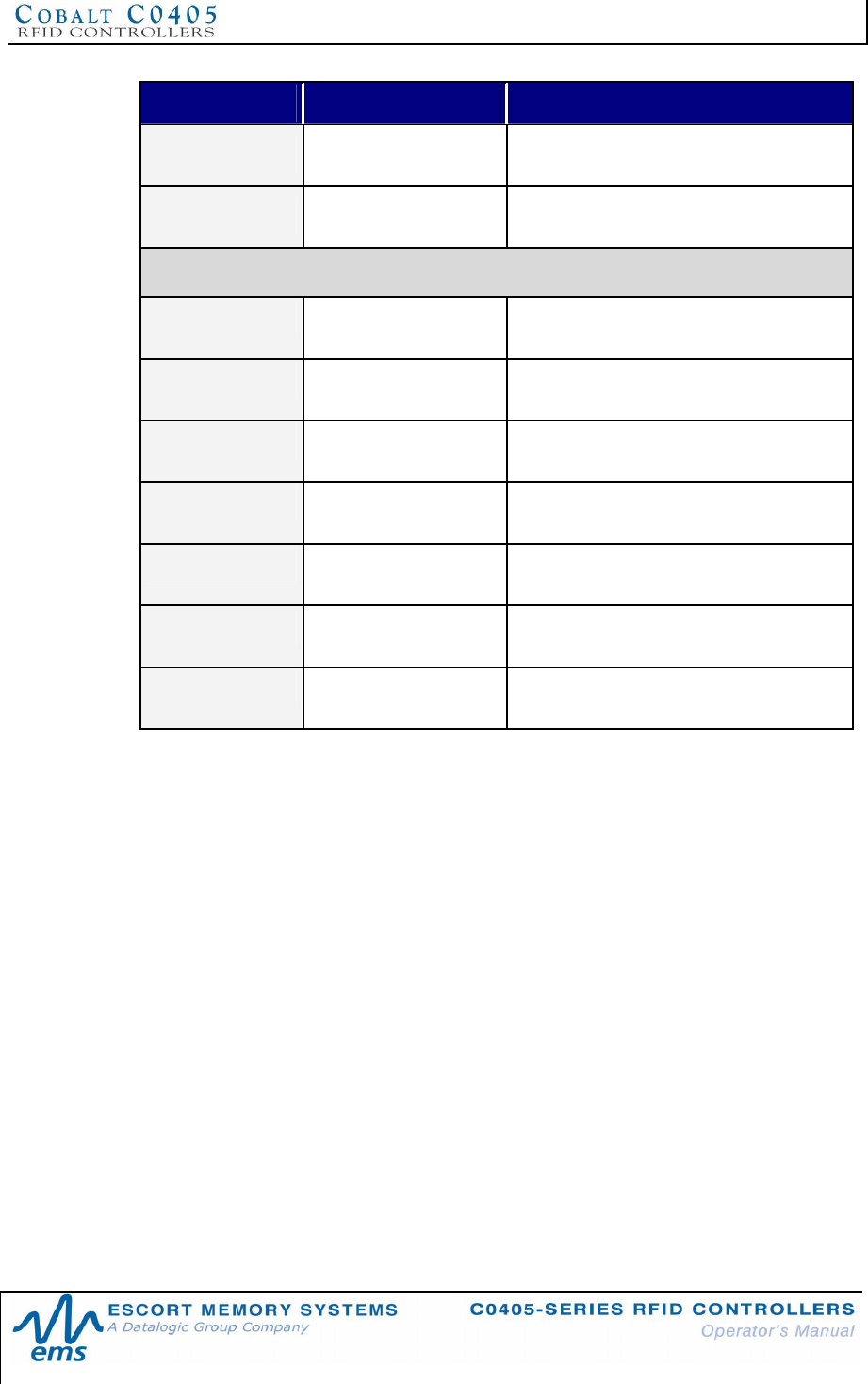
CHAPTER 7: RFID COMMANDS AND ERROR CODES
P/N: 17-1328 REV 02 (08/07) PAGE 62 OF 83
COMMAND ID COMMAND NAME DESCRIPTION
0x51 Set Controller
Time Used to set the time for the controller
0x72 Execute
Controller Macro Instructs the controller to execute one of its
eight macros
Multi-Tag RFID Commands
0x82 Multi-Tag Read
ID and Data All Retrieves a contiguous segment of data and
the tag ID from all RFID tags in range
0x85 Multi-Tag Block
Read All Retrieves a contiguous segment of data
from all RFID tags in range
0x86 Multi-Tag Block
Write All Writes a contiguous segment of data to all
RFID tags in range
0x87 Multi-Tag Get
Inventory Retrieves the tag ID from all RFID tags in
range
0x88 Multi-
Tag Search
All Checks for the presence of any RFID tags
in range
0x95 Multi-Tag Block
Read by ID Reads a contiguous segment of data from a
specific RFID tag identified by its tag ID
0x96 Multi-Tag Block
Write by ID Writes a contiguous segment of data to a
specific RFID tag identified by its tag ID
Table 7-1: ABx Fast RFID Command Table
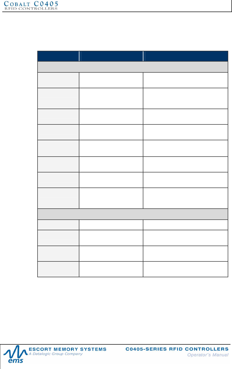
CHAPTER 7: RFID COMMANDS AND ERROR CODES
P/N: 17-1328 REV 02 (08/07) PAGE 63 OF 83
7.2 ABXSTANDARD RFID COMMAND TABLE
The table below lists the ABx Standard RFID commands supported by C0405-Series
RFID Controllers.
COMMAND ID COMMAND NAME DESCRIPTION
RFID Tag Commands
0x04 Fill Tag Fills a specified tag address range with
a one-byte value
0x05 Read Data Reads a specified number of bytes from
a contiguous (sequential) length of tag
memory
0x06 Write Data Writes a specified number of bytes to a
contiguous length of tag memory
0x07 Read Tag ID Retrieves a tag’s unique identification
(Tag ID) number
0x08 Tag Search Instructs the controller to search for a
tag in its RF field
0x0D Start Continuous
Read Instructs the controller to start and stop
Continuous Read mode.
0x0E Read Tag ID and
Data Retrieves the tag ID and a specified
number of bytes from the tag
0x0F Start Continuous
Read Tag ID and
Data
Instructs the controller to start and stop
Continuous Read Tag ID and Data
mode.
RFID Controller Commands
0x35 Reset Controller Resets power to the controller
0x36 Set Controller
Configuration Used to modify and update the
configuration settings of the controller
0x37 Get Controller
Configuration Retrieves configuration settings from the
controller
0x38 Get Controller Info Retrieves hardware, firmware and serial
number information from the controller
Table 7-2: ABx Standard RFID Command Table
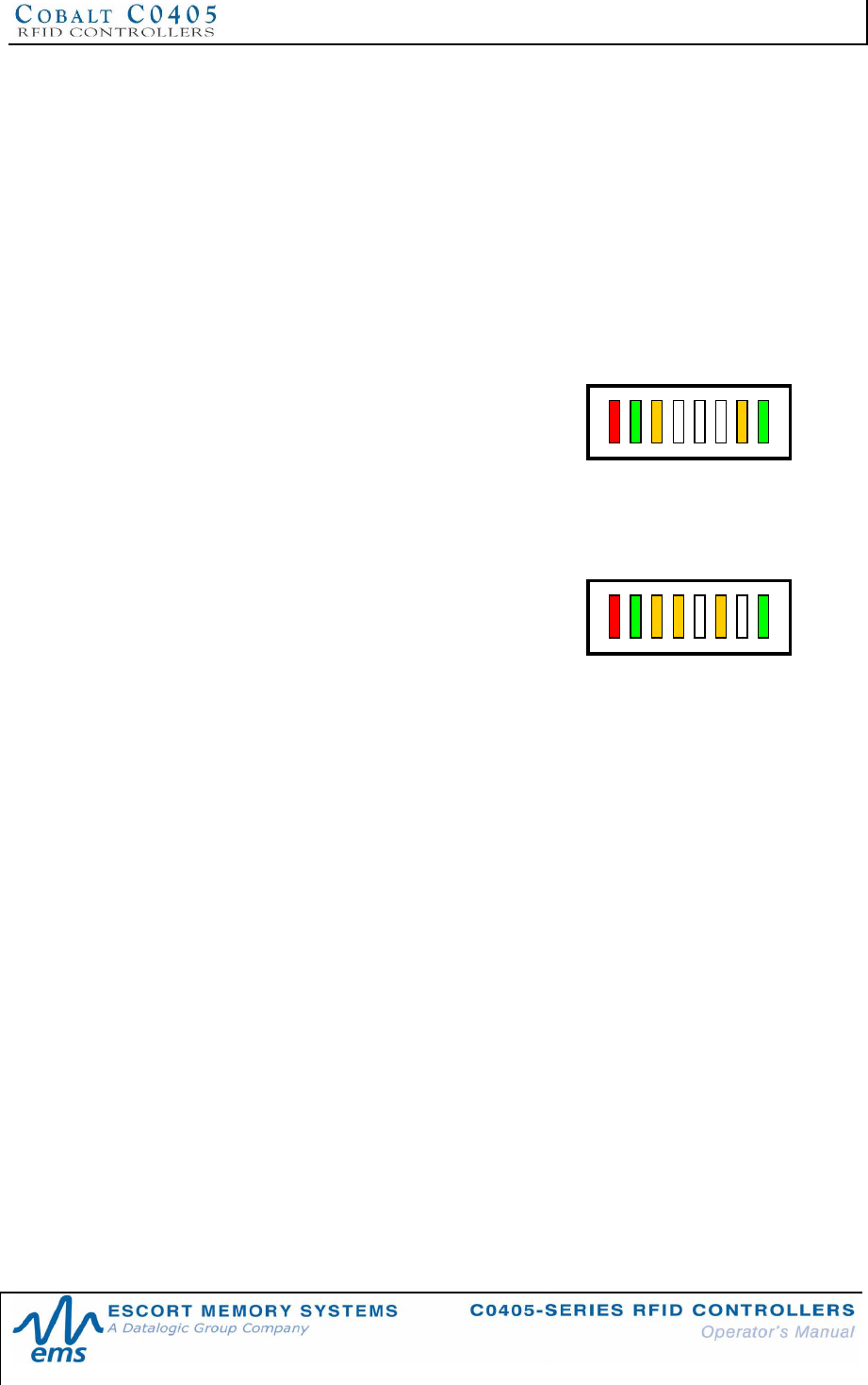
CHAPTER 7: RFID COMMANDS AND ERROR CODES
P/N: 17-1328 REV 02 (08/07) PAGE 64 OF 83
7.3 ERROR CODES
If the C0405 encounters a fault during operation, it will generate a response that
includes a one-byte ABx error code. Entering an invalid Start Address for a Read
Data command, for example, will generate ABx Error Code 0x32 (Invalid
Programming Address).
To display the single-byte error code in binary, the two left-most amber Node LEDs
(LED 24and LED 23) represent the first or most significant digit (MSD) of the error
code. The three remaining amber Node LEDs (LED 22, LED 21and LED 20) are
combined to represent the second or least significant digit (LSD) of the error code.
Examples:
•If the five amber Node LEDs (from L to R) =
ON, OFF, OFF, OFF, ON, the first digit of the
error code is a “2 “ and the second digit is a
“1,” meaning that error code 0x21 occurred
(error code 0x21 = command syntax error).
•If the five amber Node LEDs (from L to R) =
ON, ON, OFF, ON, OFF, the first digit of the
error code is a “3 “ and the second digit is a
“2,” meaning that error code 0x32 occurred
(error code 0x32 = invalid programming
address).
The RF LED and amber Node LEDs will continue to flash until a valid command is
received by the controller. The green COM LED will remain ON to help orient the
binary LED positions. If an unrecoverable error occurs, the LEDs will continuously
flash the error code until the C1007 has been reset.
P
W
R
242321
2220
C
O
M
R
F
P
W
R
242321
2220
C
O
M
R
F
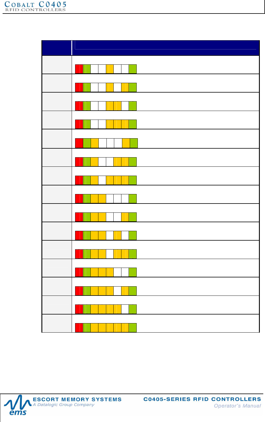
CHAPTER 7: RFID COMMANDS AND ERROR CODES
P/N: 17-1328 REV 02 (08/07) PAGE 65 OF 83
7.4 ABXERROR CODE TABLE
ERROR
CODE DESCRIPTION
0x04 Fill Operation not Completed
0x05 Read Operation not Completed
0x06 Write Operation not Completed
0x07 Read Tag ID Operation not Completed (Tag not Found)
0x21 Command Syntax Error
0x23 Unsupported Tag Type / Unsupported RF Command
0x27 Memory Lock Operation not Complete (memory may be locked)
0x30 Internal Error, Buffer Overflow
0x31 Invalid Controller Type
0x32 Invalid Programming Address
0x33 Invalid CRC Value
0x34 Invalid Software Version
0x35 Invalid Reset
0x36 Set Configuration Operation not Completed
0x37 Get Configuration Operation not Completed
Table 7-3: ABx Error Codes
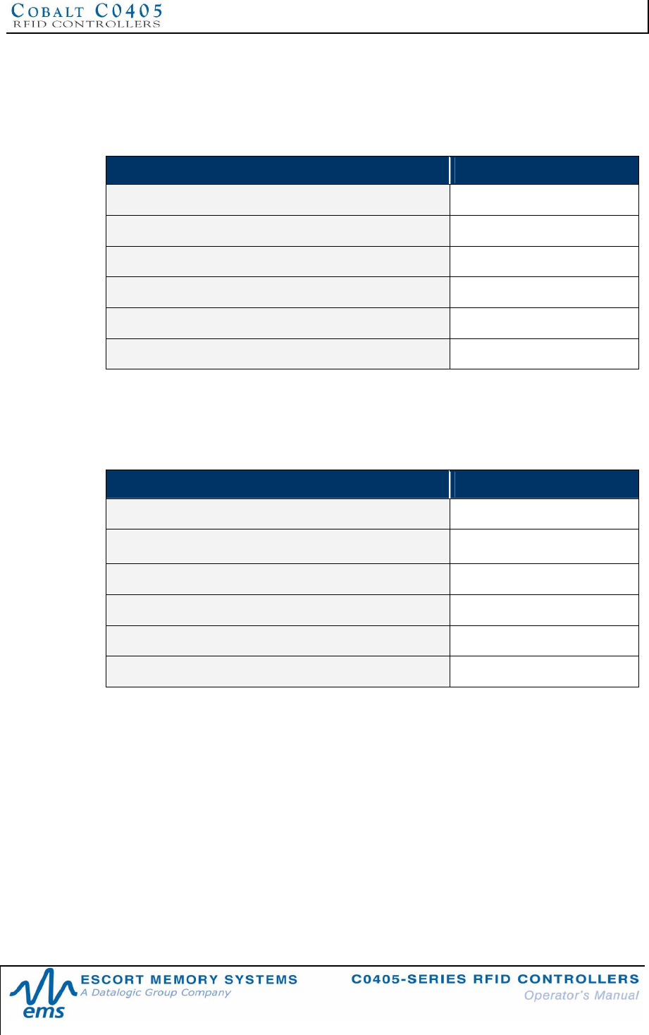
CHAPTER 7: RFID COMMANDS AND ERROR CODES
P/N: 17-1328 REV 02 (08/07) PAGE 66 OF 83
7.5 ABXFAST ERROR RESPONSE STRUCTURE
ABx Fast error responses contain a two-byte Header, a two-byte Response Size
parameter followed by a single-byte Error Flag (0xFF) and a single-byte Error Code
parameter, which identifies the error that occurred.
ERROR RESPONSE ELEMENT CONTENT
Header 0x02, 0x02
Response Size 0x0002
Error Flag 0xFF
Error Code Single-byte Error Code
Checksum Optional
Terminator 0x03
Table 7-4: ABx Fast - Error Response Structure
ABXFAST ERROR RESPONSE EXAMPLE
Below is an example of an ABx Fast error response for a failed Write Data command
(error code 0x06).
ERROR RESPONSE ELEMENT CONTENT
Header 0x02, 0x02
Response Size 0x0002
Error Flag 0xFF
Error Code 0x06
Checksum Optional
Terminator 0x03
CHAPTER 7: RFID COMMANDS AND ERROR CODES
P/N: 17-1328 REV 02 (08/07) PAGE 67 OF 83
7.6 ABXSTANDARD ERROR RESPONSE STRUCTURE
In ABx Standard, the error code will be returned in the LSB of the second word of the
response.
Below is the structure of an ABx Standard error response.
ERROR RESPONSE ELEMENT CONTENT (MSB/LSB)
Error Response Header (MSB/LSB) 0xAA, 0xFF
Error Code (MSB/LSB) 0x00, (1-byte error code value)
Terminator (MSB/LSB) 0xFF, 0xFF
Table 7-5: ABx Standard - Error Response Structure
ABXSTANDARD ERROR RESPONSE EXAMPLE
Below is an example of an ABx Standard error response message for a failed Write
Data operation (error code: 0x06).
ERROR RESPONSE ELEMENT CONTENT (MSB/LSB)
Error Response Header (MSB/LSB) 0xAA, 0xFF
Error Code (MSB/LSB) 0x00, 0x06
Terminator (MSB/LSB) 0xFF, 0xFF
APPENDIX A: TECHNICAL SPECIFICATIONS
P/N: 17-1328 REV 02 (08/07) PAGE 68 OF 83
APPENDIX A:
TECHNICAL SPECIFICATIONS
ELECTRICAL
Supply Voltage 10~30VDC
Power Consumption:
C0405-232-01 and C0405-485-01
2.4W (100mA @ 24VDC)
Power Consumption:
C0405-USB-01
1W (200mA @ 5VDC from USB bus)
COMMUNICATION
Communication Interfaces Point-to-Point: RS232, USB
Multi-drop, Subnet16, MUX32: RS485
RFID Interface Cobalt C0405-Series RFID System
RF Output Power 100mW
Air Protocols ISO 15693, ISO 14443A
Air Protocol Speed 26.5k Baud / 106k Baud with CRC error detection
RS232/RS485 Baud Rates 9600 (default), 19.2k, 38.4k, 57.6k, 115.2k
MECHANICAL
Dimensions 40mm x 56mm x 25mm (1.6in x 2.2in x 1in)
Weight 47g (1.7 oz)
Enclosure Polycarbonate
ENVIRONMENTAL
Operating Temperature -20° to 50°C (-4° to 122°F),
Storage Temperature -40° to 85°C (-40° to 185°)
Humidity 100%
Protection Class IP67
Shock Resistance IEC 68-2-27 Test EA 30g, 11ms, 3 shocks each axis
Vibration Resistance IEC 68-2-6 Test FC 1.5mm; 10 to 55Hz;
2 hours each axis
NOTE: Specifications are subject to change without notice.

APPENDIX A: TECHNICAL SPECIFICATIONS
P/N: 17-1328 REV 02 (08/07) PAGE 69 OF 83
C0405-SERIES RFID CONTROLLER DIMENSIONS
Figure A0-1: C0405-Series RFID Controller Dimensions
APPENDIX B: MODELS & ACCESSORIES
P/N: 17-1328 REV 02 (08/07) PAGE 70 OF 83
APPENDIX B:
MODELS & ACCESSORIES
Escort Memory Systems designs, manufactures and distributes a wide range of high
frequency (HF) RFID equipment, including RFID controllers, network interface
modules (Gateways and Hubs), RFID tags and the cables needed to make it all work.
This portion of the manual lists the products and accessories available for the C0405-
Series RFID product family. To purchase any of the items listed below contact your
EMS distributor, call us directly at (800) 626-3993 or visit our Web site:
http://www.ems-rfid.com. Please let us know if you have any questions.
EMS HARDWARE
C0405-Series RFID Controllers
There are three models of the C0405-Series RFID Controller:
§C0405-232-01
§C0405-485-01
§C0405-USB-01
Each C0405 unit ships with the following accessories:
EMS P/N QTY DESCRIPTION
00-3000 1 Configuration Tag for C0405 I-CODE SLI,
20-1940 2 Screws, (M4, 20 PPH SS 18-8\302)
20-5918 2 Hex Nuts, (M4 SS 18-8\302)
20-3910 2 Washers, Flat (M4, 12MM OD, 4.3MMID)
14-3137 1 Mounting Bracket for the C0405, NORYL, Black GTX830
Subnet16 Gateway Interface Modules
GWY-01-TCP-01
Subnet16™ TCP/IP Gateway
GWY-01-IND-01
Subnet16™ Industrial Ethernet Gateway
Subnet16 Hub Interface Modules
HUB-04-TCP-01
Subnet16™ 4-Port TCP/IP Hub
HUB-04-IND-01
Subnet16™ 4-Port Industrial Ethernet Hub
APPENDIX B: MODELS & ACCESSORIES
P/N: 17-1328 REV 02 (08/07) PAGE 71 OF 83
SOFTWARE & DEMONSTRATION KITS
Software Applications
Visit the Escort Memory Systems website (www.ems-rfid.com) for download
instructions.
Cobalt HF Dashboard Utility (for TCP/IP or Serial Connections)
Communicate in real time with one or more readers directly or via Multi-drop network.
Allows users to configure, monitor and control their RFID devices from anywhere on
their network.
C-Macro Builder
An easy to use GUI-driven utility that provides rapid development and implementation
of custom RFID command macros.
Demonstration Kits
00-1203
Gateway TCP Demo Kit (includes one GWY-01-TCP-01 TCP Gateway interface
module, one C0405-485-01 controller, one C1007-485-01 controller, one HF-0405-
485-01 controller, LRP125S, LRP250 and T7036 RFID tags, interface cables, display
board and power supply).
00-1217
C0405-USB-01 Demo Kit (includes one C0405-USB-01 controller, one CBL-1525
USB interface cable, one LRP108I tag, one LRP125VS tag and one T7036 tag).
00-1218
Conveyor Demo Kit (includes one GWY-01-IND-01 Industrial Gateway interface
module, one C0405-485-01 controller, one C1007-485-01 controller, one HF-CNTL-
485-01 controller, one HF-ANT-1010-01 antenna, one LRP108S tag, three LRP250S
tags, one LRP525S tag, two T5050 tags, three T7036 tags, interface cables and
power supply).
00-1219
Gateway C0405-485 Demo Kit (includes one GWY-01-TCP-01 TCP Gateway
interface module, three C0405-485-01 controllers, one HMS150 tag, one LRP125S
tag, interface cables, carrying case, display board and power supply).
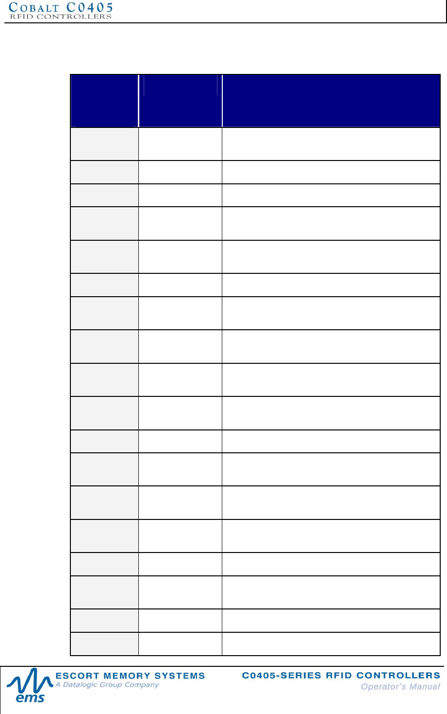
APPENDIX B: MODELS & ACCESSORIES
P/N: 17-1328 REV 02 (08/07) PAGE 72 OF 83
CABLE AND NETWORK ACCESSORIES
EMS P/N
XX =
LENGTH IN
METERS
COMPONENT DESCRIPTION
CBL-1478 Cable Assembly 8-pin, female M12 to RS232; with 2.5mm DC power
jack, 2m
CBL-1480-XX Cable 5-pin, male M12 to 5-pin, female M12 (ThinNet)
CBL-1481-XX Cable 5-pin, male M12 to 5-pin, male M12 (ThinNet)
CBL-1481-02 Cable 5-pin, male M12 to 5-pin, male M12, 2m (ThinNet,
Gateway to Drop-T)
CBL-1482-XX Cable 5-pin, male M12 to 5-pin, female, right-angle M12
(ThinNet)
CBL-1483-XX Cable 5-pin, male 7/8–16 to 5-pin, female 7/8-16 (ThickNet)
CBL-1484-XX Cable 5-pin, male, right-angle 7/8-16 to bare wire leads
(ThickNet)
CBL-1485 Drop-T Connector 5-pin, female 7/8-16 / female M12 / male 7/8-16
(ThickNet to ThinNet)
CBL-1486 Drop-T Connector 5-pin, female M12 / 5-pin, female M12 / 5-pin, male
M12 (ThinNet to ThinNet)
CBL-1487 Field Mountable
Connector 5-pos, straight female M12
CBL-1488-XX Cable 8-pin, female M12 to bare wire leads
CBL-1489 Termination
Resistor Plug 5-pin, male 7/8-16 (ThickNet)
CBL-1490 Termination
Resistor Plug 5-pin, male M12 (ThinNet)
CBL-1491 Field Mountable
Connector 5-pos, right-angle female M12
CBL-1492-XX Cable 8-pin, right-angle female M12 to bare wire leads
CBL-1493 Field Mountable
Connector 8-pos, straight female M12
CBL-1494-01 Cable 5-pin, female M12 to bare wire leads, 1m (ThinNet)
CBL-1495-XX Cable 5-pin, female 7/8-16 to bare wire leads
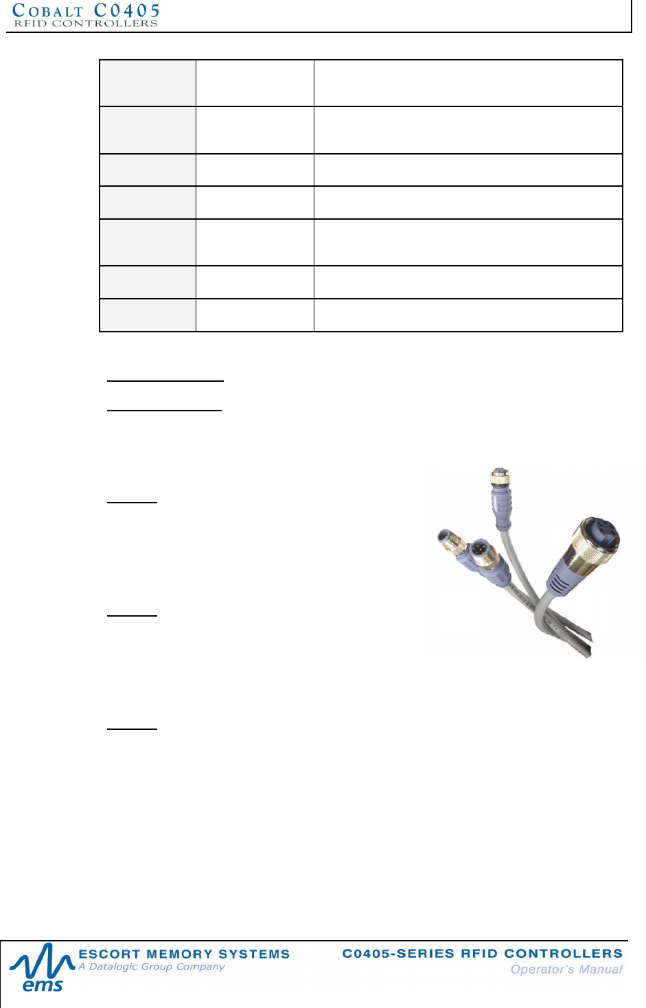
APPENDIX B: MODELS & ACCESSORIES
P/N: 17-1328 REV 02 (08/07) PAGE 73 OF 83
CBL-1496 Termination
Resistor Plug 5-pin, female M12 (ThinNet)
CBL-1497 Termination
Resistor Plug 5-pin, female 7/8-16 (ThickNet)
CBL-1498-02 Cable 5-pin, male M12 to bare wire leads, 2m (ThinNet)
CBL-1514 Connector 5-pin, straight male, reverse-keyed M12 (for USB)
CBL-1515-05 Cable CAT5E shielded Ethernet to 5-Pin, male, D-Code M12,
5m
CBL-1524 Connector 5-pin, straight female, reverse-keyed M12
CBL-1525 Cable Assembly 5-pin, female, reverse-keyed M12 to USB Type A, 3m
Bulk RS232 Cable Belden Cable P/N: 9941
Bulk RS422 cable Belden Cable P/N: 3109A
Power Supplies
00-1166
45W, 24VDC, 1.88A max, Universal Input (90-
264VAC, 47-63Hz), 5.5x2.5mm plug, positive tip;
requires country specific power cord to mate to
IEC 320 power cord receptacle.
00-1167
100W, 24VDC, 4.17A max, Universal Input (90-
264VAC, 47-63Hz), 5.5x2.5mm plug, positive tip;
requires country specific power cord to mate with
IEC 320 power cord receptacle.
00-1168
120W, 24VDC, 5.0A max, Universal Input (88-132VAC/176-264VAC switch
selectable, 47-63Hz) DIN Rail Mount; AC wire receptacles are spring clamped for
direct wire connection.
Escort Memory Systems RFID Tags
Escort Memory Systems designs and manufactures several lines of RFID tags. LRP,
HMS and T-Series passive read/write RFID tags are specially suited for the C0405-
Series product line.

APPENDIX C: NETWORK DIAGRAMS
P/N: 17-1328 REV 02 (08/07) PAGE 74 OF 83
APPENDIX C:
NETWORK DIAGRAMS
§ Subnet16 Gateway - ThickNet Network Diagram
§ Subnet16 Gateway - ThinNet Network Diagram
§ Subnet16 Hub – Network Diagram
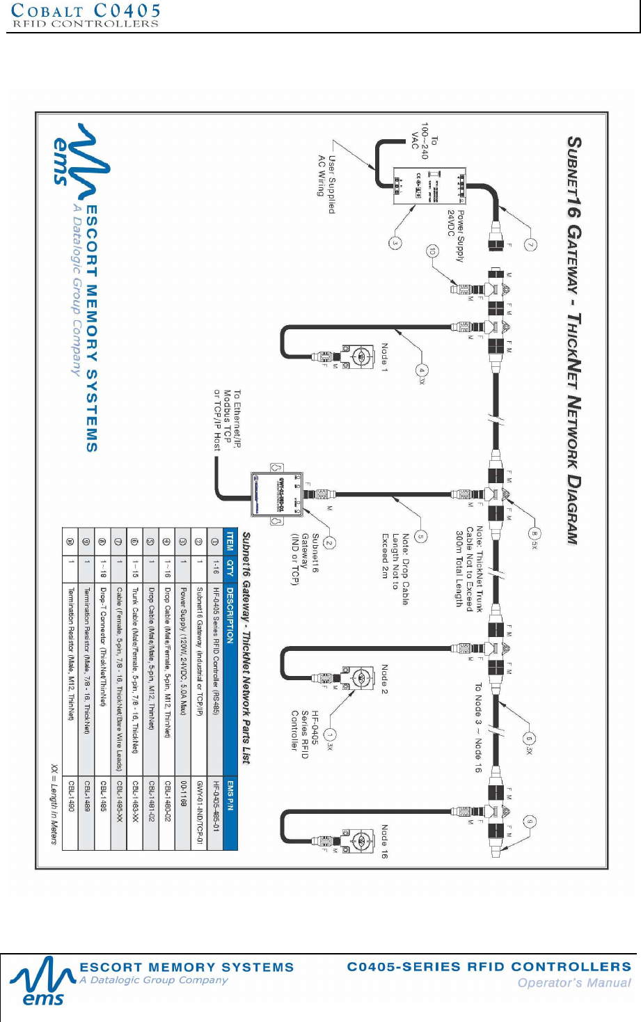
APPENDIX C: NETWORK DIAGRAMS
P/N: 17-1328 REV 02 (08/07) PAGE 75 OF 83
7.6.1 Subnet16 Gateway ThickNet Network Diagram
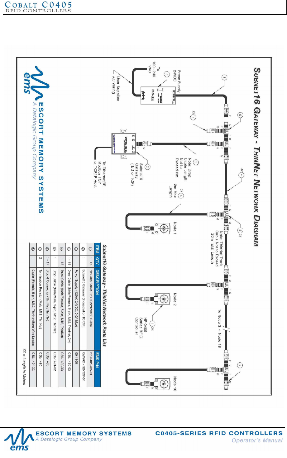
APPENDIX C: NETWORK DIAGRAMS
P/N: 17-1328 REV 02 (08/07) PAGE 76 OF 83
7.6.2 Subnet16 Gateway ThinNet Network Diagram
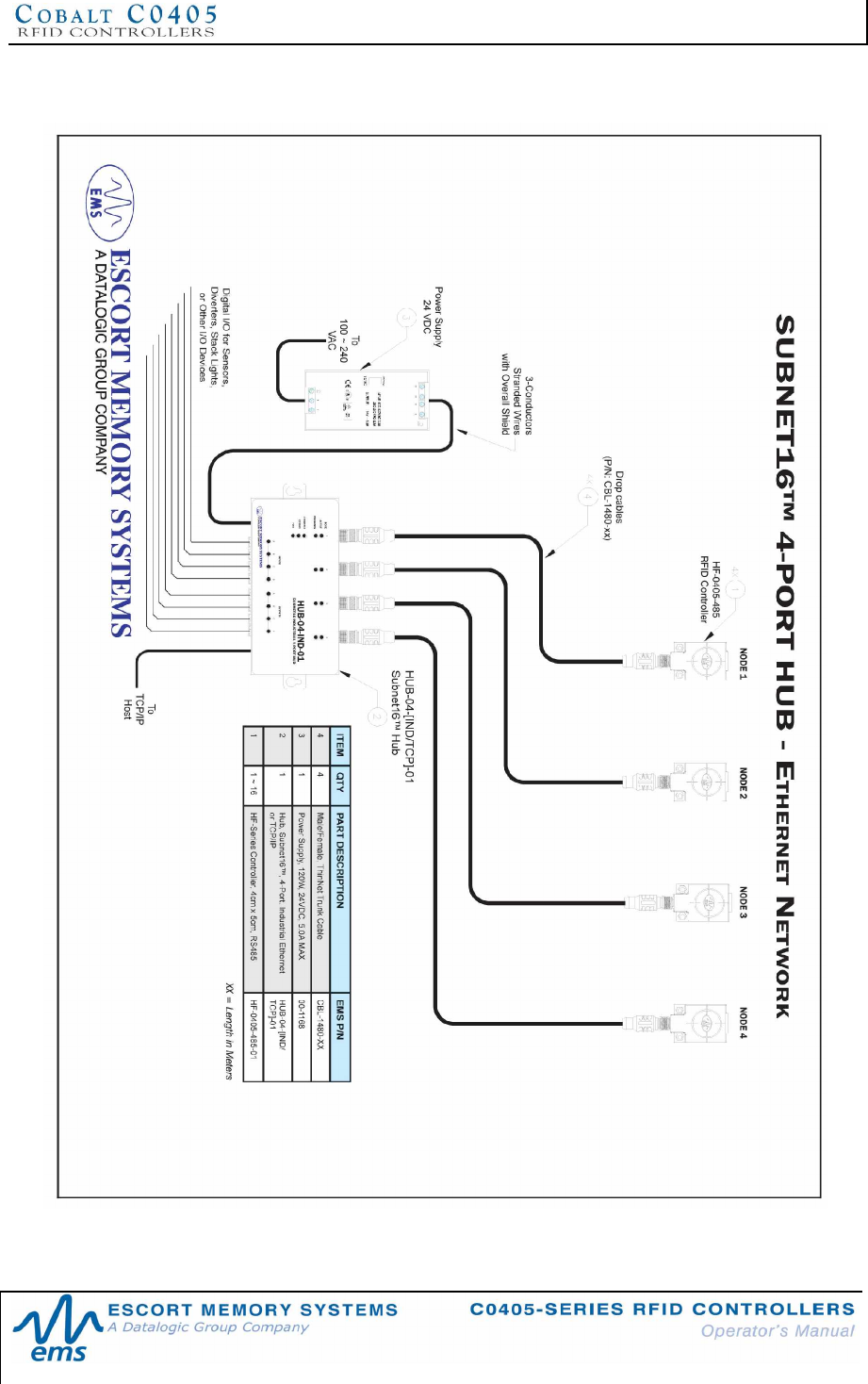
APPENDIX C: NETWORK DIAGRAMS
P/N: 17-1328 REV 02 (08/07) PAGE 77 OF 83
7.6.3 Subnet16 Hub Network Diagram
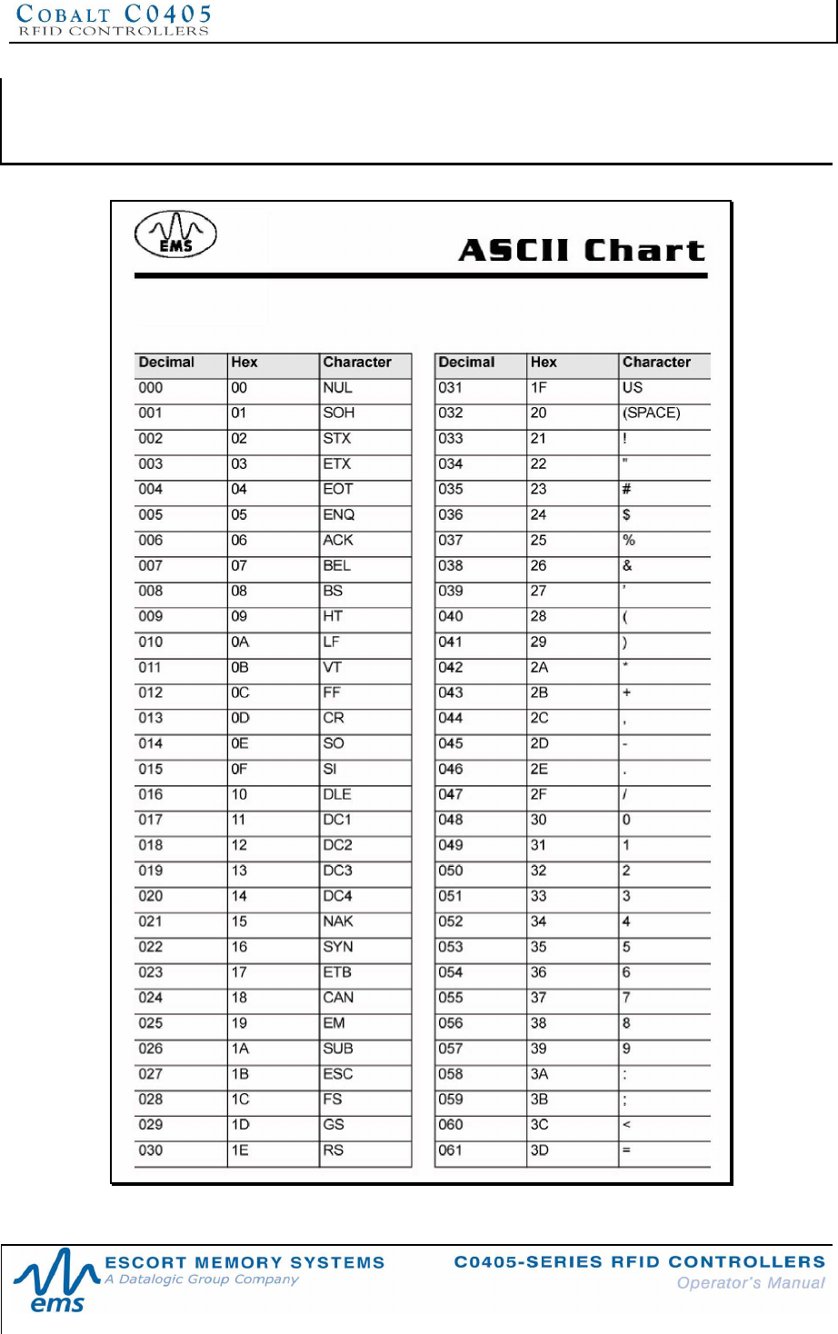
APPENDIX D: ASCII CHART
P/N: 17-1328 REV 02 (08/07) PAGE 78 OF 83
APPENDIX D:
ASCII CHART
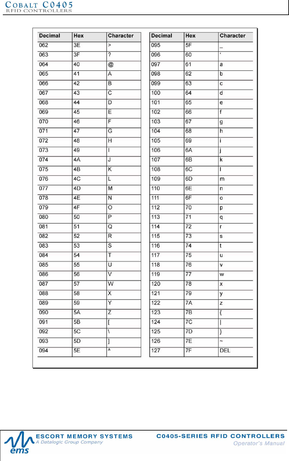
APPENDIX D: ASCII CHART
P/N: 17-1328 REV 02 (08/07) PAGE 79 OF 83
APPENDIX E: RFID TERMINOLOGY
P/N: 17-1328 REV 02 (08/07) PAGE 80 OF 83
APPENDIX E:
RFID TERMINOLOGY
TERM DEFINITION
Antenna The antenna is the part of the RFID controller that radiates RF
energy to, and receives energy from an RFID tag.
ASCII American Standard Code for Information Interchange. A computer
code consisting of 128 alphanumeric and control characters, each
encoded with 7 bits, used for the exchange of information
between computing devices.
ASCII Protocol A protocol used to send ASCII character commands to the
controller. It is possible to use a standard terminal emulator
program to send ASCII commands.
Baud The rate at which a data channel transfers bits of information.
Baud is measured in Bits Per Second (bps).
Binary A numbering system in which numbers are expressed as
combinations of digits 0 and 1, based on powers of 2. In
computing these can be represented electrically as 'on' or 'off'.
Byte Eight bits of data.
Capture
Field/Area/Zone The region of the electromagnetic field, generated by the antenna,
in which transponders will operate. Also called the “RF Field” in
this manual.
Checksum An addition to the contents of a block of data. Data can then be
checked before and after transmission to determine whether any
data has been corrupted or lost.
Continuous Read A mode of operation, in which the controller is instructed to
repeatedly attempt to read any tag within RF range.
EPC Electronic Product Code
Handshaking A mechanism for the regulation of the flow of data between
devices. For example, handshaking can be used to prevent a
controller from temporarily overwhelming the host with Command
Response data.
Hexadecimal (Hex)A method of numerically representing data based on the number
16. Hex notation uses the numbers 0 to 9 and letters A to F
(where the decimal number 10 is represented in hexadecimal as
'A'). In this manual Hex values are preceded by 0x, as in “address
0xFF” (it is also considered correct to append Hex values with a
lower case h, as in interrupt 20h”).
Host The computer or PLC that issues commands to and receives
responses from the RFID controller.
APPENDIX E: RFID TERMINOLOGY
P/N: 17-1328 REV 02 (08/07) PAGE 81 OF 83
TERM DEFINITION
Interface An electrical or physical standard for the interconnection of
devices.
ISM Industry, Science & Medical
LED Light Emitting Diode
LSB Least Significant Byte. Also referred to as the Low Byte or second
byte in a 2-byte “word.”
MSB Most Significant Byte. Also referred to as the High Byte or first
byte in a 2-byte “word.”
Multidrop Multiple devices at various locations connected in parallel (or
acting similar to parallel devices). RS-485 supports Multidrop
RFID controller configurations.
MUX Multiplexer
Noise Unwanted ambient electrical signals found in the operating
environment of RFID equipment.
Orientation The alignment of a transponder with respect to the RFID
controller’s antenna.
Parity A technique used to detect data transmission errors by adding an
extra bit to each character. This bit is set to 1 or 0 to make the
total number of bits ODD or EVEN, depending on the type of
parity in use.
Passive Tags An RFID transponder that does not contain an internal power
source (such as a battery). It is powered by electromagnetic
signals generated from an RFID antenna.
PCB Printed Circuit Board
PLC Programmable Logic Controller (synonymous with Host).
Protocol A set of rules governing the flow of information in a
communications system.
Range (RF) The distance between the antenna and a tag or transponder in an
RFID system at which signals can be properly received.
Read The action of obtaining information contained in a tag.
Reader A device containing digital electronics that can extract information
from a transponder and pass that data on to a host computer.
Read Only A type of RFID tag that has been locked with certain information
written into it (usually during manufacturing) and thereafter can
only be read.
APPENDIX E: RFID TERMINOLOGY
P/N: 17-1328 REV 02 (08/07) PAGE 82 OF 83
TERM DEFINITION
Read/Write A type of RFID tag that allows a controller to retrieve or modify
existing data or write new data to its memory.
Reader/Writer An RFID device that can act as both reader and writer to a tag.
(Synonymous with RFID controller).
Response The string of data sent from the RFID controller to the host after a
command has been issued.
RF Radio Frequency
RFID Radio Frequency Identification
RFID Tag See Transponder
RS232 A common physical interface standard specified by the EIA for the
interconnection of devices. The standard allows for single device
to be connected, point-to-point, at recommended distances up to
15 meters.
RS485 An enhanced version of RS422, which permits multiple devices to
be attached to a twisted pair wire bus at recommended distances
up to 400 meters.
Rx Receive
Tag See Transponder
Transponder An electronic TRANSmitter / resPONDER which is attached to an
object to be identified and, when appropriate RF signals are
received, transmits information as radio signals to an RFID
controller (synonymous with tag).
Tx Transmit
Write The transfer of data to a tag.
Write Length The number of contiguous bytes of tag memory that will be
written.
EMS WARRANTY
P/N: 17-1328 REV 02 (08/07) PAGE 83 OF 83
EMS WARRANTY
scort Memory Systems warrants that all products of its own manufacturing conform to
Escort Memory Systems’ specifications and are free from defects in material and
workmanship when used under normal operating conditions and within the service
conditions for which they were furnished. The obligation of Escort Memory Systems hereunder
shall expire one (1) year after delivery, unless otherwise specified, and is limited to repairing,
or at its option, replacing without charge, any such product that in Escort Memory Systems’
sole opinion proves to be defective within the scope of this Warranty. In the event Escort
Memory Systems is not able to repair or replace defective products or components within a
reasonable time after receipt thereof, Buyers shall be credited for their value at the original
purchase price. Escort Memory Systems must be notified in writing of the defect or
nonconformity within the warranty period and the affected product returned to Escort Memory
Systems factory or to an authorized service center within thirty (30) days after discovery of
such defect or nonconformity. Shipment shall not be made without prior authorization by Escort
Memory Systems.
This is Escort Memory Systems' sole warranty with respect to the products delivered
hereunder. No statement, representation, agreement or understanding oral or written, made by
an agent, distributor, representative, or employee of Escort Memory Systems which is not
contained in this warranty, will be binding upon Escort Memory Systems, unless made in
writing and executed by an authorized Escort Memory Systems employee.
Escort Memory Systems makes no other warranty of any kind what so ever, expressed or
implied, and all implied warranties of merchantability and fitness for a particular use which
exceed the aforementioned obligation are here by disclaimed by Escort Memory Systems and
excluded from this agreement. Under no circumstances shall Escort Memory Systems be liable
to Buyer, in contract or in tort, for any special, indirect, incidental, or consequential damages,
expenses, losses or delay however caused. Equipment or parts that have been subjected to
abuse, misuse, accident, alteration, neglect, unauthorized repair or installation are not covered
by warranty. Escort Memory Systems shall make the final determination as to the existence
and cause of any alleged defect. No liability is assumed for expendable items such as lamps
and fuses. No warranty is made with respect to equipment or products produced to Buyer’s
specification except as specifically stated in writing by Escort Memory Systems in the contract
for such custom equipment. This warranty is the only warranty made by Escort Memory
Systems with respect to the goods delivered hereunder, and may be modified or amended only
by a written instrument signed by a duly authorized officer of Escort Memory Systems and
accepted by the Buyer.
Extended warranties of up to four years are available for purchase for most Escort Memory
Systems products. Contact Escort Memory Systems or your distributor for more information.
COPYRIGHT © 2007 ESCORT MEMORY SYSTEMS, ALL RIGHTS RESERVED
E