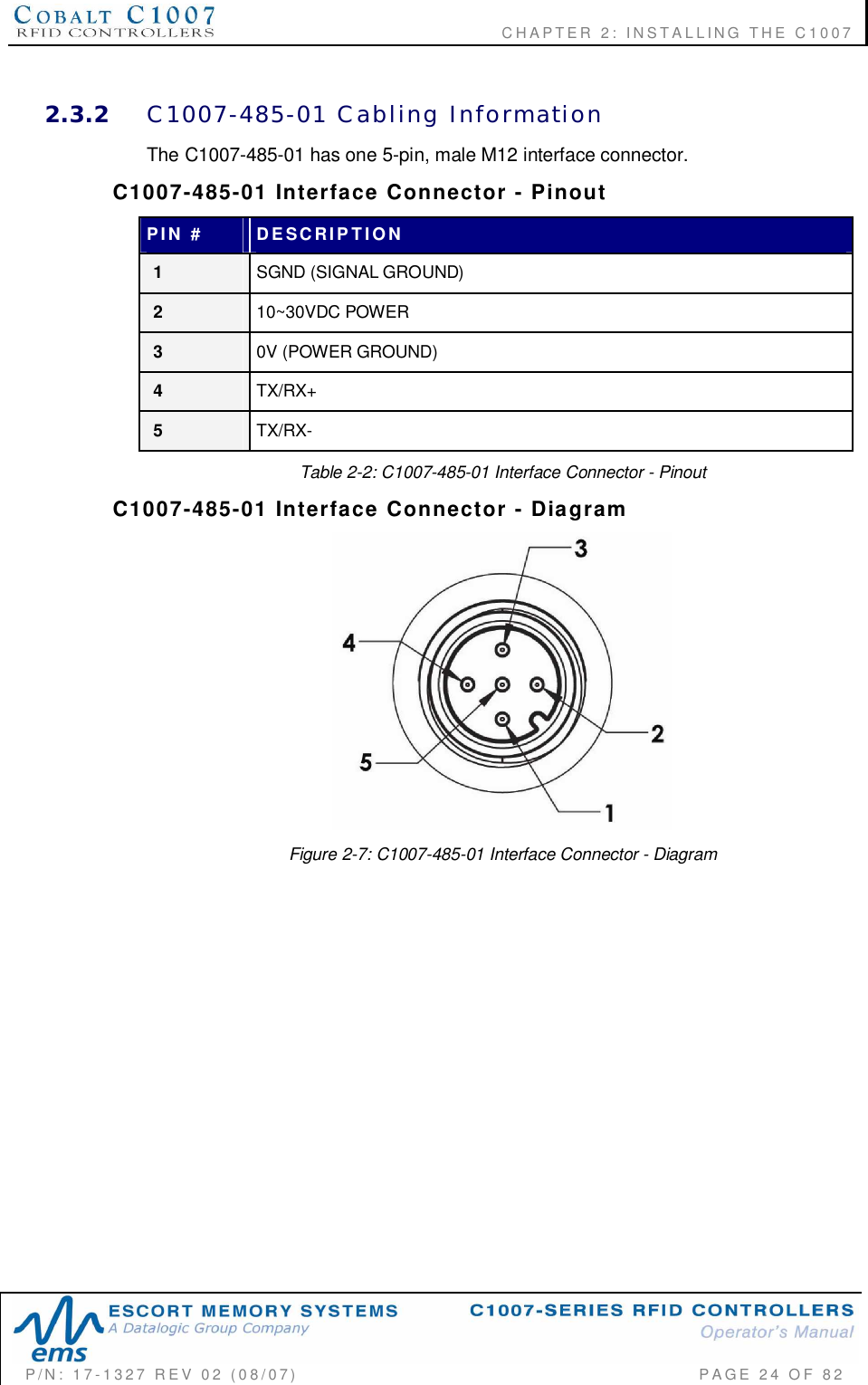
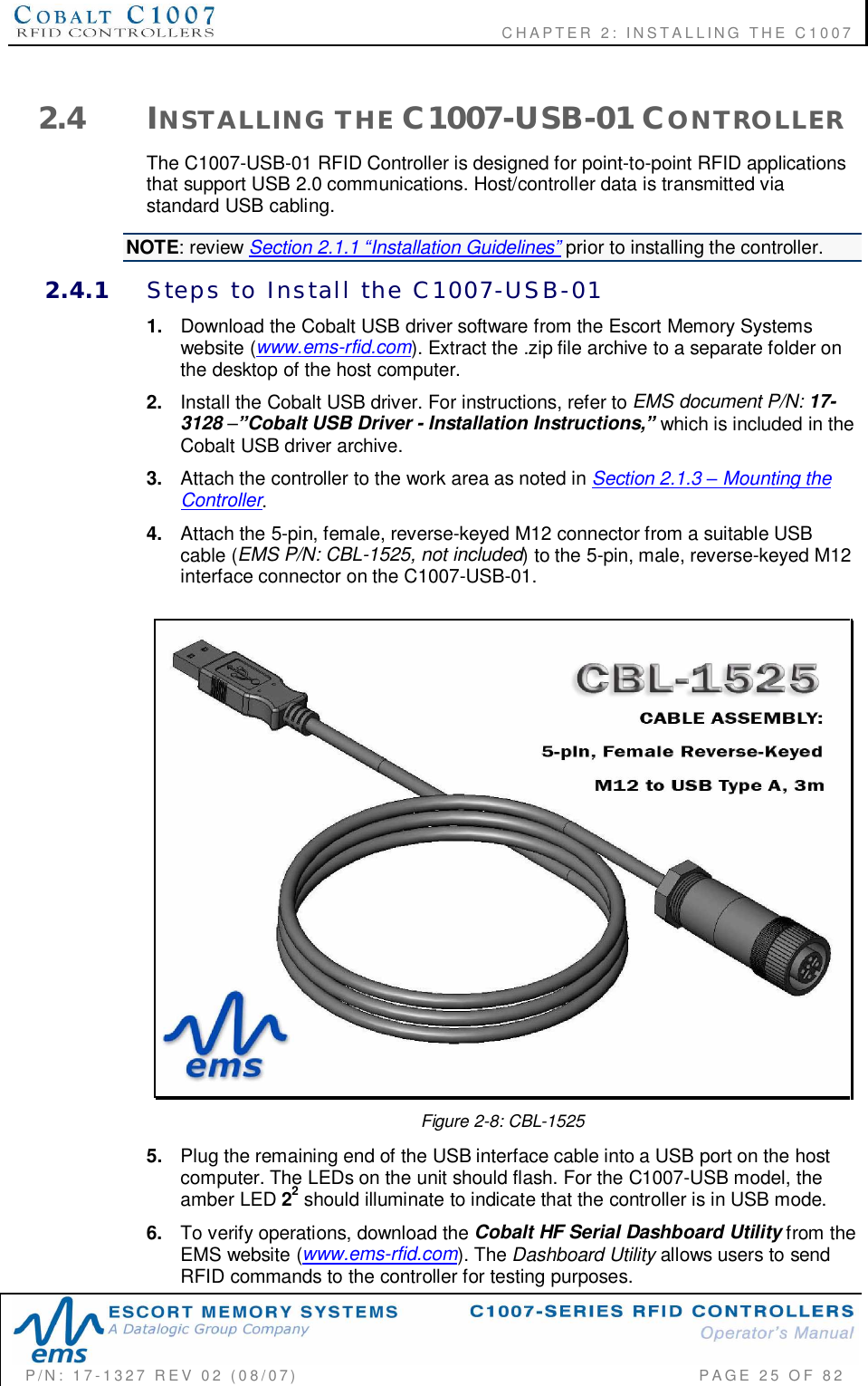
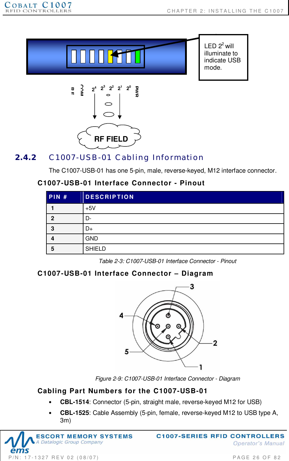
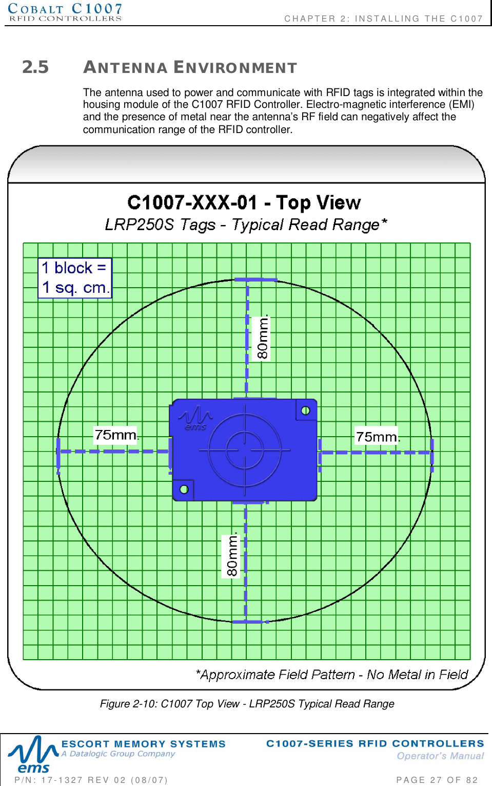
Balluff C1007 Cobalt HF RFID Reader User Manual C1007 Operator s Manual
BALLUFF inc Cobalt HF RFID Reader C1007 Operator s Manual
UserManual.wiki
>
Balluff
>
C1007 User Manual
User Manual
Navigation menu
Upload a User Manual
Namespaces
Wiki Guide
HTML
PDF
Info
Views
User Manual
Discussion / Help
Navigation
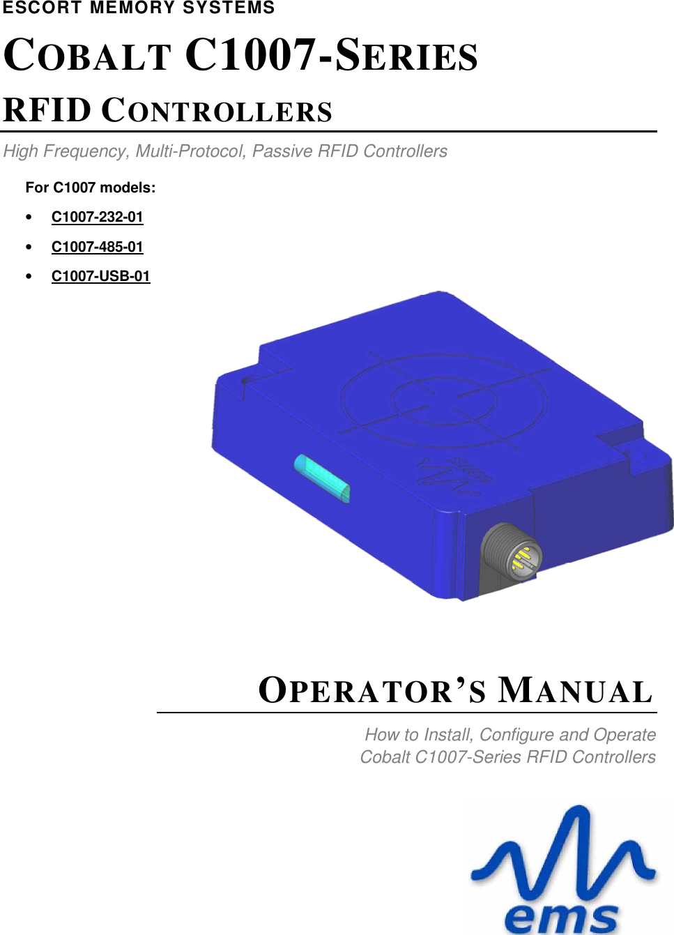
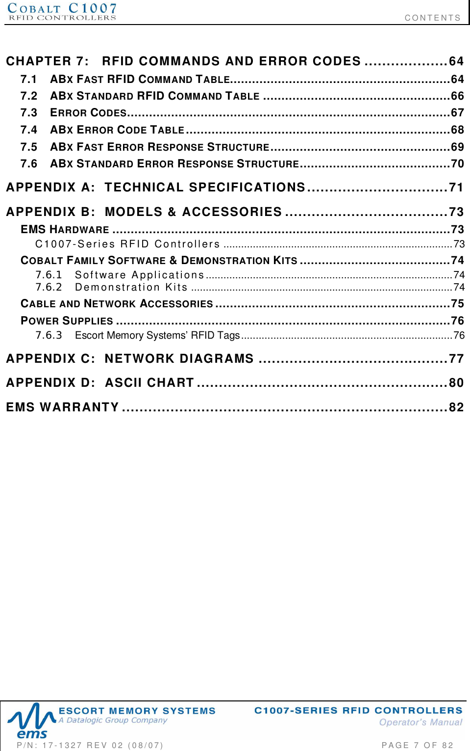
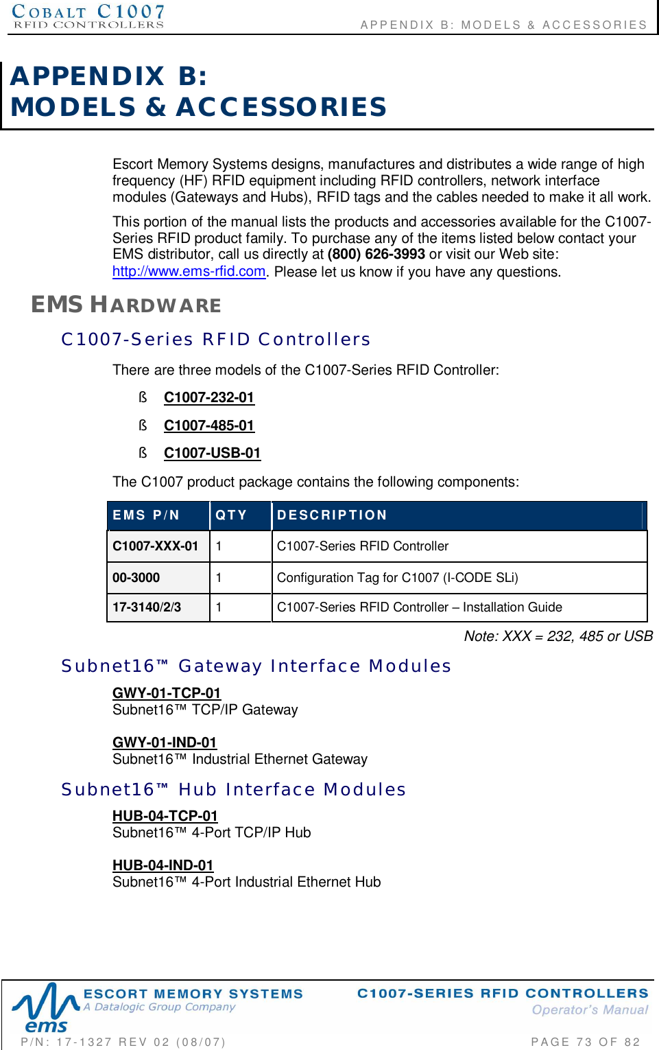
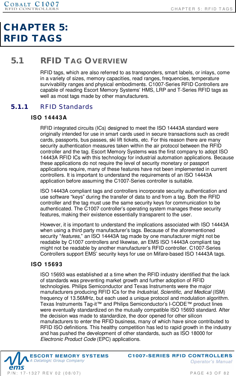
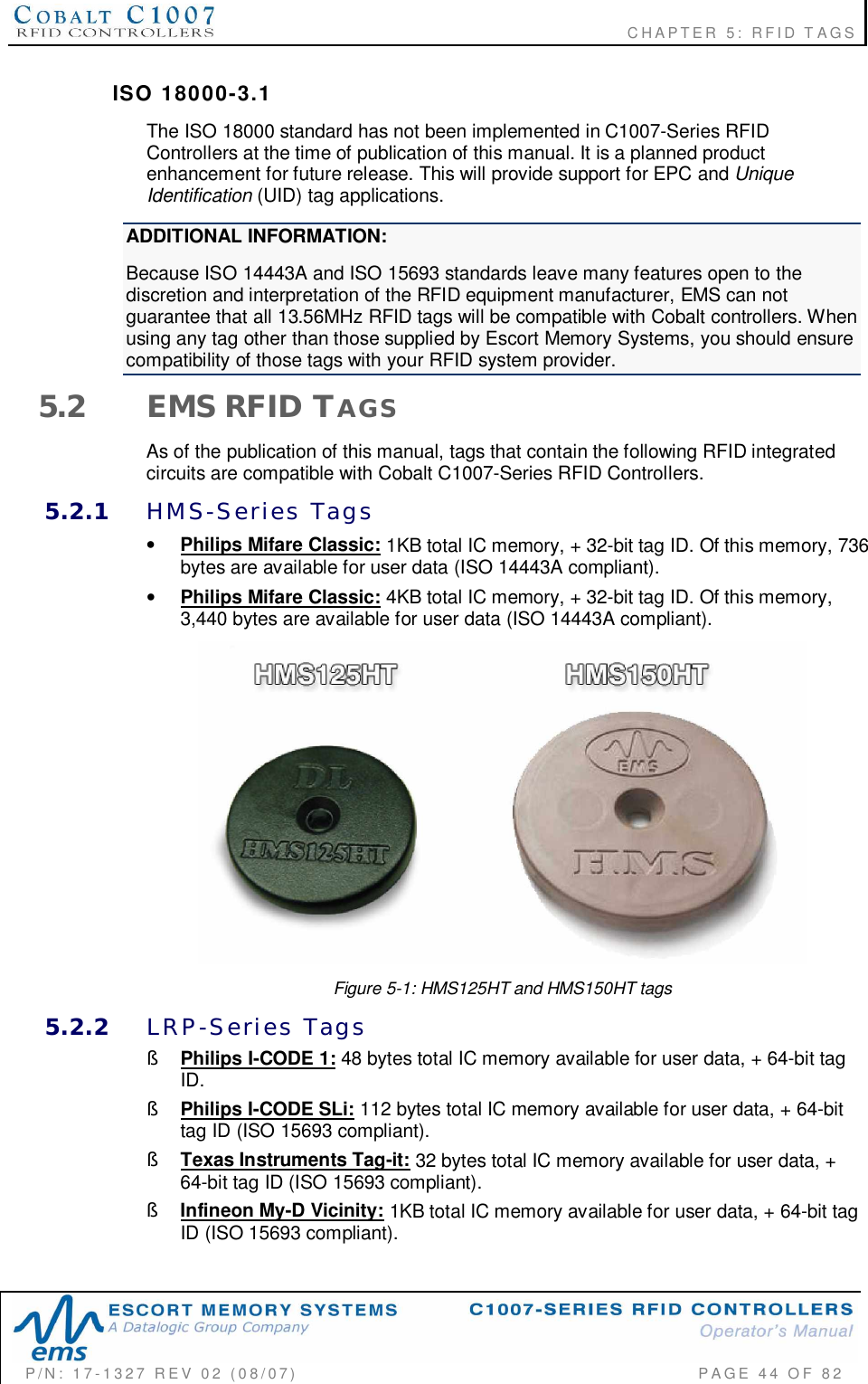
![CHAPTER 2: INSTALLING THE C1007P/N: 17-1327 REV 02 (08/07) PAGE 16 OF 822.1.2 C1007 Controller DimensionsThe graphic below contains the dimensions of the Cobalt C1007-Series RFIDControllers. Dimensions are listed in millimeters and [inches].Figure 2-1: C1007 RFID Controller DimensionsTightenmountingscrews tobetween 1.3and 1.7 Nm (12 15 lbf/in).](https://usermanual.wiki/Balluff/C1007/User-Guide-828605-Page-16.png)
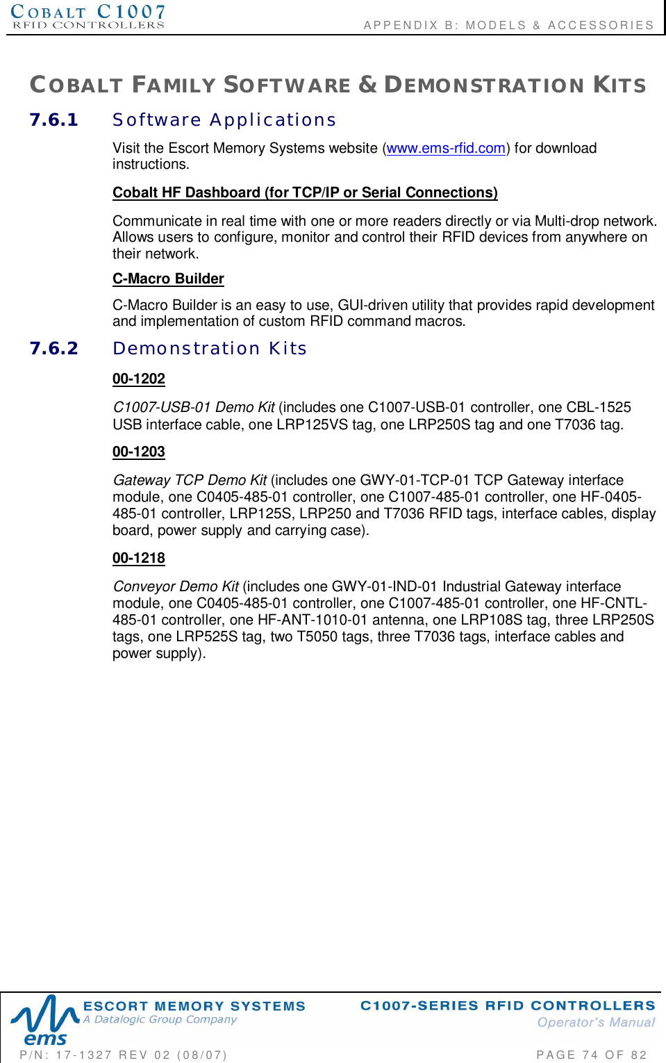
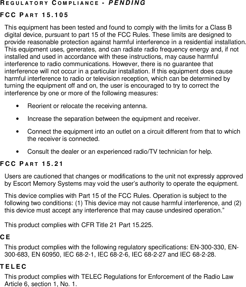
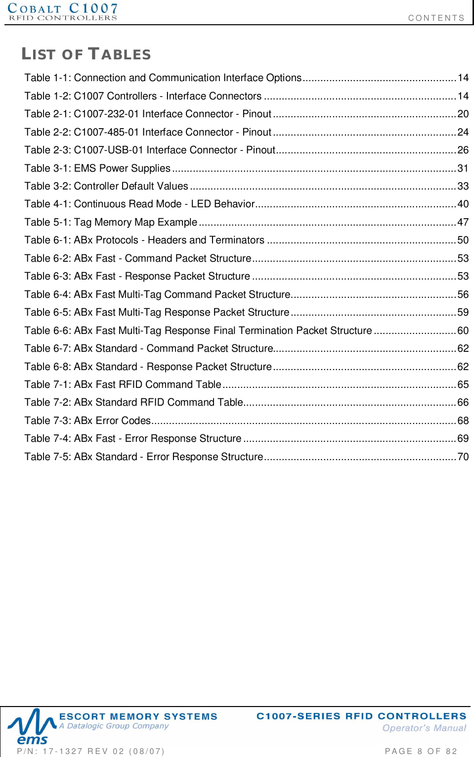
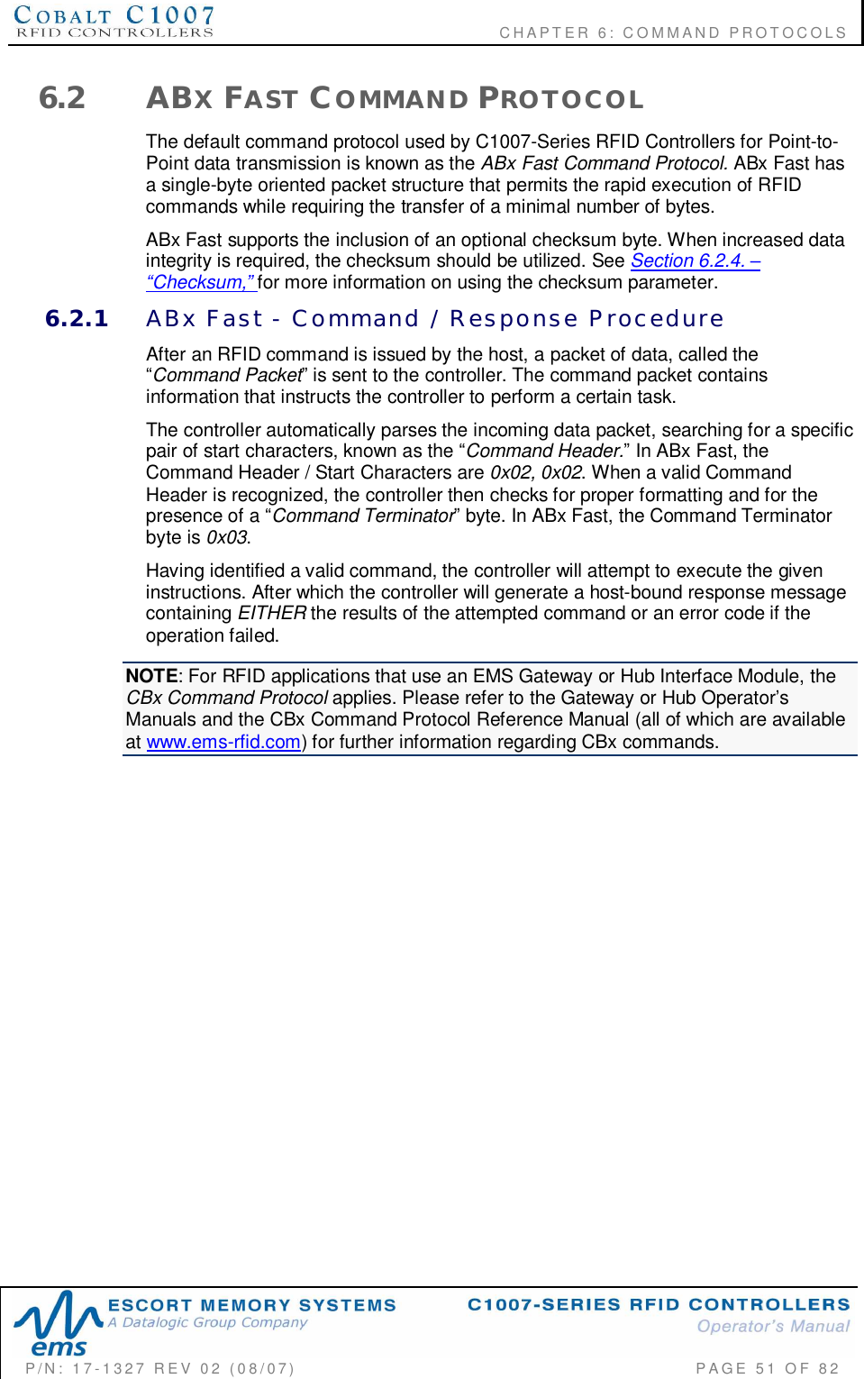
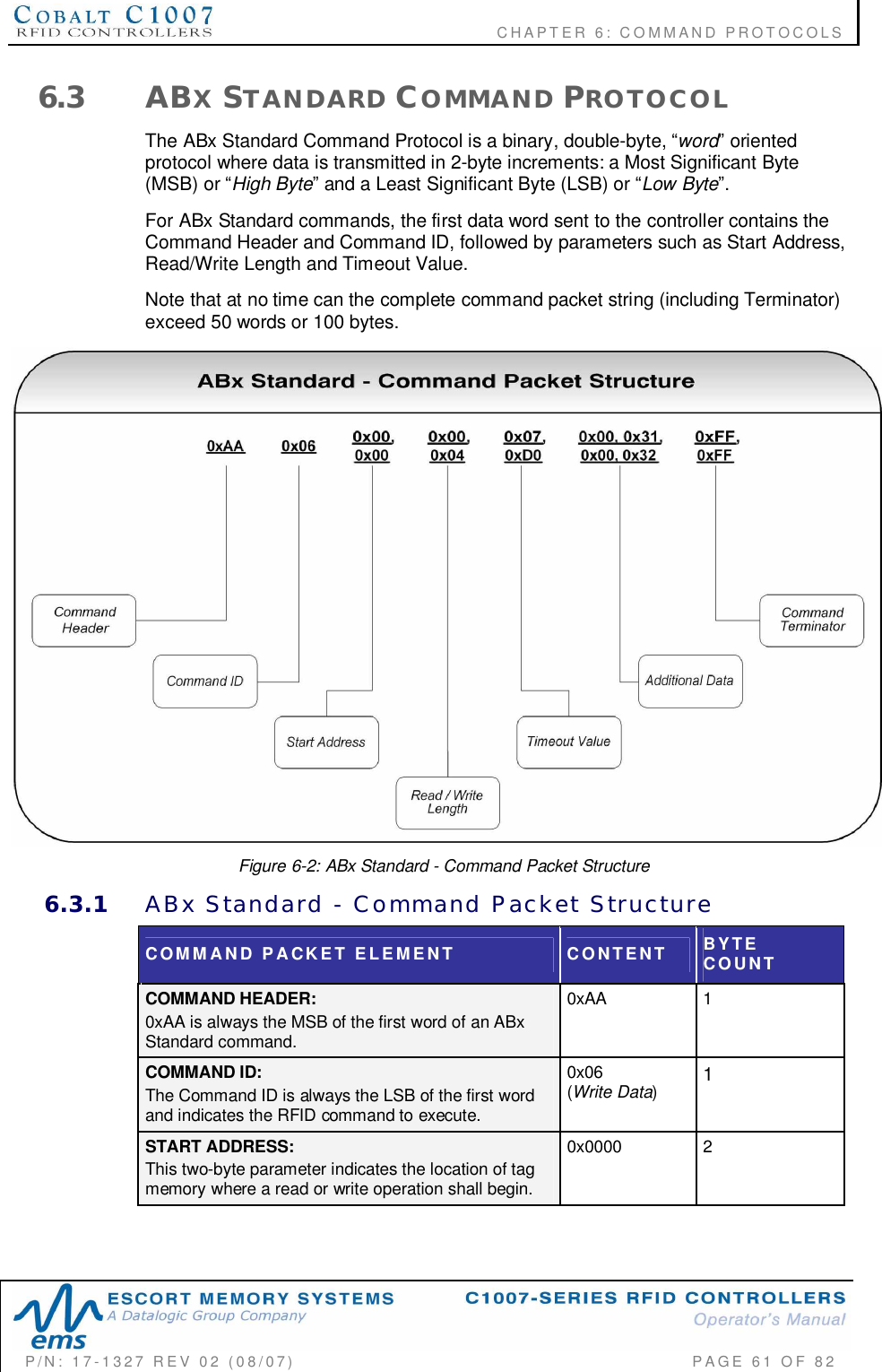
![CHAPTER 6: COMMAND PROTOCOLSP/N: 17-1327 REV 02 (08/07) PAGE 50 OF 826.1.1 ABx Protocols - Command StructuresAll ABx-based RFID commands contain certain fundamental packet elements,including a Command Header, a Command ID, one or more CommandParameters (when applicable) and a Command Terminator.Command Packet Structure = [Command Header + Command ID + Command Parameters+ Command Terminator]6.1.2 ABx Protocols - Headers and TerminatorsIn ABx Fast, commands begin with the two-byte command header 0x02, 0x02 andend with the one-byte command terminator 0x03.In ABx Standard, commands begin with the one-byte command header "0xAA," andend with the two-byte command terminator "0xFF, 0xFF".ABx Protocols - Headers and TerminatorsABX PROTOCOL HEADER TERMINATORABx Fast 0x02, 0x02 0x03ABx Standard 0xAA 0xFF, 0xFFTable 6-1: ABx Protocols - Headers and Terminators6.1.3 ABx Protocols - Response StructuresAfter completing an ABx command, the C1007 generates a host-bound, responsepacket that indicates the status and/or results of the attempted command. Theresponse packet structure for all ABx protocols consists of a Response Header, aCommand Echo, one or more Response Values (when applicable), and aResponse Terminator.Response Packet Structure = [Response Header + Command Echo + Response Values +Response Terminator]Note that for each ABx protocol, Response Header and Response Terminatorparameters are the same as their Command Header and Command Terminatorcounterparts.](https://usermanual.wiki/Balluff/C1007/User-Guide-828605-Page-50.png)
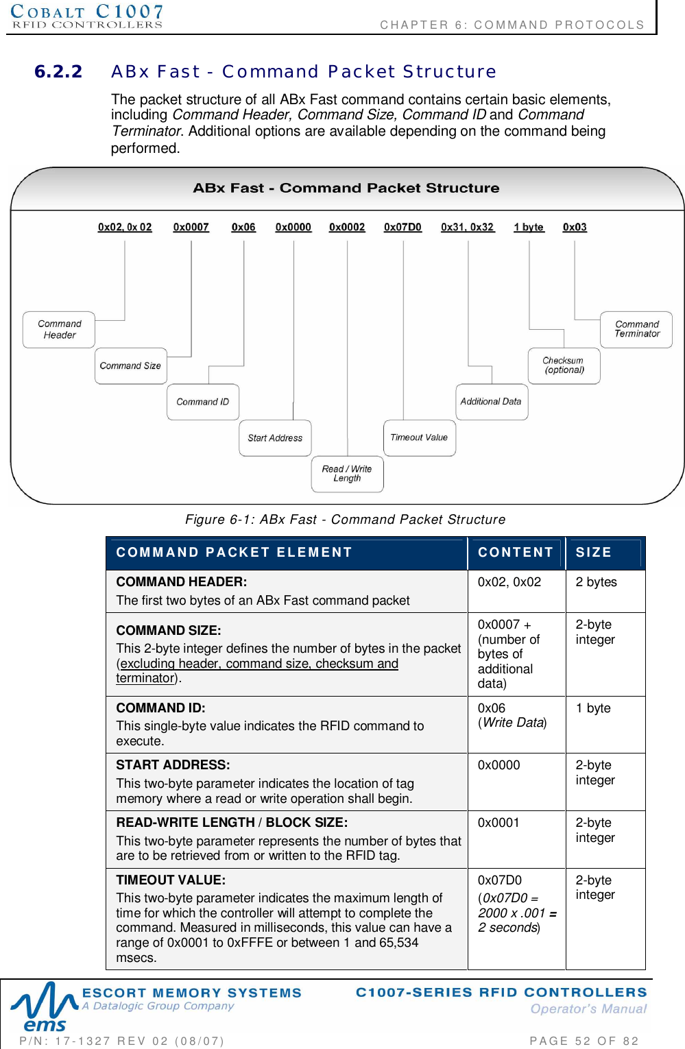
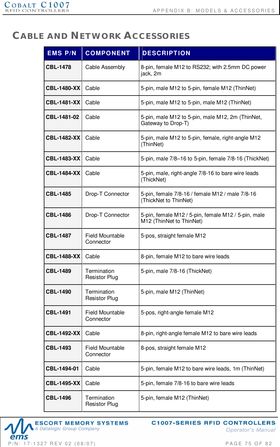
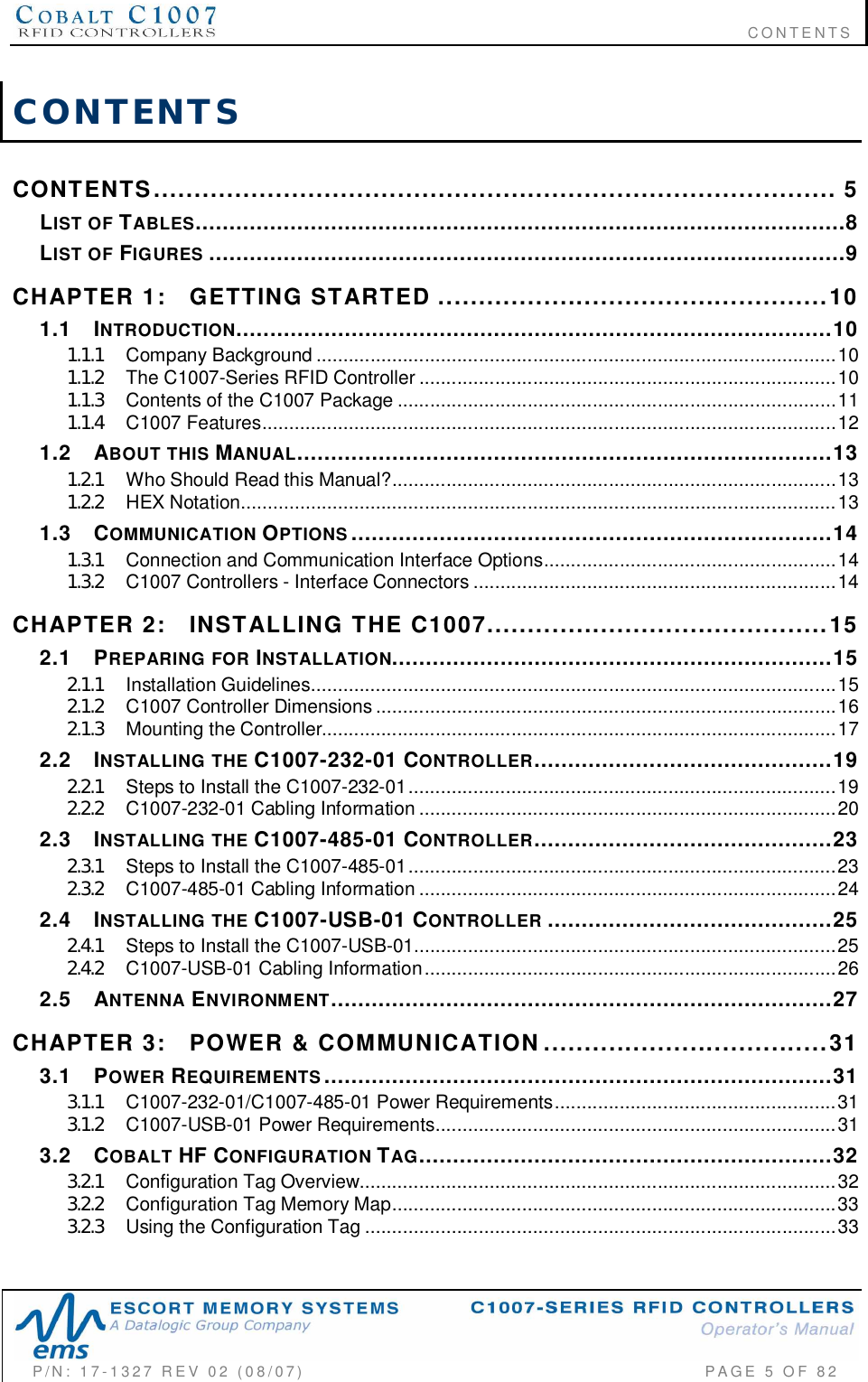
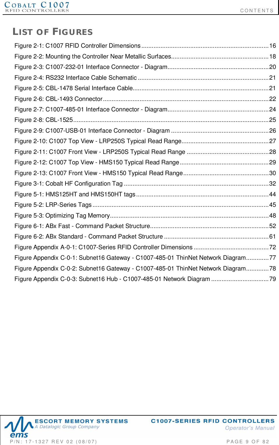
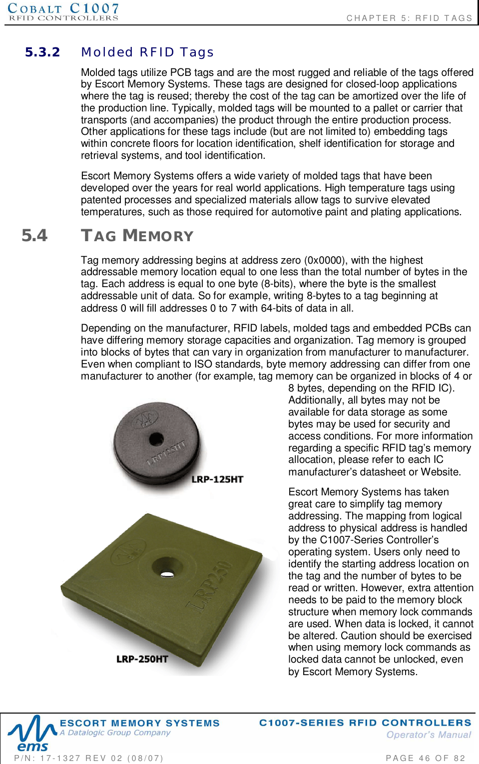
![CHAPTER 6: COMMAND PROTOCOLSP/N: 17-1327 REV 02 (08/07) PAGE 55 OF 82ChecksumABx Fast and ABx ASCII Command Protocols support the inclusion of an additionalChecksum byte that is used to verify the integrity of data being transmitted betweenhost and controller.The Checksum is calculated by adding together (summing) the byte values in thecommand packet (less the Header, Checksum and Terminator), and then subtractingthe total byte sum from 0xFF. Therefore, when the byte values of each packetelement (from Command Size to Checksum) are added together, the byte value sumwill equal 0xFF.CHECKSUM EXAMPLEThe following example depicts Command 0x05 (Read Data) using a Checksum (StartAddress: 0x0001, Read Length: 0x0004, Timeout Value: 0x07D0).COMMANDPACKETELEMENTCONTENTS USED IN CHECKSUMCommand Header 0x02, 0x02 n/aCommand Size 0x0007 0x00, 0x07Command ID 0x05 0x05Start Address 0x0001 0x00, 0x01Read Length 0x0004 0x00, 0x04Timeout Value 0x07D0 0x07, 0xD0Checksum 0x17 n/aCommand Terminator 0x03 n/aAdd the byte values from the Command Size, Command ID, Start Address, ReadLength and Timeout Value parameters together and subtract from 0xFF. Resultingvalue will be the Checksum.[0x07 + 0x05 + 0x01 + 0x04 + 0x07 + 0xD0] = 0xE8The Checksum equation is: [0xFF 0xE8] = 0x176.2.5 ABx Fast Multi-Tag Command Packet StructureABx Fast Multi-tag Commands are capable of interrogating one or more RFID tags,when numerous tags are simultaneously within RF range. These commands alsoChecksum =[0xFF (sumof thesefields)]](https://usermanual.wiki/Balluff/C1007/User-Guide-828605-Page-55.png)
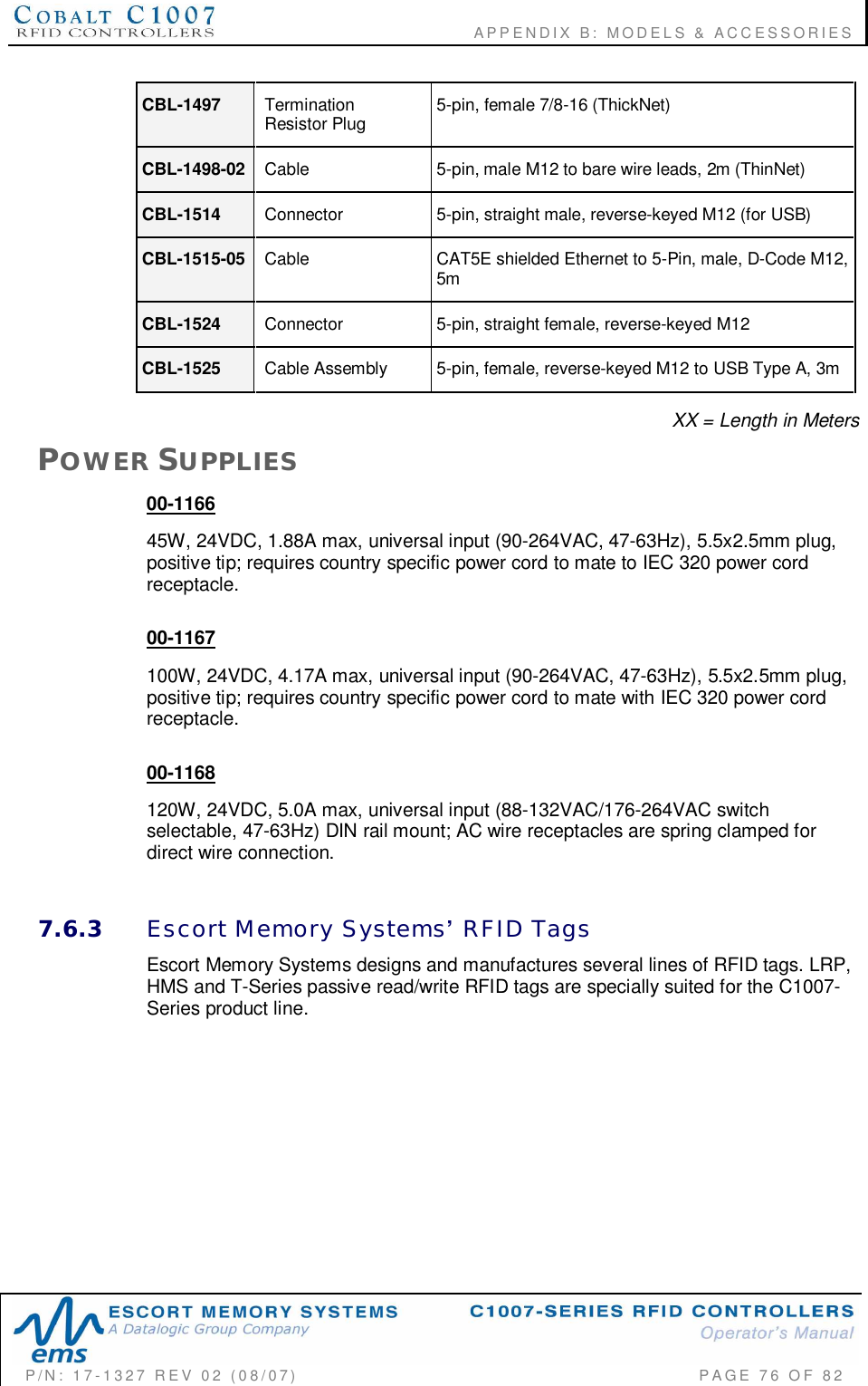
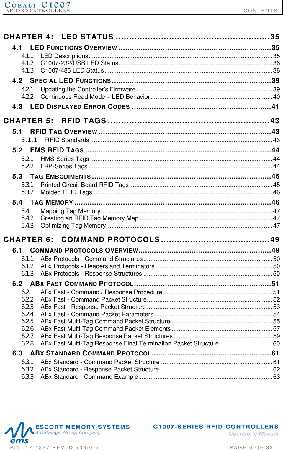
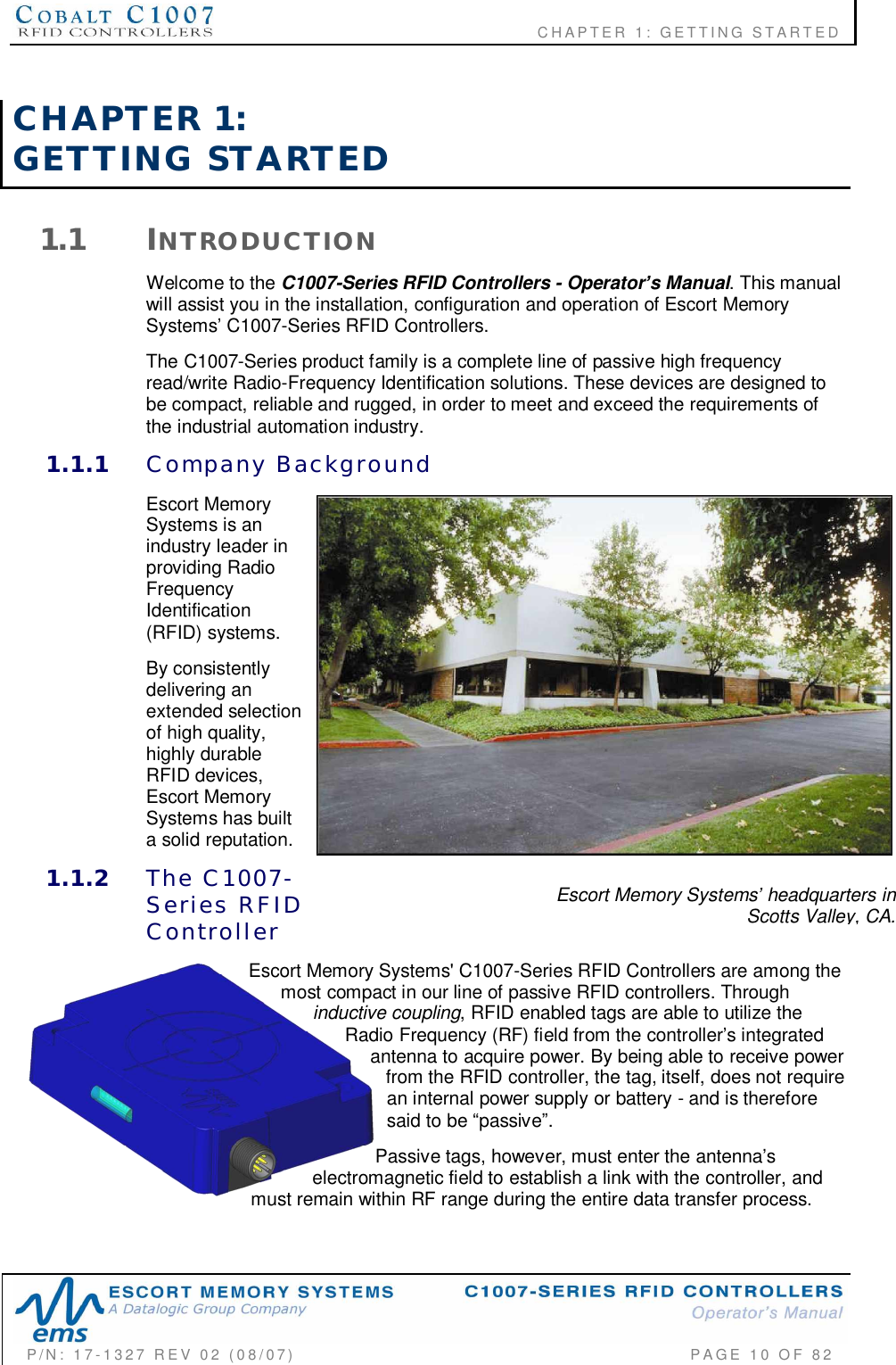
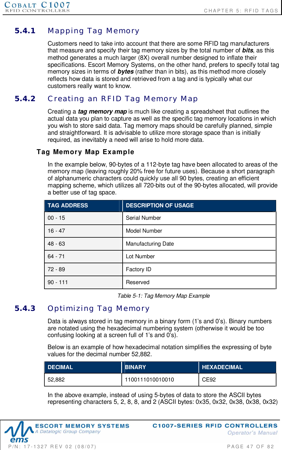
![APPENDIX A: TECHNICAL SPECIFICATIONSP/N: 17-1327 REV 02 (08/07) PAGE 72 OF 82C1007-SERIES RFID CONTROLLER DIMENSIONSDimensions are listed in millimeters and [inches].Figure Appendix A-0-1: C1007-Series RFID Controller Dimensions](https://usermanual.wiki/Balluff/C1007/User-Guide-828605-Page-72.png)