Balluff CHS1265 Active RFID Reader Writer User Manual 17 1339 REV02 CHS1265 TCP 01 Operators Manual
BALLUFF inc Active RFID Reader Writer 17 1339 REV02 CHS1265 TCP 01 Operators Manual
UserManual.wiki
>
Balluff
>
CHS1265 User Manual
User Manual
Navigation menu
Upload a User Manual
Namespaces
Wiki Guide
HTML
PDF
Info
Views
User Manual
Discussion / Help
Navigation

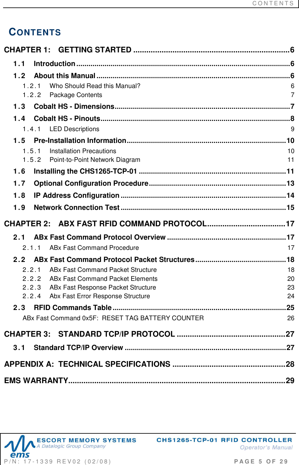
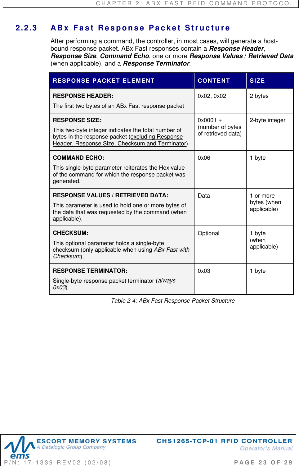
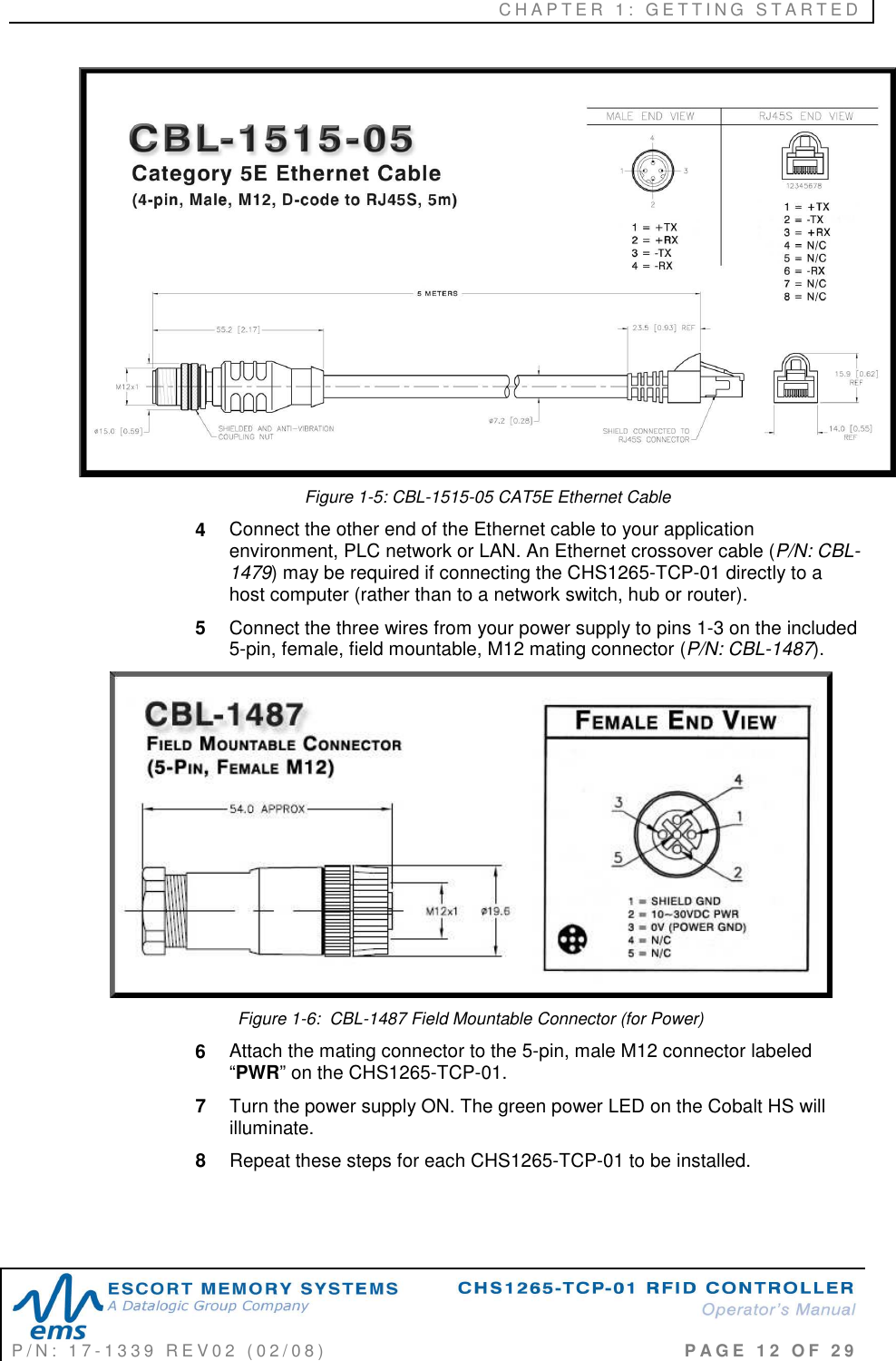
![C H A P T E R 1 : G E T T I N G S T A R T E D P / N : 1 7 - 1 3 3 9 R E V 0 2 ( 0 2 / 0 8 ) P A G E 1 1 O F 2 9 1.5.2 P o i n t - t o -P o i n t N e t w o r k D i a g r a m Figure 1-4: Cobalt HS - Point-to-Point Network Diagram 1.6 INSTALLING THE CHS1265-TCP-01 1 Unpack and inspect the CHS1265-TCP-01 hardware and accessories. If an item appears to be damaged, notify your EMS distributor immediately. 2 Securely mount the CHS1265-TCP-01 to your chosen location using four (4) #10 [M5] screws and matching locking washers and nuts (not included). The CHS1265-TCP-01 must be mounted so that the unit’s antenna is properly oriented along the path your RFID tags will travel. The Cobalt HS should also be aligned in such a manner that the LED indicators can be seen during normal operation. 3 Attach the 4-pin, male M12 end of a compatible Category 5E Ethernet cable (EMS P/N: CBL-1515-05) to the connector labeled “ETHERNET” on the Cobalt HS.](https://usermanual.wiki/Balluff/CHS1265/User-Guide-977853-Page-11.png)
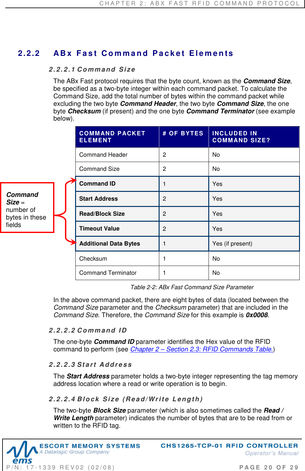
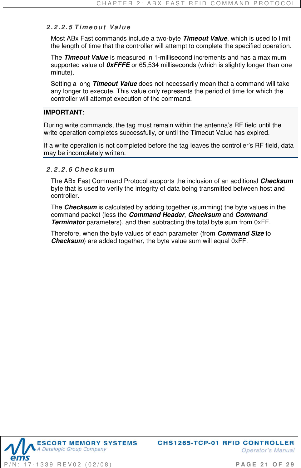
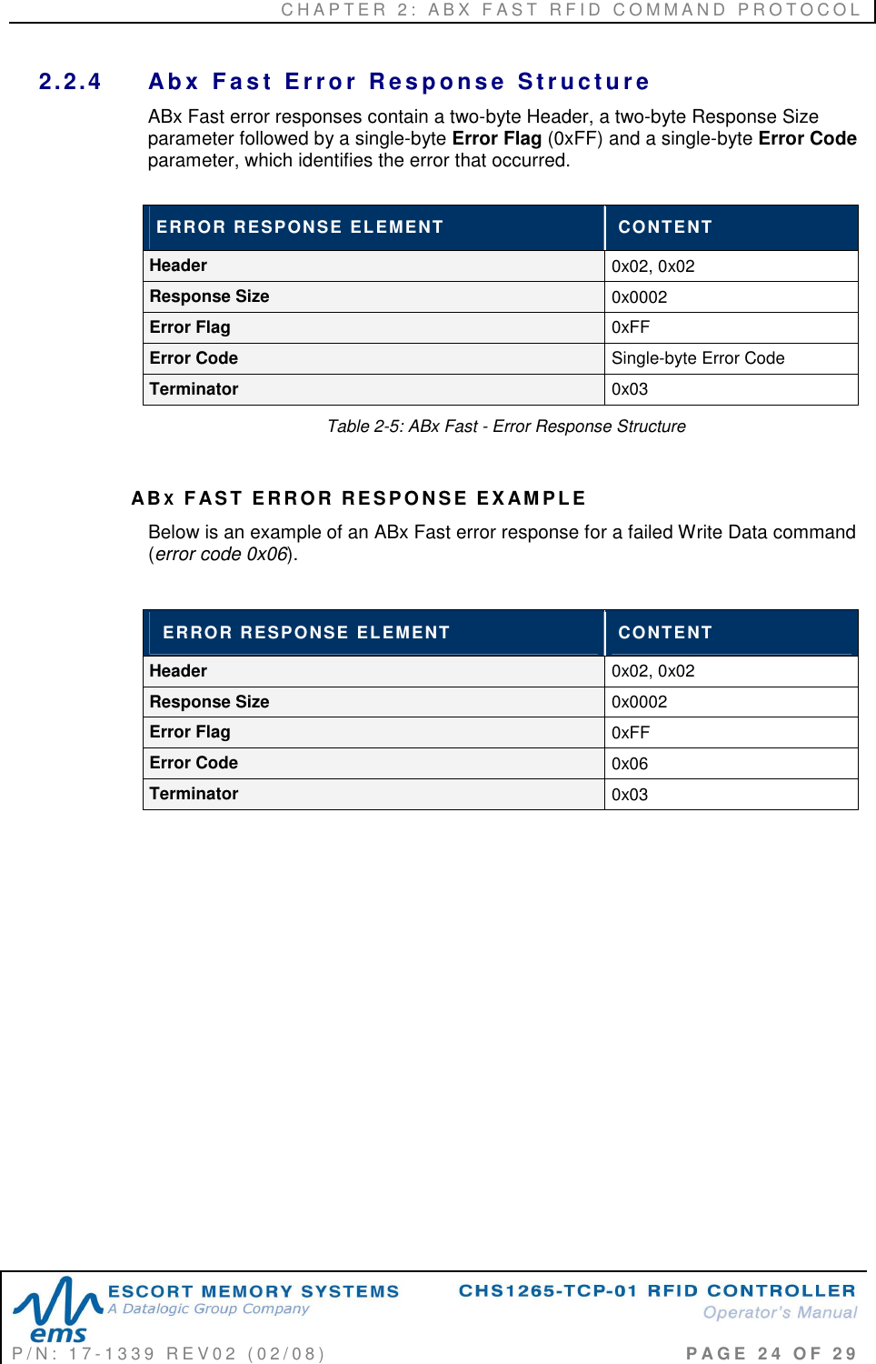
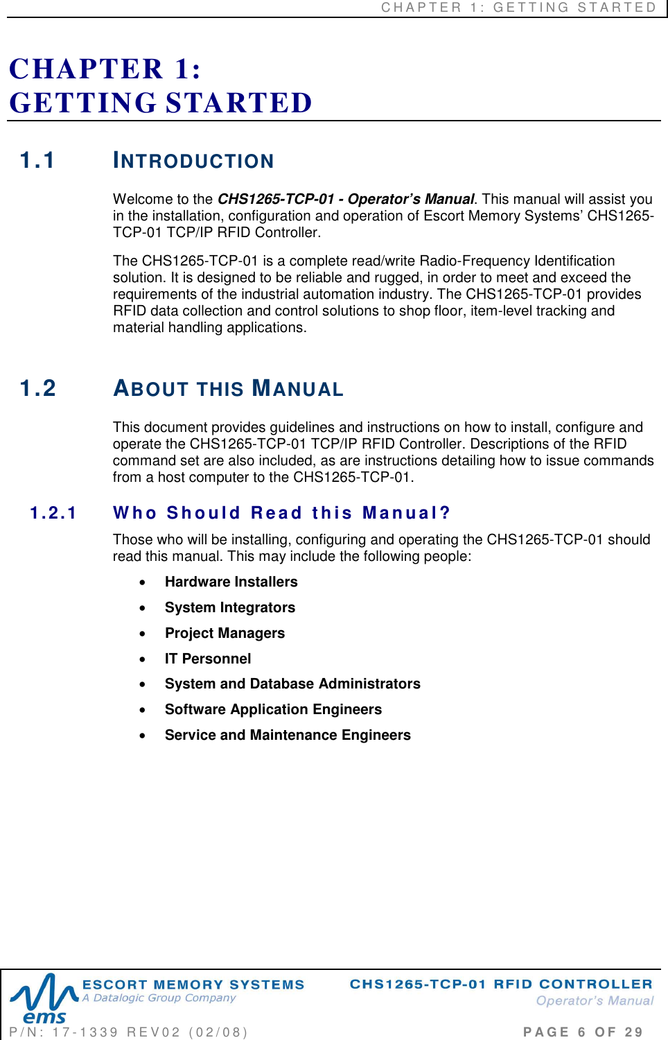
![C H A P T E R 2 : A B X F A S T R F I D C O M M A N D P R O T O C O L P / N : 1 7 - 1 3 3 9 R E V 0 2 ( 0 2 / 0 8 ) P A G E 2 2 O F 2 9 CH E C K S U M EX A M P L E The following example depicts Command 0x05 (Read Data) when using a Checksum. COMMAND ELEMENT CONTENTS USED IN CHECKSUM Header 0x02, 0x02 n/a Command Size 0x0007 0x00, 0x07 Command ID 0x05 0x05 Start Address 0x0001 0x00, 0x01 Block Size 0x0004 0x00, 0x04 Timeout Value 0x07D0 0x07, 0xD0 Checksum 0 x 1 7 n/a Terminator 0x03 n/a Table 2-3: ABx Fast - Checksum Example Add the byte values from the Command Size, Command ID, Start Address, Block Size and Timeout Value parameters together and subtract from 0xFF. The resulting value will be the Checksum. [ 0 x 0 7 + 0 x 0 5 + 0 x 0 1 + 0 x 0 4 + 0 x 0 7 + 0 x D 0 ] = 0 x E 8 The checksum equation is: [0xFF – 0xE8] = 0 x 1 7 Checksum = [0xFF – (sum of these fields)]](https://usermanual.wiki/Balluff/CHS1265/User-Guide-977853-Page-22.png)