Balluff CHS1265 Active RFID Reader Writer User Manual 17 1339 REV02 CHS1265 TCP 01 Operators Manual
BALLUFF inc Active RFID Reader Writer 17 1339 REV02 CHS1265 TCP 01 Operators Manual
Balluff >
User Manual

ESCORT MEMORY SYSTEMS
CHS1265
CHS1265CHS1265
CHS1265-
--
-TCP
TCPTCP
TCP-
--
-01
0101
01
TCP/IP RFID Controller
Operator’s Manual
P/N: 17-1339 REV 02 (02/08)
Escort Memory Systems reserves the right to make modifications or improvements to
its products and/or documentation without prior notification. Escort Memory Systems
shall not be liable for technical or editorial errors or omissions contained herein, nor
for incidental or consequential damages resulting from the use of this material.
Product names mentioned herein are for identification purposes only and may be
trademarks and/or registered trademarks of their respective companies.
EMS®, Escort Memory Systems® and the Escort Memory Systems logo are
registered trademarks of Escort Memory Systems, a Datalogic Group Company.
COPYRIGHT © 20 07 ESCORT MEMO RY SYSTEMS, ALL RIGHTS RESERVED
E
SC O RT
M
EM OR Y
S
Y S T E M S
CHS1265-TCP-01
T C P/ IP R FID C on t ro ll e r
O
PERATOR’S
M
ANUAL
How to Install, Configure and Operate
Escort Memory Systems’
CHS1265-TCP-01 TCP/IP RFID Controller
R
EGULATORY
C
OMPLIANCE
FCC Part 15
This equipment has been tested and found to comply with the limits for a Class A
digital device, pursuant to part 15 of the FCC Rules. These limits are designed to
provide reasonable protection against harmful interference in a residential installation.
This equipment uses, generates, and can radiate radio frequency energy and, if not
installed and used in accordance with these instructions, may cause harmful
interference to radio communications. However, there is no guarantee that
interference will not occur in a particular installation. If this equipment does cause
harmful interference to radio or television reception, which can be determined by
turning the equipment off and on, the user is encouraged to try to correct the
interference by one or more of the following measures:
Reorient or relocate the receiving antenna.
Increase the separation between the equipment and receiver.
Connect the equipment into an outlet on a circuit different from that to which
the receiver is connected.
Consult the dealer or an experienced radio/TV technician for help.
Users are cautioned that changes or modifications to the unit not expressly approved
by Escort Memory Systems may void the user’s authority to operate the equipment.
This device complies with Part 15 of the FCC Rules. Operation is subject to the
following two conditions: (1) this device may not cause harmful interference, and (2)
this device must accept any interference that may cause undesired operation.
This product complies with CFR Title 21 Part 15.

C O N T E N T S
P / N : 1 7 - 1 3 3 9 R E V 0 2 ( 0 2 / 0 8 ) P A G E 5 O F 2 9
C
ONTENTS
CHAPTER 1: GETTING STARTED ........................................................................6
1.1 Introduction..........................................................................................................6
1.2 About this Manual................................................................................................6
1 . 2 . 1
Who Should Read this Manual? 6
1 . 2 . 2
Package Contents 7
1.3 Cobalt HS - Dimensions.......................................................................................7
1.4 Cobalt HS - Pinouts..............................................................................................8
1 . 4 . 1
LED Descriptions 9
1.5 Pre-Installation Information...............................................................................10
1 . 5 . 1
Installation Precautions 10
1 . 5 . 2
Point-to-Point Network Diagram 11
1.6 Installing the CHS1265-TCP-01 .........................................................................11
1.7 Optional Configuration Procedure....................................................................13
1.8 IP Address Configuration..................................................................................14
1.9 Network Connection Test..................................................................................15
CHAPTER 2: ABX FAST RFID COMMAND PROTOCOL....................................17
2.1 ABx Fast Command Protocol Overview ...........................................................17
2 . 1 . 1
ABx Fast Command Procedure 17
2.2 ABx Fast Command Protocol Packet Structures.............................................18
2 . 2 . 1
ABx Fast Command Packet Structure 18
2 . 2 . 2
ABx Fast Command Packet Elements 20
2 . 2 . 3
ABx Fast Response Packet Structure 23
2 . 2 . 4
Abx Fast Error Response Structure 24
2.3 RFID Commands Table......................................................................................25
ABx Fast Command 0x5F: RESET TAG BATTERY COUNTER 26
CHAPTER 3: STANDARD TCP/IP PROTOCOL ..................................................27
3.1 Standard TCP/IP Overview ................................................................................27
APPENDIX A: TECHNICAL SPECIFICATIONS ....................................................28
EMS WARRANTY....................................................................................................29

C H A P T E R 1 : G E T T I N G S T A R T E D
P / N : 1 7 - 1 3 3 9 R E V 0 2 ( 0 2 / 0 8 ) P A G E 6 O F 2 9
CHAPTER 1:
GETTING
STARTED
1.1 I
NTRODUCTION
Welcome to the CHS1265-TCP-01 - Operator’s Manual. This manual will assist you
in the installation, configuration and operation of Escort Memory Systems’ CHS1265-
TCP-01 TCP/IP RFID Controller.
The CHS1265-TCP-01 is a complete read/write Radio-Frequency Identification
solution. It is designed to be reliable and rugged, in order to meet and exceed the
requirements of the industrial automation industry. The CHS1265-TCP-01 provides
RFID data collection and control solutions to shop floor, item-level tracking and
material handling applications.
1.2 A
BOUT THIS
M
ANUAL
This document provides guidelines and instructions on how to install, configure and
operate the CHS1265-TCP-01 TCP/IP RFID Controller. Descriptions of the RFID
command set are also included, as are instructions detailing how to issue commands
from a host computer to the CHS1265-TCP-01.
1.2.1 W h o S h o u l d R e a d t h is M a n u a l ?
Those who will be installing, configuring and operating the CHS1265-TCP-01 should
read this manual. This may include the following people:
• Hardware Installers
• System Integrators
• Project Managers
• IT Personnel
• System and Database Administrators
• Software Application Engineers
• Service and Maintenance Engineers
C H A P T E R 1 : G E T T I N G S T A R T E D
P / N : 1 7 - 1 3 3 9 R E V 0 2 ( 0 2 / 0 8 ) P A G E 7 O F 2 9
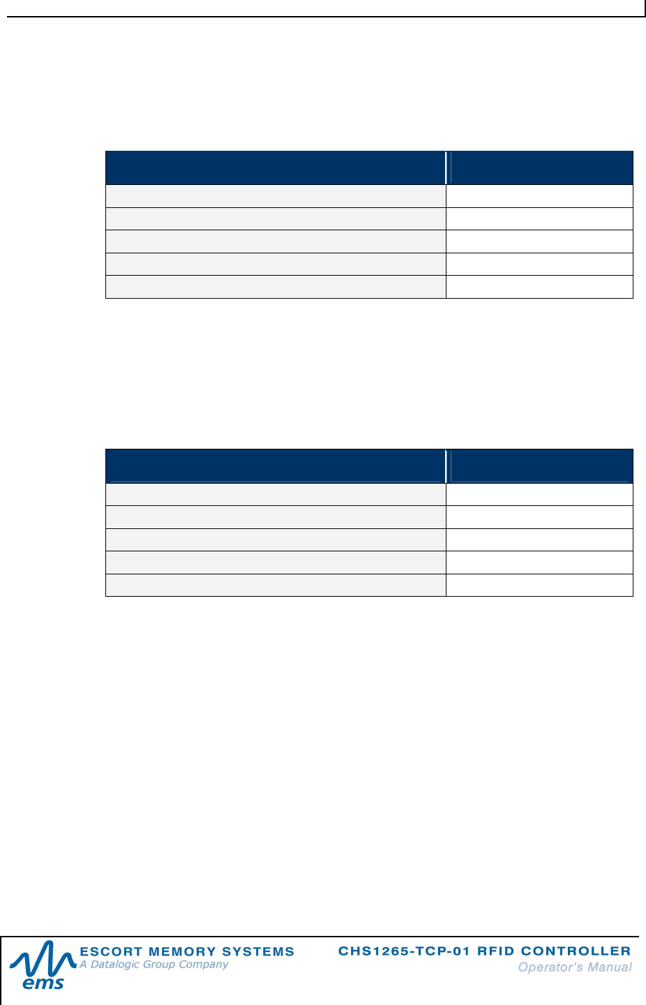
1.2.2 P a ck a g e C o n t e n ts
The CHS1265-TCP-01 product package contains the following components:
PART NUMBER QTY DESCRIPTION
CHS1265-TCP-01 1 Cobalt HS TCP/IP RFID Controller
17-3151 1 CHS1265-TCP-01 - Installation Guide
CBL-1487 1 Field Mountable Connector (5-Pin, female M12, for
connecting to power)
CBL-1531 1 Cap Closure for 5 or 8-pin, male M12 connectors
Table 1-1: Package Contents
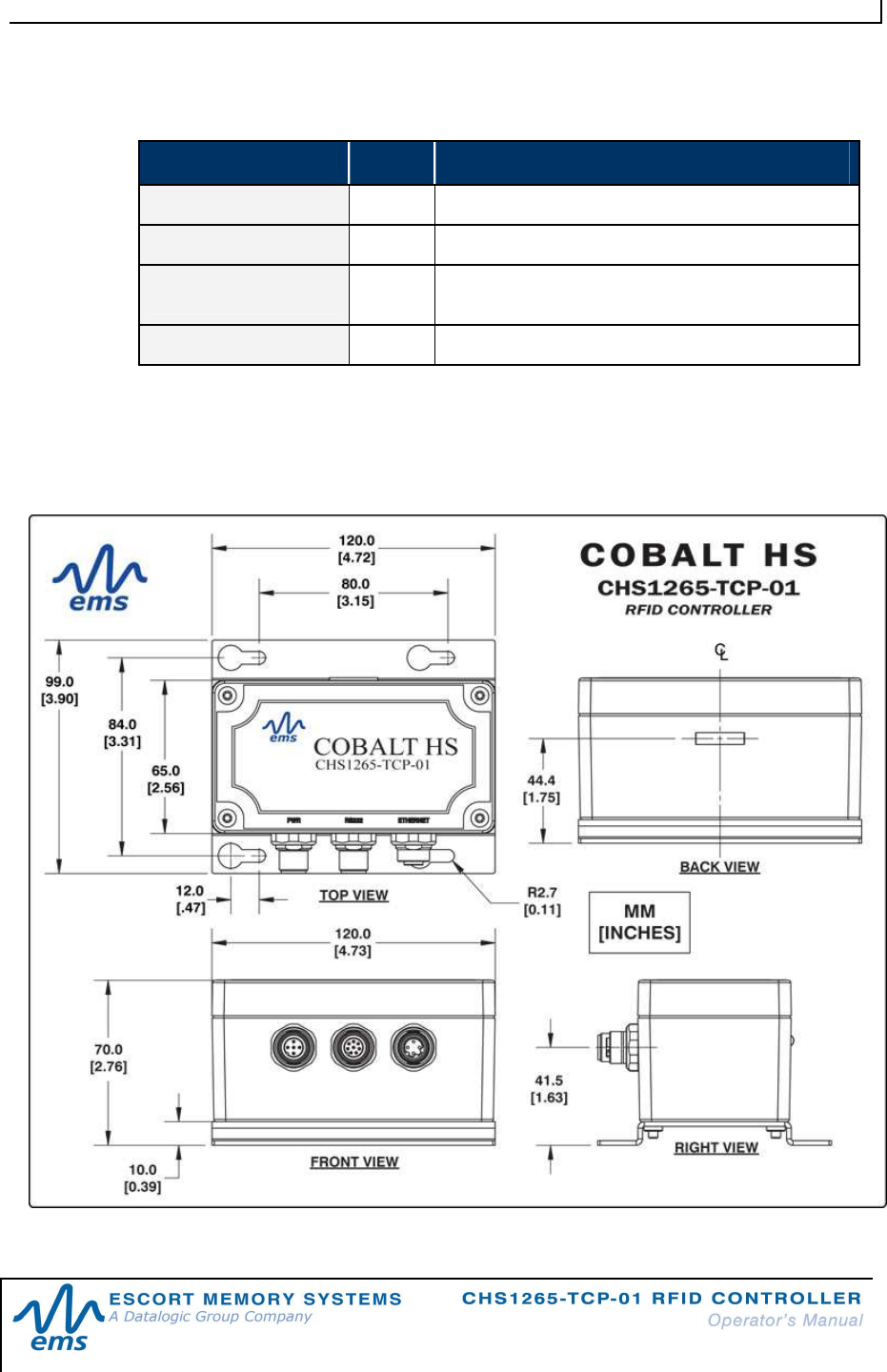
1.3 C
OBALT
HS
-
D
IMENSIONS
Figure 1-1: Cobalt HS - Dimensions
C H A P T E R 1 : G E T T I N G S T A R T E D
P / N : 1 7 - 1 3 3 9 R E V 0 2 ( 0 2 / 0 8 ) P A G E 8 O F 2 9
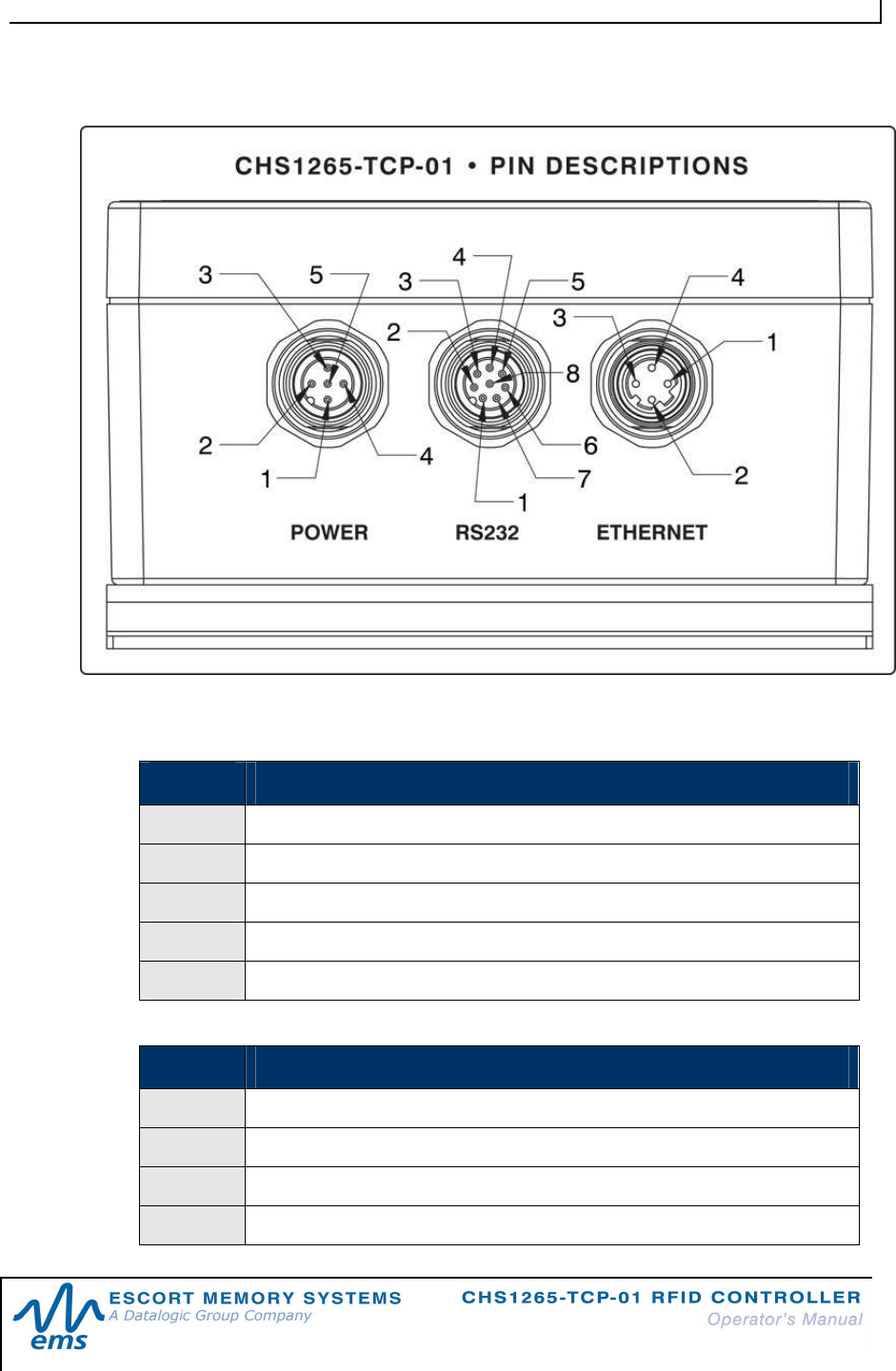
1.4 C
OBALT
HS
-
P
INOUTS
Figure 1-2: CHS1265 - Rear View (Pinouts)
PIN # POWER (5-PIN MALE M12)
1 SHIELD GROUND
2 10~30VDC POWER
3 0VDC POWER GROUND
4 NOT CONNECTED
5 NOT CONNECTED
PIN # RS232 (8-PIN MALE M12)
1 NOT CONNECTED
2 NOT CONNECTED
3 NOT CONNECTED
4 NOT CONNECTED
C H A P T E R 1 : G E T T I N G S T A R T E D
P / N : 1 7 - 1 3 3 9 R E V 0 2 ( 0 2 / 0 8 ) P A G E 9 O F 2 9
5 NOT CONNECTED
6 RX
7 TX
8 SIGNAL GROUND
PIN # ETHERNET (4-PIN FEMALE M12 REVERSE KEYED)
1 TX+
2 RX+
3 TX-
4 RX-
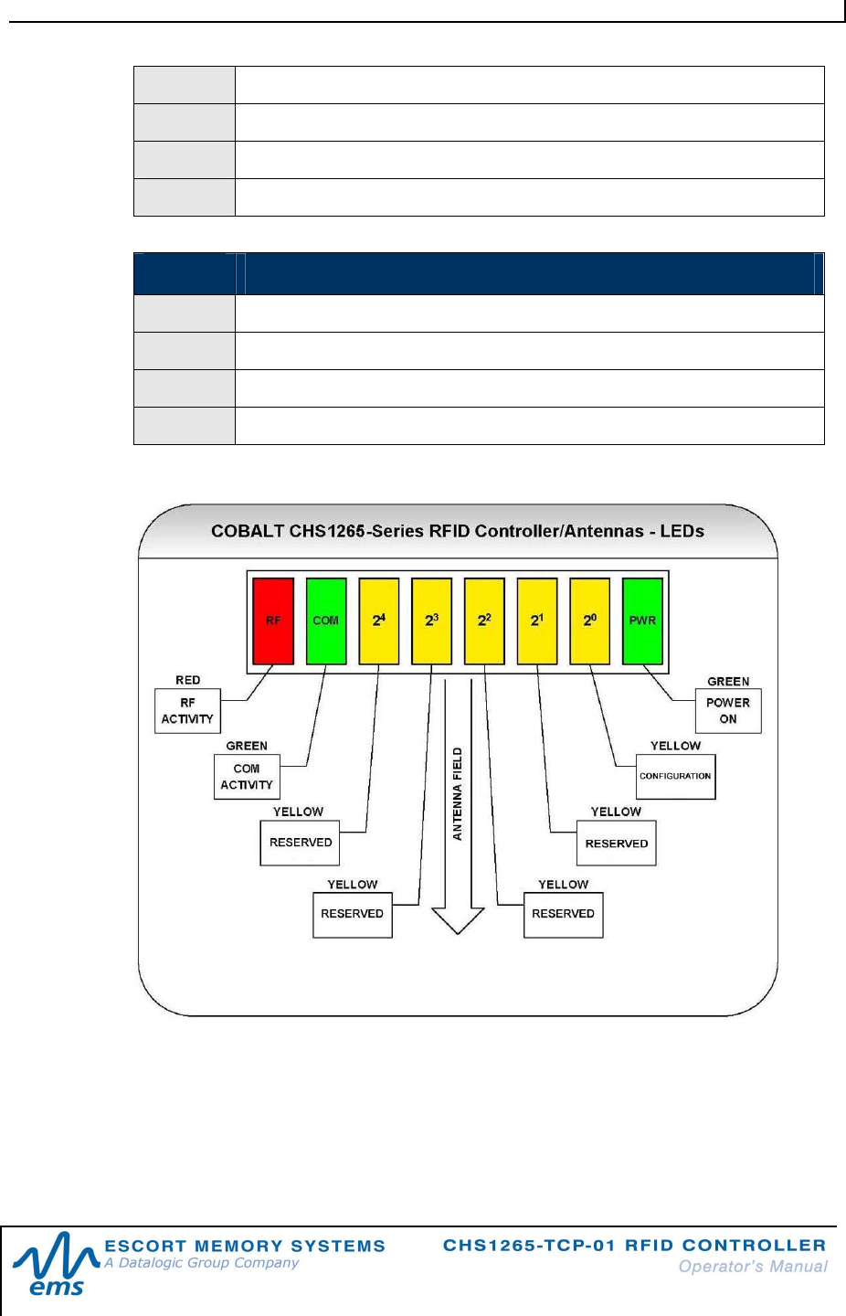
1.4.1 L E D D es c ri p ti o n s
Figure 1-3: LED Description
NOTE: Proximity to metal, water and RF interference can affect read/write range,
performance and results. All RFID applications should be tested to ensure that
adequate RF performance can be achieved.

C H A P T E R 1 : G E T T I N G S T A R T E D
P / N : 1 7 - 1 3 3 9 R E V 0 2 ( 0 2 / 0 8 ) P A G E 1 0 O F 2 9
1.5 P
RE
-I
NSTALLATION
I
NFORMATION
1.5.1 I n s ta l la t io n P r e c a u t i on s
Mounting Guidelines
Avoid mounting the CHS1265-TCP-01 near sources of EMI (electro-magnetic
interference) or near devices that generate high ESD (electro-static discharge)
levels. Avoid routing cables near motors and solenoids.
Do not route cables near unshielded cables or near wiring carrying high voltage
or high current. Cross cables only at perpendicular intersections (if at all)
Power Requirements
The Cobalt HS requires a power supply that can provide 0.5A @ 24VDC (12W).
Network Planning
Plan to perform a test phase and construct a small scale, independent network that
includes only the essential devices required to test your RFID application. It is
recommended that installers attach and configure only one CHS1265-TCP-01 unit at
a time. To avoid possible interference with other devices, do not initially connect your
RFID testing environment to an existing office network.
C H A P T E R 1 : G E T T I N G S T A R T E D
P / N : 1 7 - 1 3 3 9 R E V 0 2 ( 0 2 / 0 8 ) P A G E 1 1 O F 2 9
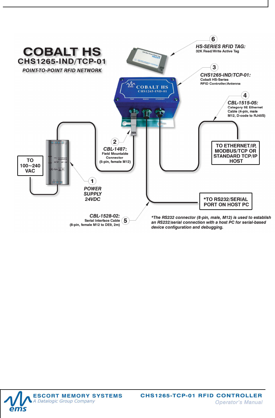
1.5.2 P o i n t - t o -P o i n t N e t w o r k D i a g r a m
Figure 1-4: Cobalt HS - Point-to-Point Network Diagram
1.6 I
NSTALLING THE
CHS1265-TCP-01
1 Unpack and inspect the CHS1265-TCP-01 hardware and accessories. If an
item appears to be damaged, notify your EMS distributor immediately.
2 Securely mount the CHS1265-TCP-01 to your chosen location using four
(4) #10 [M5] screws and matching locking washers and nuts (not included).
The CHS1265-TCP-01 must be mounted so that the unit’s antenna is
properly oriented along the path your RFID tags will travel. The Cobalt HS
should also be aligned in such a manner that the LED indicators can be
seen during normal operation.
3 Attach the 4-pin, male M12 end of a compatible Category 5E Ethernet
cable (EMS P/N: CBL-1515-05) to the connector labeled “ETHERNET” on
the Cobalt HS.
C H A P T E R 1 : G E T T I N G S T A R T E D
P / N : 1 7 - 1 3 3 9 R E V 0 2 ( 0 2 / 0 8 ) P A G E 1 2 O F 2 9
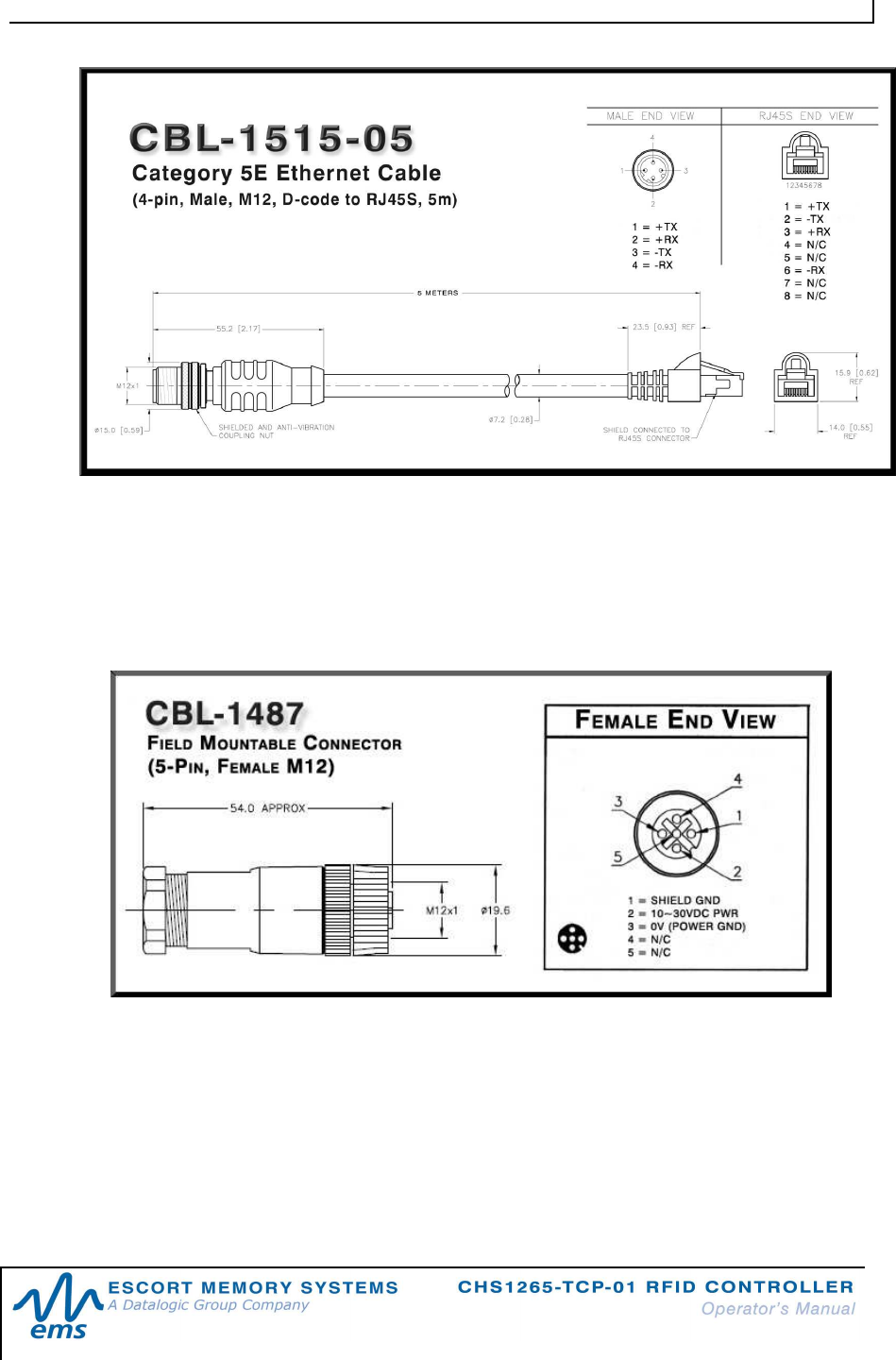
Figure 1-5: CBL-1515-05 CAT5E Ethernet Cable
4 Connect the other end of the Ethernet cable to your application
environment, PLC network or LAN. An Ethernet crossover cable (P/N: CBL-
1479) may be required if connecting the CHS1265-TCP-01 directly to a
host computer (rather than to a network switch, hub or router).
5 Connect the three wires from your power supply to pins 1-3 on the included
5-pin, female, field mountable, M12 mating connector (P/N: CBL-1487).
Figure 1-6: CBL-1487 Field Mountable Connector (for Power)
6 Attach the mating connector to the 5-pin, male M12 connector labeled
“PWR” on the CHS1265-TCP-01.
7 Turn the power supply ON. The green power LED on the Cobalt HS will
illuminate.
8 Repeat these steps for each CHS1265-TCP-01 to be installed.
C H A P T E R 1 : G E T T I N G S T A R T E D
P / N : 1 7 - 1 3 3 9 R E V 0 2 ( 0 2 / 0 8 ) P A G E 1 3 O F 2 9
1.7 Optional Configuration Procedure
Follow the optional steps below to modify the internal configuration of your Cobalt
CHS1265-TCP-01:
9 Connect the 8-pin, female end of an RS232-compatible serial interface
cable (P/N: CBL-1528-02, not included) to the “RS232” connector on the
Cobalt HS.
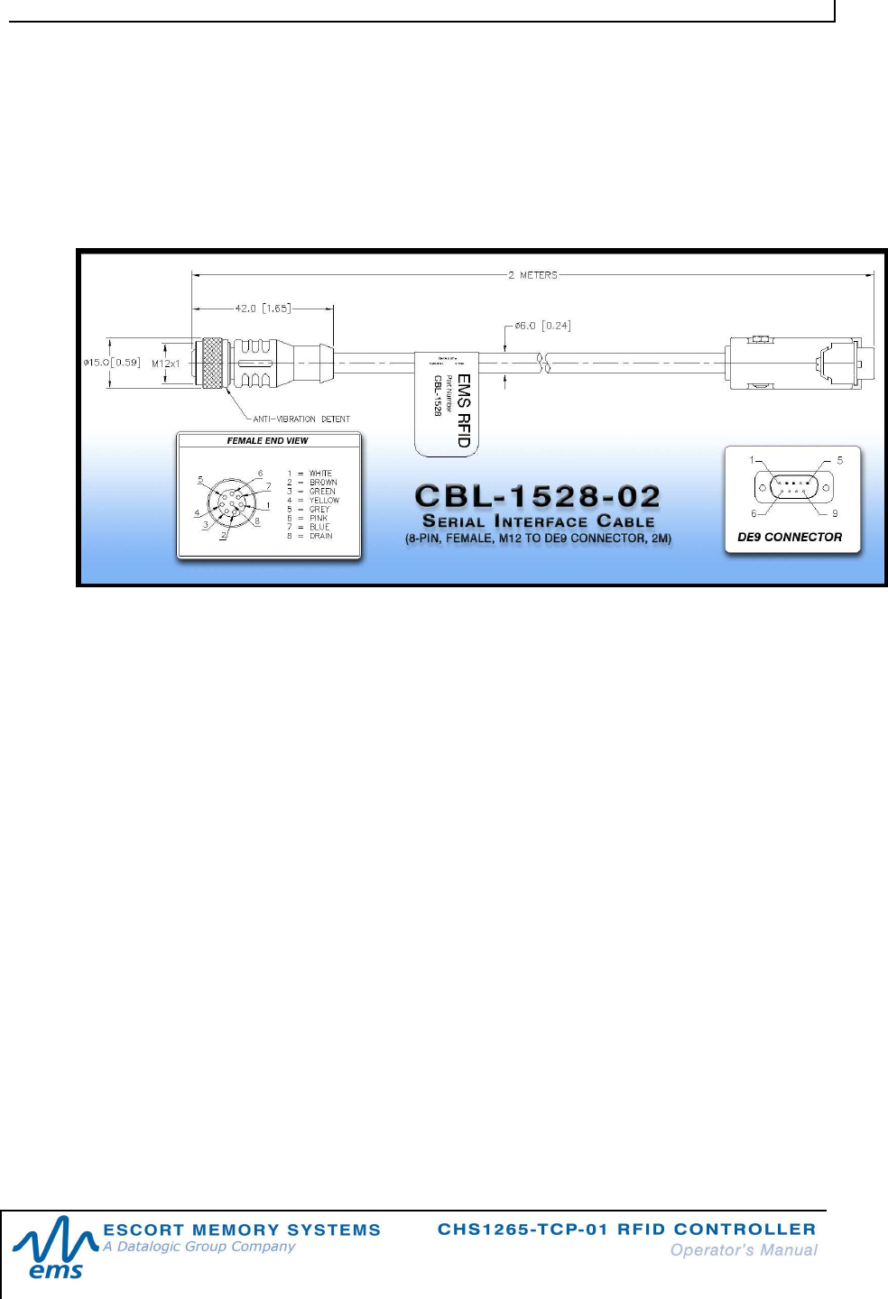
Figure 1-7: CBL-1528-02 Serial Interface Cable
10 Attach the 9-pin, DE9 connector end from the serial interface cable to a
serial port on your host computer.
11 Download the serial version of the Cobalt HF Dashboard Utility from
www.ems-rfid.com. Install and open the application on your host
computer.
12 Cycle power to the Cobalt HS. While the unit is rebooting, the yellow Node
ID 1 LED will flash for approximately five seconds. During this five-second
period, click the button labeled “CONNECT” in the Cobalt HF Dashboard
Utility to establish a serial connection with the Cobalt HS. You will then be
able to use the Cobalt HF Dashboard Utility to further configure the
CHS1265-TCP-01 and send RFID commands to the unit for testing
purposes. Note that when the five-second period expires, the unit boots
normally into TCP/IP mode and the RS232 connector becomes disabled.
C H A P T E R 1 : G E T T I N G S T A R T E D
P / N : 1 7 - 1 3 3 9 R E V 0 2 ( 0 2 / 0 8 ) P A G E 1 4 O F 2 9
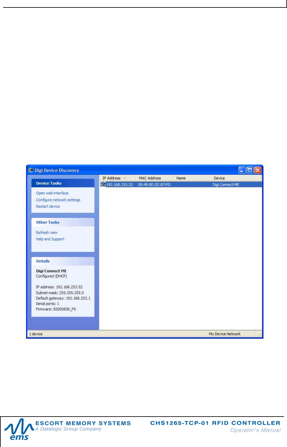
1.8 IP Address Configuration
The Cobalt HS TCP Controller (CHS1265-TCP-01)
is shipped configured to
automatically receive its TCP/IP address from a DHCP server. You need to make
sure that there is a DHCP server on the network, otherwise the device will use a
random generated IP address.
To find out what IP address the device has received, you have to use the “Digi
Device Discovery” software utility.
This utility is available for download at www.ems-rfid.com - filename: “GWY TCP
dgdiscvr.zip.”
Running the Digi Device Discovery will show the IP address of your EMS’ TCP-based
RFID device. You may need to click on “Refresh view” button a few times if the
DHCP server is slow in assigning the IP address to the device.
NOTE: Disable any firewall services running on the host computer. Firewalls can
potentially block communications between the host and the CHS1265-TCP-01.
C H A P T E R 1 : G E T T I N G S T A R T E D
P / N : 1 7 - 1 3 3 9 R E V 0 2 ( 0 2 / 0 8 ) P A G E 1 5 O F 2 9
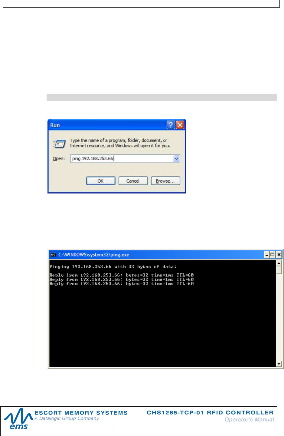
1.9 Network Connection Test
To make sure your PC and the CHS-1265-TCP-01 can communicate over TCP/IP,
you can use the ping.exe tool, a connection test program which is supplied with
Microsoft Windows system. Using a Ping utility helps verify that the CHS1265-TCP-
01 is accessible across the network.
To do that, select Start, then Run and type a command like this:
Ping (IP Address)
where “IP Address” is the same one assigned to the CHS1265-TCP-01 from the Digi
Device Discovery program.
If the CHS1265-IND-01 is online and functioning, you will see a successful response
like this on a DOS pop-up window:
C H A P T E R 1 : G E T T I N G S T A R T E D
P / N : 1 7 - 1 3 3 9 R E V 0 2 ( 0 2 / 0 8 ) P A G E 1 6 O F 2 9
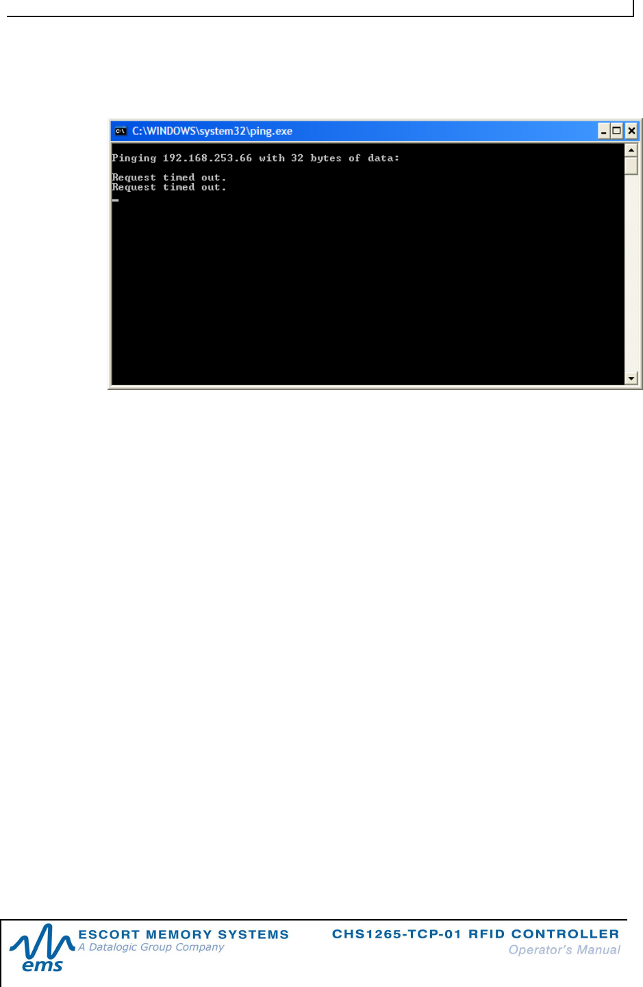
If, on the contrary, the PC and the CHS1265-TCP-01 cannot communicate, you will
see a different message:
In case you get a similar response, you have to make sure the PC and the CHS1265-
TCP-01 have addresses on the same subnet (normally this is managed directly by
the DHCP server).
If you have problems at this point, please consult your system administrator.

C H A P T E R 2 : A B X F A S T R F I D C O M M A N D P R O T O C O L
P / N : 1 7 - 1 3 3 9 R E V 0 2 ( 0 2 / 0 8 ) P A G E 1 7 O F 2 9
CHAPTER 2:
AB
X
FAST
RFID
COMMAND
PROTOCOL
2.1 AB
X
F
AST
C
OMMAND
P
ROTOCOL
O
VERVIEW
In order to execute RFID commands properly, an RFID controller and host computer
must be able to communicate using the same language. The language that is used to
communicate is referred to as the Command Protocol.
The CHS-1265-TCP-01 makes use of the ABx Fast Command Protocol. ABx Fast
has a single-byte oriented packet structure that permits the rapid execution of RFID
commands while requiring the transfer of a minimal number of bytes.
The protocol also supports the inclusion of an optional Checksum byte. When
increased data integrity is required, the checksum should be utilized. See Section
2.2.2.6 for more on using the checksum parameter.
NOTE: HEX NOTATION
In this manual, numbers expressed in Hexadecimal notation are prefaced with “0x”.
For example, the number "10" in decimal is expressed as "0x0A" in hexadecimal.
If need be, the user should refer to a chart containing Hex values and their
corresponding decimal integers.
2.1.1 AB x F a s t C o m ma n d P r o c e d u r e
To issue an RFID command from the host, a packet of data, called the “Command
Packet,” is sent to the RFID controller. The command packet contains information
that instructs the controller to perform a certain task.
The controller automatically parses an incoming data packet, searching for a specific
pair of start characters, known as the “Command Header.” In ABx Fast, the
Command Header characters are 0x02, 0x02. When a Command Header is
recognized, the controller then checks for proper formatting and the presence of a
single-byte “Command Terminator.” In ABx Fast, the Command Terminator byte is
0x03.
Having identified a valid command, the controller will attempt to execute the
instructions, after which it will generate a host-bound response message containing
EITHER the results of the attempted command or an error code if the operation failed.
C H A P T E R 2 : A B X F A S T R F I D C O M M A N D P R O T O C O L
P / N : 1 7 - 1 3 3 9 R E V 0 2 ( 0 2 / 0 8 ) P A G E 1 8 O F 2 9
2.2 AB
X
F
AST
C
OMMAND
P
ROTOCOL
P
ACKET
S
TRUCTURES
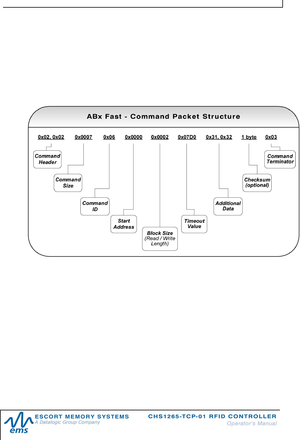
2.2.1 AB x F a s t C o m ma n d P a c k e t S t r uc t u r e
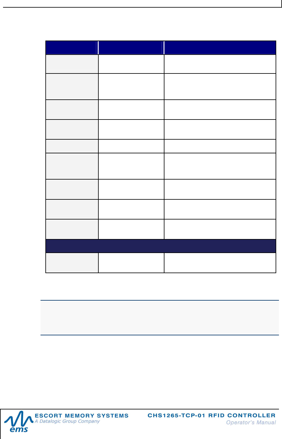
The packet structure of all ABx Fast RFID commands contains certain basic
elements, including Command Header, Command Size, Command ID and
Command Terminator. Packet element and parameter availability depends on the
command being performed.
Figure 2-1: ABx Fast - Command Packet Structure
C H A P T E R 2 : A B X F A S T R F I D C O M M A N D P R O T O C O L
P / N : 1 7 - 1 3 3 9 R E V 0 2 ( 0 2 / 0 8 ) P A G E 1 9 O F 2 9
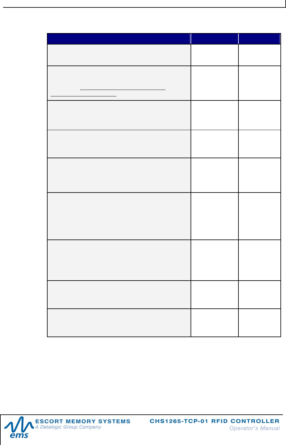
ABx Fast Command Packet Structure
COMMAND PACKET ELEMENT CONTENT SIZE
COMMAND HEADER:
These are the first two bytes of an ABx Fast command.
0x02, 0x02 2 bytes
COMMAND SIZE:
This two-byte integer defines the number of bytes in
the packet (excluding Header, Command Size,
Checksum and Terminator).
0x0007 +
(number of
bytes of
additional data)
2-byte integer
COMMAND ID:
This single-byte value indicates the RFID command to
execute.
0x06
(Write Data) 1 byte
START ADDRESS:
This two-byte integer indicates the location of tag
memory where a read or write operation shall begin.
0x0000 2-byte integer
BLOCK SIZE:
This two-byte integer represents the number of bytes
that are to be read from or written to the RFID tag
during the operation.
0x0001 2-byte integer
TIMEOUT VALUE:
This two-byte integer indicates the maximum length of
time for which the controller will attempt to complete
the command. Measured in milliseconds, this value can
have a range of 0x0001 to 0xFFFE or between 1 and
65,534 msecs.
0x07D0
(0x07D0 =
2000 x .001 = 2
seconds)
2-byte integer
ADDITIONAL DATA:
This parameter uses one byte to hold a single
character for fill operations and supports the use of
multiple bytes when several characters are needed for
write commands (when applicable).
0x00 1 or more
bytes
CHECKSUM:
This optional parameter holds a single-byte checksum
(only applicable when using ABx Fast with Checksum).
Optional 1 byte (when
applicable)
COMMAND TERMINATOR:
The single-byte command packet terminator is always
0x03 for ABx Fast.
0x03 1 byte
Table 2-1: ABx Fast Command Packet Structure
C H A P T E R 2 : A B X F A S T R F I D C O M M A N D P R O T O C O L
P / N : 1 7 - 1 3 3 9 R E V 0 2 ( 0 2 / 0 8 ) P A G E 2 0 O F 2 9
2.2.2 AB x F a s t C o m ma n d P a c k e t E le m e n ts
2.2 . 2 .1 C o mm a nd S iz e
The ABx Fast protocol requires that the byte count, known as the Command Size,
be specified as a two-byte integer within each command packet. To calculate the
Command Size, add the total number of bytes within the command packet while
excluding the two byte Command Header, the two byte Command Size, the one
byte Checksum (if present) and the one byte Command Terminator (see example
below).
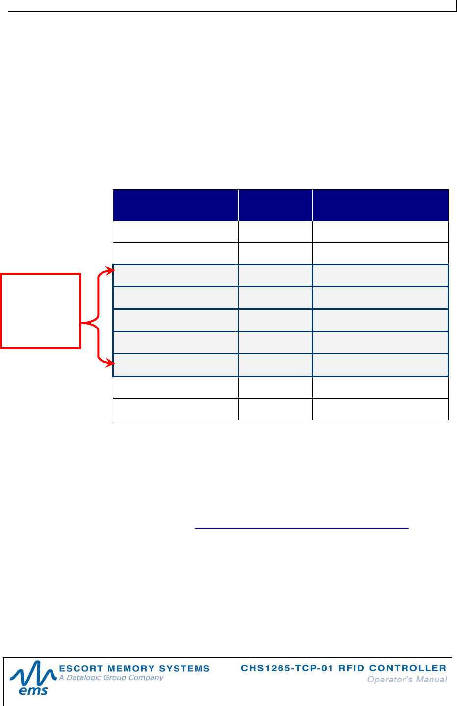
COMMAND PACKET
ELEMENT # OF BYTES INCLUDED IN
COMMAND SIZE?
Command Header 2 No
Command Size 2 No
Command ID 1 Yes
Start Address 2 Yes
Read/Block Size 2 Yes
Timeout Value 2 Yes
Additional Data Bytes 1 Yes (if present)
Checksum 1 No
Command Terminator 1 No
Table 2-2: ABx Fast Command Size Parameter
In the above command packet, there are eight bytes of data (located between the
Command Size parameter and the Checksum parameter) that are included in the
Command Size. Therefore, the Command Size for this example is 0x0008.
2.2 . 2 .2 C o mm a nd I D
The one-byte Command ID parameter identifies the Hex value of the RFID
command to perform (see Chapter 2 – Section 2.3: RFID Commands Table.)
2.2 . 2 .3 St a r t A dd r e ss
The Start Address parameter holds a two-byte integer representing the tag memory
address location where a read or write operation is to begin.
2.2 . 2 .4 B lo c k S i z e (R e a d/Wr i t e L en g t h )
The two-byte Block Size parameter (which is also sometimes called the Read /
Write Length parameter) indicates the number of bytes that are to be read from or
written to the RFID tag.
Command
Size =
number of
bytes in these
fields

C H A P T E R 2 : A B X F A S T R F I D C O M M A N D P R O T O C O L
P / N : 1 7 - 1 3 3 9 R E V 0 2 ( 0 2 / 0 8 ) P A G E 2 1 O F 2 9
2.2 . 2 .5 Ti m eo u t Val u e
Most ABx Fast commands include a two-byte Timeout Value, which is used to limit
the length of time that the controller will attempt to complete the specified operation.
The Timeout Value is measured in 1-millisecond increments and has a maximum
supported value of 0xFFFE or 65,534 milliseconds (which is slightly longer than one
minute).
Setting a long Timeout Value does not necessarily mean that a command will take
any longer to execute. This value only represents the period of time for which the
controller will attempt execution of the command.
IMPORTANT:
During write commands, the tag must remain within the antenna’s RF field until the
write operation completes successfully, or until the Timeout Value has expired.
If a write operation is not completed before the tag leaves the controller’s RF field, data
may be incompletely written.
2.2 . 2 .6 C h ec k su m
The ABx Fast Command Protocol supports the inclusion of an additional Checksum
byte that is used to verify the integrity of data being transmitted between host and
controller.
The Checksum is calculated by adding together (summing) the byte values in the
command packet (less the Command Header, Checksum and Command
Terminator parameters), and then subtracting the total byte sum from 0xFF.
Therefore, when the byte values of each parameter (from Command Size to
Checksum) are added together, the byte value sum will equal 0xFF.
C H A P T E R 2 : A B X F A S T R F I D C O M M A N D P R O T O C O L
P / N : 1 7 - 1 3 3 9 R E V 0 2 ( 0 2 / 0 8 ) P A G E 2 2 O F 2 9
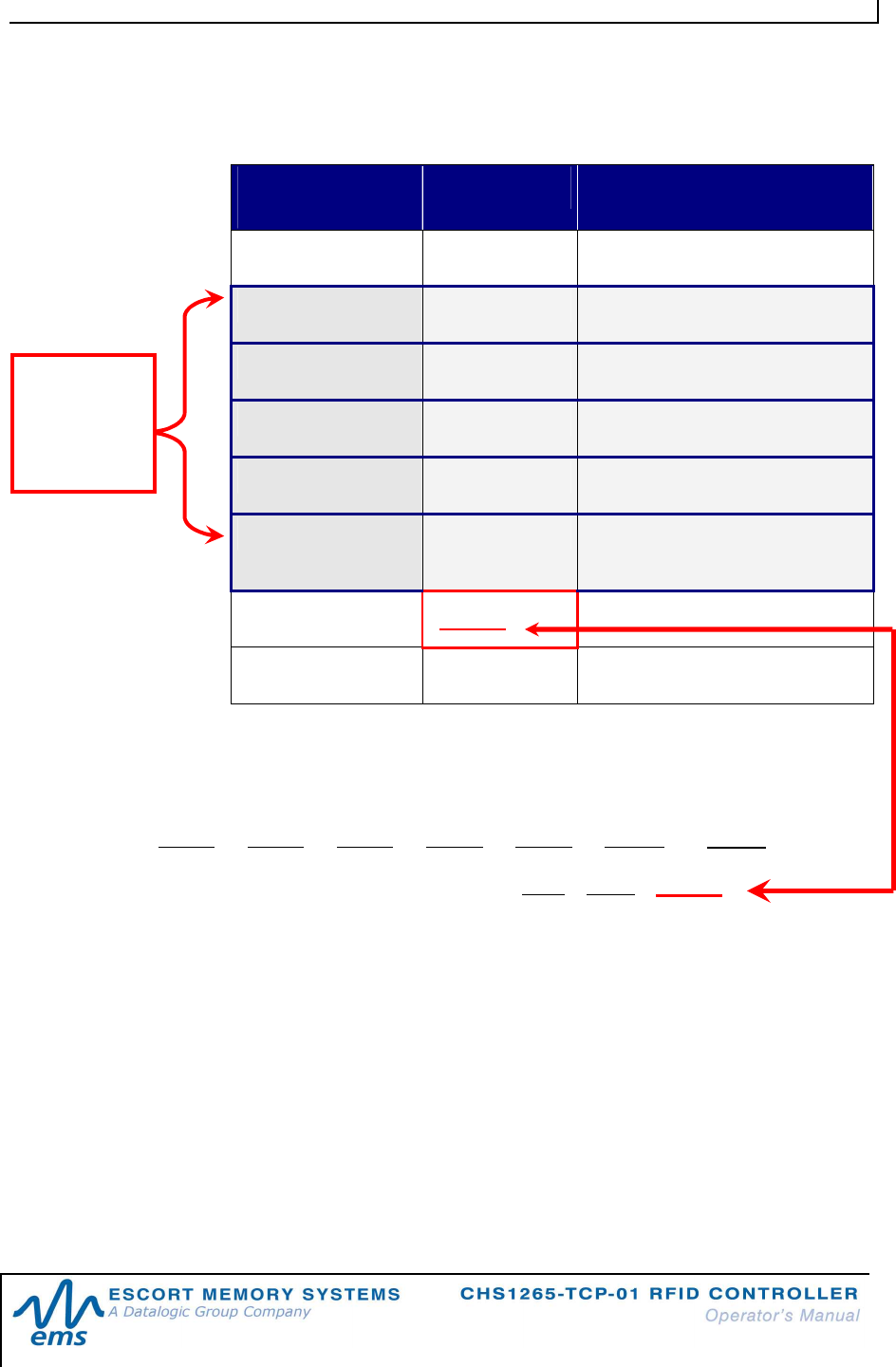
CH E C K S U M EX A M P L E
The following example depicts Command 0x05 (Read Data) when using a
Checksum.
COMMAND
ELEMENT CONTENTS USED IN CHECKSUM
Header 0x02, 0x02 n/a
Command Size 0x0007 0x00, 0x07
Command ID 0x05 0x05
Start Address 0x0001 0x00, 0x01
Block Size 0x0004 0x00, 0x04
Timeout Value 0x07D0 0x07, 0xD0
Checksum
0 x 1 7
n/a
Terminator 0x03 n/a
Table 2-3: ABx Fast - Checksum Example
Add the byte values from the Command Size, Command ID, Start Address, Block
Size and Timeout Value parameters together and subtract from 0xFF. The resulting
value will be the Checksum.
[ 0 x 0 7 + 0 x 0 5 + 0 x 0 1 + 0 x 0 4 + 0 x 0 7 + 0 x D 0 ] = 0 x E 8
The checksum equation is: [0xFF – 0xE8] =
0 x 1 7
Checksum
= [0xFF –
(sum of
these fields)]
C H A P T E R 2 : A B X F A S T R F I D C O M M A N D P R O T O C O L
P / N : 1 7 - 1 3 3 9 R E V 0 2 ( 0 2 / 0 8 ) P A G E 2 3 O F 2 9
2.2.3 AB x F a s t Re s p o n s e P a c k e t S t r u c t u r e
After performing a command, the controller, in most cases, will generate a host-
bound response packet. ABx Fast responses contain a Response Header,
Response Size, Command Echo, one or more Response Values / Retrieved Data
(when applicable), and a Response Terminator.
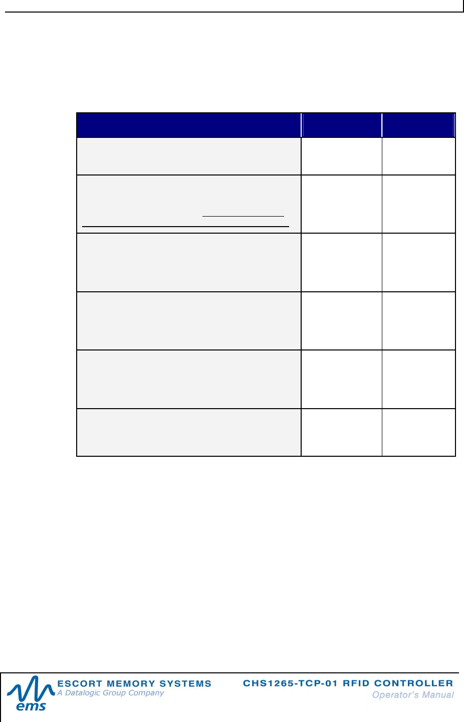
RESPONSE PACKET ELEMENT CONTENT SIZE
RESPONSE HEADER:
The first two bytes of an ABx Fast response packet
0x02, 0x02 2 bytes
RESPONSE SIZE:
This two-byte integer indicates the total number of
bytes in the response packet (excluding Response
Header, Response Size, Checksum and Terminator).
0x0001 +
(number of bytes
of retrieved data)
2-byte integer
COMMAND ECHO:
This single-byte parameter reiterates the Hex value
of the command for which the response packet was
generated.
0x06 1 byte
RESPONSE VALUES / RETRIEVED DATA:
This parameter is used to hold one or more bytes of
the data that was requested by the command (when
applicable).
Data 1 or more
bytes (when
applicable)
CHECKSUM:
This optional parameter holds a single-byte
checksum (only applicable when using ABx Fast with
Checksum).
Optional 1 byte
(when
applicable)
RESPONSE TERMINATOR:
Single-byte response packet terminator (always
0x03)
0x03 1 byte
Table 2-4: ABx Fast Response Packet Structure
C H A P T E R 2 : A B X F A S T R F I D C O M M A N D P R O T O C O L
P / N : 1 7 - 1 3 3 9 R E V 0 2 ( 0 2 / 0 8 ) P A G E 2 4 O F 2 9
2.2.4 Ab x F a s t E r r o r R e s p o n s e S t r uc t u r e
ABx Fast error responses contain a two-byte Header, a two-byte Response Size
parameter followed by a single-byte Error Flag (0xFF) and a single-byte Error Code
parameter, which identifies the error that occurred.
ERROR RESPONSE ELEMENT CONTENT
Header 0x02, 0x02
Response Size 0x0002
Error Flag 0xFF
Error Code Single-byte Error Code
Terminator 0x03
Table 2-5: ABx Fast - Error Response Structure
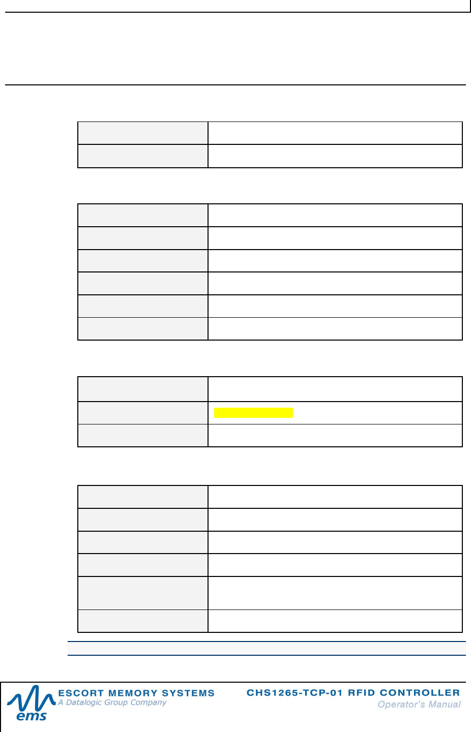
AB X F AS T ER R OR R E SP O N S E E X AM P L E
Below is an example of an ABx Fast error response for a failed Write Data command
(error code 0x06).
ERROR RESPONSE ELEMENT CONTENT
Header 0x02, 0x02
Response Size 0x0002
Error Flag 0xFF
Error Code 0x06
Terminator 0x03
C H A P T E R 2 : A B X F A S T R F I D C O M M A N D P R O T O C O L
P / N : 1 7 - 1 3 3 9 R E V 0 2 ( 0 2 / 0 8 ) P A G E 2 5 O F 2 9
2.3 RFID
C
OMMANDS
T
ABLE
COMMAND ID COMMAND NAME DESCRIPTION
0x04 F i l l T a g Fills a specified tag address range with a
one-byte value
0x05 R e a d D a t a Reads a specified length of data from a
contiguous (sequential) area of tag
memory
0x06 W r i te Da t a Writes a specified number of bytes to a
contiguous area of tag memory
0x08 T a g S e a r c h Instructs the controller to search for a tag
in its RF field
0x35 R e s e t C o n t r o l l e r
Resets power to the controller
0x36 S e t C o nt r o l l e r
C on f i g u r a t i o n
Used to set (configure or modify) the
controller’s configuration parameters and
settings
0x37 G e t Co n t r o l l e r
C on f i g u r a t i o n Retrieves the controller’s configuration
settings
0x38 G e t Co n t r o l l e r
I nf o Retrieves hardware, firmware and serial
number information from the controller
0x72 E x e c u t e
C on t r o l l e r M a c r o
Instructs the controller to execute one of
its eight macros
RFID CONTROLLER COMMANDS
0x5F R es e t T ag
B at t e r y C o u n t e r Resets the value of a tag’s internal battery
counter to zero (0x00)
Table 2-6: RFID Commands Table
NOTE:
For more information regarding ABx Fast RFID commands and error codes, see
publication 17-1333: ABx Fast Command Protocol – Reference Manual, available
online at www.ems-rfid.com.
C H A P T E R 2 : A B X F A S T R F I D C O M M A N D P R O T O C O L
P / N : 1 7 - 1 3 3 9 R E V 0 2 ( 0 2 / 0 8 ) P A G E 2 6 O F 2 9
CO M M AN D 0X5F - DE S C R I P T I O N
The Reset Tag Battery Counter Command resets the value of a tag’s Battery
Counter to zero (0x00). This command is designed to be used when replacing the
batteries in an active RFID tag.
Located at tag address 0x0000, the Battery Counter is a one-byte value that
indicates the number of operating hours that the tag has been in use since it has last
had its internal batteries replaced. When this value reaches 0x0F, battery life is in a
condition of decay (batteries should be replaced after the tag has accumulated 15
hours of use).
To retrieve the Battery Counter Value, execute Command 0x05 (Read Data) and
note the value stored at address 0x0000 on the tag. Reading address zero on the tag
should only be performed by one station in a typical assembly line.
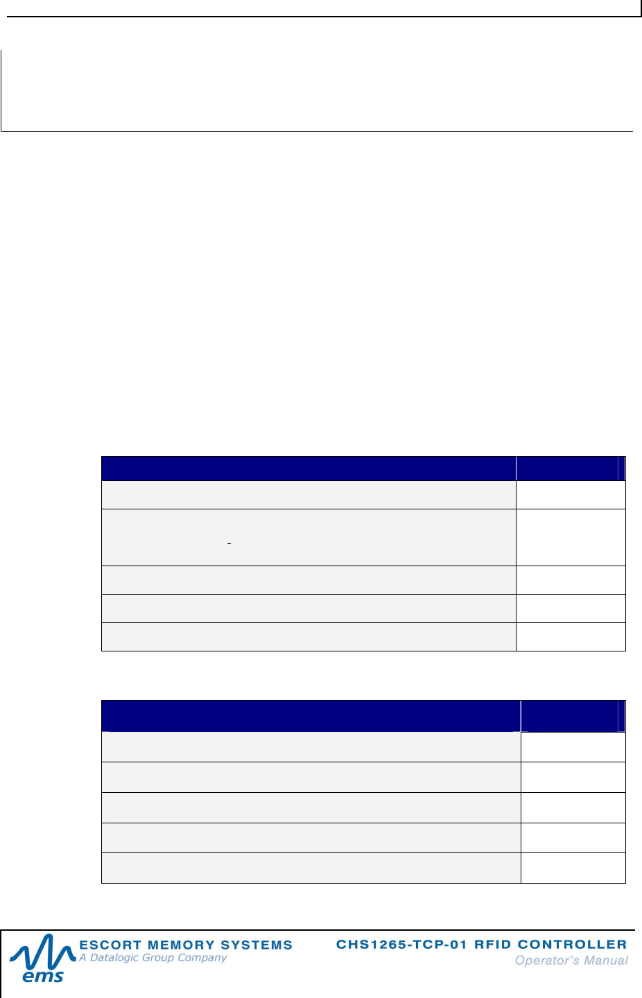
CO M M AN D 0X5F - AB X FAS T EX AM P L E
This example resets the tag’s battery counter to zero (0x00).
Comm a nd f ro m Ho st
PARAMETER FIELD CONTENT
Header (0x02, 0x02 = header for all ABx Fast commands) 0x02, 0x02
Command Size (2-byte integer for the number of bytes in the
command - excluding Header, Command Size, Checksum and
Terminator)
0x0001
Command ID (1-byte value for the command to perform) 0x5F
Checksum (1-byte optional) Optional
Terminator (0x03 = terminator for all ABx Fast commands) 0x03
Res p o ns e f r o m C ont r ol l e r
PARAMETER FIELD CONTENT
Header 0x02, 0x02
Response Size 0x0001
Command Echo 0x5F
Checksum Optional
Terminator 0x03
AB
X
F
AS T
C
O M M A N D
0
X
5F:
RESET
TAG
BAT TE RY
COUNTER
C H A P T E R 3 : S T A N D A R D T C P / I P P R O T O C O L
P / N : 1 7 - 1 3 3 9 R E V 0 2 ( 0 2 / 0 8 ) P A G E 2 7 O F 2 9
CHAPTER 3:
STANDARD
TCP/IP
PROTOCOL
3.1 S
TANDARD
TCP/IP
O
VERVIEW
Communication with the CHS1265-TCP-01 is through the TCP/IP protocol.
Here the CHS1265-TCP-01 acts as server and the host or PLC acts as client.
Standard
TCP/IP sessions are established between the host and the CHS1265-TCP-
01 via user supplied TCP/IP client software. A TCP/IP session generally consists of
three stages: connection setup, data transactions and connection termination.
The client software is responsible for opening, maintaining, and closing all TCP/IP
sessions. After establishing a successful connection, communications between the
host and the CHS1265-TCP-01 can proceed.
If an existing connection terminates unexpectedly, the CHS1265-TCP-01 will not
attempt to contact the client software or re-establish a connection. When
communication is no longer necessary, it is the responsibility of the client side
application to terminate the connection.
NOTE:
The TCP/IP client software (on the host or PLC) must connect to the TCP/IP
server (CHS1265-TCP-01) on port 2101.
Maximum number of bytes that can be transferred to/from an RFID tag per
read/write cycle: 8192.
A P P E N D I X A : T E C H N I C A L S P E C I F I C A T I O N S
P / N : 1 7 - 1 3 3 9 R E V 0 2 ( 0 2 / 0 8 ) P A G E 2 8 O F 2 9
APPENDIX
A:
TECHNICAL
SPECIFICATIONS
EL E CTRIC AL
Supply Voltage 18~30VDC
Power Consumption 12W (500mA @ 24VDC)
COM M U N IC AT I O N
Communication Interfaces TCP/IP
RFID Interface Cobalt HS-Series RFID System
RF Output Power 1W
Air Protocols ISO 15693, ISO 14443 A
Air Protocol Speed 26.5k Baud/106k Baud with CRC error detection
Baud Rates 9600 (default), 19.2k, 38.4k, 57.6k, 115.2k
M ECH AN I C AL
Dimensions (L x W x H) 120mm x 99mm x 70mm (4.72in x 3.90in x 2.76in)
Weight 440 grams (.97 lbs)
Enclosure Polycarbonate / Powder-coated Aluminum
EN V I R ON M E NT AL
Operating Temperature -20° to 50°C (-4° to 122°F),
Storage Temperature -40° to 85°C (-40° to 185°)
Humidity 100%
Protection Class IP66
Shock Resistance IEC 68-2-27 Test EA 30g, 11 milliseconds, 3 shocks each
axis
Vibration Resistance IEC 68-2-6 Test FC 1.5mm; 10 to 55Hz; 2 hours each axis
NOTE: Specifications are subject to change without notice.
E M S W A R R A N T Y
P / N : 1 7 - 1 3 3 9 R E V 0 2 ( 0 2 / 0 8 ) P A G E 2 9 O F 2 9
EMS
WARRANTY
Escort Memory Systems warrants that all products of its own manufacturing conform to Escort
Memory Systems’ specifications and are free from defects in material and workmanship when
used under normal operating conditions and within the service conditions for which they were
furnished. The obligation of Escort Memory Systems hereunder shall expire one (1) year after
delivery, unless otherwise specified, and is limited to repairing, or at its option, replacing without
charge, any such product which in Escort Memory Systems’ sole opinion proves to be defective
within the scope of this Warranty. In the event Escort Memory Systems is not able to repair or
replace defective products or components within a reasonable time after receipt thereof, Buyers
shall be credited for their value at the original purchase price. Escort Memory Systems must be
notified in writing of the defect or nonconformity within the warranty period and the affected
product returned to Escort Memory Systems factory or to an authorized service center within
thirty (30) days after discovery of such defect or nonconformity. Shipment shall not be made
without prior authorization by Escort Memory Systems.
This is Escort Memory Systems' sole warranty with respect to the products delivered hereunder.
No statement, representation, agreement or understanding oral or written, made by an agent,
distributor, representative, or employee of Escort Memory Systems which is not contained in this
warranty, will be binding upon Escort Memory Systems, unless made in writing and executed by
an authorized Escort Memory Systems employee.
Escort Memory Systems makes no other warranty of any kind what so ever, expressed or
implied, and all implied warranties of merchantability and fitness for a particular use which
exceed the aforementioned obligation are here by disclaimed by Escort Memory Systems and
excluded from this agreement. Under no circumstances shall Escort Memory Systems be liable
to Buyer, in contract or in tort, for any special, indirect, incidental, or consequential damages,
expenses, losses or delay however caused. Equipment or parts which have been subject to
abuse, misuse, accident, alteration, neglect, unauthorized repair or installation are not covered
by warranty. Escort Memory Systems shall make the final determination as to the existence and
cause of any alleged defect. No liability is assumed for expendable items such as lamps and
fuses. No warranty is made with respect to equipment or products produced to Buyer’s
specification except as specifically stated in writing by Escort Memory Systems in the contract
for such custom equipment. This warranty is the only warranty made by Escort Memory
Systems with respect to the goods delivered hereunder, and may be modified or amended only
by a written instrument signed by a duly authorized officer of Escort Memory Systems and
accepted by the Buyer.
Extended warranties of up to four years are available for purchase for most Escort Memory
Systems products. Contact Escort Memory Systems or your distributor for more information.
Copyright © 2007 Escort Memory Systems, all rights reserved