Balluff COBALT-01 RFID Reader / Writer (HF-CNTL-422-01) User Manual Cobalt Operation Manual
BALLUFF inc RFID Reader / Writer (HF-CNTL-422-01) Cobalt Operation Manual
UserManual.wiki
>
Balluff
>
COBALT-01 User Manual
>
User Manual
Contents
1.
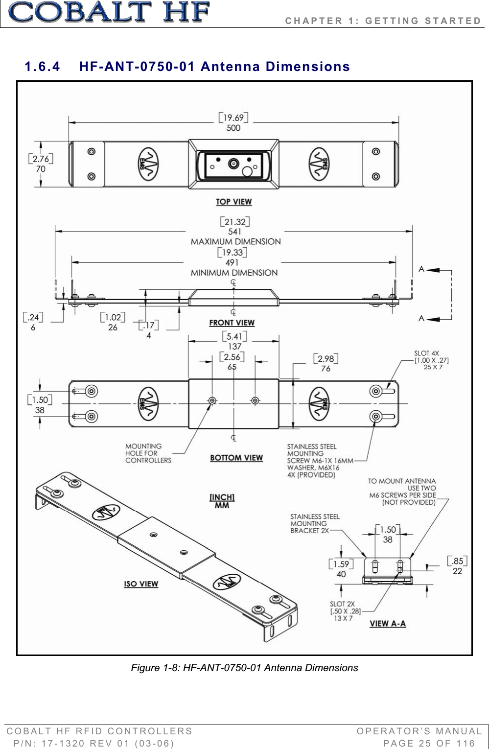
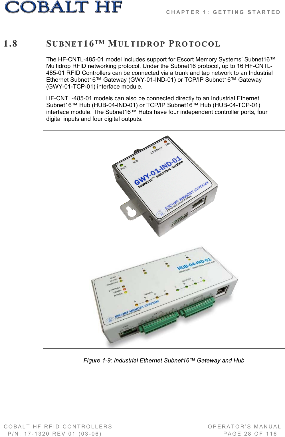
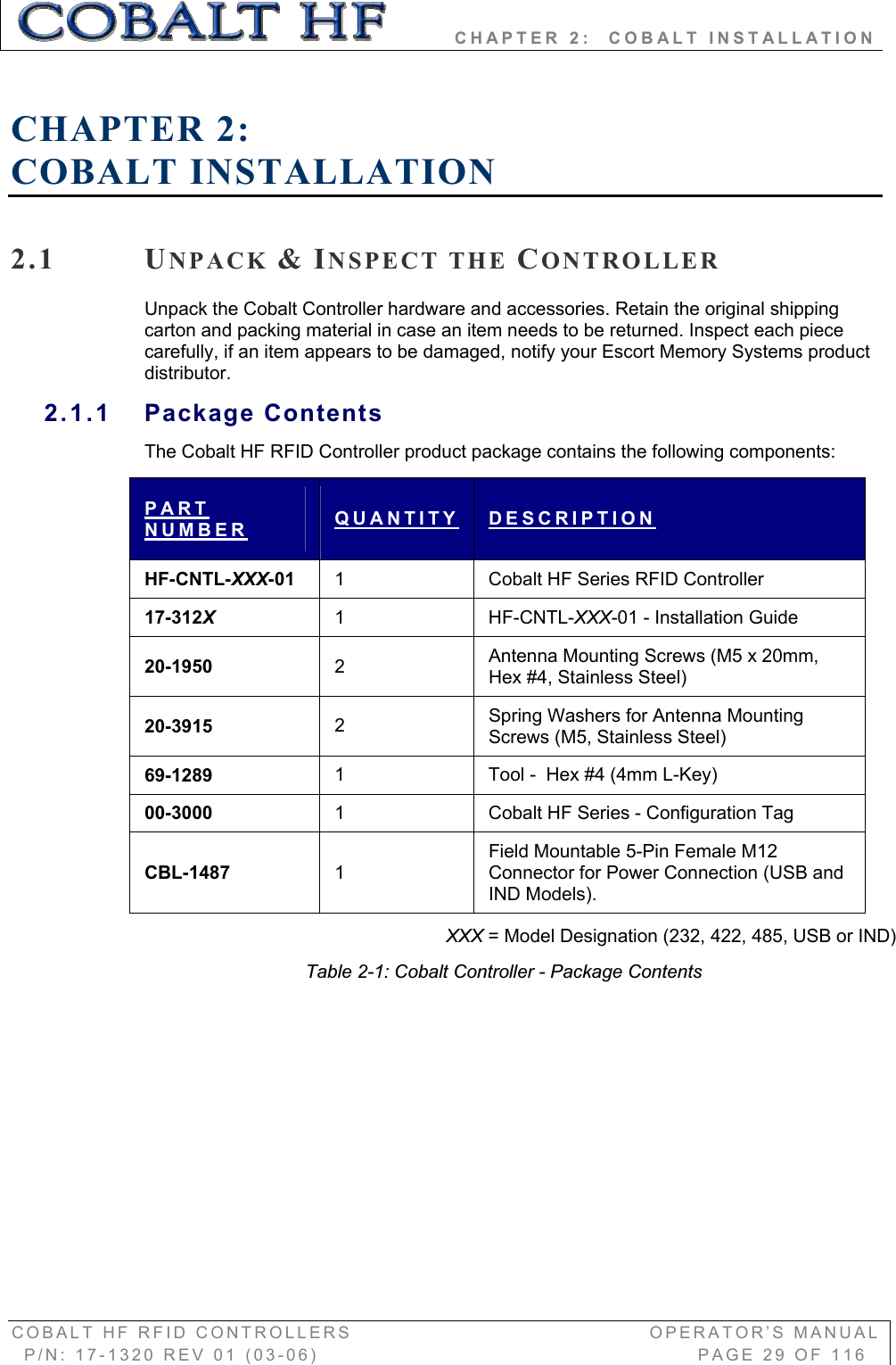
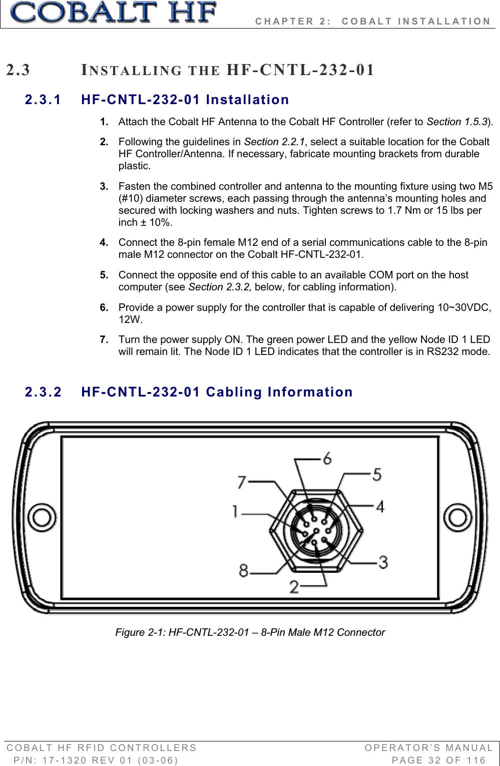
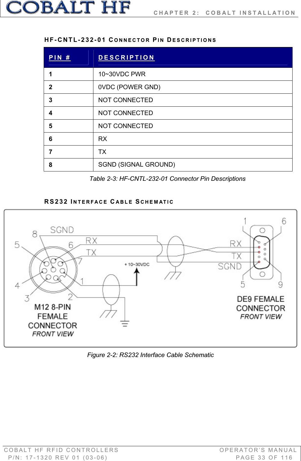
User Manual
2.
Usr Manual
User Manual
Navigation menu
Upload a User Manual
Namespaces
Wiki Guide
HTML
PDF
Info
Views
User Manual
Discussion / Help
Navigation