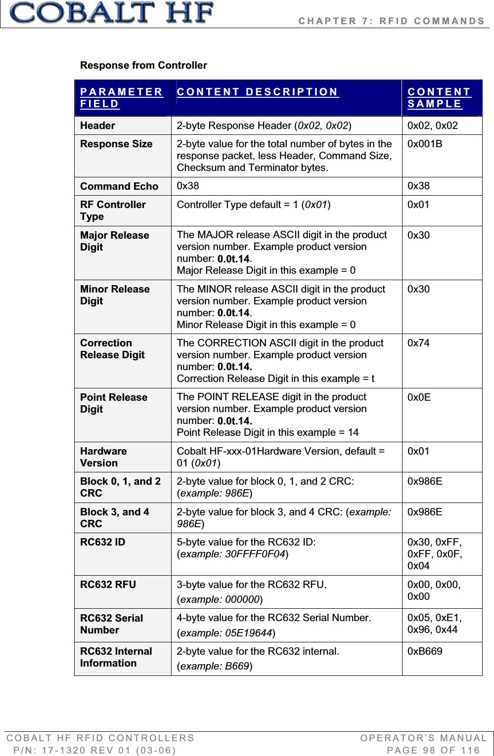
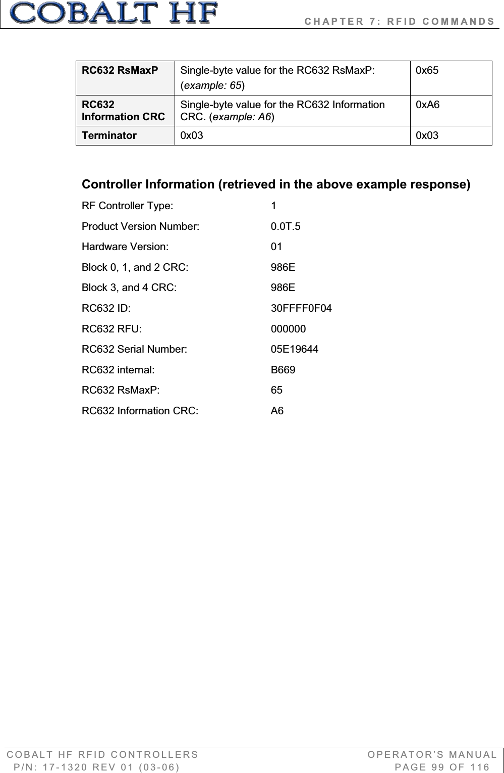
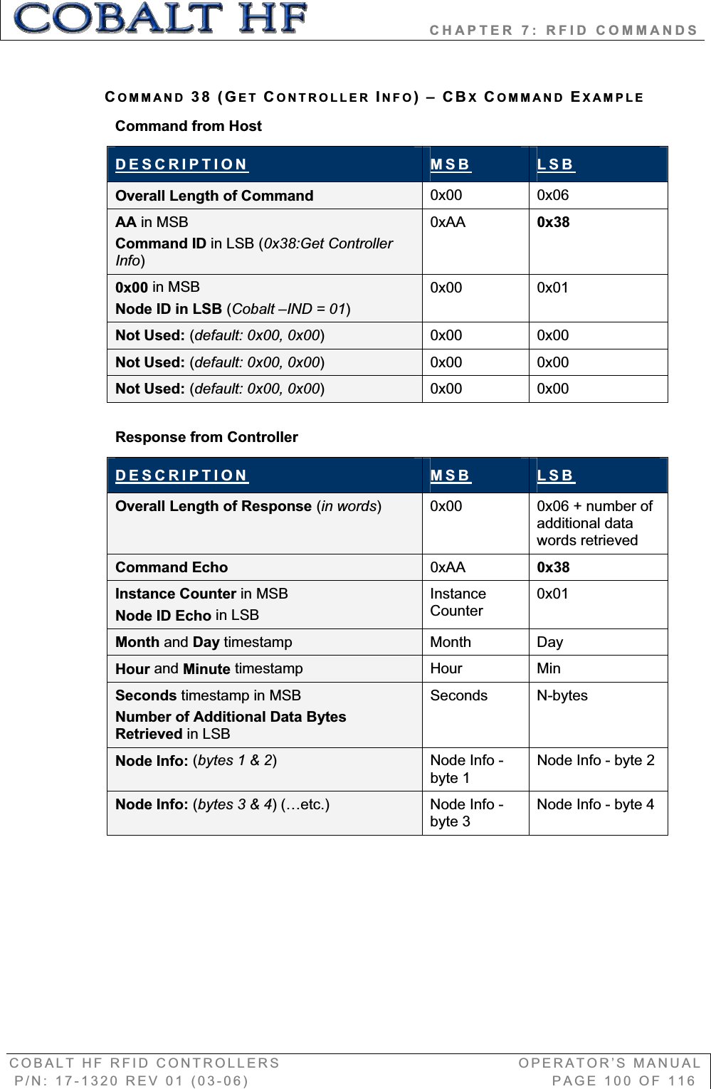
Balluff COBALT-01 RFID Reader / Writer (HF-CNTL-422-01) User Manual Cobalt HF Ops Manual17 1320 REV01
BALLUFF inc RFID Reader / Writer (HF-CNTL-422-01) Cobalt HF Ops Manual17 1320 REV01
Balluff >
Contents
- 1. User Manual
- 2. Usr Manual
Usr Manual

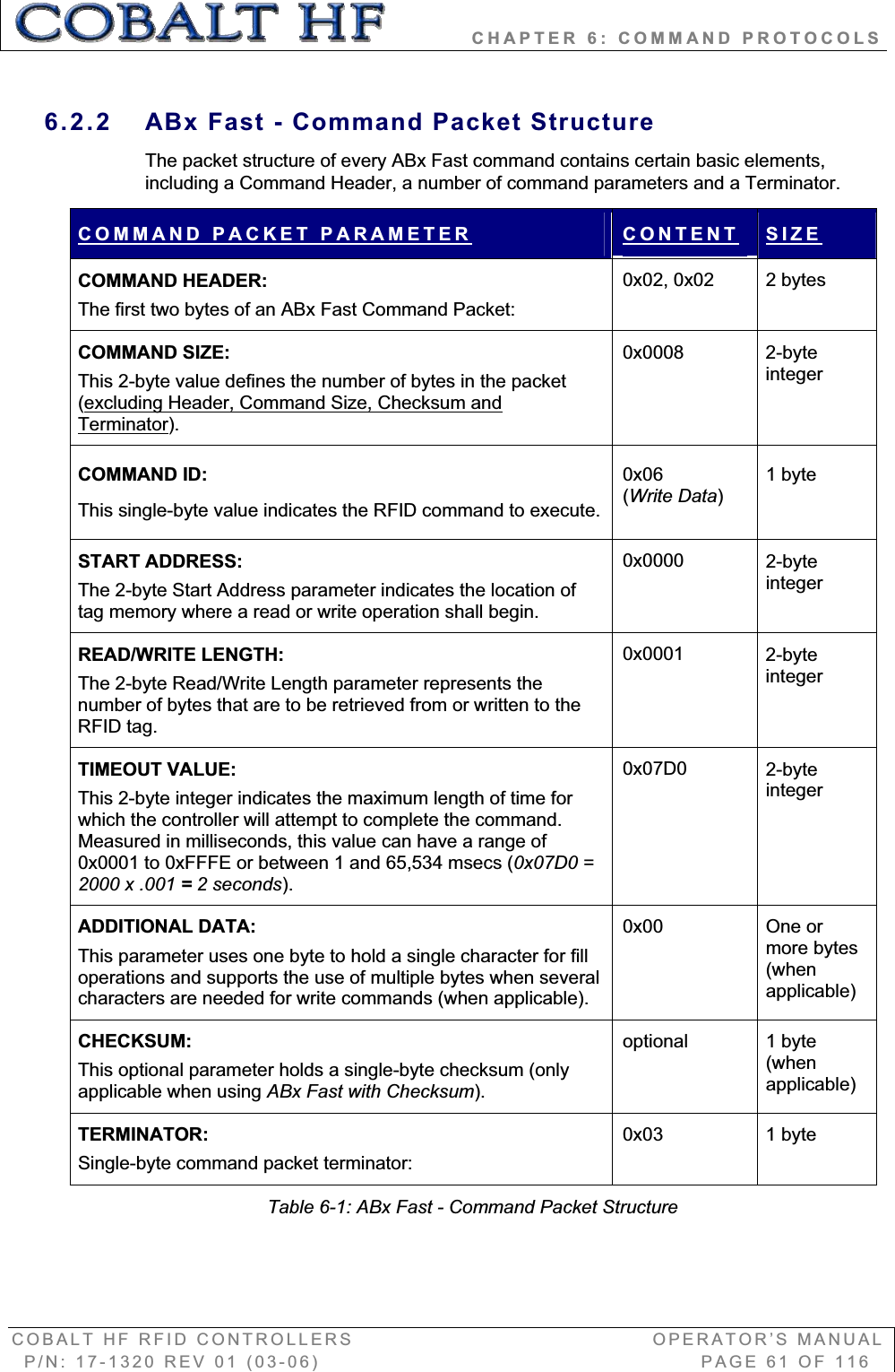
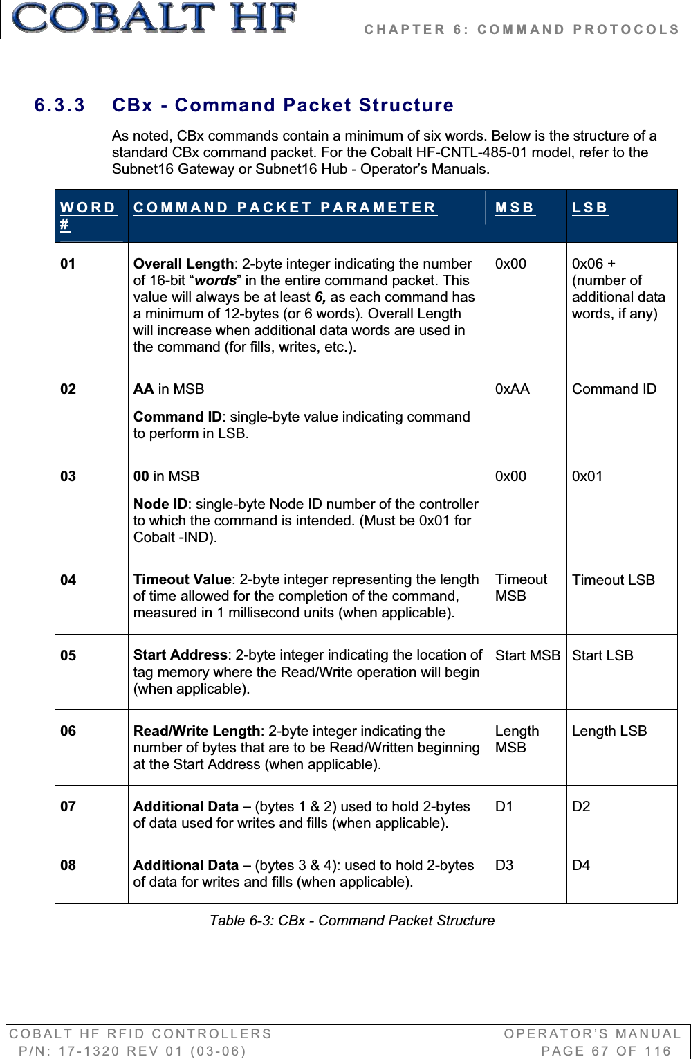
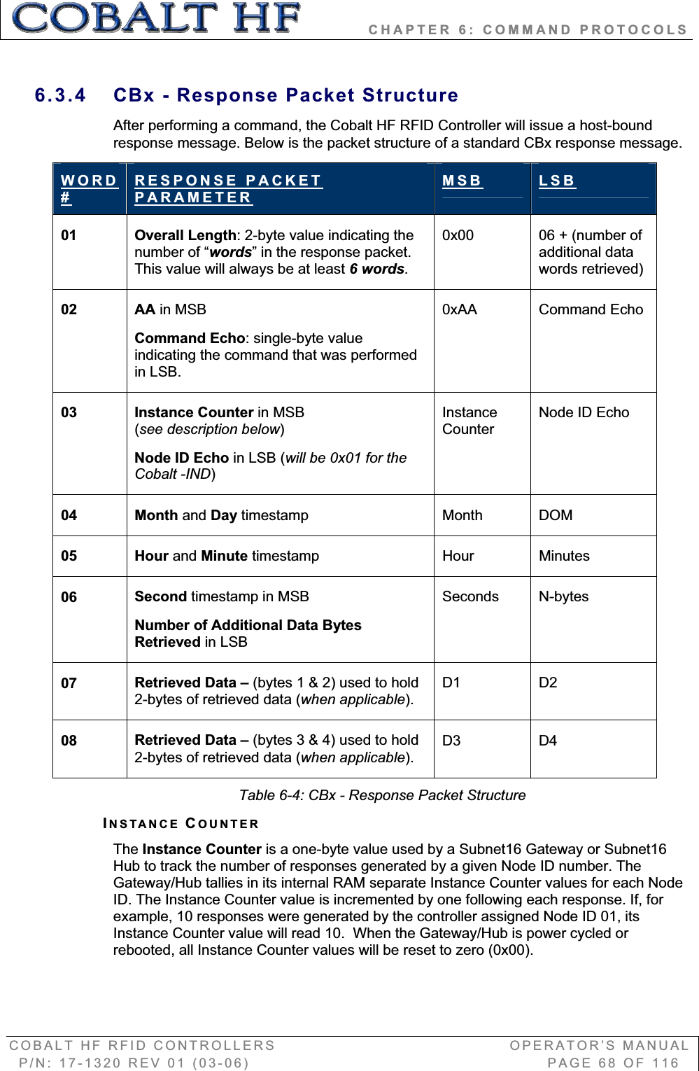
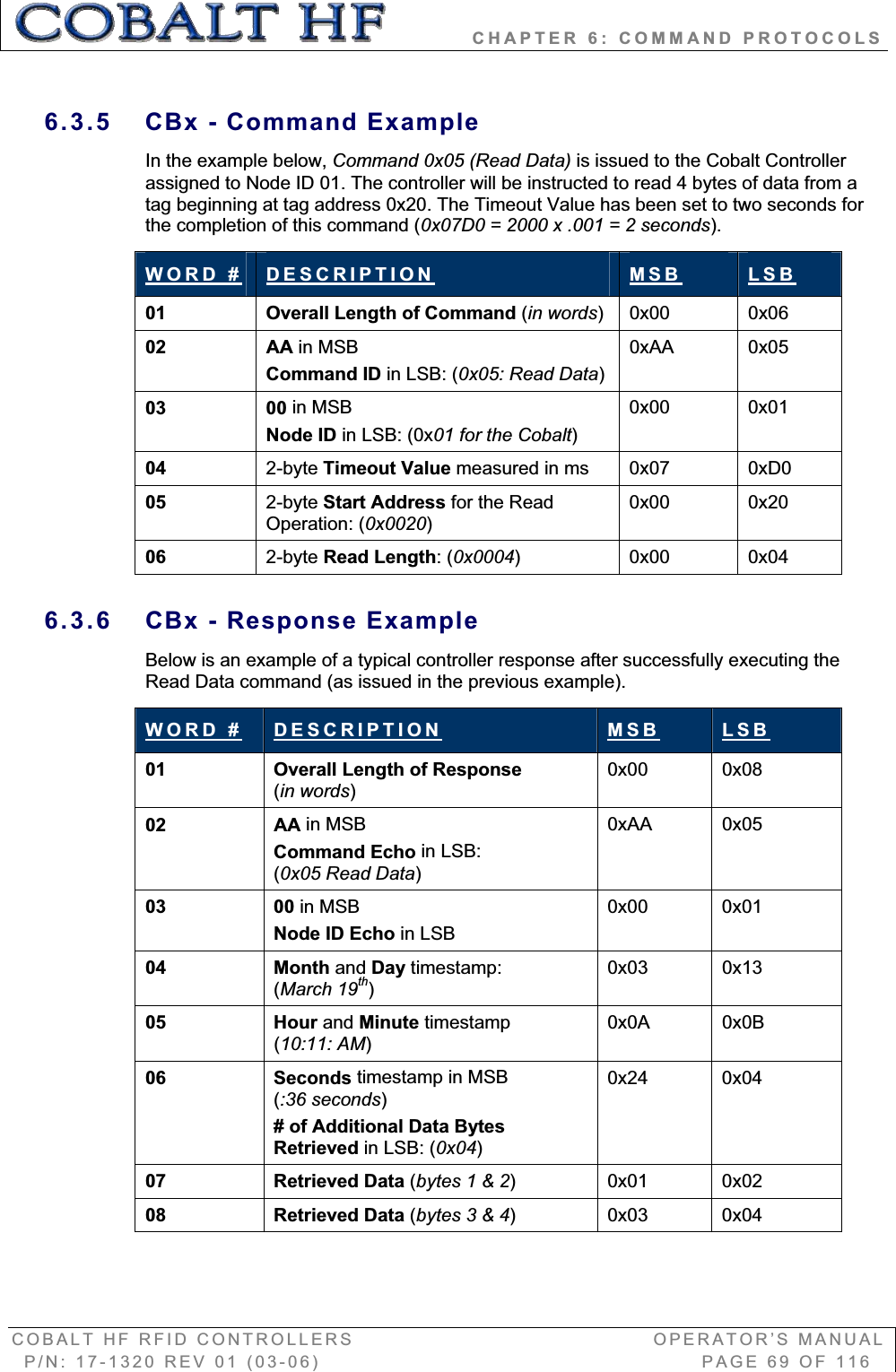
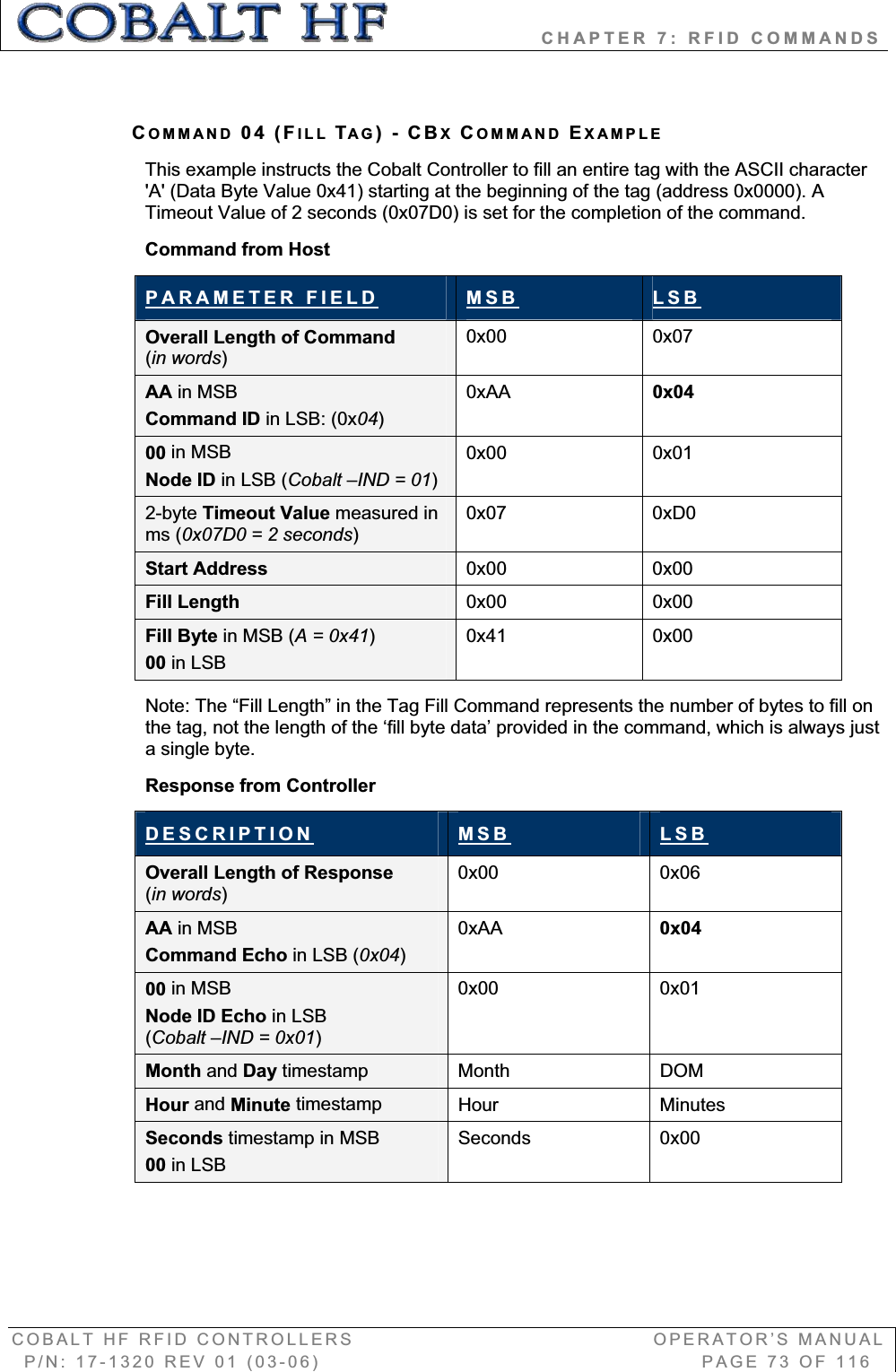
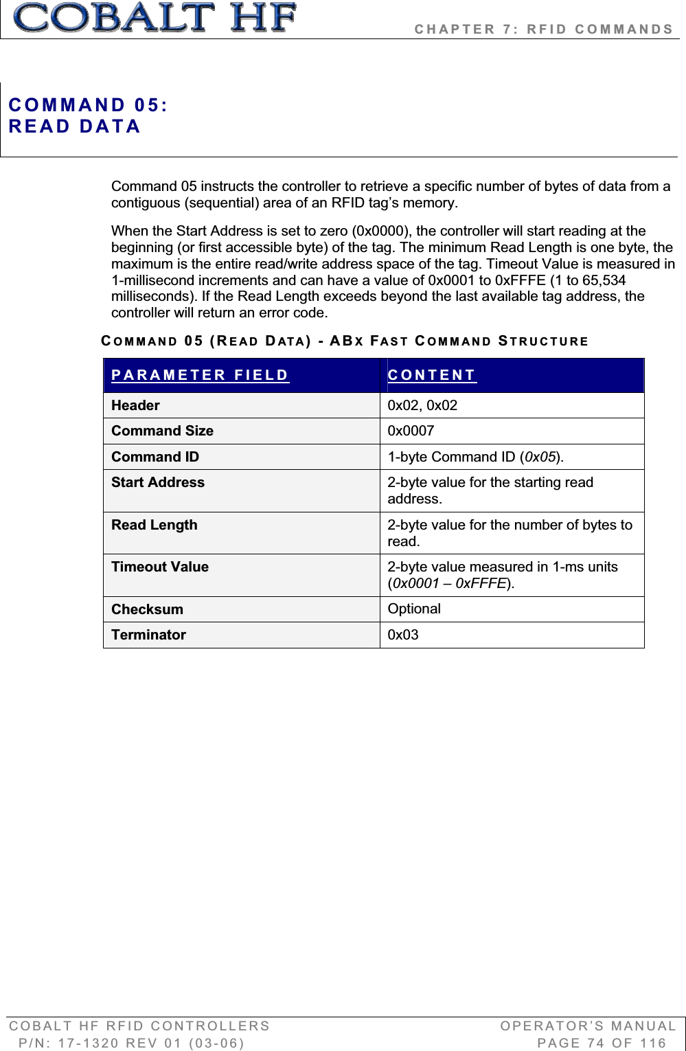
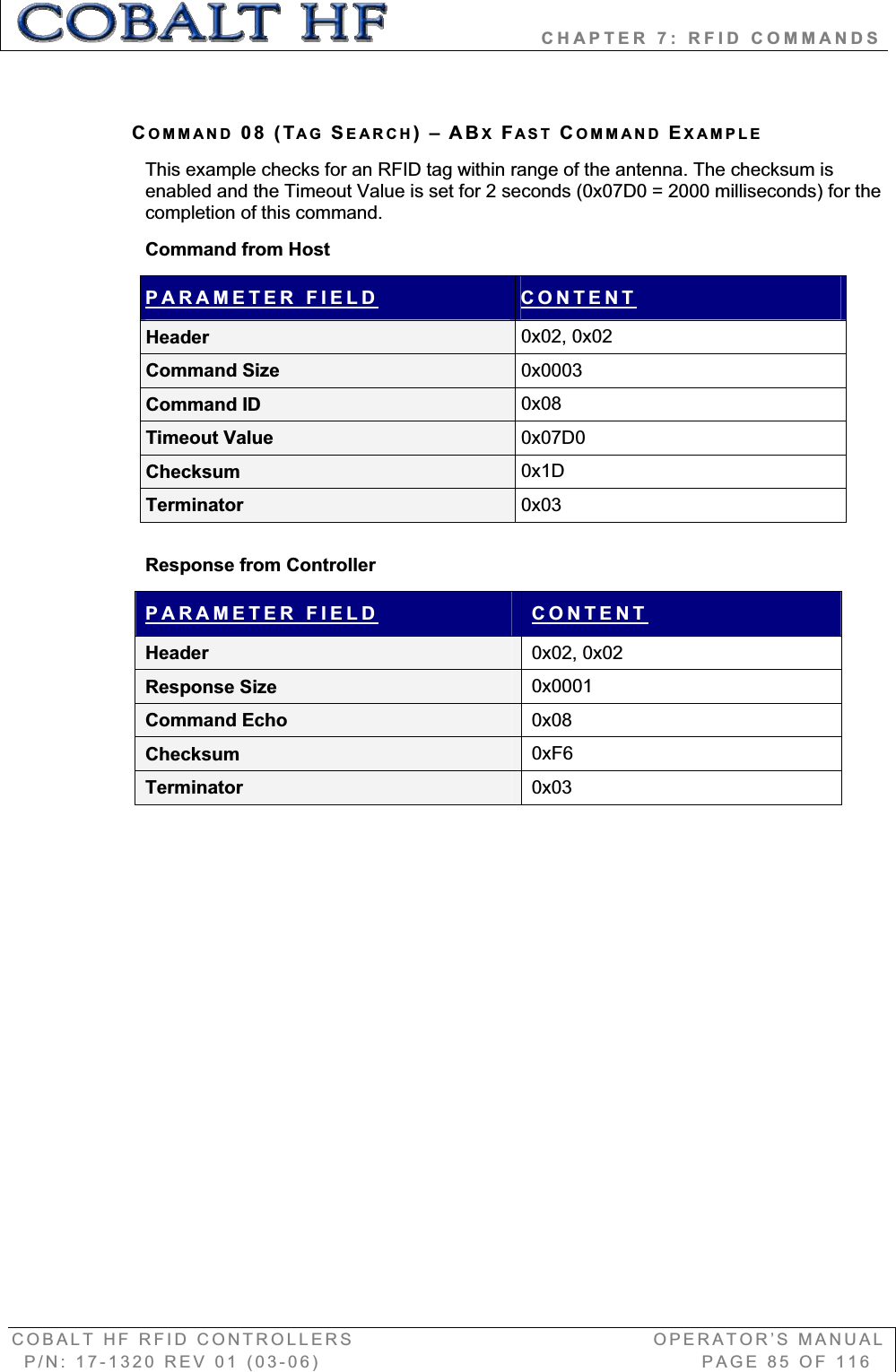
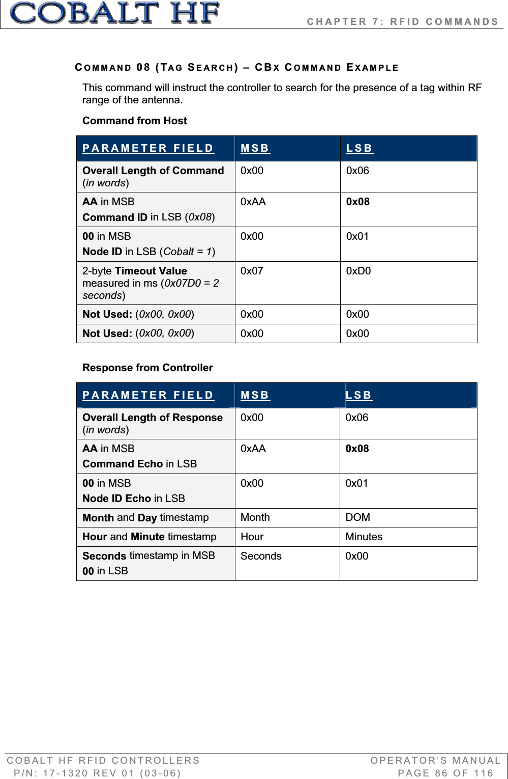
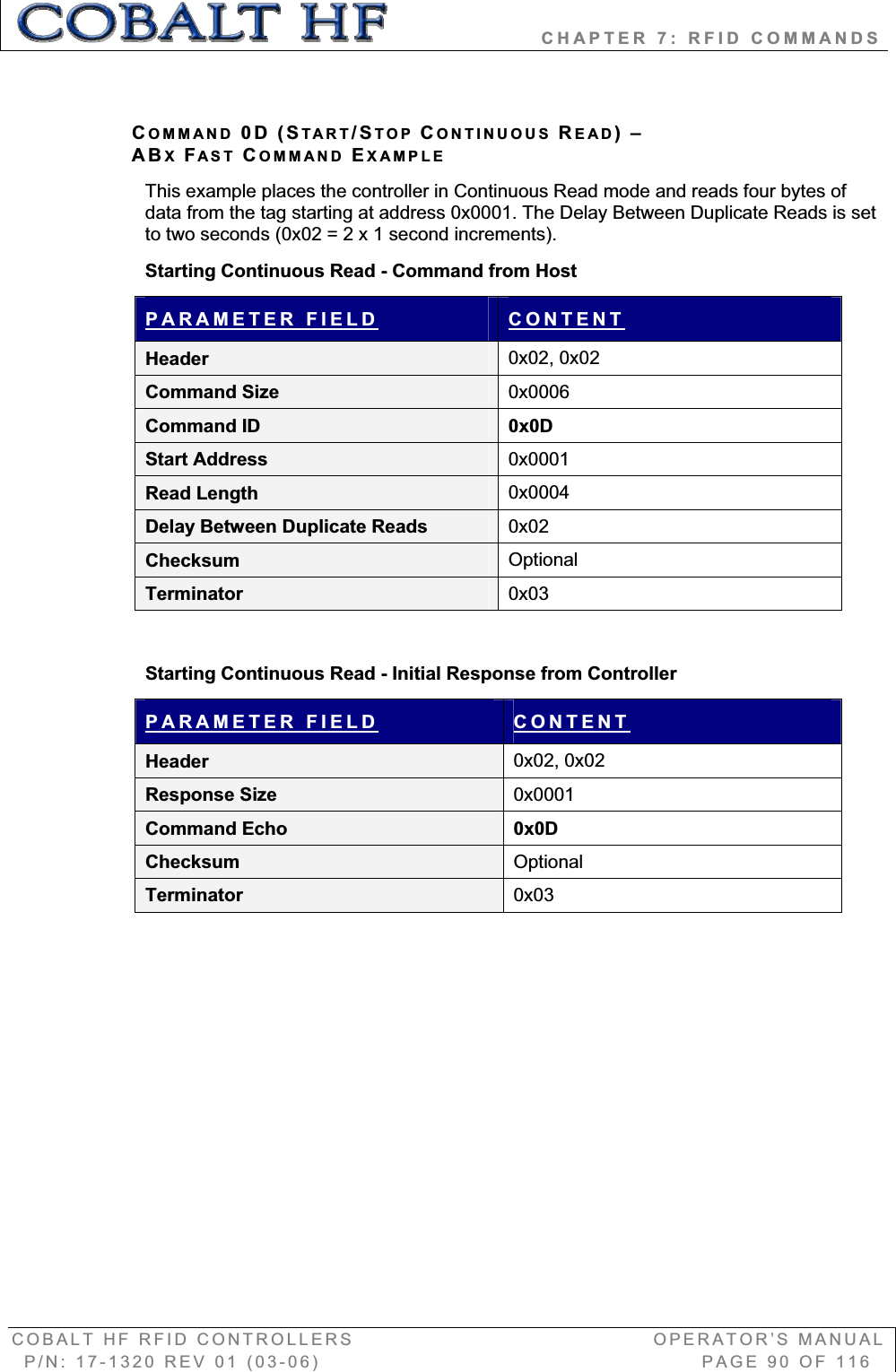
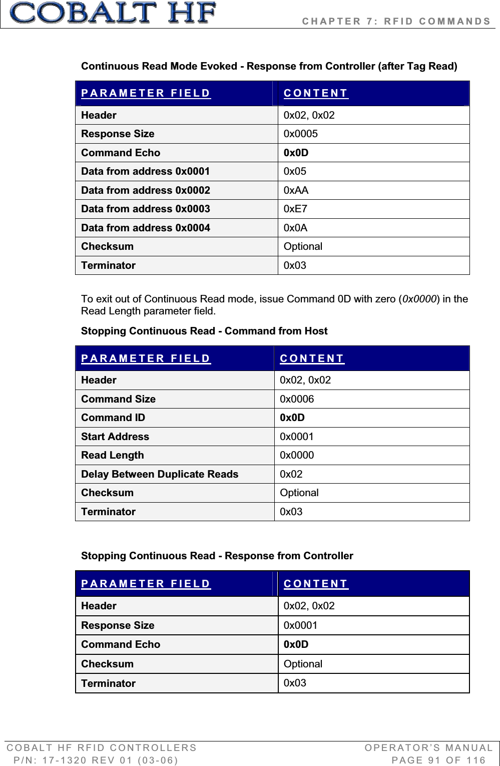
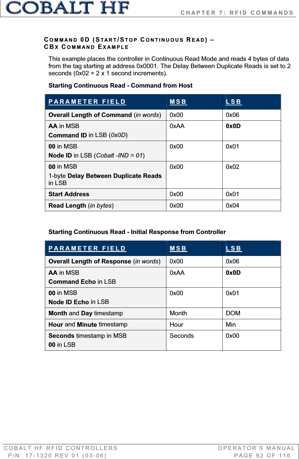
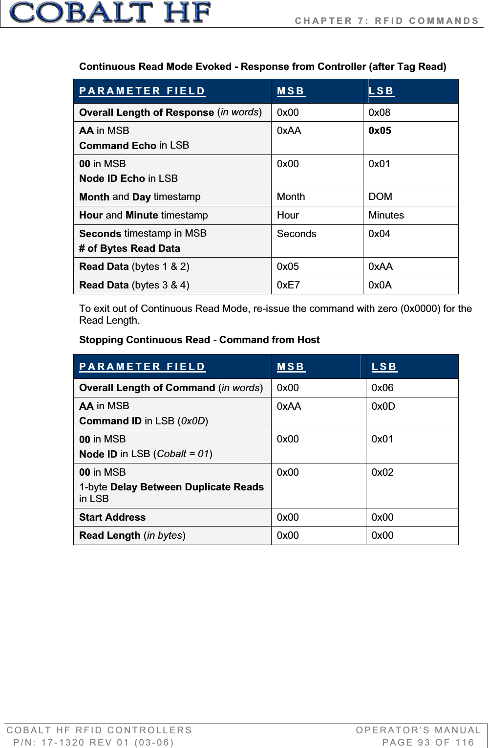
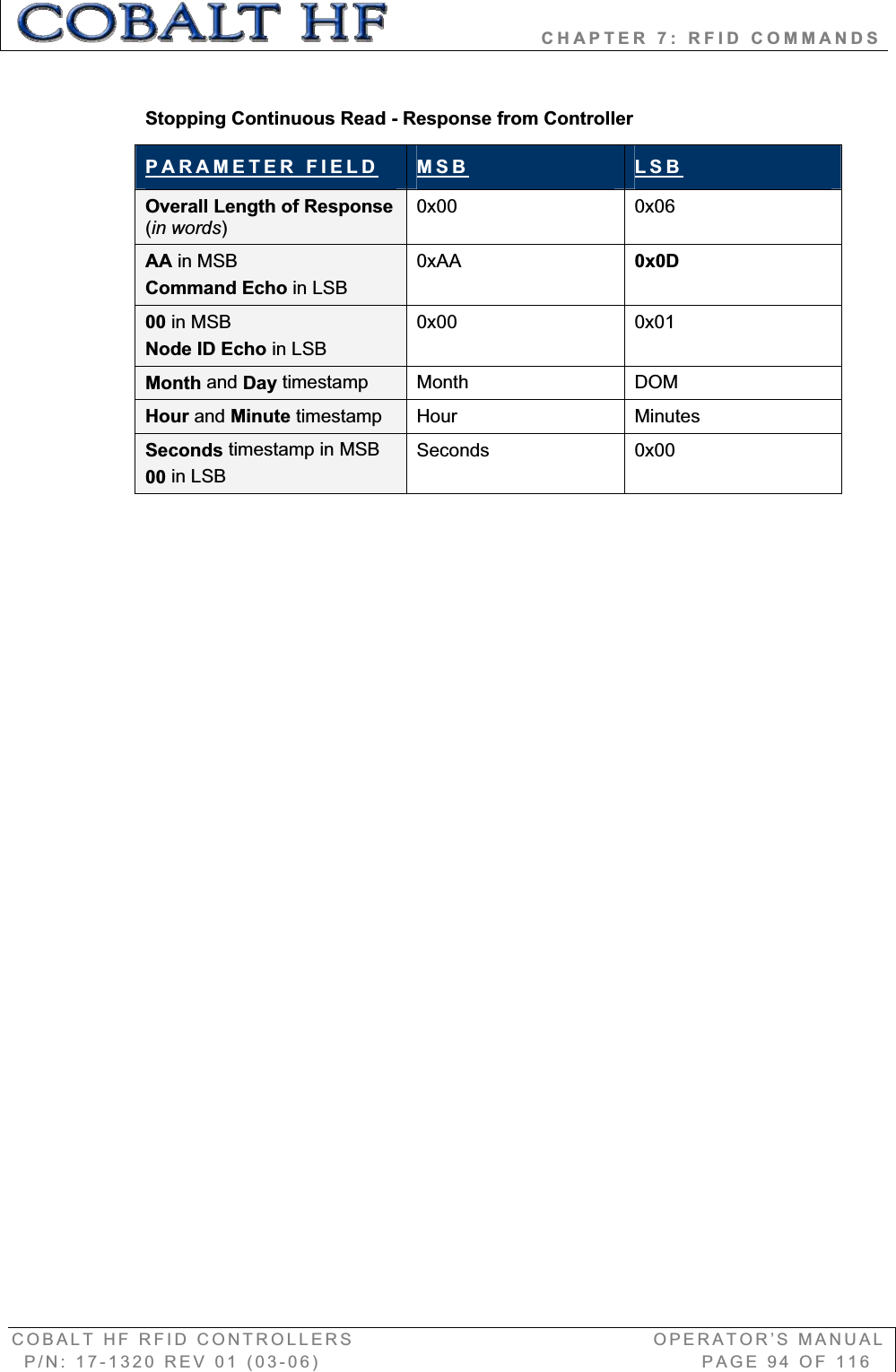
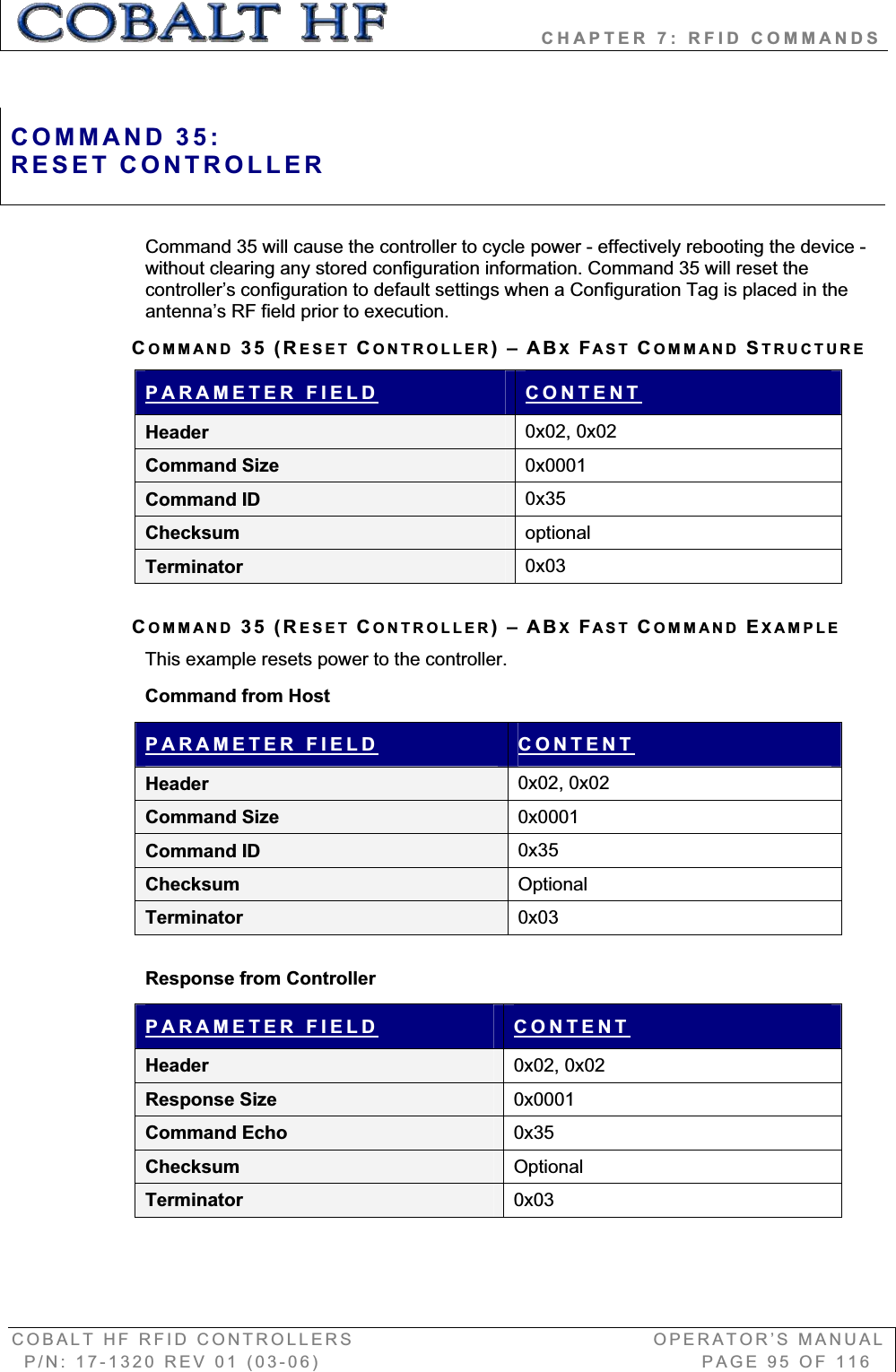
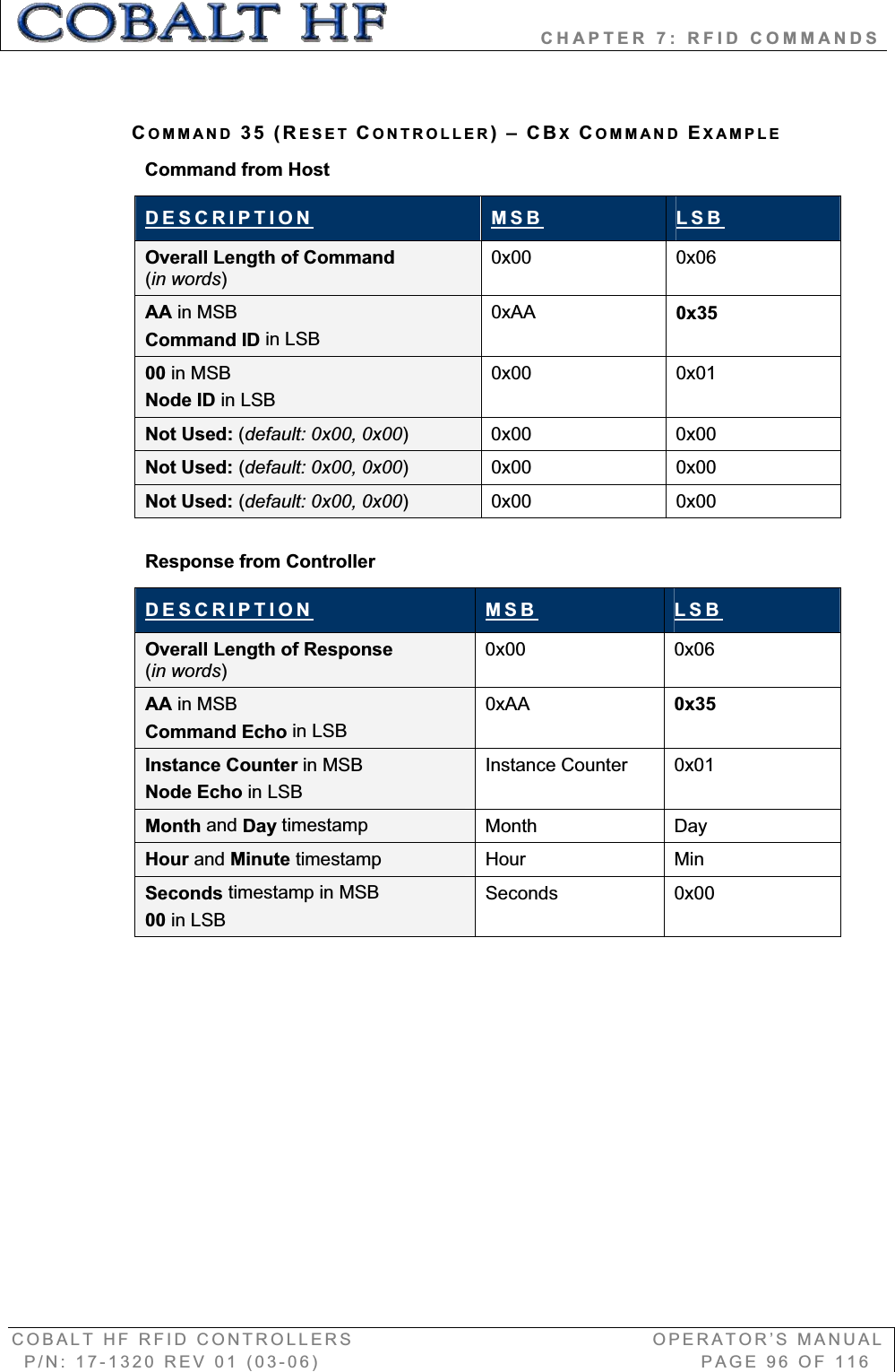
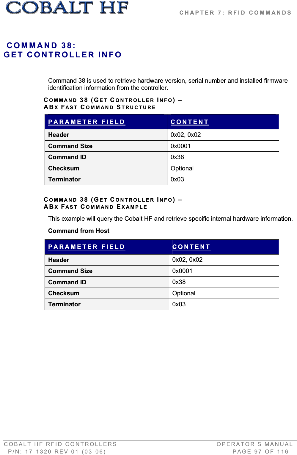
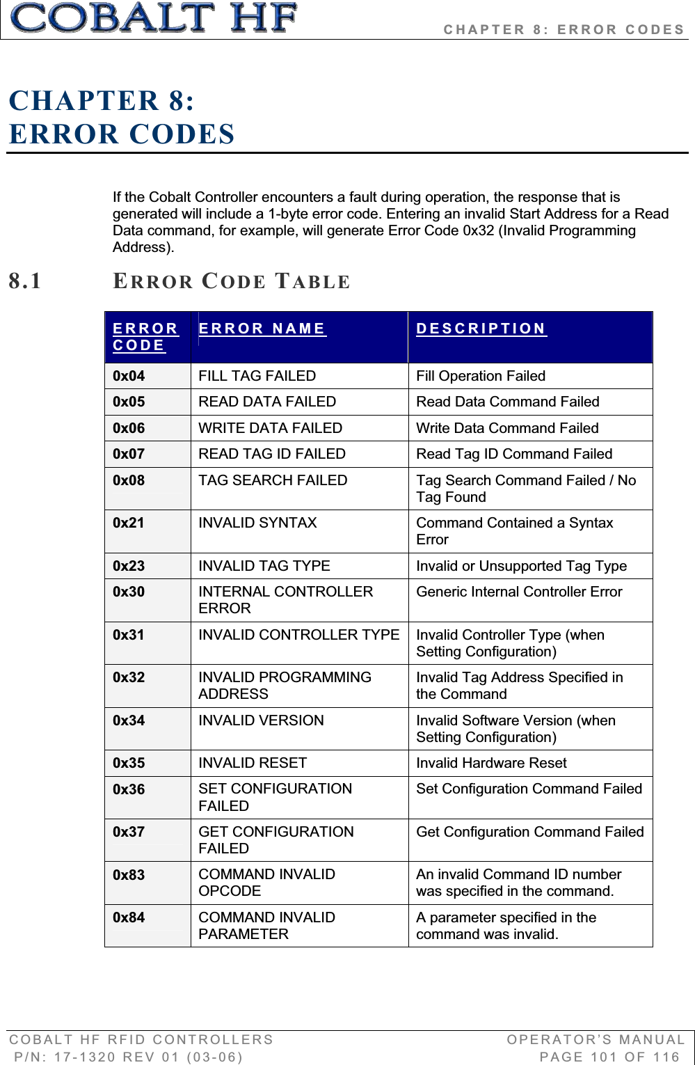
![CHAPTER 6: COMMAND PROTOCOLS COBALT HF RFID CONTROLLERS OPERATOR’S MANUAL P/N: 17-1320 REV 01 (03-06) PAGE 65 OF 116 CHECKSUM EXAMPLEThe following example depicts Command 0x05 (Read Data) using a checksum. COMMANDPARAMETERCONTENTS USED IN CHECKSUMHeader 0x02, 0x02 n/a Command Size 0x0007 0x00, 0x07 Command ID 0x05 0x05Start Address 0x0001 0x00, 0x01 Read Length 0x0004 0x00, 0x04 Timeout Value 0x07D0 0x07, 0xD0 Checksum 0x17 n/aTerminator 0x03 n/a Add the byte values from the Command Size, Command ID, Start Address, Read Length and Timeout Value parameters together and subtract from 0xFF. Resulting value will be the checksum. [0x07 + 0x05 + 0x01 + 0x04 + 0x07 + 0xD0] = 0xE8The checksum equation is: [0xFF – 0xE8] = 0x17Checksum = [0xFF – (sum of these fields)]](https://usermanual.wiki/Balluff/COBALT-01.Usr-Manual/User-Guide-708649-Page-15.png)