Balluff COBALT-01 RFID Reader / Writer (HF-CNTL-422-01) User Manual Cobalt HF Ops Manual17 1320 REV01
BALLUFF inc RFID Reader / Writer (HF-CNTL-422-01) Cobalt HF Ops Manual17 1320 REV01
Balluff >
Contents
- 1. User Manual
- 2. Usr Manual
Usr Manual
CHAPTER 5: RFID TAGS
COBALT HF RFID CONTROLLERS OPERATOR’S MANUAL
P/N: 17-1320 REV 01 (03-06) PAGE 51 OF 116
CHAPTER 5:
RFID TAGS
RFID tags, which are also referred to as transponders, smart labels, or
inlays, come in a variety of sizes, memory capacities, read ranges,
frequencies, temperature survivability ranges and physical
embodiments.
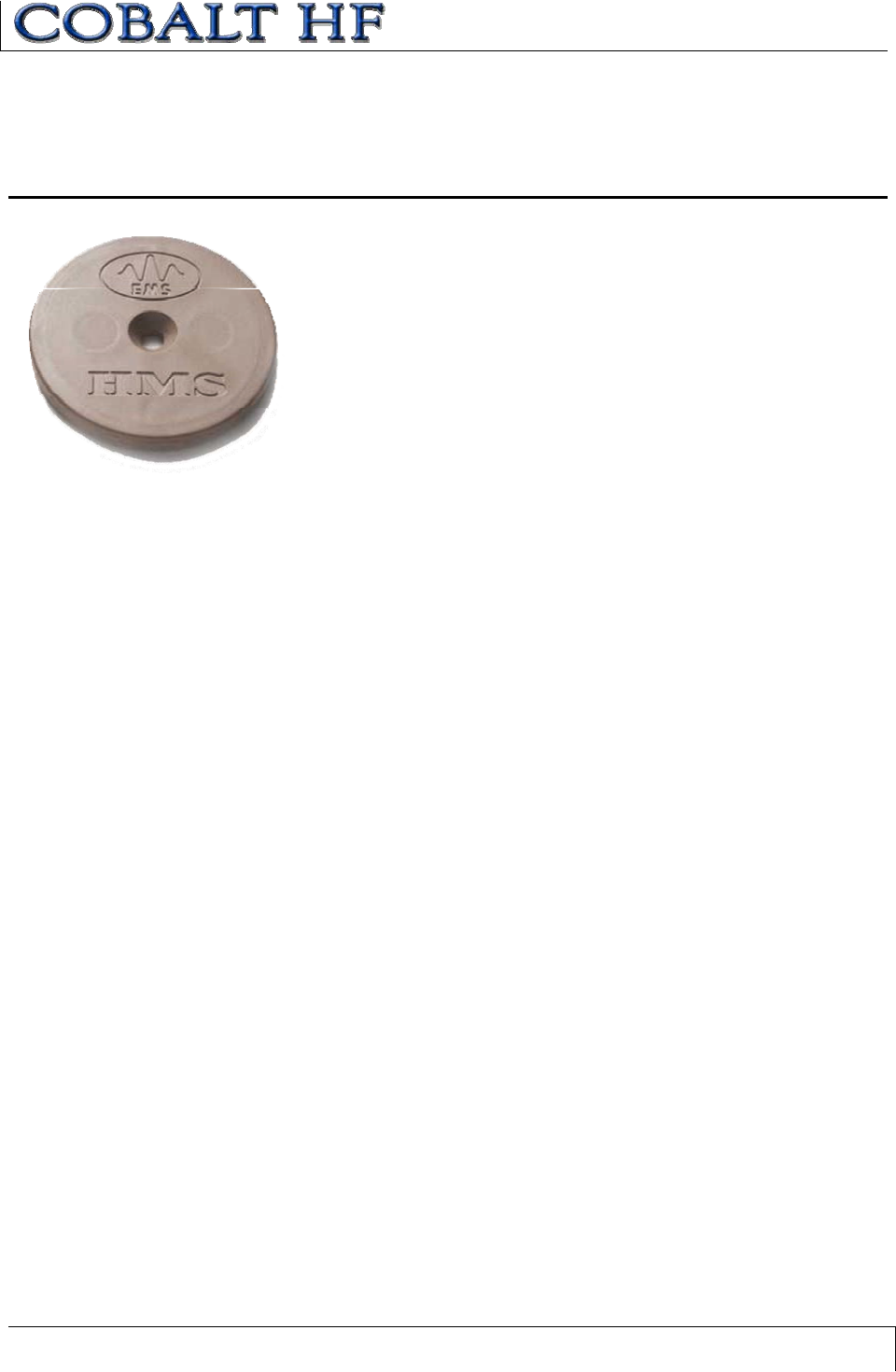
Escort Memory Systems offers many different RFID tag models. Cobalt
Controllers are capable of reading all Escort Memory Systems’ HMS
and LRP series RFID tags as well most of those produced by other
manufacturers. Our patented tags can be read through obstructions
such as water, wood, plastic and more. Our specialty high-temperature
(HT) models are capable of surviving temperatures of 415° F.
5.1 RFID STANDARDS
It is important to note that not all 13.56MHz RFID tags are compatible with Cobalt
Controllers and even tags that are said to be compliant with ISO15693 or ISO14443
standards may not actually be compatible with RFID controllers adhering to the same
standards. This is partially due to the fact that these ISO standards are so new that they
leave many features open to the discretion and interpretation of the RFID equipment
manufacturer to implement or define. When using another manufacturer’s tags, ensure
compatibility of those tags with your RFID system provider.
5.1.1 ISO 14443A/B
RFID integrated circuits (ICs) designed to meet ISO 14443A and/or ISO 14443B
standards were originally intended to be embedded in secure smart cards such as credit
cards, passports, bus passes, ski lift tickets, etc. For this reason, there are many security
authentication measures implemented within the air protocol between the RFID controller
and the tag.
ISO 14443A/B compliant tags and controllers incorporate security authentication through
the exchanging of software “keys.” The RFID controller and the tag must use the same
security keys to authenticate communication before the transfer of data will begin. The
Cobalt Controller’s operating system manages these security features, making their
existence transparent to the user. However, it is important to understand the implications
associated with ISO 14443 when using another manufacturer’s RFID tags. Because of
these security “features,” an ISO 14443 tag made by one manufacturer may not
necessarily be readable by a Cobalt Controller and, likewise, an Escort Memory Systems
ISO 14443 compliant tag might not be readable by another manufacturer’s RFID
controller. The Cobalt Controllers support Escort Memory Systems’ security keys for use
on Philips mifare ISO 14443A tags.
Escort Memory Systems was one of the first companies to adopt ISO 14443 standards
and has incorporated much of the technology into our products designed for industrial
automation applications. But because most industrial environments do not require the
same level of security that monetary or passport applications necessitate, some features
have not been implemented in the Cobalt HF product line.

CHAPTER 5: RFID TAGS
COBALT HF RFID CONTROLLERS OPERATOR’S MANUAL
P/N: 17-1320 REV 01 (03-06) PAGE 52 OF 116
5.1.2 ISO 15693
ISO 15693 was established at a time when the RFID industry identified that the lack of
standards was preventing the market from growing. Philips Semiconductor and Texas
Instruments were, at that time, the major manufacturers producing RFID ICs for the
Industrial, Scientific, and Medical (ISM) frequency of 13.56MHz. However, each had their
own unique protocol and modulation algorithm. Philips Semiconductor’s I-CODE® and
Texas Instruments Tag-it® product lines were eventually standardized on the mutually
compatible ISO 15693 standards. After the decision was made to standardize, the door
was opened for other silicon manufacturers to enter the RFID business, many of which
have since contributed to other RFID ISO definitions. This healthy competition has led to
rapid growth in the RFID industry and has pushed the development of new standards,
such as ISO 18000 for Electronic Product Code (EPC) applications.
5.1.3 ISO 18000-3.1
The ISO 18000 standard has not been implemented in the Cobalt HF product line at the
time of publication of this manual. It is a planned product enhancement for future
releases. The emerging ISO 18000 Standard will provide enhanced support for EPC and
Unique Identification (UID) tag applications.
CHAPTER 5: RFID TAGS
COBALT HF RFID CONTROLLERS OPERATOR’S MANUAL
P/N: 17-1320 REV 01 (03-06) PAGE 53 OF 116
5.2 RFID TAG COMPATIBILITY
The following RFID tags are compatible with the Cobalt HF Controller:
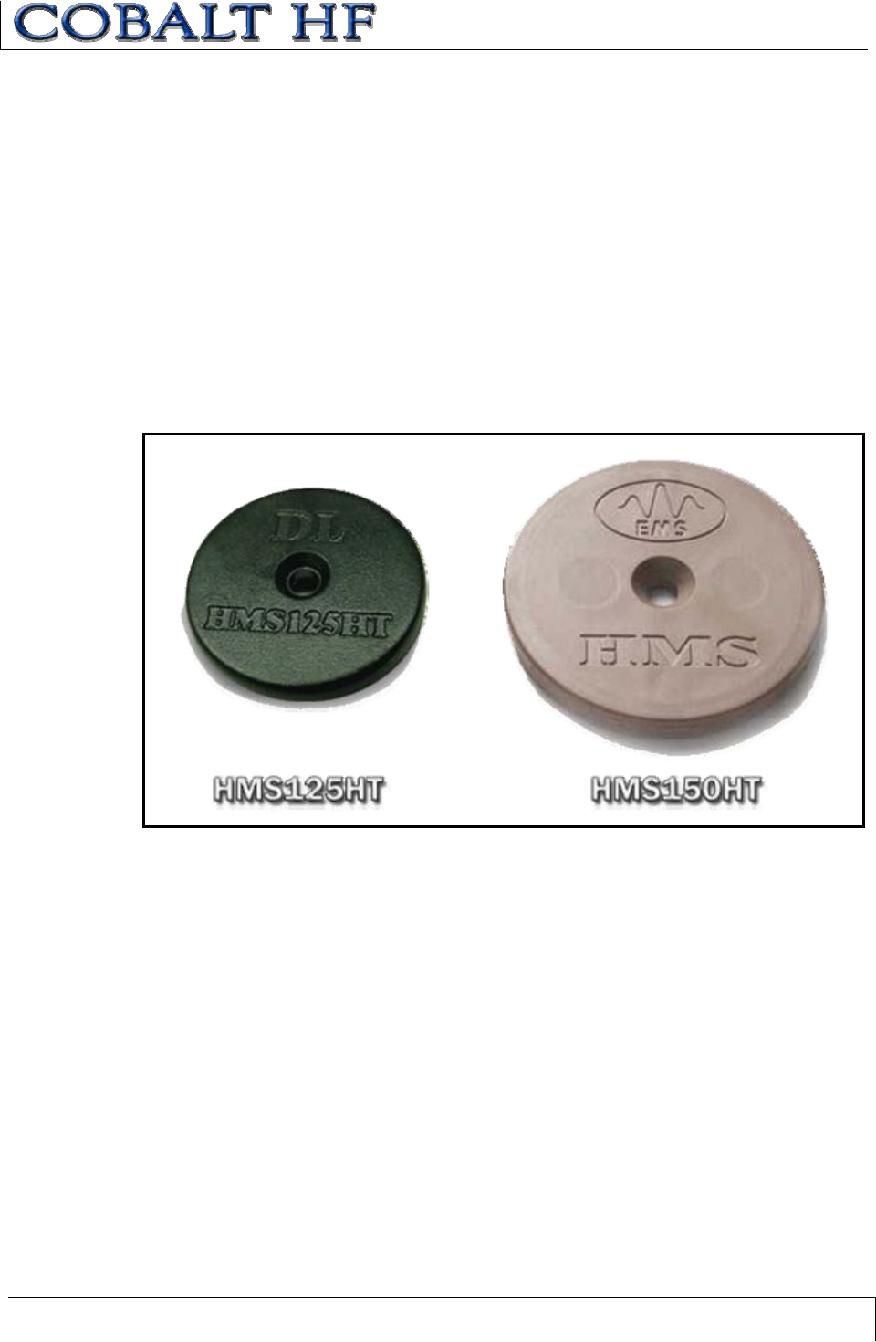
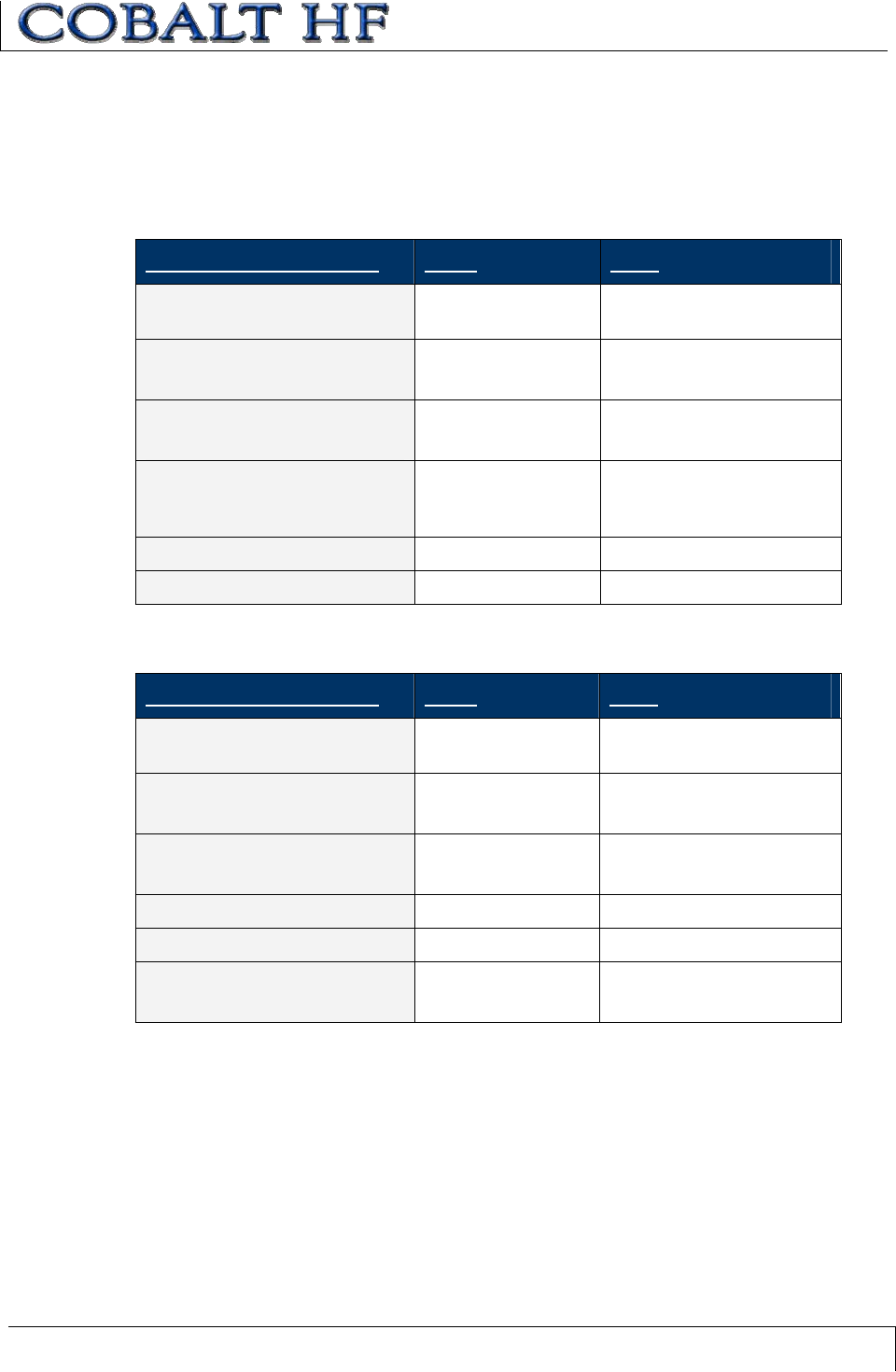
5.2.1 HMS Series RFID Tags
Integrated Circuits (ICs) used in Escort Memory Systems’ HMS-Series RFID tags include:
xPhilips mifare Classic, 1 kilobyte (KB) + 32-bit Tag ID (ISO 14443A). One KB is
the total memory in the IC. Of this memory, 736 bytes are available for user data.
xPhilips mifare Classic, 4 KB + 32-bit Tag ID (ISO 14443A). Four KB is the total
memory in the IC. Of this memory, 3,440 bytes are available for user data.
Figure 5-1: HMS125HT and HMS150HT RFID Tags
CHAPTER 5: RFID TAGS
COBALT HF RFID CONTROLLERS OPERATOR’S MANUAL
P/N: 17-1320 REV 01 (03-06) PAGE 54 OF 116
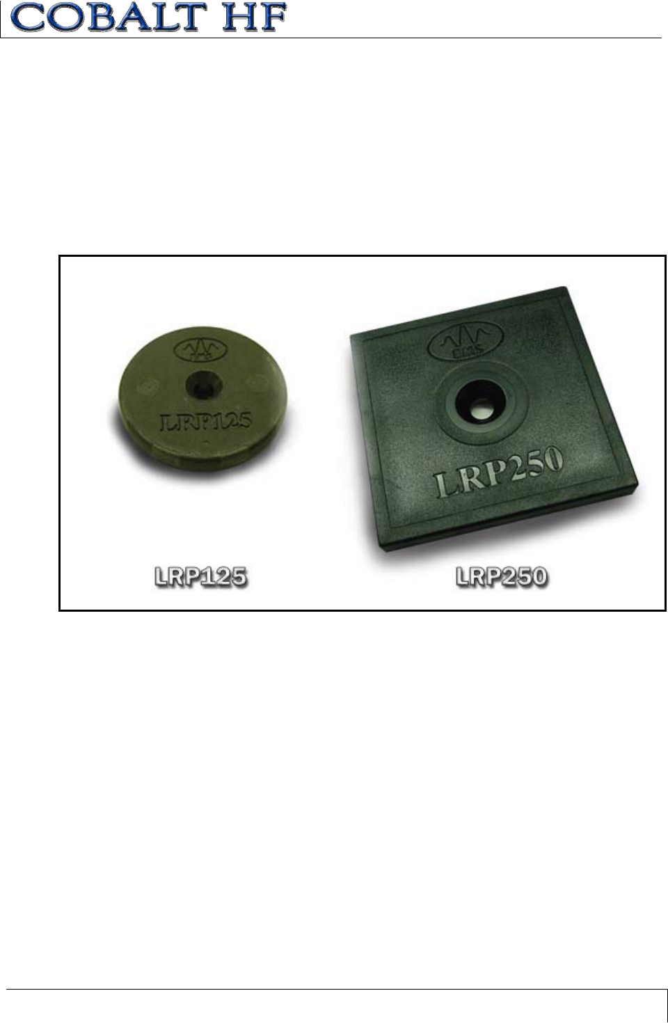
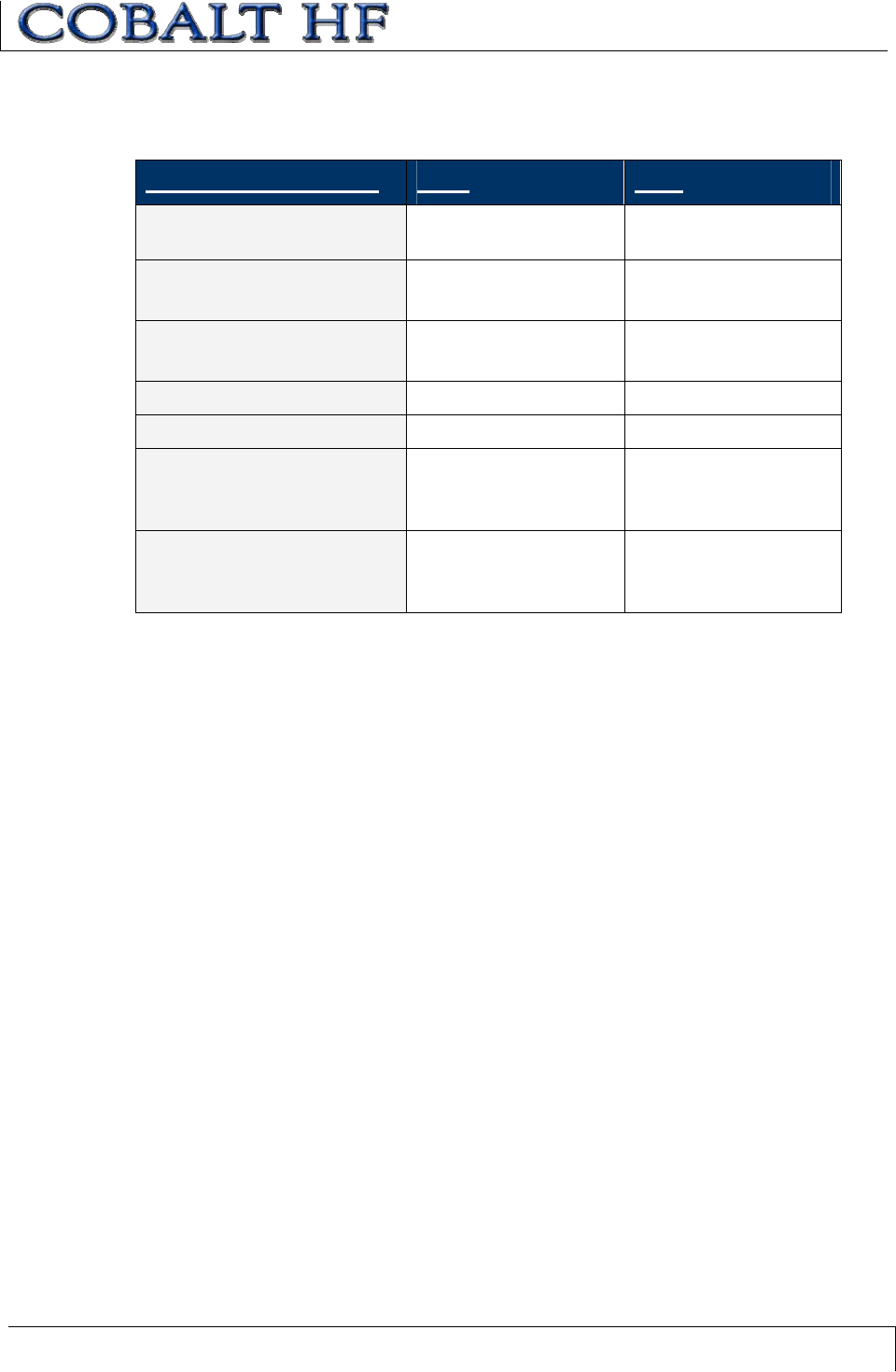
5.2.2 LRP Series RFID Tags
ICs used in Escort Memory Systems’ LRP-Series RFID tags include:
xPhilips I•CODE 1, 48-byte + 64-bit Tag ID
xPhilips I•CODE SLi, 112-byte + 64-bit Tag ID (ISO 15693)
xTexas Instruments Tag-it, 32-byte + 64-bit Tag ID (ISO 15693)
xInfineon My-D Vicinity, 1kb + 64-bit Tag ID (ISO 15693)
Figure 5-2: LRP125 and LRP250 RFID Tags
CHAPTER 5: RFID TAGS
COBALT HF RFID CONTROLLERS OPERATOR’S MANUAL
P/N: 17-1320 REV 01 (03-06) PAGE 55 OF 116
5.3 RFID TAG PERFORMANCE
Many factors can affect the performance between the controller’s antenna and the tag’s
antenna. These include, but are not limited to: the tag integrated circuit (IC), the antenna
coil design, the antenna conductor material, the antenna coil substrate, the bonding
method between tag IC antenna coil, and the embodiment material.
Additionally, the mounting environment of the tag and controller can hinder performance
due to other materials affecting the tuning of either antenna. Escort Memory Systems has
undergone extensive testing to produce tags that obtain optimum performance with our
RFID controllers. In most cases, optimal range will be obtained when mounting the tag
and controller antenna in locations free from the influence of metals, ESD and EMI
emitting devices.
5.4 RFID TAG EMBODIMENTS
RFID tags come in a variety of sizes and packages. The most common and cost effective
tag embodiment is the RFID label.
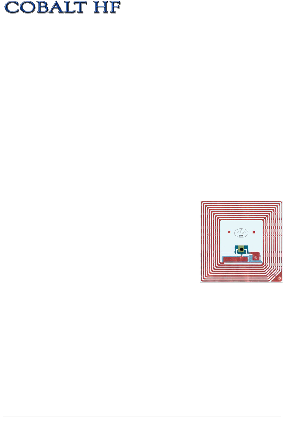
5.4.1 RFID Labels
RFID Labels (inlays or inlets) are the lowest cost RFID tag solution and are typically used
in an open system in which the tag leaves the facility attached to a product or is
destroyed at the end of the process.
An inlay is a substrate (made of polyester or Mylar) with a
printed, screened or etched antenna coil. Sometimes the
coil consists of a wire that is laid down onto the substrate
and is bonded to it with heat. Typically, the RFID IC is
attached by means of flip-chip technology and the
electrical connections are made by means of conductive
epoxies.
RFID inlays are usually applied to sticker backed paper to
create label tags which are manufactured in high volumes
on roll-to-roll production equipment. Inlays can be
laminated an used in smart credit cards, providing a low
cost RFID tag with some protection from impact damage.
The materials and procedures used to manufacture an RFID label’s antenna coil are
critically important. Low cost processes (such as printing or screening) produce low
quality antenna coils which can exhibit poor conductivity and cracking when flexed.
Labels with copper wire wound coils are generally considered efficient conductors of RF
energy and can usually survive considerable flexing, but are often more expensive due to
more involved production processes.
RFID labels with etched copper antenna coils have been found to be the most reliable,
semi-low cost tag solution. Etched inlay antenna coils are usually of consistent quality
and can survive a great deal of flexing and bending. However, because etching is
inherently a subtractive process, the cost per tag increases in part due to copper and
other metals discarded during the fabrication process.
As RFID label manufacturing technology advances, there have been several new
developments made in the areas of high volume, low cost, antenna coil manufacturing.
CHAPTER 5: RFID TAGS
COBALT HF RFID CONTROLLERS OPERATOR’S MANUAL
P/N: 17-1320 REV 01 (03-06) PAGE 56 OF 116
One area, in particular, that has shown recent promise is the process of electroplating
printed or screened antenna coils with an additional layer of copper to improve durability
and conductivity.
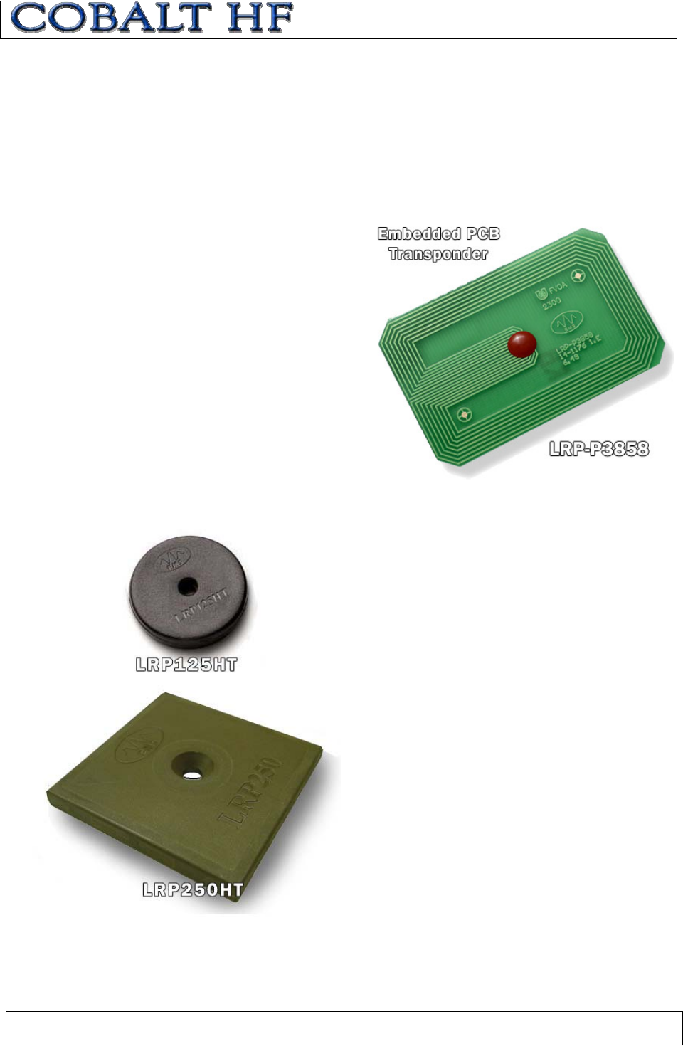
5.4.2 Printed Circuit Board RFID Tags
RFID tags that incorporate Printed Circuit Board (PCB) technology are designed for
encasement inside totes, pallets, or products that can provide the protection normally
associated with injection-molded
enclosures.
These tags are made primarily from
etched copper PCB materials (FR-4,
for example) and are die bonded by
means of high quality wire bonding.
This procedure ensures reliable
electrical connections that are
superior to flip-chip assembly
methods. The RFID tag’s integrated
circuit is then encapsulated in epoxy
to protect it and the electrical
connections.
5.4.3 Molded RFID Tags
Molded tags, which are PCB tags
that have been protected with a durable resin overmolding, are the most rugged and
reliable type of tag offered by Escort Memory Systems. These tags are designed for
closed loop applications where the tag is reused;
thereby the cost of the tag can be amortized over
the life of the production line.
Typically, molded tags will be mounted to a pallet
or carrier which transports the product throughout
the production process. Some of the applications
for these tags include, but are not limited to:
embedding the tag into concrete floors for location
identification by forklifts and automatically guided
vehicles (AGVs), shelf identification for storage
and retrieval systems, and tool identification.
High temperature (HT) tags, using patented
processes and specialized materials, allow tags to
survive elevated temperatures, such as those
found in automotive paint and plating applications.
Escort Memory Systems offers a wide variety of
molded tags that have been developed over the
years for real world applications.

CHAPTER 5: RFID TAGS
COBALT HF RFID CONTROLLERS OPERATOR’S MANUAL
P/N: 17-1320 REV 01 (03-06) PAGE 57 OF 116
5.5 TAG MEMORY
Tag memory addressing begins at address 00 (0x0000), with the highest addressable
memory location equal to one less than the total number of bytes in the tag. Each
address is equal to one byte (8-bits), where the byte is the smallest addressable unit of
data. So for example, writing 8-bytes to a tag beginning at address 00 will actually fill
addresses 00 through 07 with 64-bits of data in all.
Depending on the manufacturer, RFID labels, molded tags and embedded PCBs can
have differing memory storage capacities and organization. Tag memory is grouped into
blocks of bytes that can vary in structure from manufacturer to manufacturer. Even when
compliant to ISO standards, byte memory addressing can differ from one manufacturer to
another. For example, tag memory can be organized in blocks of 4 or 8 bytes, depending
on the RFID IC. Additionally, all bytes may not be available for data storage as some
bytes may be used for security and access conditions. For more information regarding a
specific RFID tag’s memory allocation, please refer to IC manufacturer’s published
datasheet or Website.
Escort Memory Systems has taken great care to simplify tag memory addressing. The
mapping from logical address to physical address is handled by the Cobalt Controller’s
operating system. Users only need to indicate the starting address location on the tag
and the number of bytes to be read or written.
Is it a Bit or a Byte?
Customers need to understand that there are some RFID tag manufacturers that
measure and specify their tag memory size by the total number of bits, as this method
generates a much larger (8X) overall number. Escort Memory Systems, on the other
hand, prefers to specify total tag memory size in terms of bytes (rather than in bits), as
this method more closely reflects how data is stored and retrieved from a tag and is
typically what users really want to know.
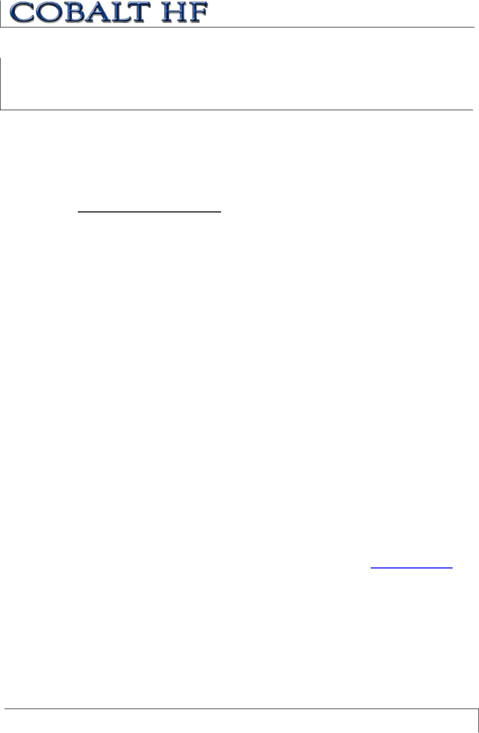
5.5.1 Mapping Tag Memory
Creating an RFID Tag Memory Map
Creating a Tag Memory Map is much like creating a spreadsheet that outlines the actual
data you plan to capture as well as the specific tag memory locations in which you wish
to store said data. Tag Memory maps should be carefully planned, simple and
straightforward. It is advisable to allow additional memory space than is initially required
as inevitably a need will arise to store more data.
In the example below, 90-bytes of a 112-byte tag have been allocated to areas of the
Memory Map (leaving roughly 20% free for future uses). Because a short paragraph of
alphanumeric characters could quickly use all 90 bytes, creating an efficient mapping
scheme which utilizes all 720-bits (out of the 90-bytes allocated) will provide a better use
of tag space.
CHAPTER 5: RFID TAGS
COBALT HF RFID CONTROLLERS OPERATOR’S MANUAL
P/N: 17-1320 REV 01 (03-06) PAGE 58 OF 116
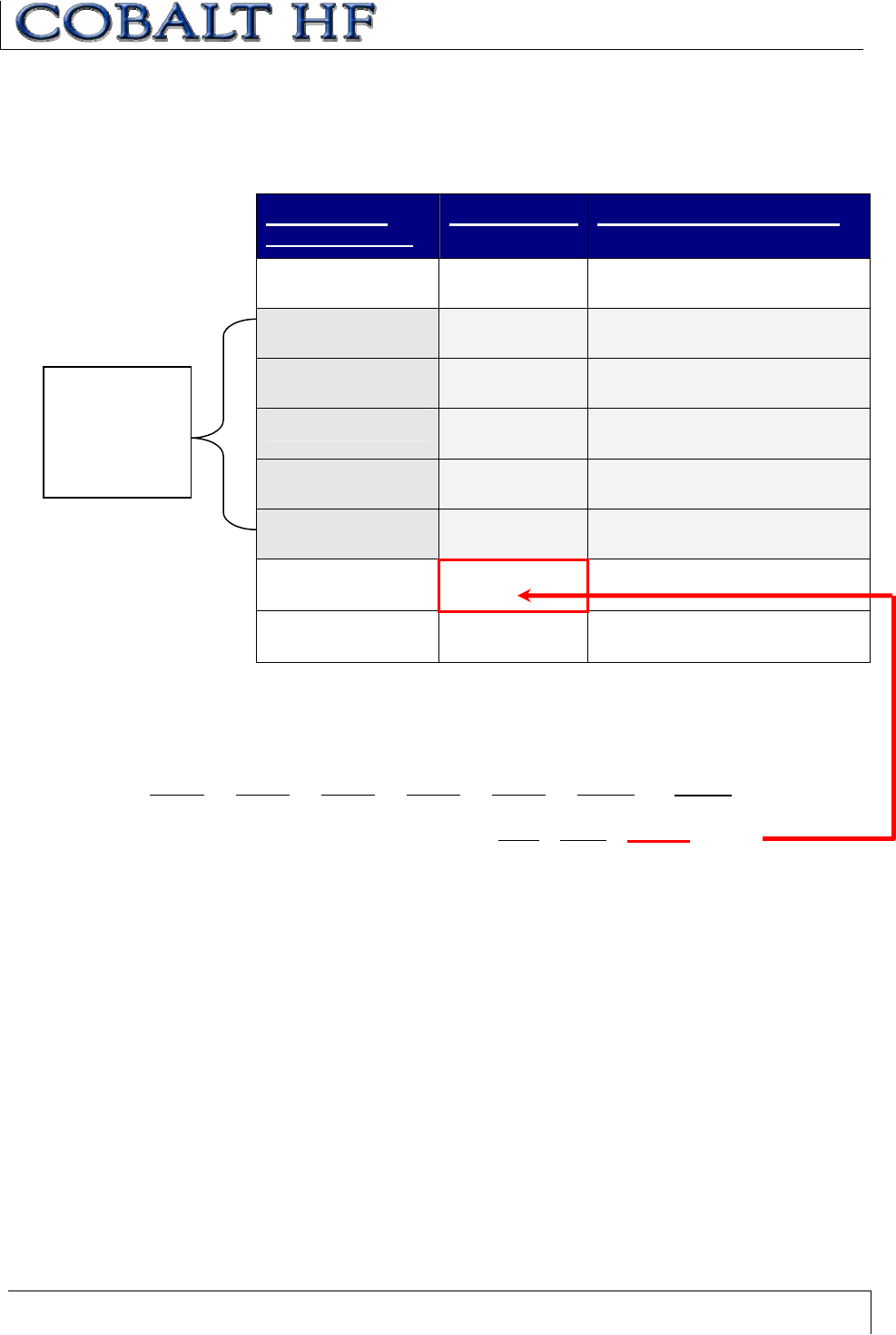
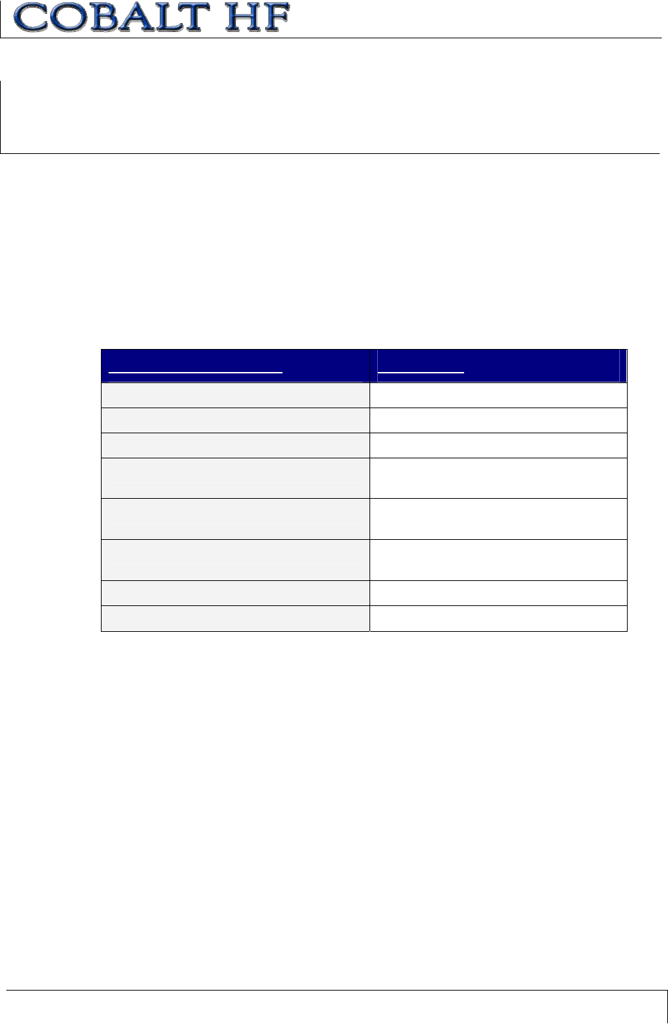
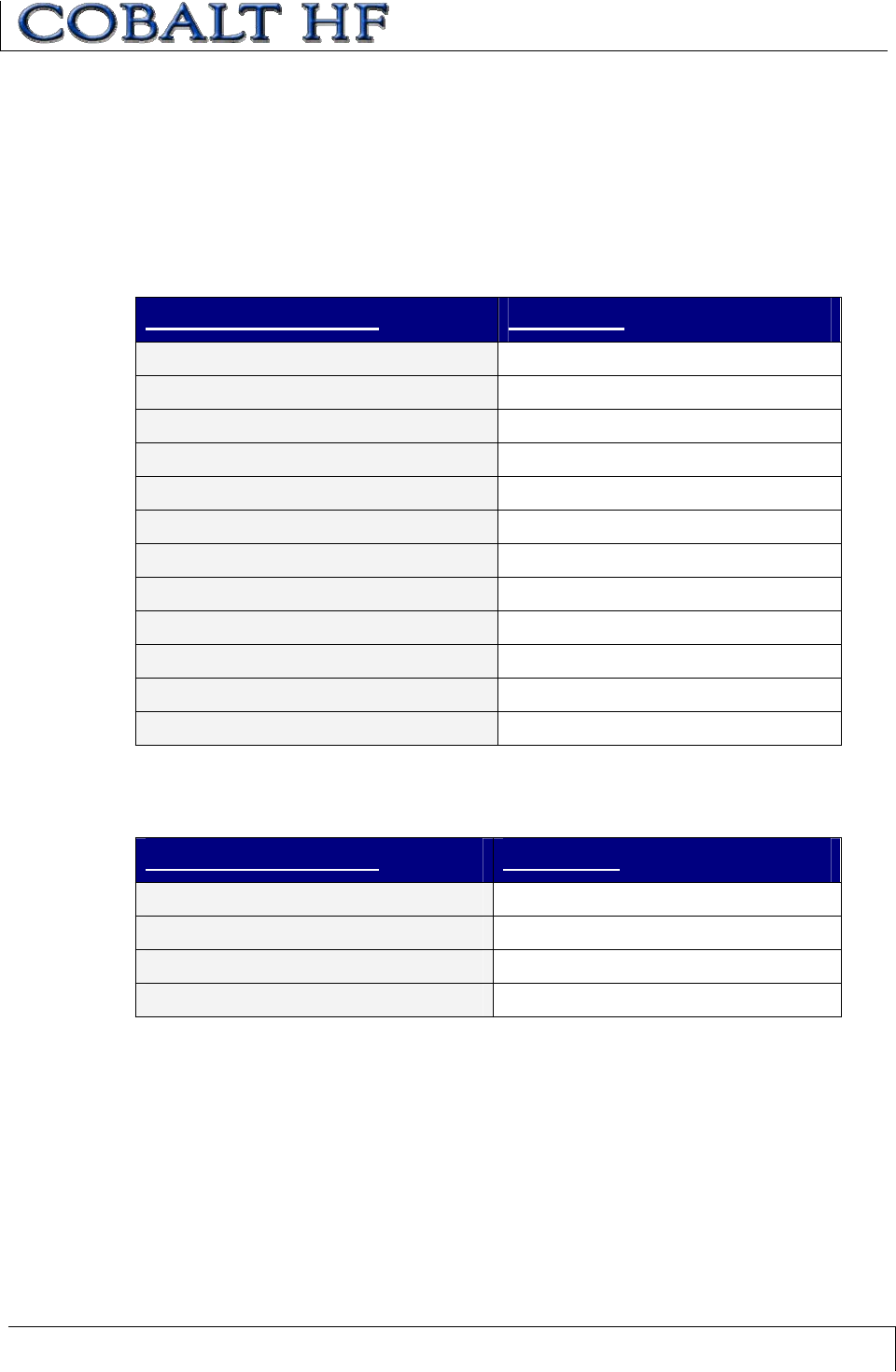
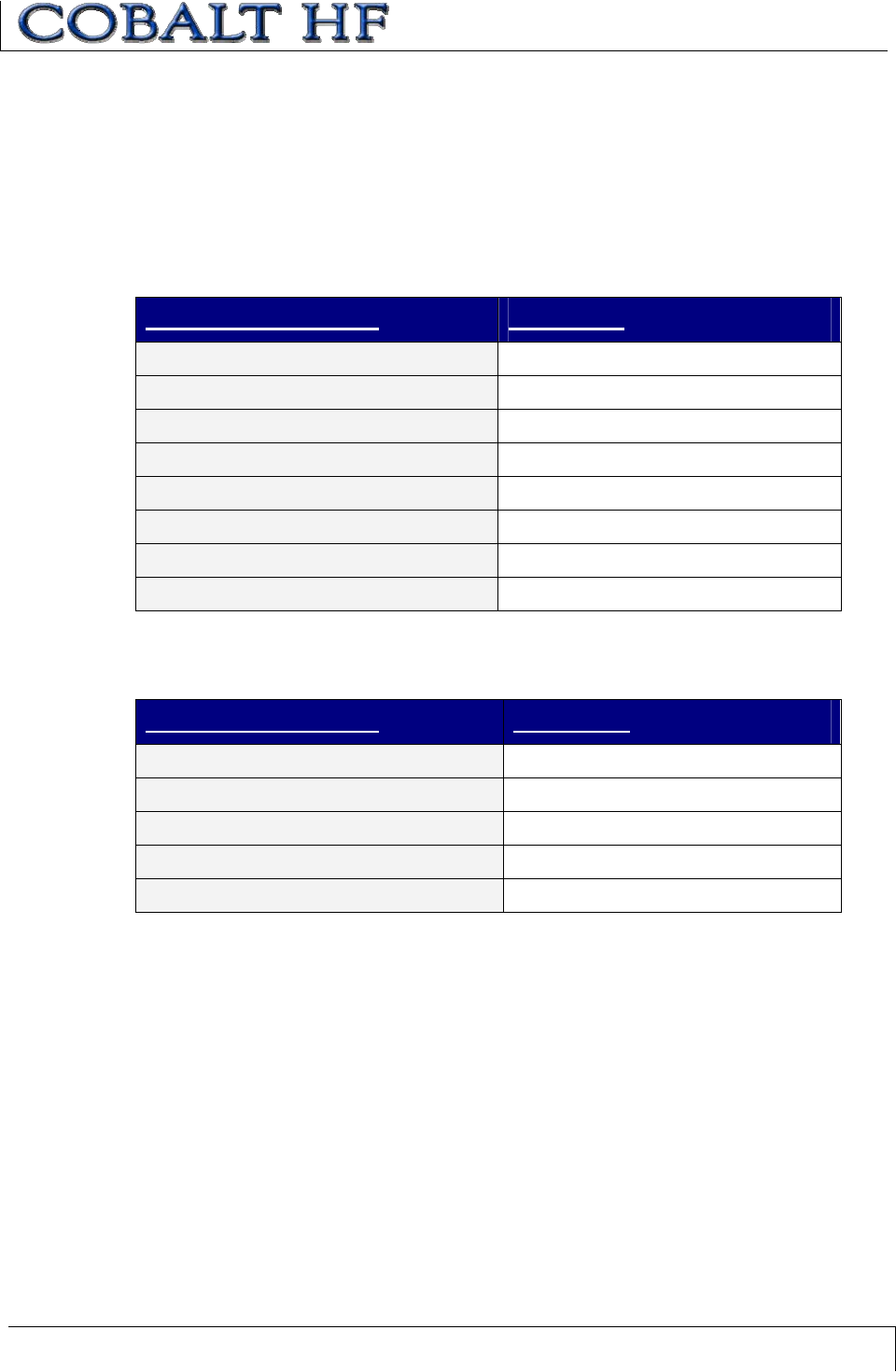
TAG MEMORY MAP EXAMPLE
TAG ADDRESS USAGE
00 – 15 Serial #
16 - 47 Model #
48 - 63 Production Date
64 - 71 Lot #
72 - 89 Factory ID
90 - 111 Reserved for Future Use
Table 5-1: Tag Memory Map Example
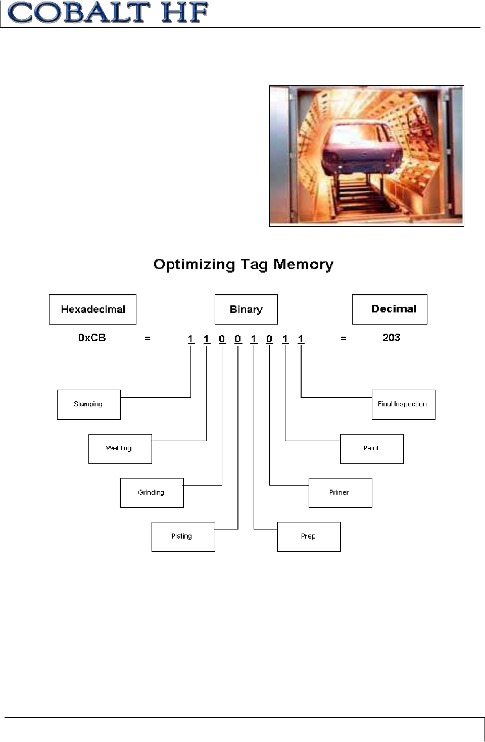
5.5.2 Tag Memory Optimization
Data stored in tag memory is always written in binary (1’s and 0’s). Binary values are
notated using the hexadecimal numbering system (otherwise it might be confusing
viewing a page full of 1’s and 0’s).
Below is an example of how hexadecimal notation is used to simplify the process of
expressing the decimal number 52,882.
Decimal Binary Hexadecimal
52,882 1100 1110 1001 0010 CE92
Rather than using five bytes to store the five individual ASCII characters representing the
numerical values 5, 2, 8, 8, and 2 (ASCII bytes: 0x35, 0x32, 0x38, 0x38 and 0x32), by
simply writing two Hex bytes (0xCE and 0x92), 60% less tag memory is required to store
the same amount of information.
When an alphabetical character is to be written to a tag, the Hex equivalent of the ASCII
value is written to the tag. So for example, to write a capital “D” (ASCII value 0x44), the
Hex value 0x44 is written to the tag.
Additionally, if a database with look up values is used in the RFID application, the logic
level of the individual bits within the tag can be used to further maximize tag memory.
(Note: refer to Appendix D in this document for a chart of ASCII characters, their
corresponding Hex values and their decimal value equivalents).
CHAPTER 5: RFID TAGS
COBALT HF RFID CONTROLLERS OPERATOR’S MANUAL
P/N: 17-1320 REV 01 (03-06) PAGE 59 OF 116
OPTIMIZING THE TAG
The following example illustrates how a
single byte (8 bits) can be used to track
an automobile’s inspection history at
eight inspection stations. The number
one (1) represents a required operation
and the number zero (0) represents an
operation that is not required for a
particular vehicle.
CHAPTER 6: COMMAND PROTOCOLS
COBALT HF RFID CONTROLLERS OPERATOR’S MANUAL
P/N: 17-1320 REV 01 (03-06) PAGE 60 OF 116
CHAPTER 6:
COMMAND PROTOCOLS
6.1 COMMAND PROTOCOL OVERVIEW
In order to correctly recognize and execute commands, the Cobalt HF and the host must
be able to communicate using the same language. The language that is used to
communicate is referred to as the Command Protocol.
There are two Command Protocols used by Cobalt HF RFID Controllers.
xABx Fast Command Protocol – for Point-to-Point, Host/Controller applications
(-232, -422 and –USB models).
xCBx Command Protocol – for multiple RFID controller configurations, Multi-
drop (Subnet16) networks and Industrial Ethernet applications (-485 and –IND
models).
These two Command Protocols have different packet structures and parameter settings,
which are explained later in this chapter.
6.2 ABXFAST COMMAND PROTOCOL
The command protocol used by the Cobalt HF -232, -422 and -USB Controllers for Point-
to-Point data transmission is known as the ABx Fast Command Protocol. ABx Fast has
a single-byte oriented packet structure that permits the rapid execution of RFID
commands while requiring the transfer of a minimal number of bytes.
ABx Fast supports the inclusion of an optional checksum byte. By default, the HF-CNTL-
232, -422 and -USB controllers are configured to use ABx Fast without the checksum
option. However, when increased data integrity is required, the checksum should be
utilized. See Section 6.2.4 for more on using the checksum parameter.
6.2.1 ABx Fast - Command / Response Procedure
After an RFID command is issued by the host, a packet of data, called the “Command
Packet” is sent to the Cobalt Controller. The command packet contains information that
instructs the controller to perform a certain task.
The Cobalt Controller automatically parses the incoming data packet, searching for a
specific pair of start characters, known as the “Command Header.” (Note: in ABx Fast,
the Command Header / Start Characters are 0x02, 0x02). When a Command Header is
recognized, the controller then checks for proper formatting and the presence of a
Terminator byte. (Note: in ABx Fast, the Terminator byte is 0x03).
Having identified a valid command, the controller will attempt to execute the instructions,
after which it will generate a host-bound response message containing EITHER the
results of the attempted command or an error code if the operation failed.
All commands will generate a response from the controller. Before sending another
command, the host must first process (remove from memory) any pending response
data.
CHAPTER 6: COMMAND PROTOCOLS
COBALT HF RFID CONTROLLERS OPERATOR’S MANUAL
P/N: 17-1320 REV 01 (03-06) PAGE 61 OF 116
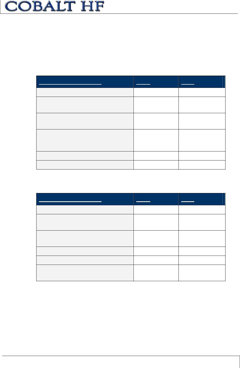
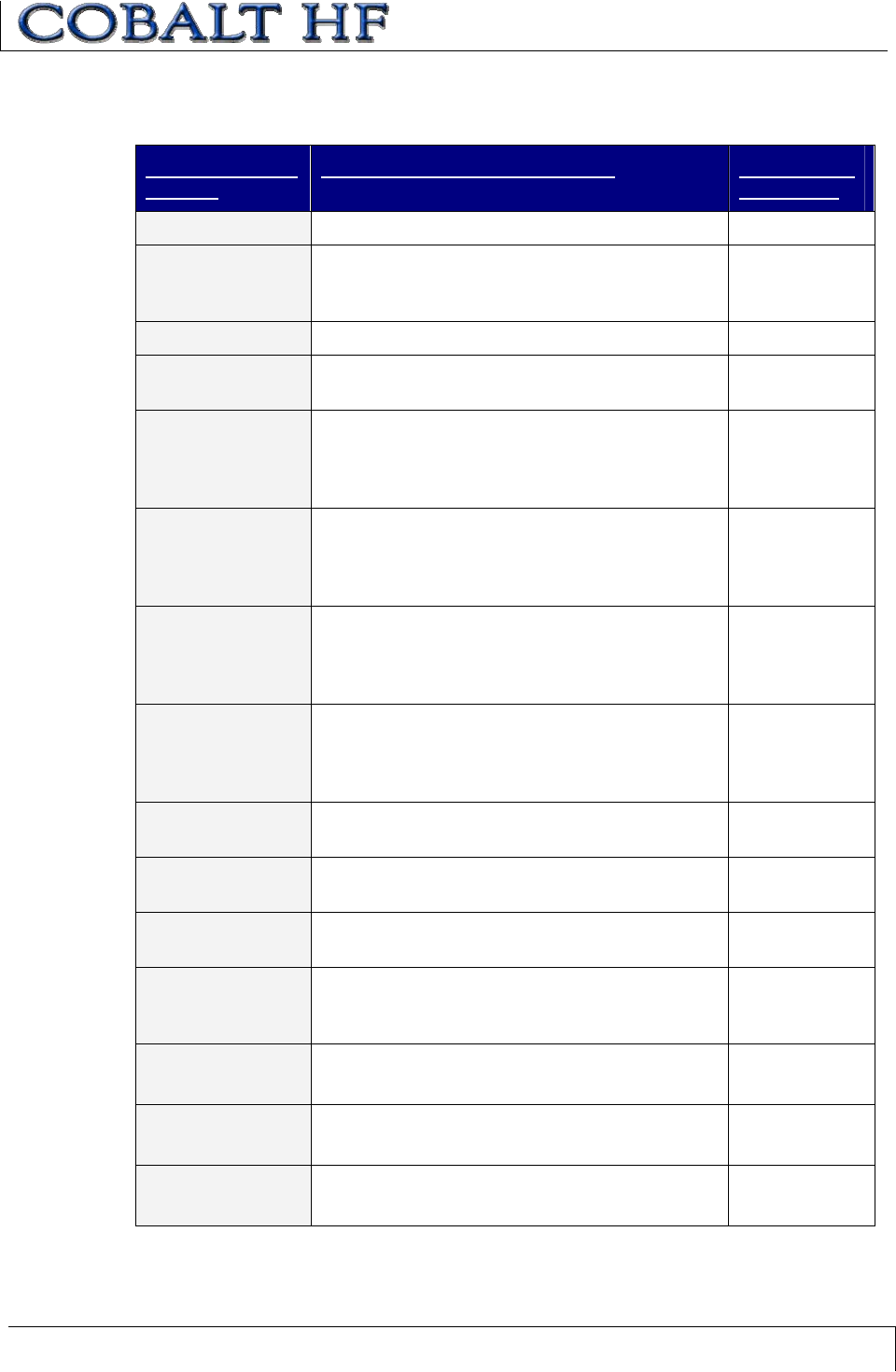
6.2.2 ABx Fast - Command Packet Structure
The packet structure of every ABx Fast command contains certain basic elements,
including a Command Header, a number of command parameters and a Terminator.
COMMAND PACKET PARAMETER CONTENT SIZE
COMMAND HEADER:
The first two bytes of an ABx Fast Command Packet:
0x02, 0x02 2 bytes
COMMAND SIZE:
This 2-byte value defines the number of bytes in the packet
(excluding Header, Command Size, Checksum and
Terminator).
0x0008 2-byte
integer
COMMAND ID:
This single-byte value indicates the RFID command to execute.
0x06
(Write Data)
1 byte
START ADDRESS:
The 2-byte Start Address parameter indicates the location of
tag memory where a read or write operation shall begin.
0x0000 2-byte
integer
READ/WRITE LENGTH:
The 2-byte Read/Write Length parameter represents the
number of bytes that are to be retrieved from or written to the
RFID tag.
0x0001 2-byte
integer
TIMEOUT VALUE:
This 2-byte integer indicates the maximum length of time for
which the controller will attempt to complete the command.
Measured in milliseconds, this value can have a range of
0x0001 to 0xFFFE or between 1 and 65,534 msecs (0x07D0 =
2000 x .001 = 2 seconds).
0x07D0 2-byte
integer
ADDITIONAL DATA:
This parameter uses one byte to hold a single character for fill
operations and supports the use of multiple bytes when several
characters are needed for write commands (when applicable).
0x00 One or
more bytes
(when
applicable)
CHECKSUM:
This optional parameter holds a single-byte checksum (only
applicable when using ABx Fast with Checksum).
optional 1 byte
(when
applicable)
TERMINATOR:
Single-byte command packet terminator:
0x03 1 byte
Table 6-1: ABx Fast - Command Packet Structure
CHAPTER 6: COMMAND PROTOCOLS
COBALT HF RFID CONTROLLERS OPERATOR’S MANUAL
P/N: 17-1320 REV 01 (03-06) PAGE 62 OF 116
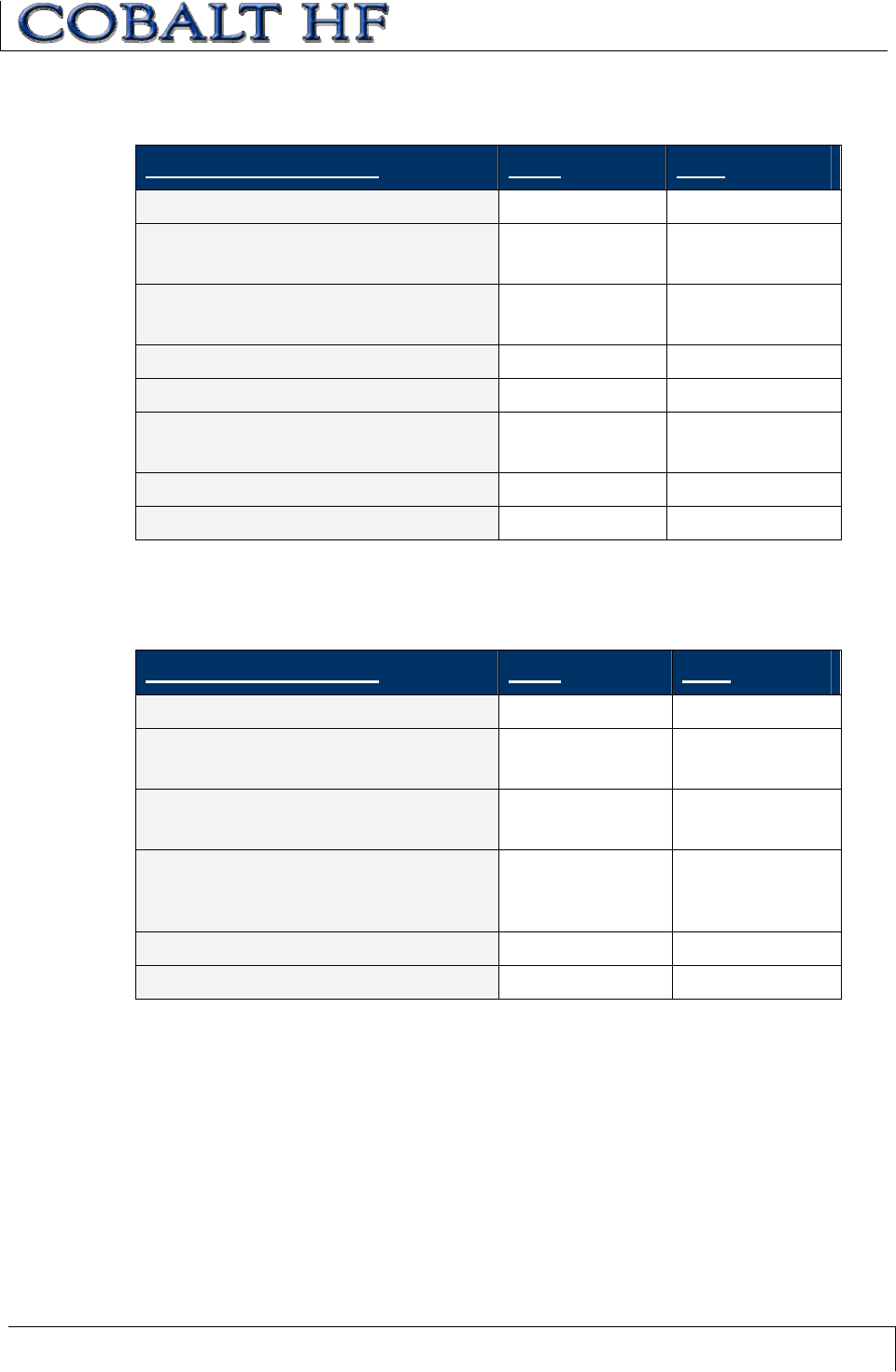
6.2.3 ABx Fast - Response Packet Structure
After performing a command, the Cobalt HF will generate a host-bound response
message. ABx Fast responses contain a Response Header, a number of response
values (or retrieved data bytes), and a Terminator.
RESPONSE PACKET PARAMETER CONTENT SIZE
RESPONSE HEADER:
The first two bytes of an ABx Fast response packet.
0x02, 0x02 2 bytes
RESPONSE SIZE:
This 2-byte integer defines the total number of bytes in
the response packet (excluding Header, Response
Size, Checksum and Terminator).
0x0001 2-byte integer
COMMAND ECHO:
The single-byte Command Echo parameter reiterates
the Hex value of the command for which the response
packet was generated.
0x06 1 byte
RETRIEVED DATA:
This parameter is used to hold one or more bytes of
data that was requested by the command (when
applicable).
Data 1 or more bytes
(when
applicable)
CHECKSUM:
This optional parameter holds a single-byte checksum
(only applicable when using ABx Fast with
Checksum).
Optional 1 byte
(when
applicable)
TERMINATOR:
Single-byte response packet terminator:
0x03 1 byte
Table 6-2: ABx Fast - Response Packet Structure
CHAPTER 6: COMMAND PROTOCOLS
COBALT HF RFID CONTROLLERS OPERATOR’S MANUAL
P/N: 17-1320 REV 01 (03-06) PAGE 63 OF 116
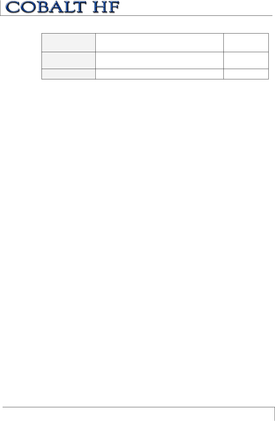
6.2.4 ABx Fast - Command Packet Parameters
COMMAND SIZE
The ABx Fast protocol requires that the byte count, known as the Command Size, be
specified as a 2-byte integer. To calculate Command Size, add the total number of bytes
within the command packet while excluding the two bytes for the Header, the two bytes
for the Command Size, the one byte for the Checksum (if present) and the one byte for
the Terminator (see example below).
PACKET
PARAMETER
# OF
BYTES
INCLUDED IN
COMMAND SIZE?
Header 2 No
Command Size 2 No
Command ID 1Yes
Start Address 2Yes
Read/Write Length 2Yes
Timeout Value 2Yes
Additional Data Bytes 1Yes
Checksum 1 No
Terminator 1 No
In the above command packet example, 8 bytes of data are located between the
Command Size parameter and the Checksum parameter. Therefore, the Command Size
for this example is 0x0008.
START ADDRESS
The Start Address parameter is holds a two-byte integer representing the tag memory
address location where a read or write operation will begin.
READ/WRITE LENGTH
The two-byte Read/Write Length parameter indicates the number of bytes that are to be
read from or written to the RFID tag.
Command
Size = number
of bytes in
these fields
CHAPTER 6: COMMAND PROTOCOLS
COBALT HF RFID CONTROLLERS OPERATOR’S MANUAL
P/N: 17-1320 REV 01 (03-06) PAGE 64 OF 116
TIMEOUT VALUE PARAMETER
ABx Fast commands include a two-byte Timeout Value parameter (measured in
increments of one millisecond) that is used to limit the length of time that the Cobalt HF
will attempt to complete a specified operation.
The maximum Timeout Value is 0xFFFE or 65,534 milliseconds (slightly longer than one
minute). Setting a long Timeout Value does not necessarily mean that a command will
take any longer to execute. This value only represents the period of time for which the
Cobalt HF will attempt execution of the command.
IMPORTANT
During write commands, the tag must remain within the antenna’s RF field until the write
operation completes successfully, or until the Timeout Value has expired.
If a write operation is not completed before the tag leaves the controller’s RF field, data
may be incompletely written.
CHECKSUM PARAMETER
The ABx Fast Command Protocol supports the inclusion of an additional checksum byte
that is used to verify the integrity of data being transmitted between host and controller.
The checksum is calculated by adding together (summing) the byte values in the
command packet (less the Header, Checksum and Terminator parameters), and then
subtracting the total byte sum from 0xFF. Therefore, when the byte values of each
parameter (from Command Size to Checksum) are added together, the byte value sum
will equal 0xFF.
To enable the use of the checksum parameter, download the RFID Dashboard Utility
from www.ems-rfid.com, and use it to set the ABx Protocol parameter to ABx Fast with
Checksum.
CHAPTER 6: COMMAND PROTOCOLS
COBALT HF RFID CONTROLLERS OPERATOR’S MANUAL
P/N: 17-1320 REV 01 (03-06) PAGE 65 OF 116
CHECKSUM EXAMPLE
The following example depicts Command 0x05 (Read Data) using a checksum.
COMMAND
PARAMETER
CONTENTS USED IN CHECKSUM
Header 0x02, 0x02 n/a
Command Size 0x0007 0x00, 0x07
Command ID 0x05 0x05
Start Address 0x0001 0x00, 0x01
Read Length 0x0004 0x00, 0x04
Timeout Value 0x07D0 0x07, 0xD0
Checksum 0x17 n/a
Terminator 0x03 n/a
Add the byte values from the Command Size, Command ID, Start Address, Read Length
and Timeout Value parameters together and subtract from 0xFF. Resulting value will be
the checksum.
[0x07 + 0x05 + 0x01 + 0x04 + 0x07 + 0xD0] = 0xE8
The checksum equation is: [0xFF – 0xE8] = 0x17
Checksum =
[0xFF – (sum
of these
fields)]

CHAPTER 6: COMMAND PROTOCOLS
COBALT HF RFID CONTROLLERS OPERATOR’S MANUAL
P/N: 17-1320 REV 01 (03-06) PAGE 66 OF 116
6.3 CBXCOMMAND PROTOCOL
The CBx Command Protocol, utilized by the Cobalt -485 and -IND models, includes
Multi-drop Subnet16 networking support for use with Industrial Ethernet applications.
CBx is based on a double-byte oriented packet structure where commands always
contain a minimum of six data “words,” even when one (or more) parameters are not
applicable to the command. CBx does not support the inclusion of a checksum byte.
The CBx packet structures described herein are protocol independent and can be
implemented the same for all Industrial Ethernet protocols (Ethernet/IP, Modbus TCP,
etc.).
6.3.1 CBx – Command Procedure
COBALT HF-CNTL-485-01 – COMMAND PROCEDURE
Commands are initiated by a host PC or Programmable Logic Controller (PLC) and are
distributed to the controller via a Subnet16 Gateway or Subnet16 Hub Interface Device
that is connected to the host or PLC by standard Ethernet cabling.
After a command is sent, it is executed either directly by the interface device (Gateway or
Hub) or is otherwise routed to the RFID controller specified in the command. Note that
when issuing controller-bound commands, instructions are directed to the appropriate
RFID controller by specifying the “Node ID Number” of the particular controller. Each
Cobalt -485 Controller on a Multi-drop Subnet16 network is assigned an individual Node
ID number.
COBALT HF-CNTL-IND-01 – COMMAND PROCEDURE
Commands are initiated by a host PC or Programmable Logic Controller (PLC) and are
distributed directly to the controller via an M12 D-Code to Ethernet cable.
After a command is sent, it is immediately executed by the Cobalt Controller. Note that
instructions are directed to the controller by specifying in the command the “Node ID
Number” of the Cobalt Controller. For the Cobalt HF-CNTL-IND-01, the Node ID will
always be 01 (0x01).
6.3.2 CBx – Response Procedure
Following the execution of an RFID command, the controller will automatically generate a
host-bound response message that contains EITHER the results of the attempted
command or an error code if the operation could no be completed successfully.
Similar to ABx Fast, all CBx commands will generate a response from the controller.
Before the host can send another command to the controller, it must first process
(remove from memory) the controller’s pending response data.
CHAPTER 6: COMMAND PROTOCOLS
COBALT HF RFID CONTROLLERS OPERATOR’S MANUAL
P/N: 17-1320 REV 01 (03-06) PAGE 67 OF 116
6.3.3 CBx - Command Packet Structure
As noted, CBx commands contain a minimum of six words. Below is the structure of a
standard CBx command packet. For the Cobalt HF-CNTL-485-01 model, refer to the
Subnet16 Gateway or Subnet16 Hub - Operator’s Manuals.
WORD
#
COMMAND PACKET PARAMETER MSB LSB
01 Overall Length: 2-byte integer indicating the number
of 16-bit “words” in the entire command packet. This
value will always be at least 6, as each command has
a minimum of 12-bytes (or 6 words). Overall Length
will increase when additional data words are used in
the command (for fills, writes, etc.).
0x00 0x06 +
(number of
additional data
words, if any)
02 AA in MSB
Command ID: single-byte value indicating command
to perform in LSB.
0xAA Command ID
03 00 in MSB
Node ID: single-byte Node ID number of the controller
to which the command is intended. (Must be 0x01 for
Cobalt -IND).
0x00 0x01
04 Timeout Value: 2-byte integer representing the length
of time allowed for the completion of the command,
measured in 1 millisecond units (when applicable).
Timeout
MSB
Timeout LSB
05 Start Address: 2-byte integer indicating the location of
tag memory where the Read/Write operation will begin
(when applicable).
Start MSB Start LSB
06 Read/Write Length: 2-byte integer indicating the
number of bytes that are to be Read/Written beginning
at the Start Address (when applicable).
Length
MSB
Length LSB
07 Additional Data – (bytes 1 & 2) used to hold 2-bytes
of data used for writes and fills (when applicable).
D1 D2
08 Additional Data – (bytes 3 & 4): used to hold 2-bytes
of data for writes and fills (when applicable).
D3 D4
Table 6-3: CBx - Command Packet Structure
CHAPTER 6: COMMAND PROTOCOLS
COBALT HF RFID CONTROLLERS OPERATOR’S MANUAL
P/N: 17-1320 REV 01 (03-06) PAGE 68 OF 116
6.3.4 CBx - Response Packet Structure
After performing a command, the Cobalt HF RFID Controller will issue a host-bound
response message. Below is the packet structure of a standard CBx response message.
WORD
#
RESPONSE PACKET
PARAMETER
MSB LSB
01 Overall Length: 2-byte value indicating the
number of “words” in the response packet.
This value will always be at least 6 words.
0x00 06 + (number of
additional data
words retrieved)
02 AA in MSB
Command Echo: single-byte value
indicating the command that was performed
in LSB.
0xAA Command Echo
03 Instance Counter in MSB
(see description below)
Node ID Echo in LSB (will be 0x01 for the
Cobalt -IND)
Instance
Counter
Node ID Echo
04 Month and Day timestamp Month DOM
05 Hour and Minute timestamp Hour Minutes
06 Second timestamp in MSB
Number of Additional Data Bytes
Retrieved in LSB
Seconds N-bytes
07 Retrieved Data – (bytes 1 & 2) used to hold
2-bytes of retrieved data (when applicable).
D1 D2
08 Retrieved Data – (bytes 3 & 4) used to hold
2-bytes of retrieved data (when applicable).
D3 D4
Table 6-4: CBx - Response Packet Structure
INSTANCE COUNTER
The Instance Counter is a one-byte value used by a Subnet16 Gateway or Subnet16
Hub to track the number of responses generated by a given Node ID number. The
Gateway/Hub tallies in its internal RAM separate Instance Counter values for each Node
ID. The Instance Counter value is incremented by one following each response. If, for
example, 10 responses were generated by the controller assigned Node ID 01, its
Instance Counter value will read 10. When the Gateway/Hub is power cycled or
rebooted, all Instance Counter values will be reset to zero (0x00).
CHAPTER 6: COMMAND PROTOCOLS
COBALT HF RFID CONTROLLERS OPERATOR’S MANUAL
P/N: 17-1320 REV 01 (03-06) PAGE 69 OF 116
6.3.5 CBx - Command Example
In the example below, Command 0x05 (Read Data) is issued to the Cobalt Controller
assigned to Node ID 01. The controller will be instructed to read 4 bytes of data from a
tag beginning at tag address 0x20. The Timeout Value has been set to two seconds for
the completion of this command (0x07D0 = 2000 x .001 = 2 seconds).
WORD # DESCRIPTION MSB LSB
01 Overall Length of Command (in words)0x00 0x06
02 AA in MSB
Command ID in LSB: (0x05: Read Data)
0xAA 0x05
03 00 in MSB
Node ID in LSB: (0x01 for the Cobalt)
0x00 0x01
04 2-byte Timeout Value measured in ms 0x07 0xD0
05 2-byte Start Address for the Read
Operation: (0x0020)
0x00 0x20
06 2-byte Read Length: (0x0004)0x00 0x04
6.3.6 CBx - Response Example
Below is an example of a typical controller response after successfully executing the
Read Data command (as issued in the previous example).
WORD # DESCRIPTION MSB LSB
01 Overall Length of Response
(in words)
0x00 0x08
02 AA in MSB
Command Echo in LSB:
(0x05 Read Data)
0xAA 0x05
03 00 in MSB
Node ID Echo in LSB
0x00 0x01
04 Month and Day timestamp:
(March 19th)
0x03 0x13
05 Hour and Minute timestamp
(10:11: AM)
0x0A 0x0B
06 Seconds timestamp in MSB
(:36 seconds)
# of Additional Data Bytes
Retrieved in LSB: (0x04)
0x24 0x04
07 Retrieved Data (bytes 1 & 2)0x01 0x02
08 Retrieved Data (bytes 3 & 4)0x03 0x04
CHAPTER 7: RFID COMMANDS
COBALT HF RFID CONTROLLERS OPERATOR’S MANUAL
P/N: 17-1320 REV 01 (03-06) PAGE 70 OF 116
CHAPTER 7:
RFID COMMANDS
Most RFID commands can be divided into two primary categories: READ and WRITE.
Read commands retrieve data from a tag or obtain information from the controller. Write
commands transfer information to a tag or update settings on the controller.
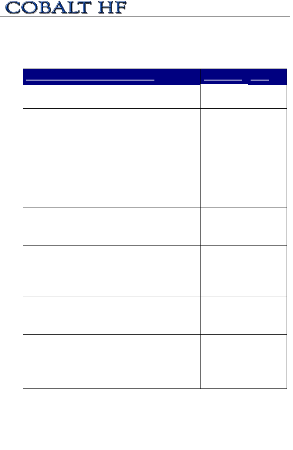
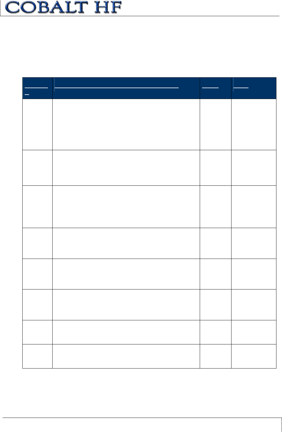
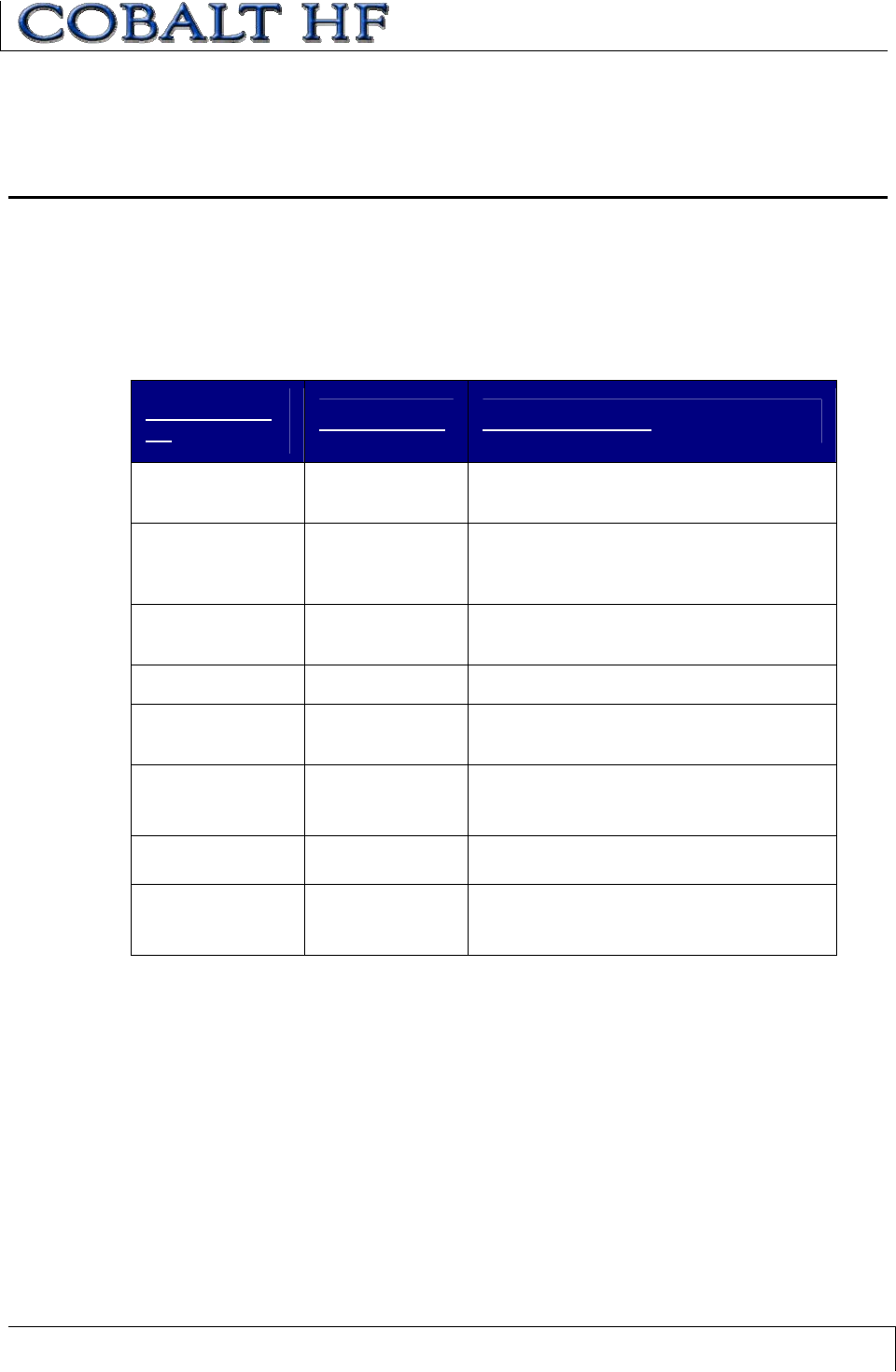
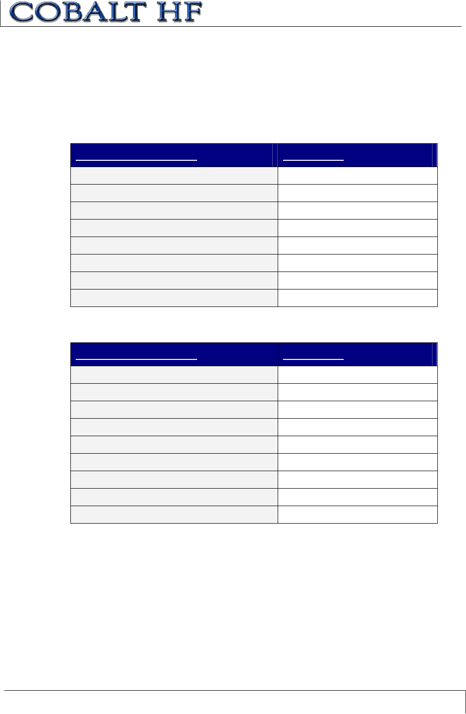
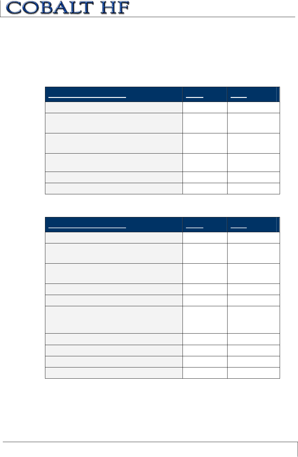
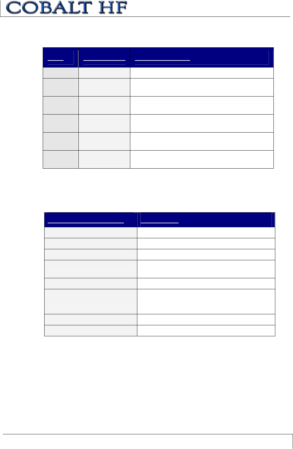
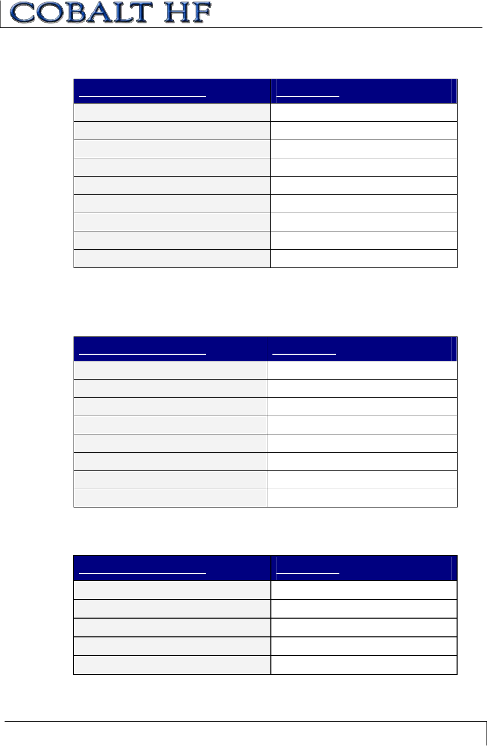
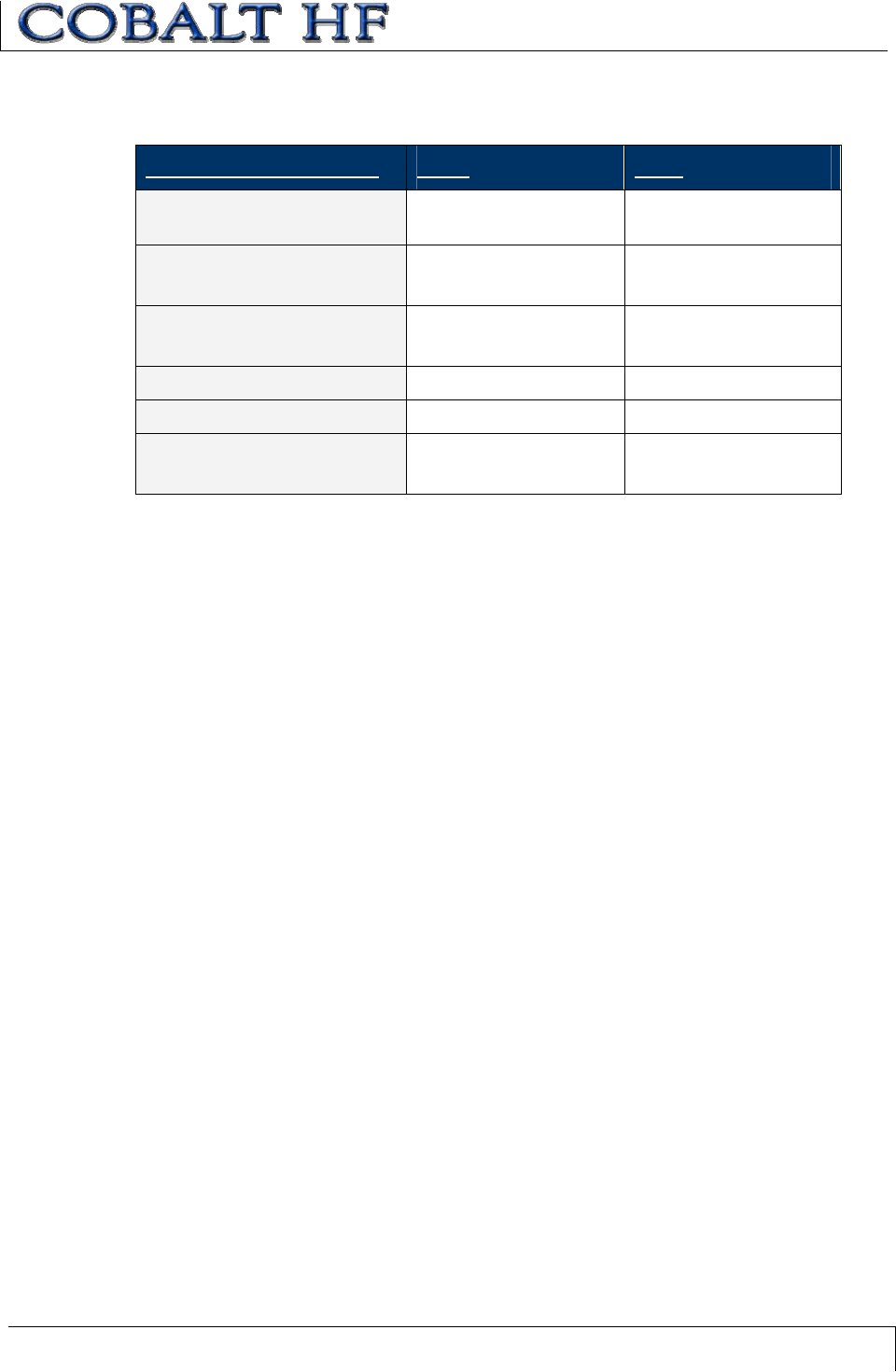
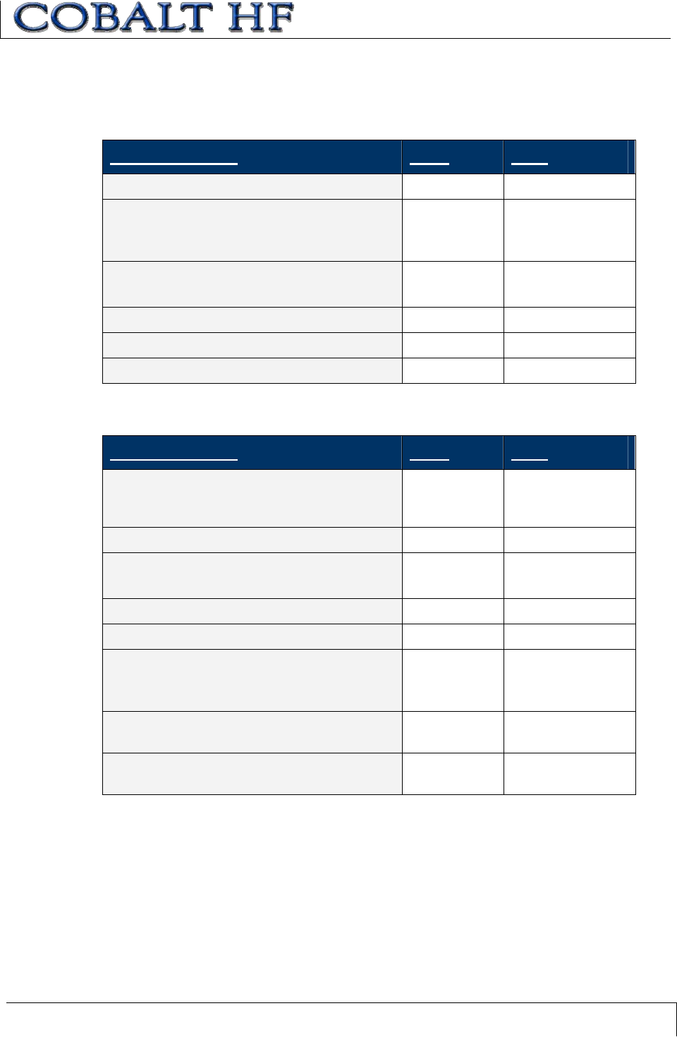
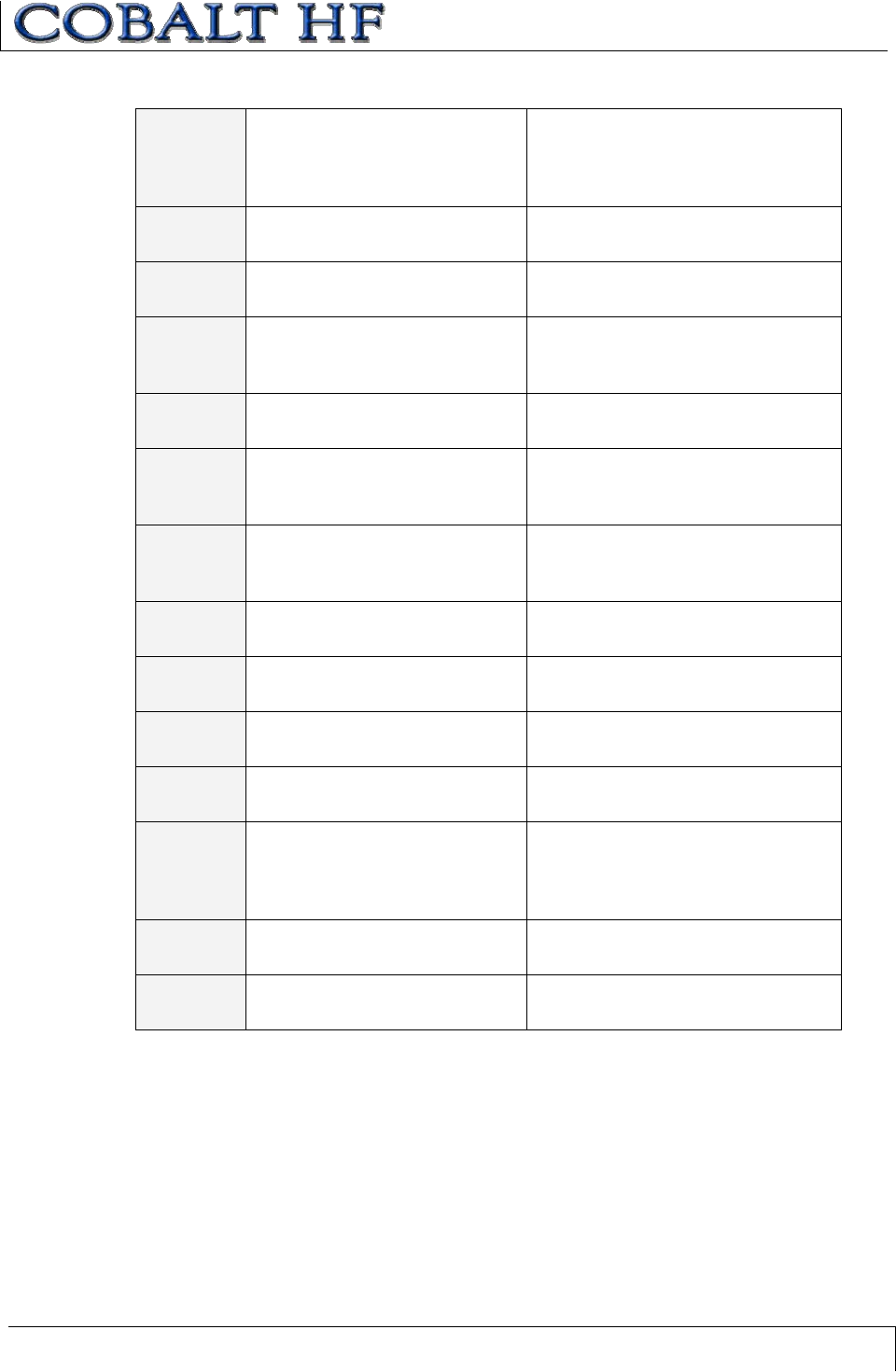
7.1 RFID COMMANDS TABLE
COMMAND
ID COMMAND DESCRIPTION
0x04 Fill Tag Writes a specified data byte to all defined
tag addresses.
0x05 Read Data
Reads a specified length of data from
contiguous (sequential) areas of tag
memory.
0x06 Write Data Writes a specified number of bytes to a
contiguous area of tag memory.
0x07 Read Tag ID Reads a tag’s unique tag ID number.
0x08 Tag Search Instructs the controller to search for a tag
in its RF field.
0x0D
Start/Stop
Continuous
Read
Instructs the controller to start or stop
Continuous Read mode.
0x35 Reset
Controller Resets power to the controller.
0x38
Get
Controller
Info
Reads hardware, firmware and serial
number information from the controller.
Table 7-1: RFID Commands Table
CHAPTER 7: RFID COMMANDS
COBALT HF RFID CONTROLLERS OPERATOR’S MANUAL
P/N: 17-1320 REV 01 (03-06) PAGE 71 OF 116
Command 04 instructs the RFID controller to fill multiple contiguous addresses of an
RFID tag with a single data byte value. This command is commonly used to clear
sequential segments of tag memory by writing a one-byte value repeatedly across a
specified range of tag addresses.
This command requires one Data Byte Value, a Start Address and a Fill Length. It will
then proceed to fill the tag with the Data Byte Value, for the specified number of
consecutive bytes, beginning at the Start Address.
When the Start Address is set to zero (0x0000), the fill will begin at the first available byte
of tag memory. When the Fill Length is set to zero (0x0000), the controller will write fill
data from the Start Address to the end of the tag’s memory. The Timeout Value is
measured in 1-millisecond increments and can have a value of 0x0001 to 0xFFFE (1 -
65,534 milliseconds). If the Fill Length extends beyond the last byte in the tag, the
controller will return an error.
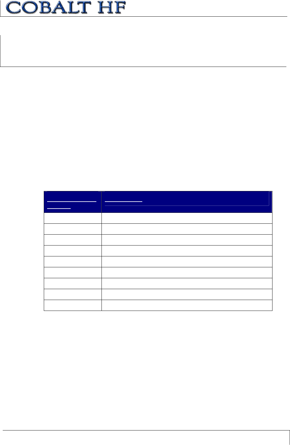
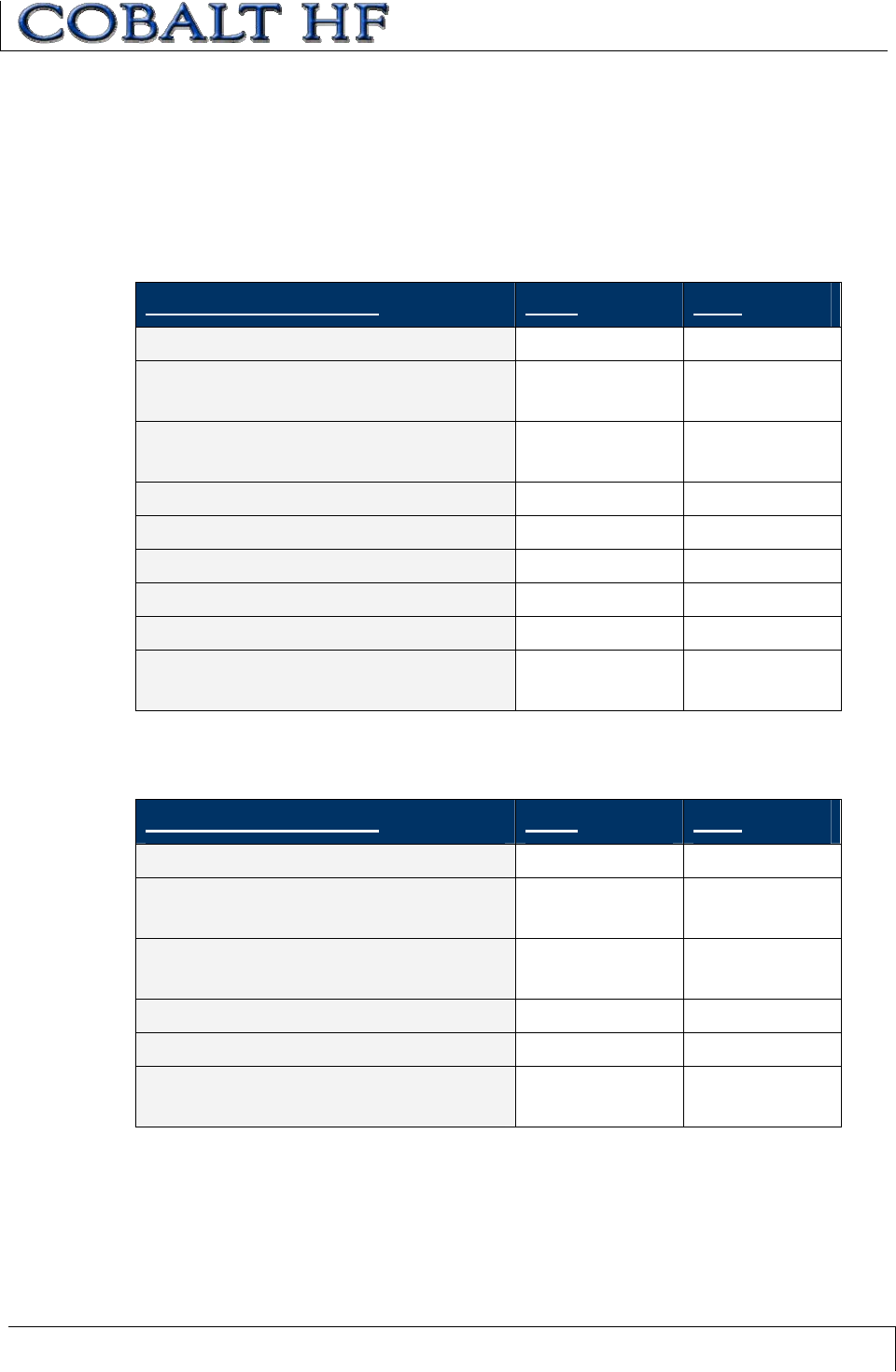
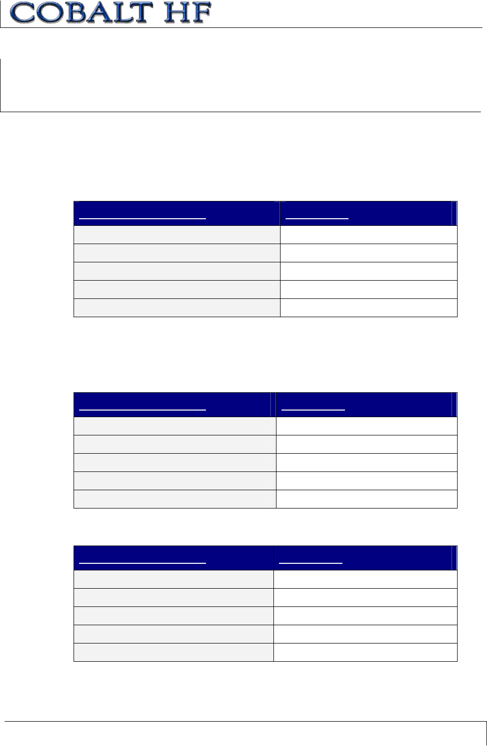
COMMAND 04 (FILL TAG)-ABXFAST COMMAND STRUCTURE
PARAMETER
FIELD
CONTENT
Header 0x02, 0x02 (the header for all ABx Fast commands).
Command Size 0x0008
Command ID 1-byte Command ID Number (0x04).
Start Address 2-byte value indicating tag address where fill will start.
Fill Length 2-byte value indicating the total number of bytes to be filled.
Timeout Value 2-byte value (0x0001 – 0xFFFE).
Data Byte Value 1-byte value for the data byte to be used as fill.
Checksum Optional
Terminator 0x03 (the terminator for all ABx Fast commands).
COMMAND 04:
FILL TAG
CHAPTER 7: RFID COMMANDS
COBALT HF RFID CONTROLLERS OPERATOR’S MANUAL
P/N: 17-1320 REV 01 (03-06) PAGE 72 OF 116
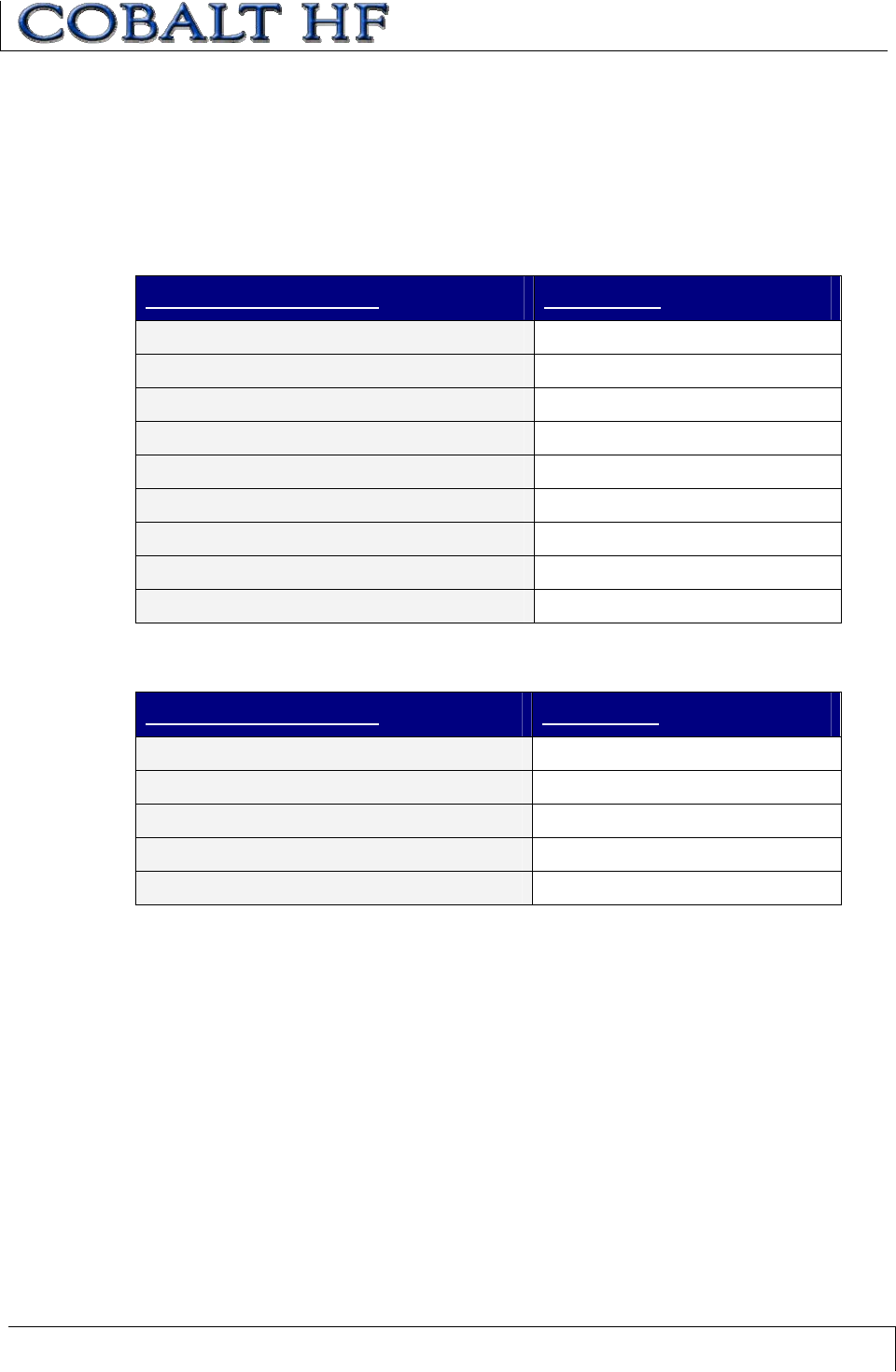
COMMAND 04 (FILL TAG)-ABXFAST COMMAND EXAMPLE
This example instructs the Cobalt HF to fill an entire tag with the ASCII character 'A'
(Data Byte Value 0x41) starting at the beginning of the tag (address 0x0000). A Timeout
Value of 2 seconds (0x07D0) is set for the completion of the command.
Command from Host
PARAMETER FIELD CONTENT
Header 0x02, 0x02
Command Size 0x0008
Command ID 0x04
Start Address 0x0000
Fill Length 0x0000
Timeout Value 0x07D0
Data Byte Value 0x41
Checksum Optional
Terminator 0x03
Response from Controller
PARAMETER FIELD CONTENT
Header 0x02, 0x02
Response Size 0x0001
Command Echo 0x04
Checksum Optional
Terminator 0x03
CHAPTER 7: RFID COMMANDS
COBALT HF RFID CONTROLLERS OPERATOR’S MANUAL
P/N: 17-1320 REV 01 (03-06) PAGE 73 OF 116
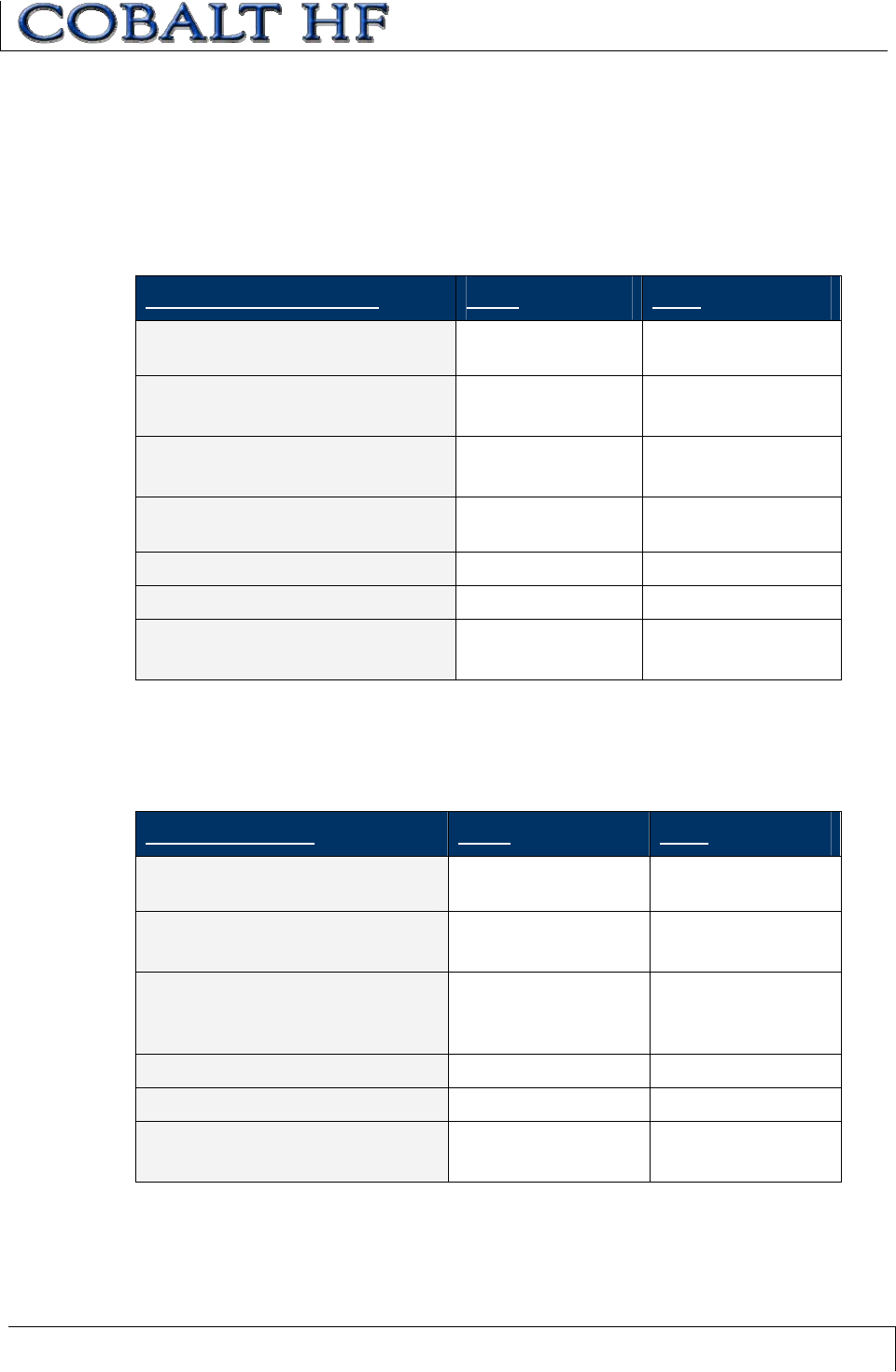
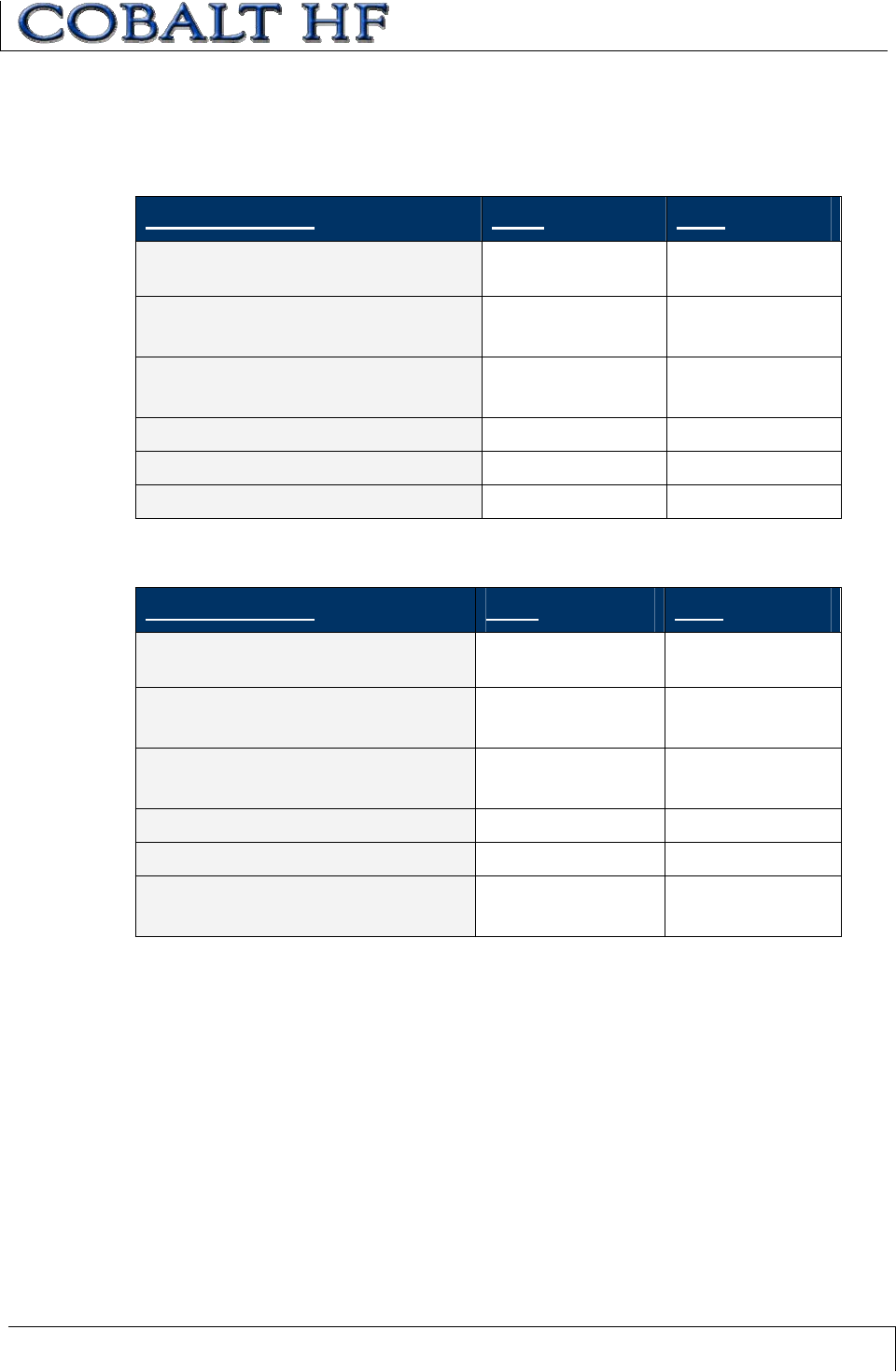
COMMAND 04 (FILL TAG)-CBXCOMMAND EXAMPLE
This example instructs the Cobalt Controller to fill an entire tag with the ASCII character
'A' (Data Byte Value 0x41) starting at the beginning of the tag (address 0x0000). A
Timeout Value of 2 seconds (0x07D0) is set for the completion of the command.
Command from Host
PARAMETER FIELD MSB LSB
Overall Length of Command
(in words)
0x00 0x07
AA in MSB
Command ID in LSB: (0x04)
0xAA 0x04
00 in MSB
Node ID in LSB (Cobalt –IND = 01)
0x00 0x01
2-byte Timeout Value measured in
ms (0x07D0 = 2 seconds)
0x07 0xD0
Start Address 0x00 0x00
Fill Length 0x00 0x00
Fill Byte in MSB (A = 0x41)
00 in LSB
0x41 0x00
Note: The “Fill Length” in the Tag Fill Command represents the number of bytes to fill on
the tag, not the length of the ‘fill byte data’ provided in the command, which is always just
a single byte.
Response from Controller
DESCRIPTION MSB LSB
Overall Length of Response
(in words)
0x00 0x06
AA in MSB
Command Echo in LSB (0x04)
0xAA 0x04
00 in MSB
Node ID Echo in LSB
(Cobalt –IND = 0x01)
0x00 0x01
Month and Day timestamp Month DOM
Hour and Minute timestamp Hour Minutes
Seconds timestamp in MSB
00 in LSB
Seconds 0x00
CHAPTER 7: RFID COMMANDS
COBALT HF RFID CONTROLLERS OPERATOR’S MANUAL
P/N: 17-1320 REV 01 (03-06) PAGE 74 OF 116
Command 05 instructs the controller to retrieve a specific number of bytes of data from a
contiguous (sequential) area of an RFID tag’s memory.
When the Start Address is set to zero (0x0000), the controller will start reading at the
beginning (or first accessible byte) of the tag. The minimum Read Length is one byte, the
maximum is the entire read/write address space of the tag. Timeout Value is measured in
1-millisecond increments and can have a value of 0x0001 to 0xFFFE (1 to 65,534
milliseconds). If the Read Length exceeds beyond the last available tag address, the
controller will return an error code.
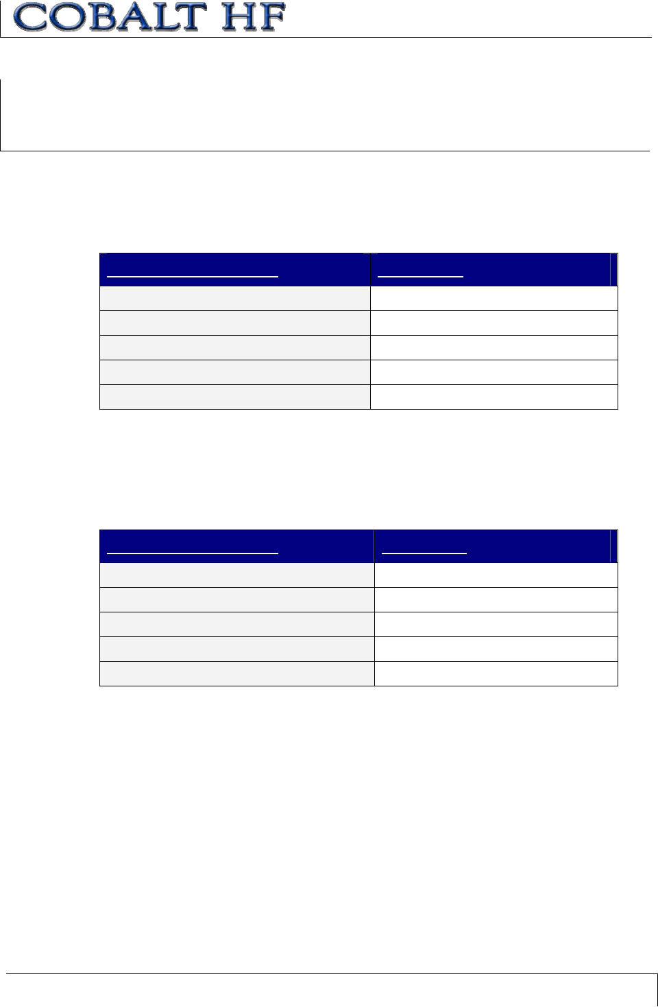
COMMAND 05 (READ DATA)-ABXFAST COMMAND STRUCTURE
PARAMETER FIELD CONTENT
Header 0x02, 0x02
Command Size 0x0007
Command ID 1-byte Command ID (0x05).
Start Address 2-byte value for the starting read
address.
Read Length 2-byte value for the number of bytes to
read.
Timeout Value 2-byte value measured in 1-ms units
(0x0001 – 0xFFFE).
Checksum Optional
Terminator 0x03
COMMAND 05:
READ DATA
CHAPTER 7: RFID COMMANDS
COBALT HF RFID CONTROLLERS OPERATOR’S MANUAL
P/N: 17-1320 REV 01 (03-06) PAGE 75 OF 116
COMMAND 05 (READ DATA)-ABXFAST COMMAND EXAMPLE
This example instructs the controller to read four bytes of data from a tag starting at
address 0x0001. A Timeout Value of 2 seconds (0x07D0 = 2000 x 1 millisecond
increments) is set for the completion of the command.
Command from Host
PARAMETER FIELD CONTENT
Header 0x02, 0x02
Command Size 0x0007
Command ID 0x05
Start Address 0x0001
Read Length 0x0004
Timeout Value 0x07D0
Checksum Optional
Terminator 0x03
Response from Controller
PARAMETER FIELD CONTENT
Header 0x02, 0x02
Response Size 0x0005
Command Echo 0x05
Data from Address 0x0001 0x05
Data from Address 0x0002 0xAA
Data from Address 0x0003 0xE7
Data from Address 0x0004 0x0A
Checksum Optional
Terminator 0x03
CHAPTER 7: RFID COMMANDS
COBALT HF RFID CONTROLLERS OPERATOR’S MANUAL
P/N: 17-1320 REV 01 (03-06) PAGE 76 OF 116
COMMAND 05 (READ DATA)-CBXCOMMAND EXAMPLE
This example instructs the controller to read four bytes of data from a tag starting at
address 0x0001. A Timeout Value of 2 seconds (0x07D0 = 2000 x 1 millisecond
increments) is set for the completion of the command.
Command from Host
PARAMETER FIELD MSB LSB
Overall Length of Command (in words)0x00 0x06
AA in MSB
Command ID in LSB (0x05)
0xAA 0x05
0x00 in MSB
Node ID in LSB (Cobalt -IND = 0x01)
0x00 0x01
2-byte Timeout Value measured in ms
(0x07D0 = 2 seconds)
0x07 0xD0
Start Address 0x00 0x01
Read Length 0x00 0x04
Response from Controller
PARAMETER FIELD MSB LSB
Overall Length of Response (in words)0x00 0x08
AA in MSB
Command Echo in LSB
0xAA 0x05
00 in MSB
Node ID Echo in LSB
0x00 0x01
Month and Day timestamp Month DOM
Hour and Minute timestamp Hour Minutes
Seconds timestamp in MSB
# of Bytes Read Data in LSB
Seconds 0x04
Read Data (bytes 1 and 2)0x01 0x02
Read Data (bytes 3 and 4)0x03 0x04
CHAPTER 7: RFID COMMANDS
COBALT HF RFID CONTROLLERS OPERATOR’S MANUAL
P/N: 17-1320 REV 01 (03-06) PAGE 77 OF 116
Command 06 instructs the controller to write information to an RFID tag. This command
is used to store segments of data in contiguous tag memory locations. It is capable of
transferring up to 100 bytes of data from the host to the tag with one command.
The shortest possible Write Length is one (0x0001). When the Start Address is set to
zero (0x0000), the controller will begin writing to the first available byte of tag memory.
The Timeout Value is measured in 1-millisecond increments and can have a value of
0x0001 to 0xFFFE (1 to 65,534 milliseconds). If the Write Length exceeds beyond the
last available tag address, the controller will return an error code.
COMMAND 06 (WRITE DATA)-ABXFAST COMMAND STRUCTURE
PARAMETER FIELD CONTENT
Header 0x02, 0x02
Command Size 0x0007 + N (where N = the number of Data Bytes
to be written).
Command ID 0x06
Start Address 2-byte value for the tag address where the write
will begin.
Write Length 2-byte value for the number of bytes to write.
Timeout Value 2-byte value measured in 1 millisecond units
(0x0001 – 0xFFFE).
Data Byte Value 1-byte for each data value to be written to tag.
Checksum Optional
Terminator 0x03
COMMAND 06:
WRITE DATA
CHAPTER 7: RFID COMMANDS
COBALT HF RFID CONTROLLERS OPERATOR’S MANUAL
P/N: 17-1320 REV 01 (03-06) PAGE 78 OF 116
COMMAND 06 (WRITE DATA)–ABXFAST COMMAND EXAMPLE
This example writes the five ASCII characters H, E, L, L, O (Data Byte Values: 0x48,
0x45, 0x4C, 0x4C and 0x4F) to the tag starting at address 0x0000. A Timeout Value of 2
seconds (0x07D0 = 2000 x 1 millisecond increments) is set for the completion of this
command.
Command from Host
PARAMETER FIELD CONTENT
Header 0x02, 0x02
Command Size 0x000C
Command ID 0x06
Start Address 0x0000
Write Length 0x0005
Timeout Value 0x07D0
Data Byte Value = H 0x48
Data Byte Value = E 0x45
Data Byte Value = L 0x4C
Data Byte Value = L 0x4C
Data Byte Value = O 0x4F
Terminator 0x03
Response from Controller
PARAMETER FIELD CONTENT
Header 0x02, 0x02
Response Size 0x0001
Command Echo 0x06
Terminator 0x03
CHAPTER 7: RFID COMMANDS
COBALT HF RFID CONTROLLERS OPERATOR’S MANUAL
P/N: 17-1320 REV 01 (03-06) PAGE 79 OF 116
COMMAND 06 (WRITE DATA)–CBXCOMMAND EXAMPLE
This example writes the five ASCII characters H, E, L, L, O (Data Byte Values: 0x48,
0x45, 0x4C, 0x4C and 0x4F) to the tag starting at address 0x0000. A Timeout Value of 2
seconds (0x07D0 = 2000 x 1 millisecond increments) is set for the completion of this
command.
Command from Host
PARAMETER FIELD MSB LSB
Overall Length of Command (in words)0x00 0x09
AA in MSB
Command ID in LSB (0x06)
0xAA 0x06
00 in MSB
Node ID in LSB (Cobalt -IND = 01)
0x00 0x01
2-byte Timeout Value measured in ms 0x07 0xD0
Start Address 0x00 0x00
Length of Write (in bytes)0x00 0x05
Write Data (bytes 1 and 2)0x48 0x45
Write Data (bytes 3 and 4)0x4C 0x4C
Write Data (byte 5) in MSB
00 in LSB
0x4F 0x00
Response from Controller
PARAMETER FIELD MSB LSB
Overall Length of Response (in words)0x00 0x06
AA in MSB
Command Echo in LSB
0xAA 0x06
00 in MSB
Node ID Echo in LSB (Cobalt = 01)
0x00 0x01
Month and Day timestamp Month DOM
Hour and Minute timestamp Hour Minutes
Seconds timestamp in MSB
00 in LSB
Seconds 0x00
CHAPTER 7: RFID COMMANDS
COBALT HF RFID CONTROLLERS OPERATOR’S MANUAL
P/N: 17-1320 REV 01 (03-06) PAGE 80 OF 116
This command instructs the RFID controller to locate a tag in RF range and retrieve its
unique tag identification number.
RFID tags are assigned a unique tag ID number during the manufacturing process. After
a tag ID number has been assigned to a tag, the value cannot be altered and is not
considered part of the available read/write memory space of the tag.
x ISO 14443 compliant tags receive a 4-byte tag ID number. By using just four
bytes, tag manufacturers can generate over 4.2 billion possible ISO 14443
compliant tag ID numbers.
x ISO 15693 compliant tags are given an 8-byte tag ID number. When using eight
bytes, manufacturers can generate over 280 trillion possible tag ID numbers.
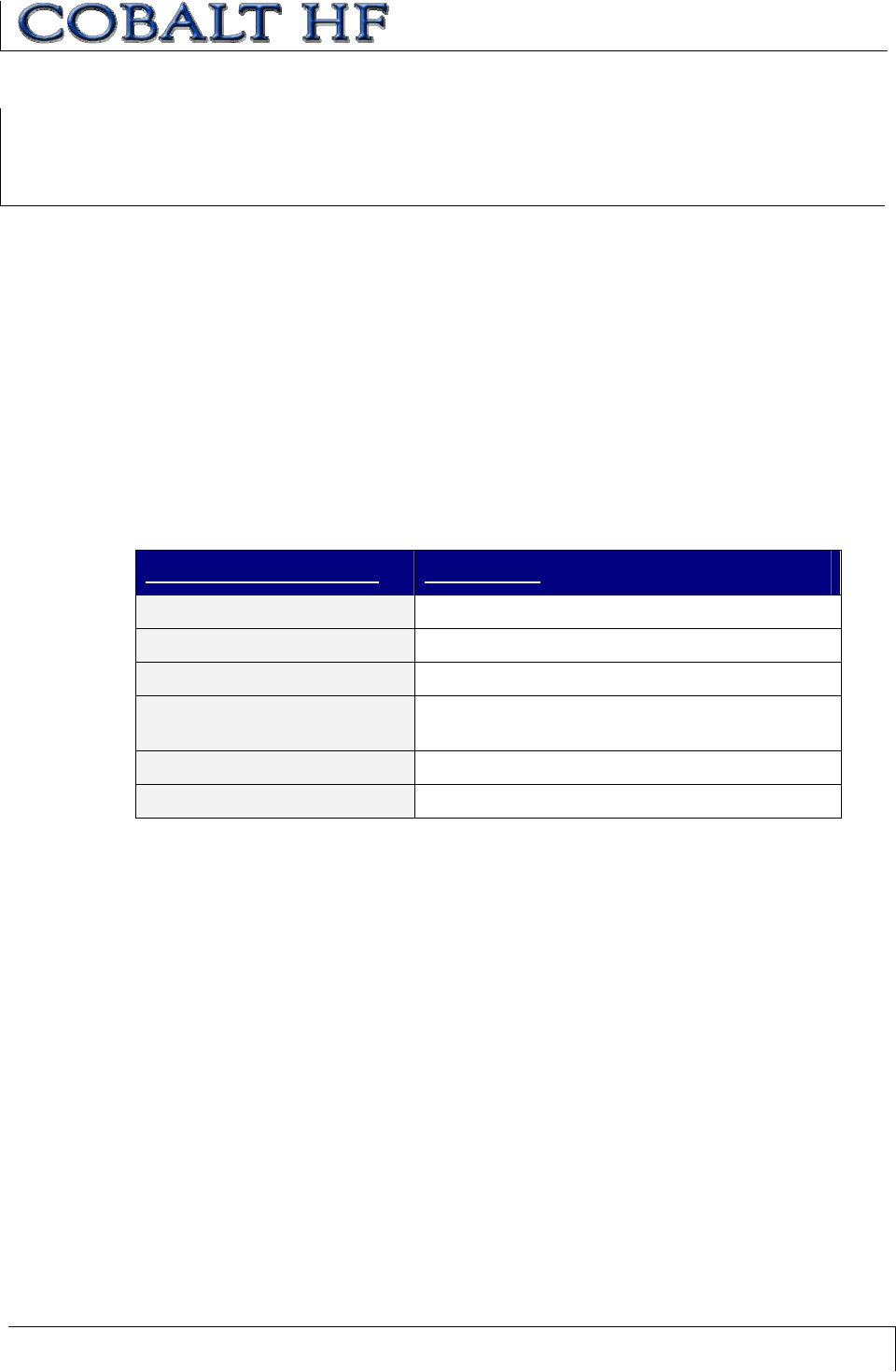
COMMAND 07 (READ TAG ID) – ABXFAST COMMAND STRUCTURE
PARAMETER FIELD CONTENT
Header 0x02, 0x02
Command Size 0x0003
Command ID 0x07
Timeout Value 2-byte value, measured in 1 millisecond units.
(0x0001 – 0xFFFE).
Checksum Optional
Terminator 0x03
COMMAND 07:
READ TAG ID
CHAPTER 7: RFID COMMANDS
COBALT HF RFID CONTROLLERS OPERATOR’S MANUAL
P/N: 17-1320 REV 01 (03-06) PAGE 81 OF 116
COMMAND 07 (READ TAG ID) – ABXFAST COMMAND EXAMPLE
This example instructs the controller to retrieve a tag’s ID. In this example, the 8-byte tag
ID number is E0040100002E16AD. A Timeout Value of two seconds is set for the
completion of this command.
Command from Host
PARAMETER FIELD CONTENT
Header 0x02, 0x02
Command Size 0x0003
Command ID 0x07
Timeout Value 0x07D0
Checksum Optional
Terminator 0x03
Response from Controller
PARAMETER FIELD CONTENT
Header 0x02, 0x02
Response Size 0x0009
Command Echo 0x07
Tag ID (bytes 1-8)0xE0 0x04 0x01 0x00 0x00 0x2E 0x16 0xAD
Checksum Optional
Terminator 0x03
CHAPTER 7: RFID COMMANDS
COBALT HF RFID CONTROLLERS OPERATOR’S MANUAL
P/N: 17-1320 REV 01 (03-06) PAGE 82 OF 116
COMMAND 07 (READ TAG ID) – CBXCOMMAND EXAMPLE
This example instructs the controller to retrieve a tag’s ID. In this example the 8-byte tag
ID number is E0040100002E16AD. A Timeout Value of 2 seconds is set for the
completion of this command.
Command from Host
PARAMETER FIELD MSB LSB
Overall Length of Command (in words)0x00 0x06
AA in MSB
Command ID in LSB (0x07)
0xAA 0x07
00 in MSB
Node ID in LSB (Cobalt –IND = 01)
0x00 0x01
2-byte Timeout Value measured in ms
(0x07D0 = 2 seconds)
0x07 0xD0
Not Used: (0x00, 0x00)0x00 0x00
Not Used: (0x00, 0x00)0x00 0x00
Response from Controller
PARAMETER FIELD MSB LSB
Overall Length of Response (in words)0x00 0x0A
AA in MSB
Command Echo in LSB
0xAA 0x07
00 in MSB
Node ID Echo in LSB
0x00 0x01
Month and Day timestamp Month DOM
Hour and Minute timestamp Hour Minutes
Seconds timestamp in MSB
Number of Tag ID Bytes Retrieved in LSB
(0x08)
Seconds 0x08
Tag ID (bytes 1 & 2)0xE0 0x04
Tag ID (bytes 3 & 4)0x01 0x00
Tag ID (bytes 5 & 6)0x00 0x2E
Tag ID (bytes 7 & 8)0x16 0xAD
CHAPTER 7: RFID COMMANDS
COBALT HF RFID CONTROLLERS OPERATOR’S MANUAL
P/N: 17-1320 REV 01 (03-06) PAGE 83 OF 116
Response if tag not found
PARAMETER FIELD MSB LSB
Overall Length of Response (in words)0x00 0x07
Error Flag in MSB
Command Echo in LSB
0xFF 0x07
00 in MSB
Node ID Echo in LSB
0x00 0x01
Month and Day timestamp Month DOM
Hour and Minute timestamp Hour Minutes
Seconds timestamp in MSB
# of Additional Data Bytes Retrieved in
LSB
Seconds 0x01
Error Code in MSB (0x07 = “Tag Not
Found Error”)
00 in LSB
0x07 0x00
CHAPTER 7: RFID COMMANDS
COBALT HF RFID CONTROLLERS OPERATOR’S MANUAL
P/N: 17-1320 REV 01 (03-06) PAGE 84 OF 116
Command 08 instructs the controller to search for the presence of a tag within RF range
of the antenna. If the controller finds a tag it will return a Command Response to the host.
The Timeout Value is measured in 1-millisecond increments and can have a value of
0x0001 to 0xFFFE (1 to 65,534 milliseconds).
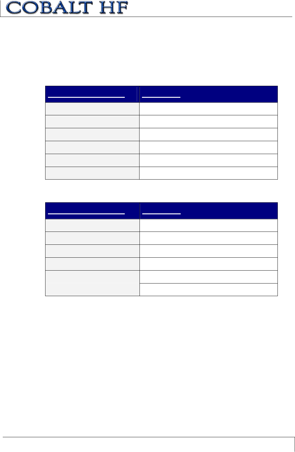
COMMAND 08 (TAG SEARCH)–ABXFAST COMMAND STRUCTURE
PARAMETER FIELD CONTENT
Header 0x02, 0x02
Command Size 0x0003 for this command
Command ID 0x08
Timeout Value 2-byte value measured in 1 millisecond units
(0x0001 – 0xFFFE).
Checksum Optional
Terminator 0x03
COMMAND 08:
TAG SEARCH
CHAPTER 7: RFID COMMANDS
COBALT HF RFID CONTROLLERS OPERATOR’S MANUAL
P/N: 17-1320 REV 01 (03-06) PAGE 85 OF 116
COMMAND 08 (TAG SEARCH)–ABXFAST COMMAND EXAMPLE
This example checks for an RFID tag within range of the antenna. The checksum is
enabled and the Timeout Value is set for 2 seconds (0x07D0 = 2000 milliseconds) for the
completion of this command.
Command from Host
PARAMETER FIELD CONTENT
Header 0x02, 0x02
Command Size 0x0003
Command ID 0x08
Timeout Value 0x07D0
Checksum 0x1D
Terminator 0x03
Response from Controller
PARAMETER FIELD CONTENT
Header 0x02, 0x02
Response Size 0x0001
Command Echo 0x08
Checksum 0xF6
Terminator 0x03
CHAPTER 7: RFID COMMANDS
COBALT HF RFID CONTROLLERS OPERATOR’S MANUAL
P/N: 17-1320 REV 01 (03-06) PAGE 86 OF 116
COMMAND 08 (TAG SEARCH)–CBXCOMMAND EXAMPLE
This command will instruct the controller to search for the presence of a tag within RF
range of the antenna.
Command from Host
PARAMETER FIELD MSB LSB
Overall Length of Command
(in words)
0x00 0x06
AA in MSB
Command ID in LSB (0x08)
0xAA 0x08
00 in MSB
Node ID in LSB (Cobalt = 1)
0x00 0x01
2-byte Timeout Value
measured in ms (0x07D0 = 2
seconds)
0x07 0xD0
Not Used: (0x00, 0x00)0x00 0x00
Not Used: (0x00, 0x00)0x00 0x00
Response from Controller
PARAMETER FIELD MSB LSB
Overall Length of Response
(in words)
0x00 0x06
AA in MSB
Command Echo in LSB
0xAA 0x08
00 in MSB
Node ID Echo in LSB
0x00 0x01
Month and Day timestamp Month DOM
Hour and Minute timestamp Hour Minutes
Seconds timestamp in MSB
00 in LSB
Seconds 0x00
CHAPTER 7: RFID COMMANDS
COBALT HF RFID CONTROLLERS OPERATOR’S MANUAL
P/N: 17-1320 REV 01 (03-06) PAGE 87 OF 116
Response if tag not found
PARAMETER FIELD MSB LSB
Overall Length of Response
(in words)
0x00 0x07
Error Flag in MSB
Command Echo in LSB
0xFF 0x08
00 in MSB
Node ID Echo in LSB
0x00 0x01
Month and Day timestamp Month DOM
Hour and Minute timestamp Hour Min
Seconds timestamp in MSB
Number of Additional Data
Bytes: 0x01
Seconds 0x01
Error Code in MSB (0x07 =
“Tag Not Found Error”)
00 in LSB
0x07 0x00
CHAPTER 7: RFID COMMANDS
COBALT HF RFID CONTROLLERS OPERATOR’S MANUAL
P/N: 17-1320 REV 01 (03-06) PAGE 88 OF 116
Command 0D instructs the controller to start (or stop) Continuous Read Mode.
When the Cobalt Controller is in Continuous Read Mode, it will constantly emit RF energy
in an attempt to read any tag that comes into range of the antenna. As a tag enters the
antenna field, it is immediately read and the data is passed to the host. The controller will
continue to read the tag but will not re-send the same data to the host until the tag has
moved outside the RF field for a specified time period. This parameter is known as the
Delay Between Duplicate Reads, which prevents redundant data transmissions when the
controller is in Continuous Read Mode.
If another RFID command is executed while the controller is in Continuous Read Mode,
the Cobalt HF will temporarily stop Continuous Reading to execute the command, after
which the controller will return to Continuous Read Mode.
The Start/Stop Continuous Read command contains three primary components: a Start
Address, aRead Length and a Delay Between Duplicate Reads value.
xStart Address: The Start Address is a 2-byte integer indicating the tag address
location where the read will begin.
xRead Length: The Read Length is a 2-byte integer that represents the number
of tag data bytes of retrieve. By setting this parameter to one (0x01) or higher,
Continuous Read Mode will be switched ON at the completion of the command.
Setting the Read Length to zero (0x00) will turn Continuous Read Mode off.
xDelay Between Duplicate Reads: During Continuous Read Mode, any tag that
comes within range of the antenna will be constantly read and the requested data
from the tag will be passed to the host. This single-byte delay parameter
indicates the number of seconds that a tag must remain out of RF range before it
can be re-read and have its data sent to the host for a second time. It is
implemented to enable the operator to limit the volume of information sent by the
controller. The Delay Between Duplicate Reads parameter can have a value of 0
to 60 seconds. When the Delay Between Duplicate Reads value is set to 0, the
controller will continuously read AND transmit duplicate tag data to the host.
Continuous Read at Power-up
By default, Continuous Read Mode is not restarted if the controller is reset. However,
through the use of the RFID Dashboard Utility, the Cobalt Controller can be configured
to enter Continuous Read Mode automatically after a reset or power-up. See Section 3.1
for more information regarding the RFID Dashboard Utility or visit: www.ems-rfid.com.
COMMAND 0D:
START/STOP CONTINUOUS READ
CHAPTER 7: RFID COMMANDS
COBALT HF RFID CONTROLLERS OPERATOR’S MANUAL
P/N: 17-1320 REV 01 (03-06) PAGE 89 OF 116
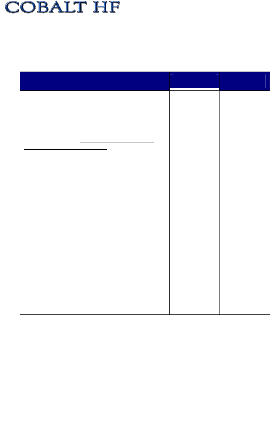
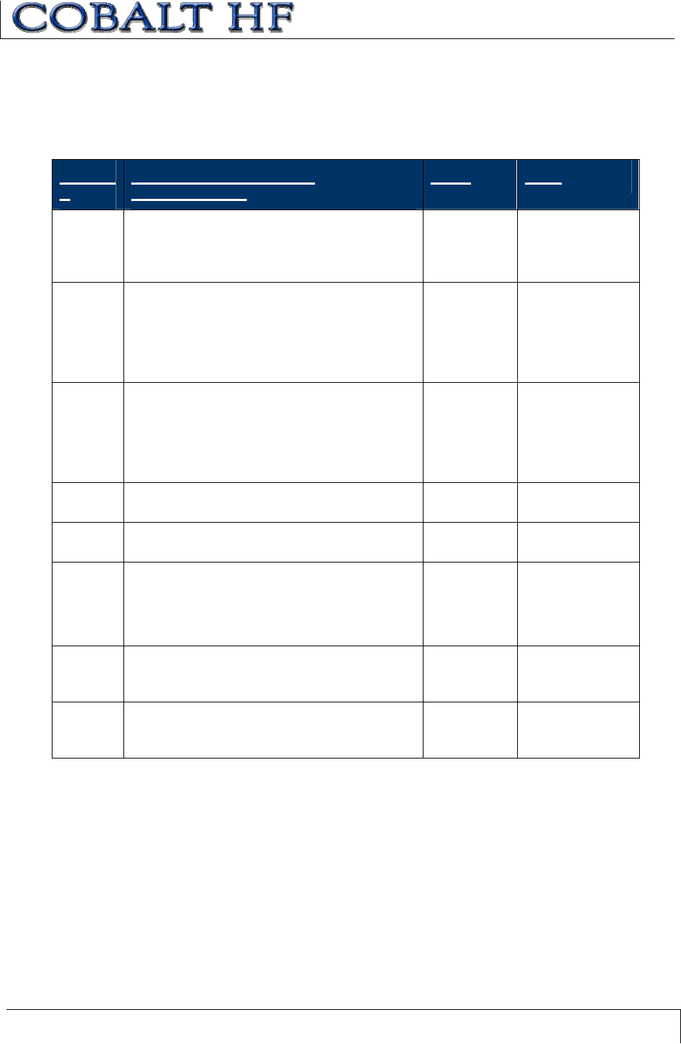
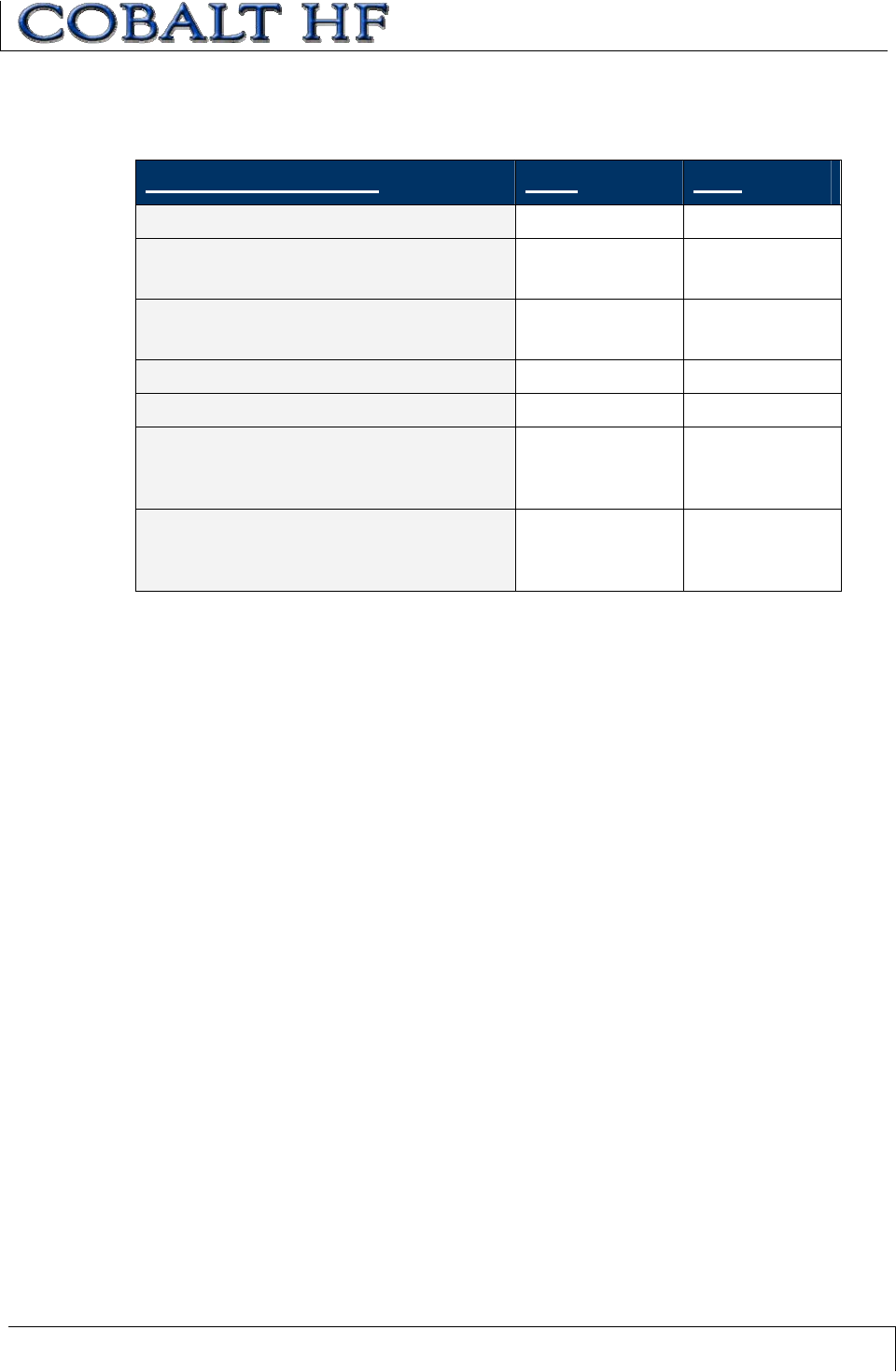
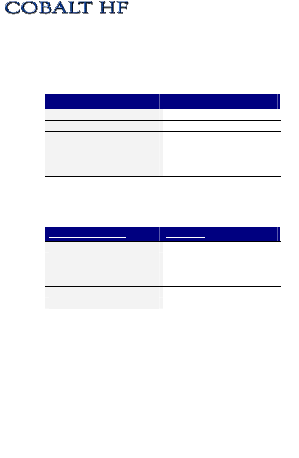
CONTINUOUS READ MODE LED BEHAVIOR
LED BEHAVIOR DESCRIPTION
PWR ON The controller is powered and functioning.
COM BLINKS ONCE Delay Between Duplicate Reads is set to 1 or
greater and a tag has entered the RF field.
COM BLINKING Delay Between Duplicate Reads is set to 0 and a
tag is in the RF field.
RF BLINKING Delay Between Duplicate Reads is set to 0 and a
tag is in the RF field.
RF BLINKS ONCE Delay Between Duplicate Reads is set to 1 or
greater and a tag has entered the RF field.
RF ON The controller is in Continuous Read Mode and no
tag is present.
Table 7-2: Continuous Read Mode - LED Behavior
COMMAND 0D (START/STOP CONTINUOUS READ)–
ABXFAST COMMAND STRUCTURE
PARAMETER FIELD CONTENT
Header 0x02, 0x02
Command Size 0x0006
Command ID 0x0D
Start Address 2-byte value for the tag address where the read
will start.
Read Length 2-byte value for number of bytes to be read.
Delay Between Duplicate
Reads
1-byte value for number of seconds a tag must
be out of RF range before the controller will re-
transmit data from same tag.
Checksum Optional
Terminator 0x03
CHAPTER 7: RFID COMMANDS
COBALT HF RFID CONTROLLERS OPERATOR’S MANUAL
P/N: 17-1320 REV 01 (03-06) PAGE 90 OF 116
COMMAND 0D (START/STOP CONTINUOUS READ)–
ABXFAST COMMAND EXAMPLE
This example places the controller in Continuous Read mode and reads four bytes of
data from the tag starting at address 0x0001. The Delay Between Duplicate Reads is set
to two seconds (0x02 = 2 x 1 second increments).
Starting Continuous Read - Command from Host
PARAMETER FIELD CONTENT
Header 0x02, 0x02
Command Size 0x0006
Command ID 0x0D
Start Address 0x0001
Read Length 0x0004
Delay Between Duplicate Reads 0x02
Checksum Optional
Terminator 0x03
Starting Continuous Read - Initial Response from Controller
PARAMETER FIELD CONTENT
Header 0x02, 0x02
Response Size 0x0001
Command Echo 0x0D
Checksum Optional
Terminator 0x03
CHAPTER 7: RFID COMMANDS
COBALT HF RFID CONTROLLERS OPERATOR’S MANUAL
P/N: 17-1320 REV 01 (03-06) PAGE 91 OF 116
Continuous Read Mode Evoked - Response from Controller (after Tag Read)
PARAMETER FIELD CONTENT
Header 0x02, 0x02
Response Size 0x0005
Command Echo 0x0D
Data from address 0x0001 0x05
Data from address 0x0002 0xAA
Data from address 0x0003 0xE7
Data from address 0x0004 0x0A
Checksum Optional
Terminator 0x03
To exit out of Continuous Read mode, issue Command 0D with zero (0x0000) in the
Read Length parameter field.
Stopping Continuous Read - Command from Host
PARAMETER FIELD CONTENT
Header 0x02, 0x02
Command Size 0x0006
Command ID 0x0D
Start Address 0x0001
Read Length 0x0000
Delay Between Duplicate Reads 0x02
Checksum Optional
Terminator 0x03
Stopping Continuous Read - Response from Controller
PARAMETER FIELD CONTENT
Header 0x02, 0x02
Response Size 0x0001
Command Echo 0x0D
Checksum Optional
Terminator 0x03
CHAPTER 7: RFID COMMANDS
COBALT HF RFID CONTROLLERS OPERATOR’S MANUAL
P/N: 17-1320 REV 01 (03-06) PAGE 92 OF 116
COMMAND 0D (START/STOP CONTINUOUS READ)–
CBXCOMMAND EXAMPLE
This example places the controller in Continuous Read Mode and reads 4 bytes of data
from the tag starting at address 0x0001. The Delay Between Duplicate Reads is set to 2
seconds (0x02 = 2 x 1 second increments).
Starting Continuous Read - Command from Host
PARAMETER FIELD MSB LSB
Overall Length of Command (in words)0x00 0x06
AA in MSB
Command ID in LSB (0x0D)
0xAA 0x0D
00 in MSB
Node ID in LSB (Cobalt -IND = 01)
0x00 0x01
00 in MSB
1-byte Delay Between Duplicate Reads
in LSB
0x00 0x02
Start Address 0x00 0x01
Read Length (in bytes)0x00 0x04
Starting Continuous Read - Initial Response from Controller
PARAMETER FIELD MSB LSB
Overall Length of Response (in words)0x00 0x06
AA in MSB
Command Echo in LSB
0xAA 0x0D
00 in MSB
Node ID Echo in LSB
0x00 0x01
Month and Day timestamp Month DOM
Hour and Minute timestamp Hour Min
Seconds timestamp in MSB
00 in LSB
Seconds 0x00
CHAPTER 7: RFID COMMANDS
COBALT HF RFID CONTROLLERS OPERATOR’S MANUAL
P/N: 17-1320 REV 01 (03-06) PAGE 93 OF 116
Continuous Read Mode Evoked - Response from Controller (after Tag Read)
PARAMETER FIELD MSB LSB
Overall Length of Response (in words)0x00 0x08
AA in MSB
Command Echo in LSB
0xAA 0x05
00 in MSB
Node ID Echo in LSB
0x00 0x01
Month and Day timestamp Month DOM
Hour and Minute timestamp Hour Minutes
Seconds timestamp in MSB
# of Bytes Read Data
Seconds 0x04
Read Data (bytes 1 & 2) 0x05 0xAA
Read Data (bytes 3 & 4) 0xE7 0x0A
To exit out of Continuous Read Mode, re-issue the command with zero (0x0000) for the
Read Length.
Stopping Continuous Read - Command from Host
PARAMETER FIELD MSB LSB
Overall Length of Command (in words)0x00 0x06
AA in MSB
Command ID in LSB (0x0D)
0xAA 0x0D
00 in MSB
Node ID in LSB (Cobalt = 01)
0x00 0x01
00 in MSB
1-byte Delay Between Duplicate Reads
in LSB
0x00 0x02
Start Address 0x00 0x00
Read Length (in bytes)0x00 0x00
CHAPTER 7: RFID COMMANDS
COBALT HF RFID CONTROLLERS OPERATOR’S MANUAL
P/N: 17-1320 REV 01 (03-06) PAGE 94 OF 116
Stopping Continuous Read - Response from Controller
PARAMETER FIELD MSB LSB
Overall Length of Response
(in words)
0x00 0x06
AA in MSB
Command Echo in LSB
0xAA 0x0D
00 in MSB
Node ID Echo in LSB
0x00 0x01
Month and Day timestamp Month DOM
Hour and Minute timestamp Hour Minutes
Seconds timestamp in MSB
00 in LSB
Seconds 0x00
CHAPTER 7: RFID COMMANDS
COBALT HF RFID CONTROLLERS OPERATOR’S MANUAL
P/N: 17-1320 REV 01 (03-06) PAGE 95 OF 116
Command 35 will cause the controller to cycle power - effectively rebooting the device -
without clearing any stored configuration information. Command 35 will reset the
controller’s configuration to default settings when a Configuration Tag is placed in the
antenna’s RF field prior to execution.
COMMAND 35 (RESET CONTROLLER)–ABXFAST COMMAND STRUCTURE
PARAMETER FIELD CONTENT
Header 0x02, 0x02
Command Size 0x0001
Command ID 0x35
Checksum optional
Terminator 0x03
COMMAND 35 (RESET CONTROLLER)–ABXFAST COMMAND EXAMPLE
This example resets power to the controller.
Command from Host
PARAMETER FIELD CONTENT
Header 0x02, 0x02
Command Size 0x0001
Command ID 0x35
Checksum Optional
Terminator 0x03
Response from Controller
PARAMETER FIELD CONTENT
Header 0x02, 0x02
Response Size 0x0001
Command Echo 0x35
Checksum Optional
Terminator 0x03
COMMAND 35:
RESET CONTROLLER
CHAPTER 7: RFID COMMANDS
COBALT HF RFID CONTROLLERS OPERATOR’S MANUAL
P/N: 17-1320 REV 01 (03-06) PAGE 96 OF 116
COMMAND 35 (RESET CONTROLLER)–CBXCOMMAND EXAMPLE
Command from Host
DESCRIPTION MSB LSB
Overall Length of Command
(in words)
0x00 0x06
AA in MSB
Command ID in LSB
0xAA 0x35
00 in MSB
Node ID in LSB
0x00 0x01
Not Used: (default: 0x00, 0x00)0x00 0x00
Not Used: (default: 0x00, 0x00)0x00 0x00
Not Used: (default: 0x00, 0x00)0x00 0x00
Response from Controller
DESCRIPTION MSB LSB
Overall Length of Response
(in words)
0x00 0x06
AA in MSB
Command Echo in LSB
0xAA 0x35
Instance Counter in MSB
Node Echo in LSB
Instance Counter 0x01
Month and Day timestamp Month Day
Hour and Minute timestamp Hour Min
Seconds timestamp in MSB
00 in LSB
Seconds 0x00
CHAPTER 7: RFID COMMANDS
COBALT HF RFID CONTROLLERS OPERATOR’S MANUAL
P/N: 17-1320 REV 01 (03-06) PAGE 97 OF 116
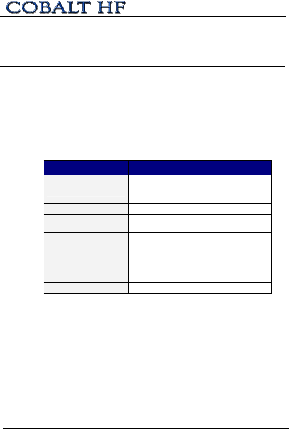
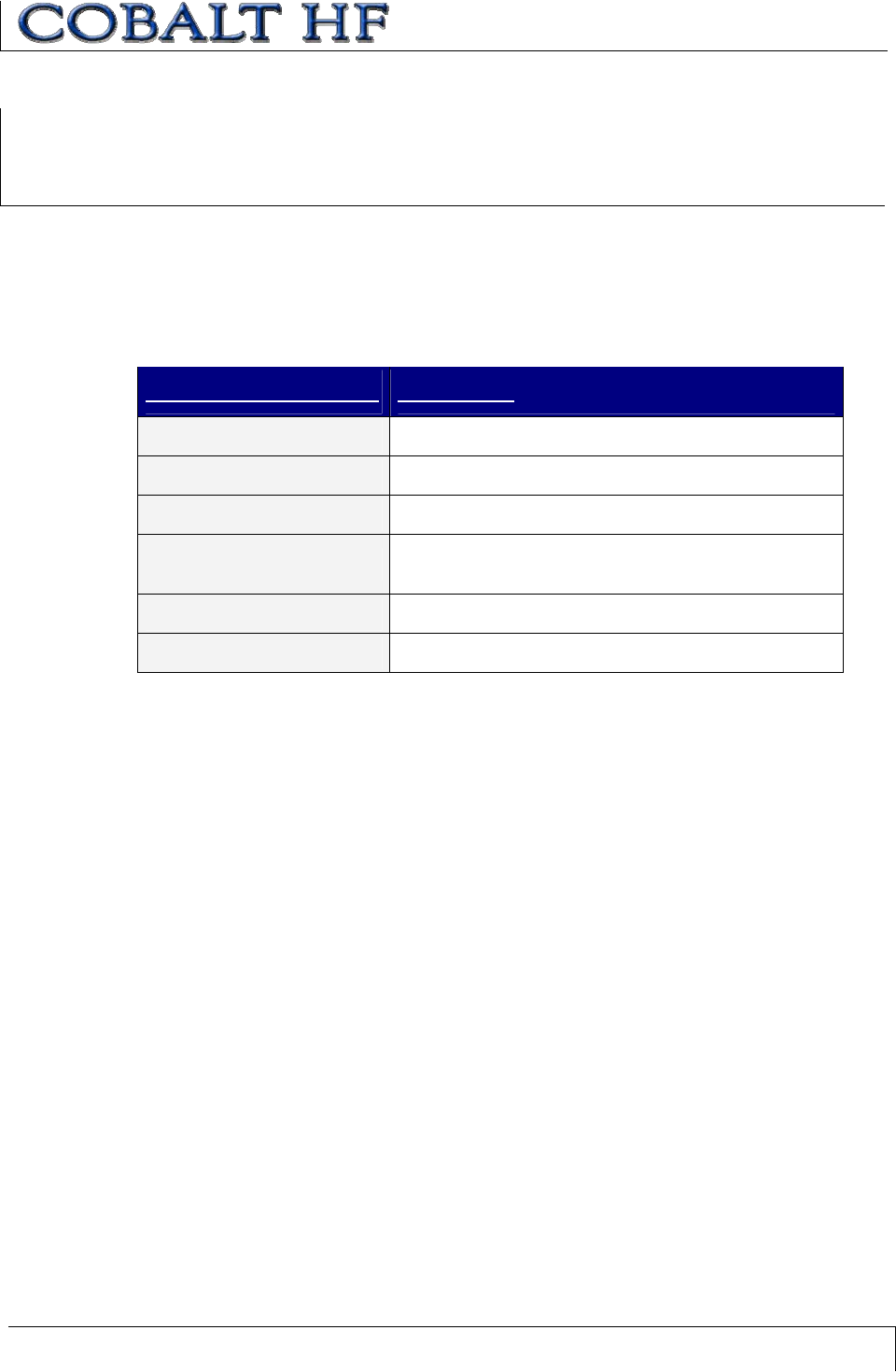
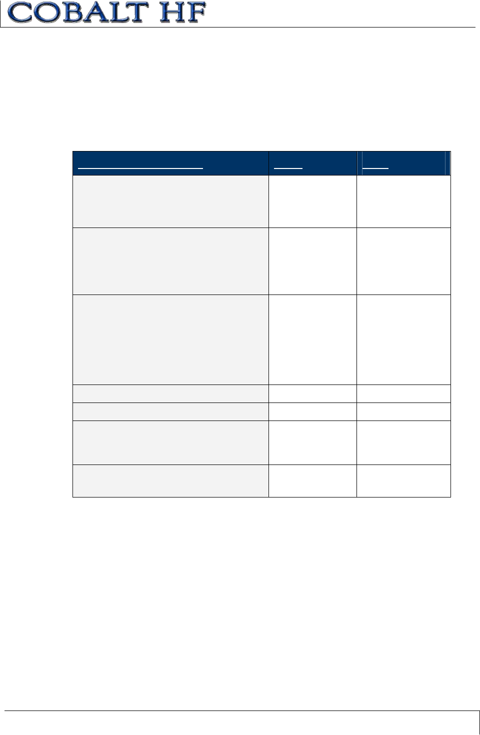
Command 38 is used to retrieve hardware version, serial number and installed firmware
identification information from the controller.
COMMAND 38 (GET CONTROLLER INFO)–
ABXFAST COMMAND STRUCTURE
PARAMETER FIELD CONTENT
Header 0x02, 0x02
Command Size 0x0001
Command ID 0x38
Checksum Optional
Terminator 0x03
COMMAND 38 (GET CONTROLLER INFO)–
ABXFAST COMMAND EXAMPLE
This example will query the Cobalt HF and retrieve specific internal hardware information.
Command from Host
PARAMETER FIELD CONTENT
Header 0x02, 0x02
Command Size 0x0001
Command ID 0x38
Checksum Optional
Terminator 0x03
COMMAND 38:
GET CONTROLLER INFO
CHAPTER 7: RFID COMMANDS
COBALT HF RFID CONTROLLERS OPERATOR’S MANUAL
P/N: 17-1320 REV 01 (03-06) PAGE 98 OF 116
Response from Controller
PARAMETER
FIELD
CONTENT DESCRIPTION CONTENT
SAMPLE
Header 2-byte Response Header (0x02, 0x02) 0x02, 0x02
Response Size 2-byte value for the total number of bytes in the
response packet, less Header, Command Size,
Checksum and Terminator bytes.
0x001B
Command Echo 0x38 0x38
RF Controller
Type
Controller Type default = 1 (0x01) 0x01
Major Release
Digit
The MAJOR release ASCII digit in the product
version number. Example product version
number: 0.0t.14.
Major Release Digit in this example = 0
0x30
Minor Release
Digit
The MINOR release ASCII digit in the product
version number. Example product version
number: 0.0t.14.
Minor Release Digit in this example = 0
0x30
Correction
Release Digit
The CORRECTION ASCII digit in the product
version number. Example product version
number: 0.0t.14.
Correction Release Digit in this example = t
0x74
Point Release
Digit
The POINT RELEASE digit in the product
version number. Example product version
number: 0.0t.14.
Point Release Digit in this example = 14
0x0E
Hardware
Version
Cobalt HF-xxx-01Hardware Version, default =
01 (0x01)
0x01
Block 0, 1, and 2
CRC
2-byte value for block 0, 1, and 2 CRC:
(example: 986E)
0x986E
Block 3, and 4
CRC
2-byte value for block 3, and 4 CRC: (example:
986E)
0x986E
RC632 ID 5-byte value for the RC632 ID:
(example: 30FFFF0F04)
0x30, 0xFF,
0xFF, 0x0F,
0x04
RC632 RFU 3-byte value for the RC632 RFU.
(example: 000000)
0x00, 0x00,
0x00
RC632 Serial
Number
4-byte value for the RC632 Serial Number.
(example: 05E19644)
0x05, 0xE1,
0x96, 0x44
RC632 Internal
Information
2-byte value for the RC632 internal.
(example: B669)
0xB669
CHAPTER 7: RFID COMMANDS
COBALT HF RFID CONTROLLERS OPERATOR’S MANUAL
P/N: 17-1320 REV 01 (03-06) PAGE 99 OF 116
RC632 RsMaxP Single-byte value for the RC632 RsMaxP:
(example: 65)
0x65
RC632
Information CRC
Single-byte value for the RC632 Information
CRC. (example: A6)
0xA6
Terminator 0x03 0x03
Controller Information (retrieved in the above example response)
RF Controller Type: 1
Product Version Number: 0.0T.5
Hardware Version: 01
Block 0, 1, and 2 CRC: 986E
Block 3, and 4 CRC: 986E
RC632 ID: 30FFFF0F04
RC632 RFU: 000000
RC632 Serial Number: 05E19644
RC632 internal: B669
RC632 RsMaxP: 65
RC632 Information CRC: A6
CHAPTER 7: RFID COMMANDS
COBALT HF RFID CONTROLLERS OPERATOR’S MANUAL
P/N: 17-1320 REV 01 (03-06) PAGE 100 OF 116
COMMAND 38 (GET CONTROLLER INFO)–CBXCOMMAND EXAMPLE
Command from Host
DESCRIPTION MSB LSB
Overall Length of Command 0x00 0x06
AA in MSB
Command ID in LSB (0x38:Get Controller
Info)
0xAA 0x38
0x00 in MSB
Node ID in LSB (Cobalt –IND = 01)
0x00 0x01
Not Used: (default: 0x00, 0x00)0x00 0x00
Not Used: (default: 0x00, 0x00)0x00 0x00
Not Used: (default: 0x00, 0x00)0x00 0x00
Response from Controller
DESCRIPTION MSB LSB
Overall Length of Response (in words)0x00 0x06 + number of
additional data
words retrieved
Command Echo 0xAA 0x38
Instance Counter in MSB
Node ID Echo in LSB
Instance
Counter
0x01
Month and Day timestamp Month Day
Hour and Minute timestamp Hour Min
Seconds timestamp in MSB
Number of Additional Data Bytes
Retrieved in LSB
Seconds N-bytes
Node Info: (bytes 1 & 2)Node Info -
byte 1
Node Info - byte 2
Node Info: (bytes 3 & 4) (…etc.) Node Info -
byte 3
Node Info - byte 4
CHAPTER 8: ERROR CODES
COBALT HF RFID CONTROLLERS OPERATOR’S MANUAL
P/N: 17-1320 REV 01 (03-06) PAGE 101 OF 116
CHAPTER 8:
ERROR CODES
If the Cobalt Controller encounters a fault during operation, the response that is
generated will include a 1-byte error code. Entering an invalid Start Address for a Read
Data command, for example, will generate Error Code 0x32 (Invalid Programming
Address).
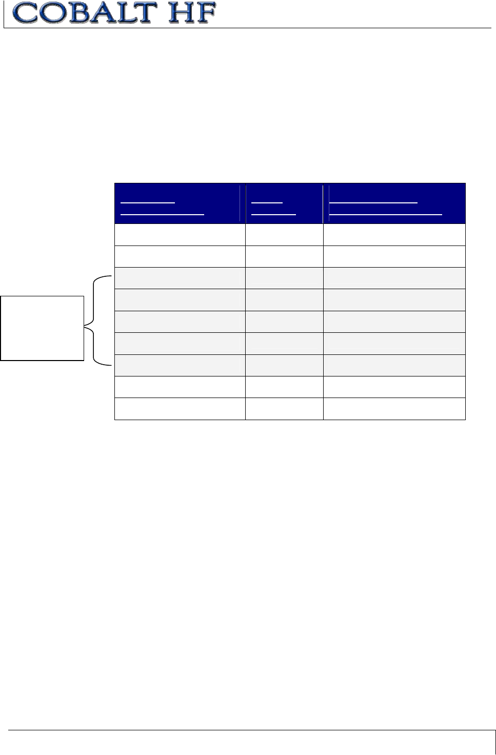
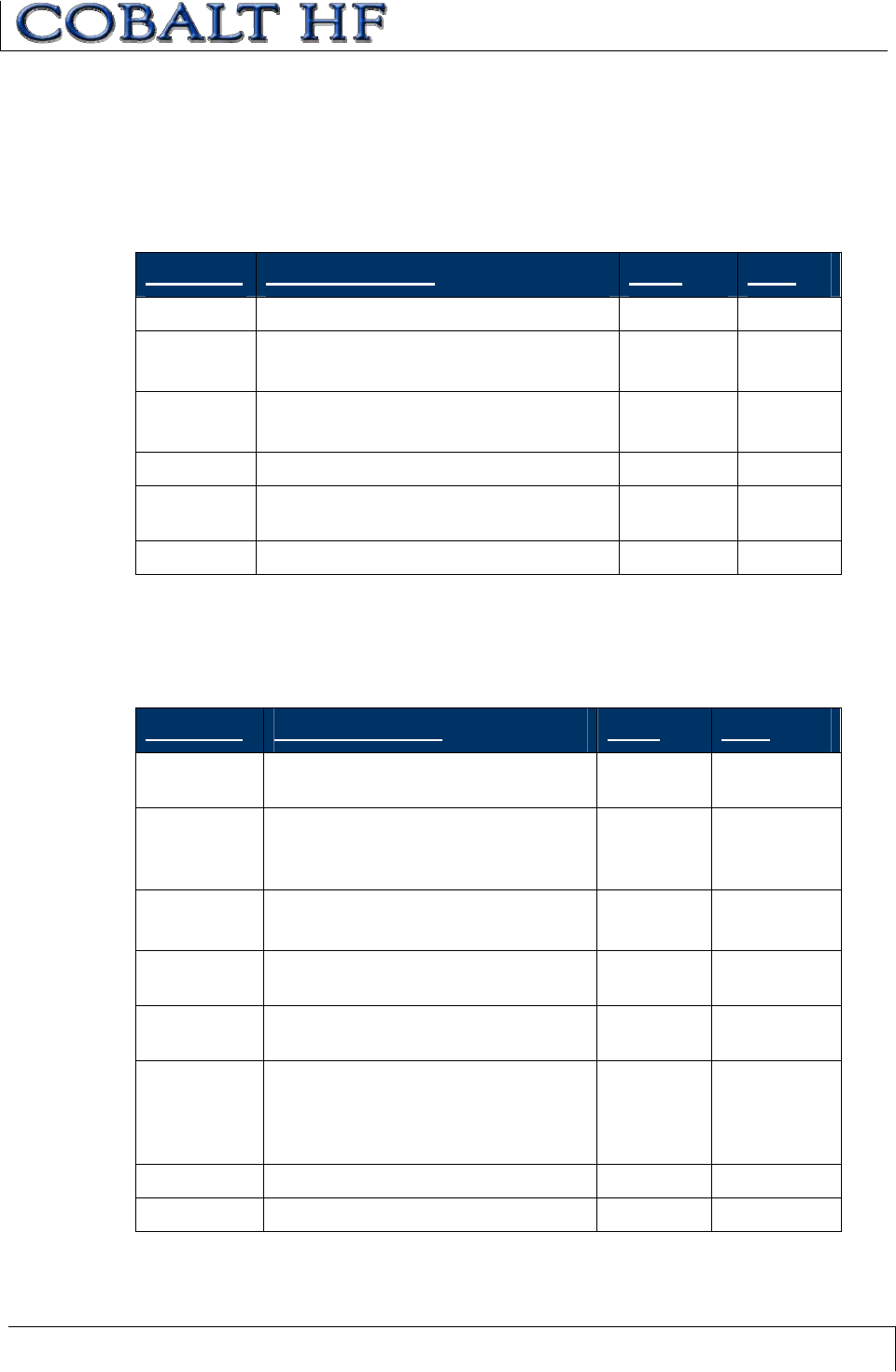
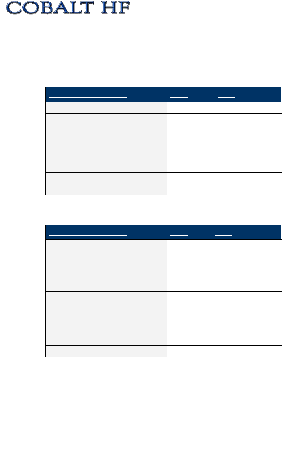
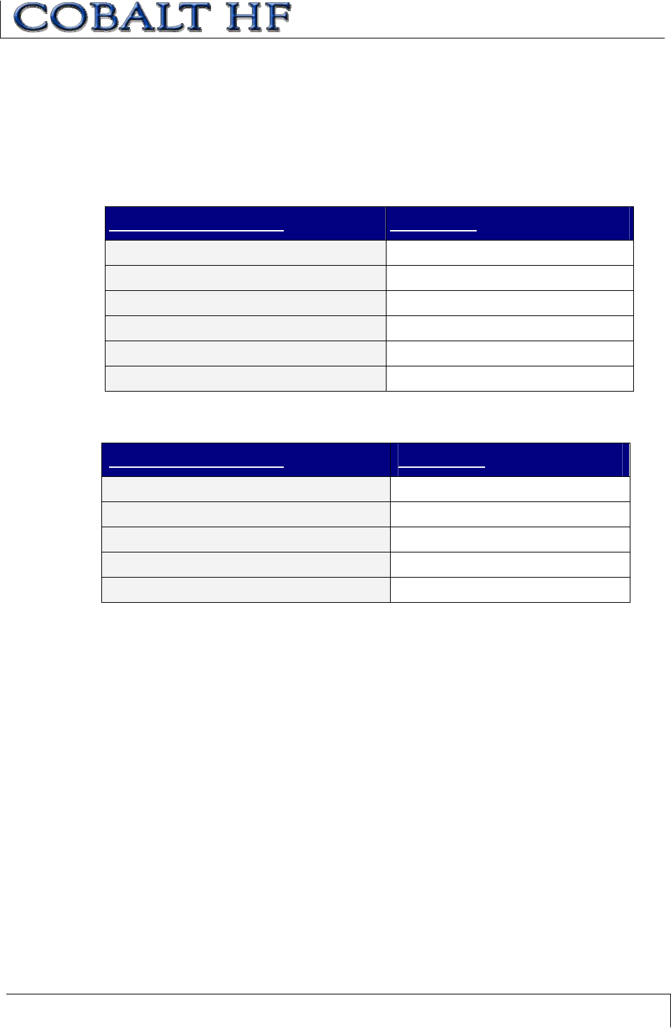
8.1 ERROR CODE TABLE
ERROR
CODE
ERROR NAME DESCRIPTION
0x04 FILL TAG FAILED Fill Operation Failed
0x05 READ DATA FAILED Read Data Command Failed
0x06 WRITE DATA FAILED Write Data Command Failed
0x07 READ TAG ID FAILED Read Tag ID Command Failed
0x08 TAG SEARCH FAILED Tag Search Command Failed / No
Tag Found
0x21 INVALID SYNTAX Command Contained a Syntax
Error
0x23 INVALID TAG TYPE Invalid or Unsupported Tag Type
0x30 INTERNAL CONTROLLER
ERROR
Generic Internal Controller Error
0x31 INVALID CONTROLLER TYPE Invalid Controller Type (when
Setting Configuration)
0x32 INVALID PROGRAMMING
ADDRESS
Invalid Tag Address Specified in
the Command
0x34 INVALID VERSION Invalid Software Version (when
Setting Configuration)
0x35 INVALID RESET Invalid Hardware Reset
0x36 SET CONFIGURATION
FAILED
Set Configuration Command Failed
0x37 GET CONFIGURATION
FAILED
Get Configuration Command Failed
0x83 COMMAND INVALID
OPCODE
An invalid Command ID number
was specified in the command.
0x84 COMMAND INVALID
PARAMETER
A parameter specified in the
command was invalid.
CHAPTER 8: ERROR CODES
COBALT HF RFID CONTROLLERS OPERATOR’S MANUAL
P/N: 17-1320 REV 01 (03-06) PAGE 102 OF 116
0x85 COMMAND INVALID
CONTROLLER ID
An invalid Node ID was specified in
the command, or no controller was
detected/present at the specified
Node.
0x86 COMMAND INACTIVE
CONTROLLER ID
The Node ID specified in the
command is currently inactive.
0x87 SUBNET DEVICE SELECT
FAILED
Internal Subnet Error – the
specified Subnet device failed.
0x88 SUBNET DEVICE FAILED TO
ACKNOWLEDGE
Internal Subnet Error - the
specified Subnet device failed to
respond to the Hub’s polling.
0x89 SUBNET RESPONSE
MALFORMED
Internal Subnet Error – a controller
returned a malformed response.
0x8A SUBNET RESPONSE
TIMEOUT
Internal Subnet Error – a controller
was unable to generate a response
before timeout was reached.
0x8B SUBNET RESPONSE
INVALID CHECKSUM
Internal Subnet Error – a controller
generated a response that has an
invalid checksum.
0x8C SUBNET DEVICE CONFLICT
DETECTED
Internal Subnet Error – a Node ID
conflict has been detected
0x8D BUFFER OVERFLOW Internal Error – buffer limit was
exceeded
0x8E FLASH FAILURE Internal Error – flash memory
failure
0x92 SUBNET16 ONLY
COMMAND
A Subnet16-only command was
issued when in MUX32 mode.
0x93 MODBUS NODE MISMATCH
ERROR
The Node specified in the
command did not match the Node
to which the command was sent
(MUX32 mode).
0x94 MODBUS CRC ERROR Internal Communications Error
(MUX32 mode)
0x95 MODBUS PROTOCOL
ERROR
Internal Communications Error
(MUX32 mode)
Table 8-1: Error Code Table
CHAPTER 8: ERROR CODES
COBALT HF RFID CONTROLLERS OPERATOR’S MANUAL
P/N: 17-1320 REV 01 (03-06) PAGE 103 OF 116
8.2 ABXFAST:
ERROR RESPONSE PACKET STRUCTURE
For any ABx Fast error response, a single-byte Error Code always follows the 0xFF byte
(Error Flag byte).
PARAMETER FIELD CONTENT
Header 0x02, 0x02
Response Size 0x0002
Error Flag 0xFF
Error Code 1-byte error code
Checksum optional
Terminator 0x03
Table 8-2: ABx Fast - Error Response Structure
ABXFAST -ERROR RESPONSE EXAMPLE
Below is an example of an ABx Fast error response (with checksum) for a failed Write
Data command (error code 0x06).
PARAMETER FIELD CONTENT
Header 0x02, 0x02
Response Size 0x0002
Error Flag 0xFF
Error Code 0x06
Checksum 0xF8
Terminator 0x03
CHAPTER 8: ERROR CODES
COBALT HF RFID CONTROLLERS OPERATOR’S MANUAL
P/N: 17-1320 REV 01 (03-06) PAGE 104 OF 116
8.3 CBXPROTOCOL:
ERROR RESPONSE PACKET STRUCTURE
A one-byte Error Code will be returned in the MSB of the seventh data word in the error
response packet (followed by a zero - 0x00 in the LSB).
PARAMETER FIELD MSB LSB
Overall Length: 2-byte value indicating
the number of “words” in the Response
Packet. This value will always be at least
7words (6 + 1 for the error code).
0x00 0x07
Error Flag Byte: 0xFF in the MSB
indicates that an error occurred.
Command ID Echo: 1-byte value in the
LSB indicates the command that was
attempted when the error occurred.
0xFF Command ID
Echo
Instance Counter: This 1-byte value
tallies the number of responses from a
given Node ID.
Node ID: 1-byte value in LSB indicates
the Node ID of the controller that
experienced or generated the error.
(Cobalt -IND = 01)
Instance Counter 0x01
Month and Day timestamp Month Day
Hour and Minute timestamp Hour Minute
Seconds timestamp in MSB
# of Additional Bytes Retrieved in LSB
(0x01 for error responses).
Seconds 0x01
Error Code: 1-byte Error Code in MSB
00 in LSB
Error Code 0x00
Table 8-3: CBx Error Response Structure
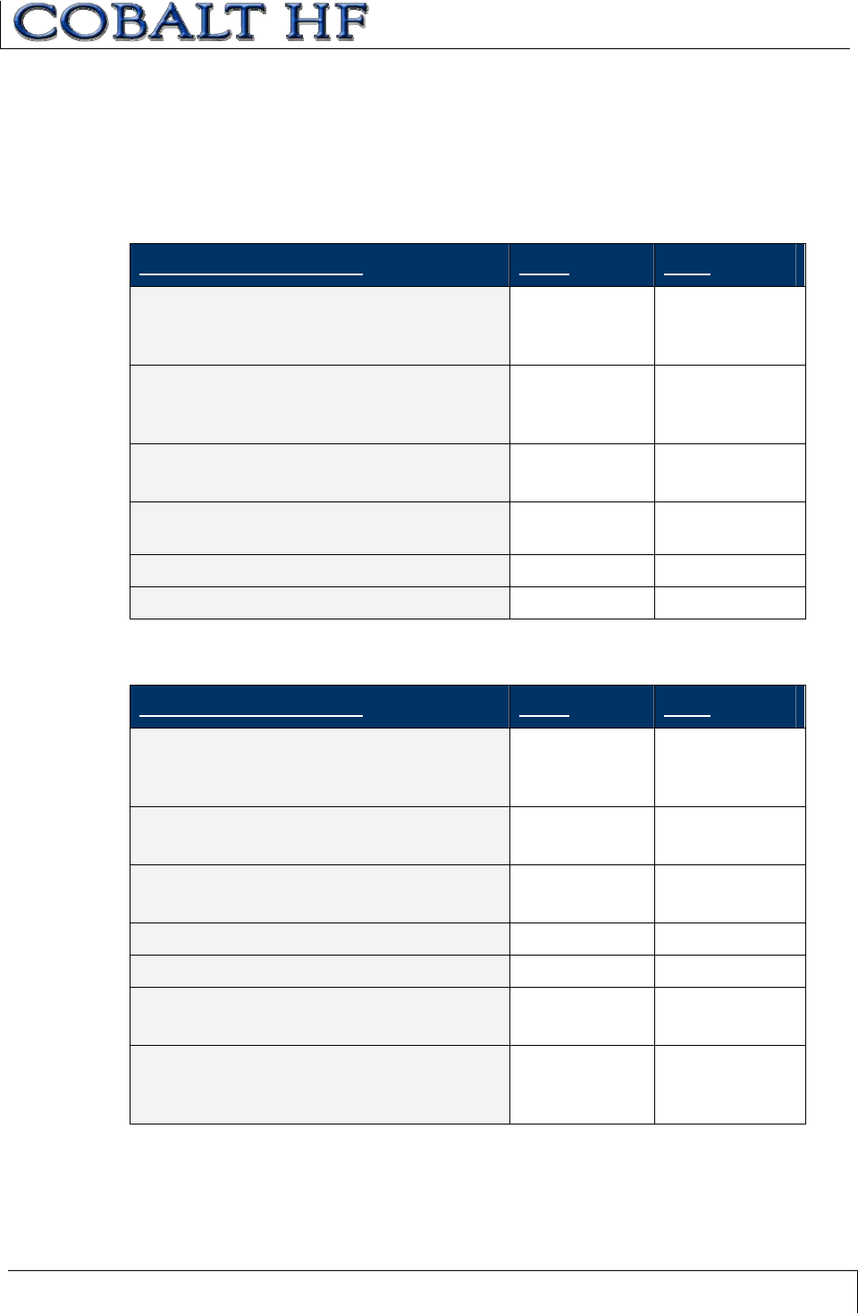
CHAPTER 8: ERROR CODES
COBALT HF RFID CONTROLLERS OPERATOR’S MANUAL
P/N: 17-1320 REV 01 (03-06) PAGE 105 OF 116
CBX-ERROR RESPONSE EXAMPLE
Below is an example of a CBx error response (error code 0x08) for a failed Tag Search
(Command ID: 0x08).
Command from Host
PARAMETER FIELD MSB LSB
00 in MSB
Overall Length of Command in LSB
(in words)
0x00 0x06
AA in MSB
Command ID in LSB:
(0x08 – Tag Search)
0xAA 0x08
00 in MSB
Node ID in LSB (Cobalt –IND = 01)
0x00 0x01
2-byte Timeout Value measured in ms:
(0x07D0 = 2 seconds)
0x07 0xD0
Not Used: (0x00, 0x00)0x00 0x00
Not Used: (0x00, 0x00)0x00 0x00
Error Response (if no tag is found)
PARAMETER FIELD MSB LSB
00 in MSB
Overall Length of Response in LSB
(in words)
0x00 0x07
Error Flag in MSB
Command Echo in LSB
0xFF 0x08
00 in MSB
Node ID Echo in LSB
0x00 0x01
Month and Day timestamp Month DOM
Hour and Minute timestamp Hour Minutes
Seconds timestamp in MSB
# of Additional Data Bytes: (0x01)
Seconds 0x01
Error Code in MSB:
(0x08 = “Tag Search Failed”)
00 in LSB
0x08 0x00
APPENDIX A:
COBALT HF SPECIFICATIONS
COBALT HF RFID CONTROLLERS OPERATOR’S MANUAL
P/N: 17-1320 REV 01 (03-06) PAGE 106 OF 116
APPENDIX A:
COBALT HF SPECIFICATIONS
ELECTRICAL
Supply Voltage: 10~30VDC
Power Consumption: 12W (450mA @ 24VDC)
COMMUNICATION
Communication Interfaces: x Point-to-Point: RS232, RS422, USB
x Multi-drop: Subnet16 (RS485)
x Ethernet: Ethernet/IP, Modbus TCP,
TCP/IP
RFID Interface: Cobalt HF-Series RFID System
RF Output Power: 1W
Air Protocols: IǜCODE 1, ISO 15693, ISO 14443 A
Air Protocol Speed: 26.5kBaud/106kBaud with CRC error
detection
RS232/RS422/485 Baud Rates: 9600 (default), 19.2k, 38.4k, 57.6k, 115.2k
MECHANICAL
Dimensions: Refer to Chapter 1, Section 1.4
Weight: .44 KG (1 lb. – 440 grams)
Enclosure: Powder-Coated Aluminum
ENVIRONMENTAL
Operating Temperature: -20° to 50°C (-4° to 122°F),
Storage Temperature: -40° to 85°C (-40° to 185°)
Humidity: 100%
Protection Class: IP66
Shock Resistance: IEC 68-2-27 Test EA 30g, 11milliseconds,
3 shocks each axis
Vibration Resistance IEC 68-2-6 Test FC 1.5mm; 10 to 55Hz;
2 hours each axis
APPENDIX B:
MODELS & ACCESSORIES
COBALT HF RFID CONTROLLERS OPERATOR’S MANUAL
P/N: 17-1320 REV 01 (03-06) PAGE 107 OF 116
APPENDIX B:
MODELS & ACCESSORIES
COBALT HF RFID CONTROLLER MODELS
There are five models of the Cobalt HF RFID Controller:
HF-CNTL-232-01 – for RS232 interface connections
HF-CNTL-422-01 – for RS422 interface connections
HF-CNTL-485-01 – for RS485 interface connections
HF-CNTL-USB-01 – for USB interface connections
HF-CNTL-IND-01 – for Industrial Ethernet interface connections
COBALT HF ANTENNA MODELS
There are four models of the Cobalt HF Antenna:
HF-ANT-1010-01 – 10cm x 10cm
HF-ANT-2020-01 – 20cm x 20cm
HF-ANT-3030-01 – 30cm x 30cm
HF-ANT-0750-01 – 7cm x 50cm (for conveyor applications)
SUBNET16 GATEWAYS
GWY-01-TCP-01
Subnet16™ TCP/IP Gateway – for commercial TCP/IP environments
GWY-01-IND-01
Subnet16™ Industrial Ethernet Gateway – for Industrial Ethernet environments
SUBNET16 HUBS
HUB-04-TCP-01
Subnet16™ TCP/IP Hub (4-port) – for commercial TCP/IP environments
HUB-04-IND-01
Subnet16™ Industrial Ethernet Hub (4-port) – for Industrial Ethernet environments
APPENDIX B:
MODELS & ACCESSORIES
COBALT HF RFID CONTROLLERS OPERATOR’S MANUAL
P/N: 17-1320 REV 01 (03-06) PAGE 108 OF 116
POWER SUPPLIES
00-1166: 24VDC, 1.88A max, 45W, Universal Input (90-264VAC, 47-63Hz), 5.5x2.5mm
plug, positive tip; Note: Requires country specific power cord to mate to IEC 320 power
cord receptacle.
00-1167: 24VDC, 4.17A max, 100W, Universal Input (90-264VAC, 47-63Hz), 5.5x2.5mm
plug, positive tip; Note: Requires country specific power cord to mate to IEC 320 power
cord receptacle.
00-1168: 24VDC, 5.0A max, 120W, Universal Input (88-132VAC/176-264VAC switch
selectable, 47-63Hz) DIN Rail Mount; Note: AC wire receptacles are spring clamp for
direct wire connection.
COBALT HF SOFTWARE APPLICATIONS
RFID Dashboard:provides users with complete control over their Escort Memory
Systems RFID system. The RFID Dashboard allows system operators to configure,
monitor and control Cobalt HF-Series RFID devices from anywhere on their network.
C-MacroBuilder:an easy to use GUI-driven utility that allows users to create, edit and
save powerful RFID macros.
Cobalt HF-SDK: Cobalt HF Controller - Software Development Kit (requires Microsoft®
Visual Studio® .Net). Contact your distributor.
Visit the Escort Memory Systems website (www.ems-rfid.com) for download instructions.
APPENDIX B:
MODELS & ACCESSORIES
COBALT HF RFID CONTROLLERS OPERATOR’S MANUAL
P/N: 17-1320 REV 01 (03-06) PAGE 109 OF 116
COBALT CABLES &CONNECTORS
CBL-1478 - RS232 Cable with DB9 Female Plug and 2.5mm DC Jack
CBL-1480-0.2 - Male/Female, ThinNet Drop Cable, 0.2m
CBL-1480-02 - Male/Female, ThinNet Drop Cable, 2m
CBL-1480-10 - Male/Female, ThinNet Drop Cable, 10m (for Hubs only)
CBL-1481-0.2 - Male/Male, ThinNet Drop Cable, 0.2m
CBL-1481-01 - Male/Male, ThinNet Drop Cable, 1m
CBL-1481-02 - Male/Male, ThinNet Drop Cable, 2m (Gateway to T)
CBL-1482-02 - Male/90 Degree Female, ThinNet Drop, Cable, 2m
CBL-1482-10 - Male/90 Degree Female, ThinNet Drop, Cable, 10m
CBL-1483 - Male/Female, ThickNet Trunk Cable, 10m
CBL-1484 - Female w/ Bare Wire, ThickNet Trunk Cable, 2m
CBL-1485 - ThickNet to ThinNet Drop-T
CBL-1486 - ThinNet to ThinNet Drop-T
CBL-1487 – Straight Female M12 Field Mountable Connector
CBL-1488 - M12-8, Female w/ Bare Wires Cable, 2m, (-232- & -422)
CBL-1489 - Male 7/8-16 ThickNet 120-Ohm Termination Resistor Plug
CBL-1490 - Male M12 ThinNet 120-Ohm Termination Resistor Plug
CBL-1491 - 90 Degree Female M12 Field Mountable Connector
CBL-1492 - M12-8, 90 Degree Female w/ Bare Wires Cable, 2m, (-232 & -422)
CBL-1493 - M12-8, Straight Female Field Mountable Connector
CBL-1513 – M12, 5-Pin, Male, Reverse Keyed to Type A, USB Cable 3M
CBL-1514 – M12, 5-Pin, Straight Male, Reverse Keyed Connector for USB
CBL-1515-05 – Cable, Ethernet/M12, 5-Pin, Male, D-Code, 5M
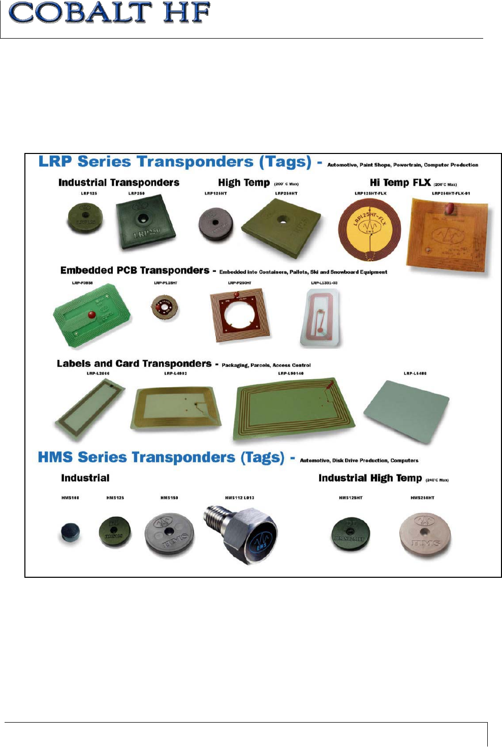
APPENDIX B:
MODELS & ACCESSORIES
COBALT HF RFID CONTROLLERS OPERATOR’S MANUAL
P/N: 17-1320 REV 01 (03-06) PAGE 110 OF 116
RFID TAGS
Escort Memory Systems designs and manufactures several lines of RFID tags. LRP and
HMS-Series passive read/write RFID tags are specially suited for the Cobalt HF Series
product line.

APPENDIX C:
NETWORK DIAGRAMS
COBALT HF RFID CONTROLLERS OPERATOR’S MANUAL
P/N: 17-1320 REV 01 (03-06) PAGE 111 OF 116
APPENDIX C:
NETWORK DIAGRAMS
x Cobalt Ethernet Network
x Subnet16 Gateway ThickNet Network
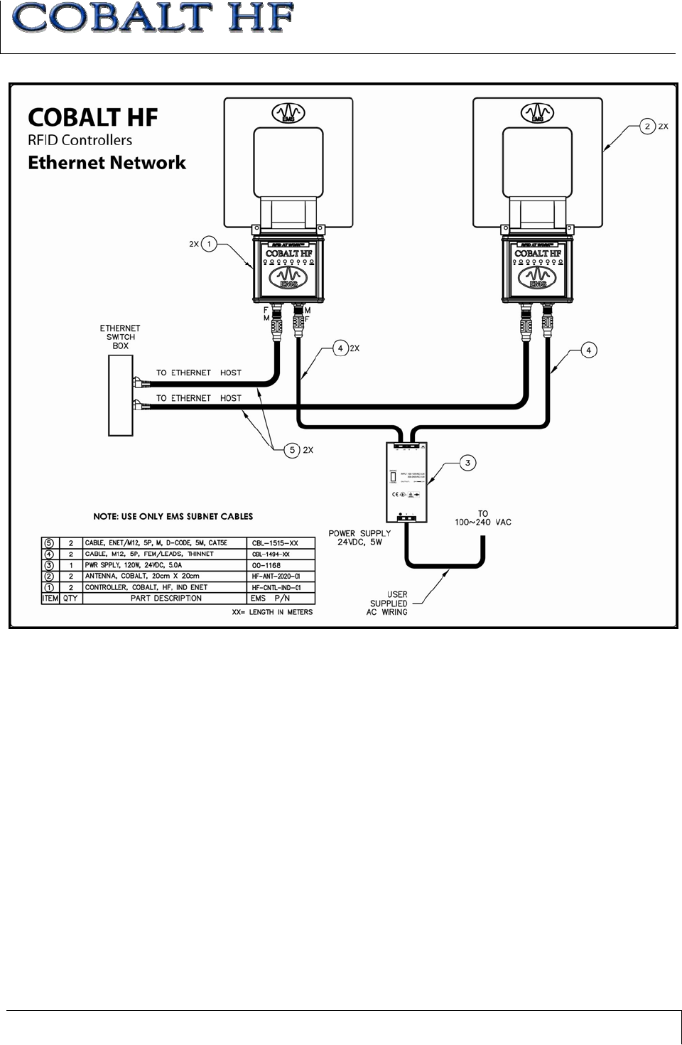
APPENDIX C:
NETWORK DIAGRAMS
COBALT HF RFID CONTROLLERS OPERATOR’S MANUAL
P/N: 17-1320 REV 01 (03-06) PAGE 112 OF 116
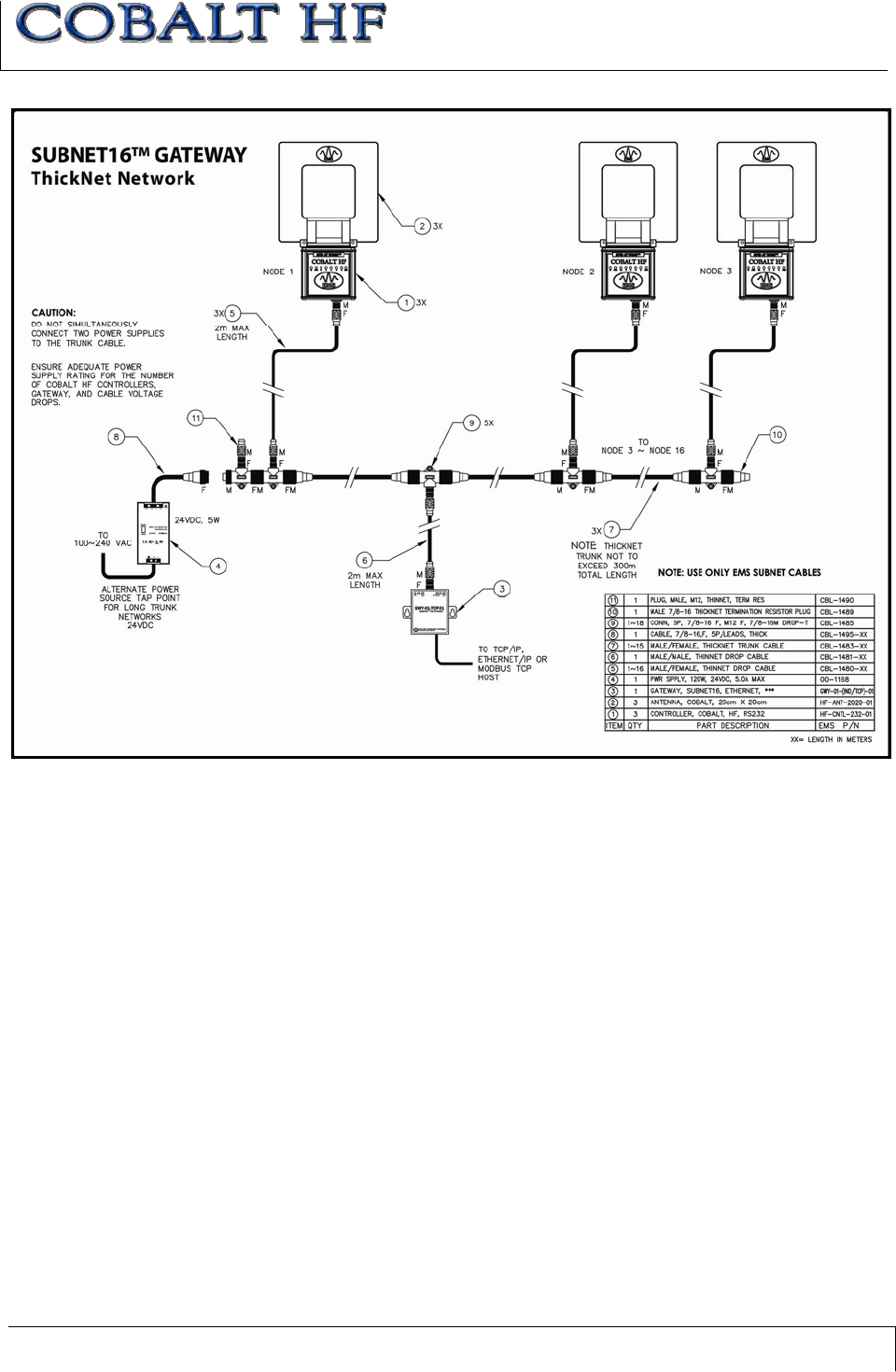
APPENDIX C:
NETWORK DIAGRAMS
COBALT HF RFID CONTROLLERS OPERATOR’S MANUAL
P/N: 17-1320 REV 01 (03-06) PAGE 113 OF 116
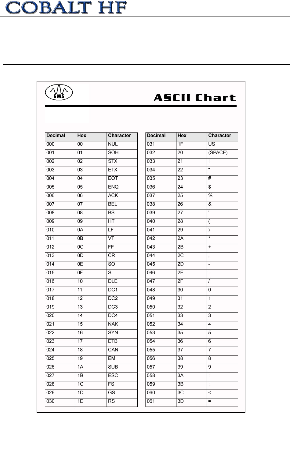
APPENDIX D: ASCII CHART
COBALT HF RFID CONTROLLERS OPERATOR’S MANUAL
P/N: 17-1320 REV 01 (03-06) PAGE 114 OF 116
APPENDIX D:
ASCII CHART
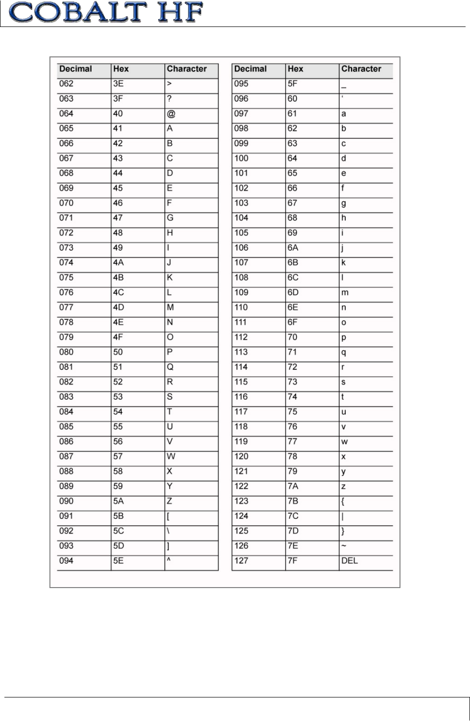
APPENDIX D: ASCII CHART
COBALT HF RFID CONTROLLERS OPERATOR’S MANUAL
P/N: 17-1320 REV 01 (03-06) PAGE 115 OF 116
WARRANTY
COBALT HF RFID CONTROLLERS OPERATOR’S MANUAL
P/N: 17-1320 REV 01 (03-06) PAGE 116 OF 116
WARRANTY
scort Memory Systems warrants that all products of its own manufacturing
conform to Escort Memory Systems’ specifications and are free from defects in
material and workmanship when used under normal operating conditions and
within the service conditions for which they were furnished. The obligation of Escort
Memory Systems hereunder shall expire one (1) year after delivery, unless otherwise
specified, and is limited to repairing, or at its option, replacing without charge, any such
product which in Escort Memory Systems’ sole opinion proves to be defective within the
scope of this Warranty. In the event Escort Memory Systems is not able to repair or
replace defective products or components within a reasonable time after receipt thereof,
Buyers shall be credited for their value at the original purchase price. Escort Memory
Systems must be notified in writing of the defect or nonconformity within the warranty
period and the affected product returned to Escort Memory Systems factory or to an
authorized service center within thirty (30) days after discovery of such defect or
nonconformity. Shipment shall not be made without prior authorization by Escort Memory
Systems.
This is Escort Memory Systems' sole warranty with respect to the products delivered
hereunder. No statement, representation, agreement or understanding oral or written,
made by an agent, distributor, representative, or employee of Escort Memory Systems
which is not contained in this warranty, will be binding upon Escort Memory Systems,
unless made in writing and executed by an authorized Escort Memory Systems
employee.
Escort Memory Systems makes no other warranty of any kind what so ever, expressed or
implied, and all implied warranties of merchantability and fitness for a particular use which
exceed the aforementioned obligation are here by disclaimed by Escort Memory Systems
and excluded from this agreement. Under no circumstances shall Escort Memory
Systems be liable to Buyer, in contract or in tort, for any special, indirect, incidental, or
consequential damages, expenses, losses or delay however caused. Equipment or parts
which have been subject to abuse, misuse, accident, alteration, neglect, unauthorized
repair or installation are not covered by warranty. Escort Memory Systems shall make the
final determination as to the existence and cause of any alleged defect. No liability is
assumed for expendable items such as lamps and fuses. No warranty is made with
respect to equipment or products produced to Buyer’s specification except as specifically
stated in writing by Escort Memory Systems in the contract for such custom equipment.
This warranty is the only warranty made by Escort Memory Systems with respect to the
goods delivered hereunder, and may be modified or amended only by a written
instrument signed by a duly authorized officer of Escort Memory Systems and accepted
by the Buyer.
Extended warranties of up to four years are available for purchase for most Escort
Memory Systems products. Contact Escort Memory Systems or your distributor for more
information.
E