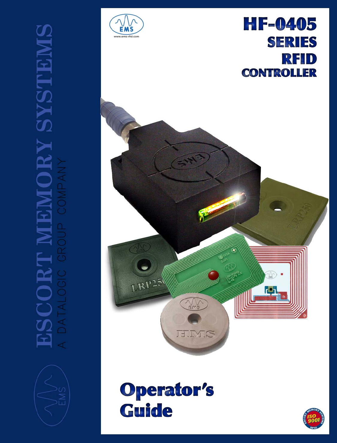
Balluff HF-0405-XXX-01 Passive RFID Reader/Writer User Manual Part I

BALLUFF inc Passive RFID Reader/Writer Users Manual Part I

Contents

Users Manual Part I

  HF-0405 RFID Controller  Passive High Frequency Radio Frequency Identification Controller    Operator’s Guide         How to Install, Configure and Operate  Escort Memory Systems’ HF-0405  RFID Controllers               HF-0405 RFID Controller Models: • HF-0405-232-01 • HF-0405-422-01 • HF-0405-485-01    HF-0405-232/422/485-01 – Radio Frequency Identification Controller – Operator’s Guide. Part No: 17-1303 Rev 1.A
 3   Escort Memory Systems Warranty Escort Memory Systems warrants that all products of its own manufacturing conform to Escort Memory Systems’ specifications and are free from defects in material and workmanship when used under normal operating conditions and within the service conditions for which they were furnished. The obligation of Escort Memory Systems hereunder shall expire one (1) year after delivery, unless otherwise specified, and is limited to repairing, or at its option, replacing without charge, any such product which in Escort Memory Systems’ sole opinion proves to be defective within the scope of this Warranty. In the event Escort Memory Systems is not able to repair or replace defective products or components within a reasonable time after receipt thereof, Buyers shall be credited for their value at the original purchase price. Escort Memory Systems must be notified in writing of the defect or nonconformity within the warranty period and the affected product returned to Escort Memory Systems factory or to an authorized service center within thirty (30) days after discovery of such defect or nonconformity. Shipment shall not be made without prior authorization by Escort Memory Systems. This is Escort Memory Systems' sole warranty with respect to the products delivered hereunder. No statement, representation, agreement or understanding oral or written, made by an agent, distributor, representative, or employee of Escort Memory Systems which is not contained in this warranty, will be binding upon Escort Memory Systems, unless made in writing and executed by an authorized Escort Memory Systems employee.  Escort Memory Systems makes no other warranty of any kind what so ever, expressed or implied, and all implied warranties of merchantability and fitness for a particular use which exceed the aforementioned obligation are here by disclaimed by Escort Memory Systems and excluded from this agreement. Under no circumstances shall Escort Memory Systems be liable to Buyer, in contract or in tort, for any special, indirect, incidental, or consequential damages, expenses, losses or delay however caused. Equipment or parts which have been subject to abuse, misuse, accident, alteration, neglect, unauthorized repair or installation are not covered by warranty. Escort Memory Systems shall make the final determination as to the existence and cause of any alleged defect. No liability is assumed for expendable items such as lamps and fuses. No warranty is made with respect to equipment or products produced to Buyer's specification except as specifically stated in writing by Escort Memory Systems in the contract for such custom equipment. This warranty is the only warranty made by Escort Memory Systems with respect to the goods delivered hereunder, and may be modified or amended only by a written instrument signed by a duly authorized officer of Escort Memory Systems and accepted by the Buyer.  Extended warranties of up to four years are available for purchase for most Escort Memory Systems products. Contact Escort Memory Systems or your distributor for more information. Escort Memory Systems reserves the right to make modifications or improvements without prior notification. Escort Memory Systems shall not be liable for technical or editorial errors or omissions contained herein, nor for incidental or consequential damages resulting from the use of this material. Product names mentioned herein are for identification purposes only and may be trademarks and or registered trademarks of their respective companies. Escort Memory Systems™ and the Escort Memory Systems logo are registered trademarks of Escort Memory Systems, a Datalogic Group Company.  Copyright © 2004-2005 Escort Memory Systems   ALL RIGHTS RESERVED
 Table Of Contents  5   Table of Contents TABLE OF CONTENTS.............................................................................................5 CHAPTER 1 ● GETTING STARTED ........................................................................9 Introduction ...................................................................................................................... 9 Our Background........................................................................................................................... 9 The HF-0405 RFID Controller .....................................................................................................9 HF-0405 Features ........................................................................................................... 10 FCC and CE Compliance Notice ............................................................................................... 11 About this Guide ............................................................................................................ 11 About this Guide ............................................................................................................ 12 HEX Notation ............................................................................................................................. 12 Who Should Read this Guide? .................................................................................................. 12 How this Guide is Organized .....................................................................................................13 Unpacking and Inspecting the HF-0405 .......................................................................14 Contents of the HF-0405 Package ............................................................................................ 15 User Supplied Components....................................................................................................... 15 Product and Document Versions.................................................................................. 16 Controller Model Number and Hardware Version ..................................................................... 16 Operator’s Guide Document Revision Number ......................................................................... 16 Updating the HF-0405 Firmware ................................................................................... 17 Downloading the Latest Updates............................................................................................... 17 RFID Demonstration Utility ........................................................................................................ 17 Customer Applications..................................................................................................18 RFID Strategy & Case Studies .................................................................................................. 18 CHAPTER 2 ● HARDWARE DESCRIPTION .........................................................21 Dimensions and Diagrams ............................................................................................ 21 Installation and Mounting Guidelines .......................................................................... 22 RFID Installation Checklist......................................................................................................... 22 Know Your Application Requirements ....................................................................................... 22 Antenna Environment ................................................................................................................ 23 Mounting the HF-0405............................................................................................................... 24 Words of Caution ....................................................................................................................... 24 RFID Tags .......................................................................................................................25 Overview.................................................................................................................................... 25 Tag Embodiments...................................................................................................................... 27 Tag Memory............................................................................................................................... 28 Tag Memory Map....................................................................................................................... 29 Memory Optimization................................................................................................................. 29 ISO 1443A/B.............................................................................................................................. 31 ISO 15693.................................................................................................................................. 31 ISO 18000-3.1 ........................................................................................................................... 31
 Table Of Contents  6   CHAPTER 3 ● POWER & COMMUNICATION CONFIGURATION........................32 Power Requirements...................................................................................................... 32 Warning about “Hotplugging”.....................................................................................................32 Serial Interface Options.................................................................................................33 HF-0405 Model Numbers and Supported Serial Interface Protocols ........................................ 33 RS232 Interface Connection ..................................................................................................... 34 RS422 Interface Connection ..................................................................................................... 34 RS485 Interface Connection ..................................................................................................... 34 Making Connections ...................................................................................................... 35 Connecting the HF-0405 to the Host ......................................................................................... 35 COM Port Configuration ................................................................................................ 35 COM Port Parameter Options ................................................................................................... 35 Pinouts ............................................................................................................................ 36 HF-0405-232/422 Pinouts .........................................................................................................36 HF-0405-485 Pinouts................................................................................................................. 36 HF-0405-485 Pinouts................................................................................................................. 37 The Configuration Tag ................................................................................................... 38 Configuration Tag Overview ......................................................................................................38 Configuration Tag Memory Map ................................................................................................ 38 Using the Configuration ............................................................................................................. 38 CHAPTER 4 ● LED STATUS .................................................................................39 Normal LED Operation Functions................................................................................. 39 LED Descriptions ........................................................................................................... 40 HF-0405-232 LED Status ..........................................................................................................41 HF-0405-422 LED Status ..........................................................................................................41 HF-0405-485 LED Status ..........................................................................................................42 Special LED Operation Functions ............................................................................................. 44 Error Conditions......................................................................................................................... 46 CHAPTER 5 ● COMMUNICATION PROTOCOLS .................................................47 Communication Overview ............................................................................................. 47 ABx Command Protocols .............................................................................................. 47 ABx Command Structures ......................................................................................................... 48 ABx Response Structures.......................................................................................................... 48 ABx Command Parameters....................................................................................................... 49 ABx Fast Command Protocol .................................................................................................... 51 ABx ASCII Command Protocol.................................................................................................. 53 ABx Standard Command Protocol............................................................................................. 58 CHAPTER 6 ● RFID COMMANDS .........................................................................60 RFID Command Table .................................................................................................... 60 Command 04 ◘ (0x04): Tag Fill................................................................................................. 61
 Table Of Contents  7   Command 05 ◘ (0x05): Read Data ........................................................................................... 64 Command 06 ◘ (0x06): Write Data............................................................................................ 67 Command 07 ◘ (0x07): Read Tag ID (SN)................................................................................ 70 Command 08 ◘ (0x08): Tag Search .......................................................................................... 73 Command 0D ◘ (0x0D): Start/Stop Continuous Read .............................................................. 76 Command 0A ◘ (0x0A): Set RS232/422 Baud Rate ................................................................. 82 Command 36 ◘ (0x36): Send Controller Configuration ............................................................. 84 Command 37 ◘ (0x37): Read Controller Configuration............................................................. 86 Command 38 ◘ (0x38): Read Controller SN ............................................................................. 88 Command A1 ◘ (0xA1): Reset Controller.................................................................................. 90 CHAPTER 7 ● ABX ERROR CODES.....................................................................91 ABx Error Code Table .................................................................................................... 91 ABx Fast Error Response Structure............................................................................. 92 ABx ASCII Error Response Structure........................................................................... 93 ABx Standard Error Response Structure..................................................................... 94 CHAPTER 8 ● TROUBLESHOOTING....................................................................95 HF-0405 Troubleshooting Table.................................................................................... 95 Contact Technical Support............................................................................................ 95 APPENDIX A ● SPECIFICATIONS .........................................................................96 HF-0405 Data Sheet........................................................................................................96 Technical Specifications ............................................................................................... 97 APPENDIX B ● MODELS AND ACCESSORIES ....................................................98 HF-0405-232-01 ............................................................................................................... 98 HF-0405-422-01 ............................................................................................................... 98 HF-0405-485-01 ............................................................................................................... 98 HF-0405 Compatible Accessories ............................................................................................. 99 APPENDIX C ● ASCII CHART ..............................................................................100 APPENDIX D ● RFID TERMINOLOGY & DEFINITIONS ......................................101 INDEX……………………………………………………………………………………..107
 Table Of Contents  8      www.ems-rfid.com
 Chapter 1: Getting Started 9   Chapter 1 ● Getting Started This chapter contains an introduction to Escort Memory Systems and includes general information relating to the HF-0405 RFID Controller and common uses for RFID technology.  Introduction Welcome to the HF-0405 Series RFID Controller Operator’s Guide. This guide will assist you in the installation, configuration and operation of Escort Memory Systems’ HF-0405 Series RFID Controllers. The HF-0405 Series is a complete line of passive high frequency read/write Radio-Frequency Identification solutions. They are designed to be compact, reliable and rugged, and though they measure only 56mm x 40mm, the HF-0405 RFID Controllers are highly integrated with everything you will need to start benefiting from RFID technology.  Our Background Since 1985, Escort Memory Systems has been an industry leader in providing Radio Frequency Identification (RFID) devices and has built a solid reputation by consistently delivering an extended selection of quality, durable industrial RFID systems. Today, Escort Memory Systems continues to deliver a complete line of high performance, industrial RFID equipment, including the HF-0405 Series RFID Controller.  The HF-0405 RFID Controller Escort Memory Systems' HF-0405 Series RFID Controllers are the latest in our line of passive RFID controllers that utilize the Radio Frequency (RF) field from the controller’s integrated antenna to power RFID enabled tags. By being able to receive power from the RFID controller, the tag, itself, does not need a battery and is said to be “passive”.  Passive tags must enter the antenna’s electromagnetic field to establish a radio link which allows for the transfer of information through inductive coupling. The HF-0405 uses the internationally recognized ISM frequency
 Chapter 1: Getting Started 10   of 13.56 MHZ to power the tag and then modulates side-band frequencies to communicate.  The HF-0405 system provides cost effective RFID data collection and control solutions to shop floor, item-level tracking, and material handling applications.  The entire RFID system works by attaching a tag (or transponder) to a product or its carrier which acts as an electronic identifier, portable job sheet, or real-time tracking database. Tags are identified, read and written to by issuing specific commands to the HF-0405 RFID Controller from the Host.  Tags can be read and/or written to (which is sometimes referred to as “interrogating the tag”) through any nonconductive, non-metallic material, while moving or standing still, in or out of the direct line of sight. The HF-0405 series RFID Controller is compatible with all LRP and HMS Series tags from Escort Memory Systems. The HF-0405 can also communicate with ISO 14443 and ISO 15693 tags from other manufacturers.  Escort Memory Systems uses error checking routines that ensure that the RFID controller receives tag data correctly even in environments with heavy RF interference. LED indicators on the RFID controller provide continuous real-time feedback on the status of the unit. (See Chapter 5, for more information regarding LED status). HF-0405 Features •  Supports for multiple high performance RF, ABx, air and serial communications protocols. •  13.56 megahertz RFID Controller with integrated antenna. •  Compact size (approximately 4cm X 5.5cm). •  Flash memory for software updates. •  Auto configurable / Software programmable •  Eight LED status indicator lights. •  Reads/Writes ISO 14443A/B and ISO 15693 compatible RFID tags •  Reads/Writes existing LRP and HMS Series tags from Escort Memory Systems •  90% backward compatible with Escort Memory Systems  HMS827, HMS828, LRP75 RFID Controllers  •  FCC/CE/ARIB T-82 Agency compliance certified
 Chapter 1: Getting Started 11   FCC and CE Compliance Notice FCC Part 15.105 This equipment has been tested and found to comply with the limits for a Class B digital device, pursuant to part 15 of the FCC Rules. These limits are designed to provide reasonable protection against harmful interference in a residential installation. This equipment generates, uses and can radiate radio frequency energy and, if not installed and used in accordance with the instructions, may cause harmful interference to radio communications. However, there is no guarantee that interference will not occur in a particular installation. If this equipment does cause harmful interference to radio or television reception, which can be determined by turning the equipment off and on, the user is encouraged to try to correct the interference by one or more of the following measures: •  Reorient or relocate the receiving antenna. •  Increase the separation between the equipment and receiver.  •  Connect the equipment into an outlet on a circuit different from that to which the receiver is connected.  •  Consult the dealer or an experienced radio/TV technician for help. FCC Part 15.21  Users are cautioned that changes or modifications to the unit not expressly approved by Escort Memory Systems may void the user's authority to operate the equipment.  This device complies with Part 15 of the FCC Rules. Operation is subject to the following two conditions: (1) This device may not cause harmful interference, and (2) this device must accept any interference that may cause undesired operation.”  This product complies with CFR Title 21 Part 15.225, EN-300-330, EN-300-683, TELEC, EN 60950, IEC 68-2-1, IEC 68-2-6, IEC 68-2-27, IEC 68-2-28.
 Chapter 1: Getting Started 12   About this Guide This document provides guidelines and instructions on how to install and operate the HF-0405 Series RFID Controllers. Also included are descriptions of the RFID command set with instructions describing how to issue commands to the HF-0405 Series RFID Controllers. Occasionally throughout this guide, we refer to the HF-0405 RFID Controller as the HF-0405, the HF-0405 Controller or just simply the RFID controller.   HEX Notation In this guide, numbers expressed in Hexadecimal notation are prefaced with “0x”. For example, the number of fingers on a typical person is expressed as "10" in decimal or as "0x0A" in hexadecimal. See Appendix C for a chart containing Hex values, ASCII characters and their corresponding decimal integers. Who Should Read this Guide? This guide should be read by those who will be installing, configuring and operating the HF-0405 RFID Controller. This may include the following people:  • Hardware Installers • System Integrators • Project Managers • IT Personnel • System and Database Administrators • Software Application Engineers • Service and Maintenance Engineers    We have attempted to make this guide as simple and straightforward as possible. Where ever possible, we will attempt to explain and demystify RFID for you.
 Chapter 1: Getting Started 13   How this Guide is Organized •  The opening chapter in this guide describes the basic features and functionality of the HF-0405 RFID Controller. You will also find customer case studies and background information necessary for understanding RFID. Chapter 1 ● Getting Started •  Chapters 2-4 discuss the configuration of your RFID environment and provide information relating to the actual functionality, installation and setup of the HF-0405 and the configuration of your RFID environment.  Chapter 2 ● Hardware Description Chapter 3 ● Power & Communication Configuration Chapter 4 ● LED Status • Chapter 5 talks about communication protocols and ABx command protocols.  Chapter 5 ● Communication Protocols • Chapter 6 contains a detailed listing of the RFID commands supported by the HF-0405.  Chapter 6 ● RFID Commands • Chapter 7 will help you recognize and interpret ABx and RFID error codes.  Chapter 7 ● ABx Error Codes • If you are having problems or need Technical Support see Ch. 8. Chapter 8 ● Troubleshooting • Lastly, you will want to familiarize your self with the back of this document. There you will find several Appendix sections designed to provide additional technical assistance and reference information.  Appendix A ● Specifications Appendix B ● Models and Accessories Appendix C ● ASCII Chart  Appendix D ● RFID Terminology & Definitions
 Chapter 1: Getting Started 14   Unpacking and Inspecting the HF-0405 Unpack the HF-0405 hardware and accessories. Retain the original shipping carton and packing material in case any items need to be returned. Inspect each item carefully for evidence of damage. If an item appears to be damaged, notify your distributor immediately.
 Chapter 1: Getting Started 15   Contents of the HF-0405 Package The HF-0405 Series RFID Controller product package contains the following components: •  HF-04050 Series RFID Controller • Mounting Bracket •  2 screws (M4-20 PPH SS 18-8\302)  •  2 nuts (M4 SS 18-8\302) •  HF-0405 Series Configuration Tag Mounting Bracket Each HF-0405 Controller ships with an L-shaped polycarbonate mounting bracket and the necessary hardware required to mount the controller to the mounting bracket. Configuration Tag Each HF-0405 RFID Controller is shipped with a unique configuration tag. The configuration tag contains manufacturing data regarding the controller and can be used to restore the controller’s factory defaults in the event that serial communications become programmed to an unknown state. For the HF-0405-485 model, the configuration tag can be used to manually set the Subnet16™ node address. The configuration tag is a 112-byte ISO15693 compliant RFID tag that has had most of its memory addresses locked at the factory to prevent important data from being overwritten. However, for testing and demonstration purposes, certain addresses of the configuration tag have not been locked and can be written to. We recommend storing the configuration tag in a safe location in case the need arises to use it. Refer to Chapter 3 for more information regarding the use of the configuration tag. User Supplied Components The User Must Supply the Following Components: •  Host computer or Programmable Logic Controller (PLC) with an RS232, RS422 or TCP/IP serial interface connection •  DC Power Source supplying 10~30 Voltage DC, with an Operating Range of 180mA and a Surge Current of 250mA.    Escort Memory Systems approved RS232, RS422 or RS485 compatible serial communications cable (See Appendix B, for cables and accessories) Also, have plenty of HF-0405 Series compliant Passive Read/Write Tags available for testing and system integration.   Plan to have the user supplied items tested and running prior to the installation of your HF-0405 RFID Controller.
 Chapter 1: Getting Started 16   Product and Document Versions Controller Model Number and Hardware Version There are three versions of the HF-0405 RFID Controller, each designed to support specific serial interface requirements. The model number and supported serial interface connections are listed below: The HF-0405-232-01 supports RS232 Serial Interface. The HF-0405-422-01 supports RS422 Serial Interface. The HF-0405-485-01 supports RS485 Serial Interface. RS232 will support cable lengths up to 15m for point-to-point Host/Controller connections. RS422 will support cable lengths up to 50m for point-to-point Host/Controller connections (provided adequate gauge cabling is used for power and signals). RS485 supports Subnet16™ Multidrop bus architecture and protocol, allowing for up to 16 connection nodes on one bus connected through a Subnet16 Gateway. For more information on model numbers, parts and accessories for all HF-0405 Series RFID Controllers see Appendix B: Models & Accessories. Operator’s Guide Document Revision Number This is the original publication of Escort Memory Systems’ HF-0405 Series RFID Controller – Operator’s Guide. It coincides with the initial release of the HF-0405 Series Controllers. Document No. 17-1303 Revision 1.A  HF-0405-232/422/485 - High Frequency Passive Radio Frequency Identification Controller – Operator’s Guide.
 Chapter 1: Getting Started 17   Updating the HF-0405 Firmware Downloading the Latest Updates The operating system for the HF-0405 is stored in flash memory in the form of firmware on an EEPROM chip. Occasionally, Escort Memory Systems will release firmware updates (and its revised documentation) for the HF-0405. To ensure that your RFID system is up to date, and to benefit from improvements to the latest firmware code, we recommend that you download and install any future updates. HF-0405 RFID Controller Updates Firmware and Documentation updates are located at the following Web address:  http://www.ems-rfid.com/hf-series.html  For instructions on how to install a firmware update, please see our online help documentation located at the above mentioned Web address.  RFID Demonstration Utility Also available at http://www.ems-rfid.com/hf-series.html is our Windows based RFID demonstration utility. This utility can be used to demonstrate how RF commands are issued, how to update the firmware and how modify the configuration of the HF-0405.
 Chapter 1: Getting Started 18   Customer Applications With over 20 years of RFID success in automation of automotive, electronics, material handling and food processing industries, Escort Memory Systems has built a global reputation by providing complete supply chain solutions that track products during initial manufacturing all the way through the warehousing, distribution and logistics product flows. High data transfer rates and versatility of use with different tag types and packaging, make the HF-0405 Series RFID Controllers unique to the market. With an IP67 rating, the rugged and durable HF-0405 Series Controllers are suited for applications in Automotive, Electronics, Meat Processing, Pharmaceuticals and Packaging industries. RFID Strategy & Case Studies RFID Strategy is a term given to describe the manner or rationale in which a company utilizes RFID communications to achieve quality, accountability, profit and/or other business goals.  Strategies for RFID Implementation • Read-Only Strategy • Pass/Fail Strategy •  Standard Read/Write Strategy •  Mixed Read Only / Read/Write Strategy  •  Your Own Unique Strategy   RFID Application Case Studies The following case studies are taken from real-world RFID applications our customers have put to good use.  In one proven configuration, a company applies disposable RFID labels to their products during manufacturing and then tracks them, via RFID, throughout the entire distribution channel. From manufacturing through retail and out to customers, the complete supply chain history is stored directly within the product. In essence, this method of using RFID labels creates "smart products" that can communicate with their surrounding environment.  RFID Helps Get Your Motor Running An ingenious example of using RFID to create an electronic manifest belongs to an automobile maker that was looking for ways to improve and streamline their engine manufacturing procedures.  Initially, an RFID tag containing routing and build instructions is attached to an engine carrier. As the engine and carrier approach each production station, the tag is read by
 Chapter 1: Getting Started 19   an RFID controller which first determines whether or not the engine should be at the given station. If affirmative, the build information is read from the tag and transferred back to the Host. The Host then instructs automated equipment such as computer numerically controlled (CNC) mills, nut-runners and inspection equipment, to carry out the build instructions for that production station.  After each operation is performed, important quality data and/or production results are written to the tag before the engine carrier is sent to the next station. This allows their workers to later investigate any quality issues quickly across varying lots.  Should an operation fail or is found to be unsuccessful, a failure code is written to the tag. Then, as the engine carrier reaches the next production station, the failure code is read from the tag and the engine is rerouted to a rework station. At the rework station, the tag is once again read to determine where the failure occurred, why it occurred and how the engine must be repaired. After successfully reworking the engine, the successful code is written to the tag and the carrier can be transferred back into the production line.  Furthermore, because time stamp and production station ID numbers are tracked with each engine carrier, and are later stored in a master database, all engines built at a given production station or within a specific time span can be easily identified. Providing a means of locating only those parts that have common manufacturing traits, this can be extremely useful should a quality concern arise and a recall is required. RFID tracking has helped this company minimize the number of engines affected in quality concern bulletins.  Also, because specific build instructions were initially written to the tag, the same production line can be used to produce multiple engine models, eliminating the need for dedicated production lines. In the electronics industry, companies are taking the electronic manifests a step further, by using RFID to enable production line operations to continue even if the Host fails or goes off-line. With specific build instructions pre-written, the tag can communicate directly with a local RFID controller at a given station, all build instructions related to that station, are able to continue uninterrupted. RFID Labels Make Television Sets “Smart” During production, a large television set manufacturer affixes RFID labels to the inside housing of each television. After utilizing RFID labels for tracking purposes (as explained above), the labels accompany the new "smart TV sets" into the warehouse. In the warehouse, the labels are used for locating a specific model and for routing different models to their intended storage locations.  Moreover, with the ability of RFID controllers to communicate with multiple labels within the same antenna field, all “smart TVs” can be read or written to as they exit the warehouse, regardless of whether the televisions are stacked on pallets or
 Chapter 1: Getting Started 20   transported individually. This process enables the company to write destination information to the tag and to record shipping invoices, providing the trigger for automated electronic billing. Upon reaching the distribution center, the "smart TVs" are read upon entering the building, providing instant receipt for inventory systems and automatic payment for suppliers. The "smart TVs" are then distributed and tracked into their retail outlets where the label is used for anti-theft and real-time inventory management. Finally, when the television is purchased and leaves the store, customer and product information is written to the RFID label.  Should the customer ever return the television to a service center, the TV’s complete record can be instantly accessed on a computer (even before the customer has reached the service counter).  How’s that for bringing service to a new level?
 Chapter 2: Hardware Description 21   Chapter 2 ● Hardware Description This chapter contains descriptions and diagrams of the HF-0405 hardware and explains your options for choosing compatible RFID tags. Dimensions and Diagrams The images below contain the dimensions of the HF-0405 RFID Controller.
 Chapter 2: Hardware Description 22   Installation and Mounting Guidelines RFID Installation Checklist •  Know your Application Requirements (see below). •  Know the benefits you expect to achieve. •  Select experienced integrators (contact Escort Memory Systems for a list of knowledgeable integrators). •  Develop a list of environmental concerns: metal, monitor emissions, temperature. •  If a new approach is being taken to applying RFID, run a pilot test of the proposed solution. •  Acquire and test all user supplied components (see Chapter 1). •  Train in-house personnel, regardless of position or data capture experience. •  Use only Escort Memory Systems approved cables and connectors (see Appendix B for a list of recommended cables and accessories). Know Your Application Requirements •  Application Line Speeds: (how fast do your product lines, conveyor belts travel?) •  Number of Read Stations: (how many RFID controllers will you need?) •  Connectivity: (Will the HF-0405 connect to a PC, PLC or Bus?)  •  Mounting Surfaces: (where will the HF-0405 be mounted?) •  Temperatures: (Is the mounting area near sources of extreme heat?) •  Tag Memory and Memory Maps: (How much tag memory space will your application require and have you developed a map outlining where your data will be stored?)  •  Read Only vs. Read/Write: (will your application read tags, write to tags, or both?)  •  Read/Write Range: (what is the projected distance between the proposed mounting location and the tag path?)   •  Disposable vs. Reusable Tags: (Will tags be reused, or will they be written off, disposed or destroyed?)  •  Target Tag Pricing and Volume: (How many tags will you regularly use and what is the level of quality of the tag your application should have?)  •  Requirements for Maintenance and Support: (who will maintain, backup and support your entire RFID system?).
 Chapter 2: Hardware Description 23   Antenna Environment The antenna that is used to communicate with RFID tags is integrated within the housing module of the HF-0405 RFID Controller. Electromagnetic interference (EMI) and the presence of metal near the reading field of the antenna can affect the communication range of the RFID controller. The maximum distance from tag and antenna should not be greater than 10cm.     Antenna Range   Antenna to Tag Range  Need Actual Data & Images
 Chapter 2: Hardware Description 24   Mounting the HF-0405 1.  Select a suitable location for the HF-0405 where it will be isolated from electromagnetic radiation. 2.  Securely attach the HF-0405 to the L-Mounting Bracket using the hardware provided. The HF-0405 has two mounting holes in the enclosure which will accept the included screws. Recessed Hex patterns in the enclosure eliminate the need for locking washers on the nuts. Do not use thread locking compounds on the screws or nuts. Torque specification for screws: .7 Nm or equivalent 6 Lbs / inch. This goes for the controller screws as well as for the mounting of the bracket. 3.  Fasten the other end of the Mounting Bracket to the work area you have selected. The controller may be mounted horizontally or vertically but should be mounted in such a manner that the LED indicators can easily be seen during operation. Stay well within the RF field of the controller for the tags you plan to use. 4.  Maintain at least 20 centimeters minimum spacing between adjacent HF-0405 units (other RF devices operating on the same frequency may require greater distances of separation). Words of Caution Avoid mounting the HF-0405 to metal or near sources of EMI and electrical noise. Do not route cables near other unshielded cables or wiring carrying high voltage or high current. Only cross cables at perpendicular intersections and avoid routing cables near motors and solenoids. Because electrical noise from other sources can be conducted through metal, a polycarbonate mounting bracket is provided to isolate the HF-0405 from this potential cause of problems.   The 0405 Controller contains ESD sensitive components. Always observe ESD-sensitive procedures when mounting the controller. Mounting the controller improperly can damage the unit and may void the HF-0405’s warranty.   The HF-0405 is designed to withstand 8kV of direct electro-static discharge (ESD) and 15kV of air gap discharge. However, it is not uncommon for some conveyor applications to generate considerably higher ESD levels. Use adequate ESD prevention measures to dissipate potential high voltages.
 Chapter 2: Hardware Description 25   RFID Tags Overview RFID Tags, also referred to as transponders, smart labels, or inlays come in a variety of sizes, memory capacities, frequencies, temperature ranges, read ranges and embodiments. The HF-series controllers are capable of reading all of Escort Memory Systems’ HMS and LRP series tags as well as tags made by many other manufacturers. It is important to know that not all 13.56MHz tags are compatible and even tags that are compliant to the ISO15693 or ISO1443 standards may not be compatible with RFID controllers compliant to the same standards. This is because these standards leave many features open to the discretion of the RFID equipment manufacturers to implement or define. When using any tag other than those supplied by Escort Memory Systems ensure compatibility of those tags with your RFID system provider.  As of this publication, tags that contain the following RFID ICs are compatible with the HF-0405-series controller. HMS Series:  •  Philips Mifare Classic, 1k-byte* + 32-bit ID (ISO 14443A) •  Philips Mifare Classic, 4k-byte** + 32-bit ID (ISO 14443A)    *Mifare 1k-byte is the total EEPROM memory in the IC. Of this memory, 736-bytes are available for user data.  **Mifare 4k-byte is total EEPROM memory in the IC. Of this memory, 3,440-bytes are available for user data.
 Chapter 2: Hardware Description 26   LRP Series: •  Philips ICODE 1, 48-byte + 64-bit ID •  Philips ICODE SLi, 112-byte + 64-bit ID (ISO 15693) •  Texas Instruments Tag-it, 32-byte + 64-bit ID (ISO 15693) •  Infineon My-D Vicinity, 1k-byte + 64-bit ID (ISO 15693)  The tags listed above are all are passive devices, meaning that they require no internal batteries. These tags are read/write tags except for their unique ID number (serial number) which is read only. There are no serviceable or repairable parts inside a tag; however, most tags are rated for over 100,000 write cycles and 10-years of data retention. The write cycle life specification of 100,000 times is actually a conservative number as test results of over one million write cycles have been recorded.  Many factors can affect the performance between the controller’s antenna and the tag’s antenna. These include; the tag integrated circuit (IC), the antenna coil design, the antenna conductor material, the antenna coil substrate, the bonding method between the tag IC and the antenna coil, and the embodiment material.  Additionally, the mounting environment of the tag and controller can hinder performance due to other materials affecting the tuning of either antenna. Escort Memory Systems has spent extra effort to produce the best quality tags that obtain optimum performance with our RFID controllers. In most cases, optimal conductivity will be obtained when mounting the tag and controller antennas in locations free from the influence of metals and EMI devices.  It is also important to select tags and controllers which have optimum inductive coupling characteristics. Typically, the larger the tag’s antenna and the controller’s antenna, the better the range performance achieved. However, mismatched antenna sizes will have negative performance effects. Consider that the power and communication between the tag and the controller is made through inductive coupling between two coils as in a transformer. With a large antenna coil on the controller side (primary winding) and a small antenna coil on the tag (secondary
 Chapter 2: Hardware Description 27   winding) poor inductive coupling will occur. Additionally, the flux density of the magnetic field may not be dense enough for the lines of flux to couple with a small tag’s coil resulting in read nulls (dead spots) within the RF field. Alternately, a small antenna coil on the controller side and a large antenna coil on the tag will also produce poor results.  Given the variety of influences that may affect read and write performance, it is important to choose the controller and tags with these concerns in mind and it is always recommended to test the system on a small scale before implementing a large scale installation. Be sure to review the tag datasheets to ensure proper selection and the best combination of tags for your application. Tag Embodiments RFID Labels and inlays or inlets are the lowest cost solution and are typically used in an open system in which the tag leaves the facility on the product or is destroyed at the end of the process.  The process of creating the antenna coil pattern is critical. Typically, lower cost processes such as printing, produce the lowest quality antenna. Low quality antennas go into low quality tags that exhibit poor conductivity or cracking when flexed.   An inlay is a substrate (polyester, Mylar etc.) with a printed, screened or etched antenna coil. Sometimes the coil can even be a wire that is laid down onto the substrate and is bonded to it with heat. Typically the RFID IC is attached by means of flip-chip technology and the electrical connections are made by means of conductive epoxies.  Wire wound coils tend to produce the most efficient RF conductors and survive flexing well but are often more expensive because they take longer to produce. Labels or Inlays with etched copper antenna coils tend to be the most reliable low cost solution, providing consistent low resistance coils and flexible inlays. However, because etching is a subtractive process, much of the copper is etched away during the fabrication process resulting in higher prices due to the cost of the metals being discarded.   Inlays can be applied to sticker-backed paper to create label tags which is usually
 Chapter 2: Hardware Description 28   done in large volumes on roll to roll production equipment. Inlays can also be used in laminated cards such as smart credit cards, providing a low cost tag with some protection from impact damage. As RFID grows, there are many developments being made in the area of mass production, low cost, quality antenna coils. One area of promise is the process of electroplating printed or screened coils with copper to improve conductivity. PCB Tags produced by Escort Memory Systems are designed for encasement inside totes, pallets, or products that will offer the protection normally afforded by an injection molded enclosure. These tags are made from etched copper PCB materials (e.g. FR-4) that are die bonded, by means of high quality wire bonding, to ensure reliable electrical connections that are superior to flip-chip assembly methods. The RFID IC is then encapsulated in epoxy to protect it and the electrical connections. Molded tags also utilize Printed Circuit Board technology and are the most rugged and reliable of the tags offered by Escort Memory Systems. These tags are designed for closed loop applications where the tag is reused so the additional cost of the tag can be amortized over the life of the production line. Typically these tags will be mounted to a pallet or carrier that transports the product through the production process. Other applications for these tags include, but are not limited to: embedding the tag into concrete floors for location identification by forklifts and Automatically Guided Vehicles (AGVs), shelf identification for storage and retrieval systems, and tool identification. Escort Memory Systems offers a wide variety of molded tags that have been developed over the years for real world applications. High temperature tags using patented processes and specialized materials allow tags to survive elevated temperatures, such as those required for automotive paint and plating applications. Tag Memory Tag memory varies in capacity and organization. The memory is organized in blocks of bytes which vary from RFID IC manufacturer to manufacturer. Even when compliant to ISO15693, the bytes and memory addressing can differ from one manufacturer to another. Most commonly the bytes are organized in blocks of 4 or 8 bytes depending on the RFID IC. All of the bytes may not be available for data as some bytes may be used for security and access conditions. For more information about a specific RFID tag’s memory allocation, please refer to the IC manufacturers’ website for product data sheets.   Escort Memory Systems has taken great care to simplify the addressing of tag memory. Mapping logical addresses to physical addresses is handled by the HF-0405 Controller’s operating system. All a user needs to know is the starting address at which data should begin and the number of bytes to be written or read. However, extra attention should be paid to the memory block structure when memory lock commands are used. When data is locked, it can never be changed. All data within the block of addresses specified will be locked. Caution should be exercised when using memory lock commands as it cannot be unlocked, even by Escort Memory
 Chapter 2: Hardware Description 29   Systems. Tag memory addressing begins at Address 0, therefore the highest addressable memory location is one less than the total number of bytes in the tag (address count does not start at one). Each address is one byte (8-bits) and a byte is the smallest unit addressable. For example, writing 8-bytes of data beginning at address 0 will fill addresses 0 to 7 with 64-bits of data in all.   Tag memory size is often specified by the number of bits, as this produces a larger number (8x) and inflates product specifications. Escort Memory Systems however, prefers to specify tag size in terms of bytes, as it is typically what our customers are really interested in knowing and more closely reflects how the data is stored and retrieved from a tag. Tag Memory Map For any application, the use of the tag memory should be well thought out. It is advisable to allow more memory space than is initially required, as inevitably a need will arise to store more data. A memory map is simply a definition of what data will be stored at what locations on the tag for the application. For example: Example of a Tag Memory Map     Address 00 -15:  Product Serial Number     Address 16 - 47:  Model Number     Address 48 - 63:  Date of Manufacture     Address 64 - 71:  Lot Number     Address 72 - 87:  Factory ID     Address 88 - 111:  Reserved for future use Memory Optimization In the example above, a 112-byte tag is used. This may not seem like much data storage space when one considers that this would only allow for a short paragraph of alpha-numeric characters. But employing a sophisticated memory map utilizing all 896-bits in this tag would provide much more usable data space in the tag.   It should first be understood that data is always stored in tag memory in a binary form of 1’s and 0’s. The standard method of notating binary data is to use the hexadecimal numbering system. Otherwise it would be far too confusing looking at a screen full of 1’s and 0’s.  Below is an example of how hexadecimal notation simplifies the expression of decimal and binary numbers. This example shows the decimal value 52,882, its binary equivalent and its 2-byte Hex integer:   Decimal   Binary     Hexadecimal    52,882  1100111010010010   CE92
 Chapter 2: Hardware Description 30   When the character “D” is typed on the keyboard, for instance, the ASCII code representing the capital “D” is stored to the tag, which, in this case, would be the hexadecimal value 0x44. So in the example above, instead of using 5-bytes of data to store the ASCII bytes representing characters 5, 2, 8, 8, and 2 (ASCII bytes: 0x35 0x32 0x38 0x38 0x32) simply writing the two bytes 0xCE and 0x92 serves the same purpose while using 60% less memory space on the tag. (Refer to Appendix C in this document for the ASCII table). Additionally, if a database program with look up values is used in the RFID application, the logic level of the individual bits in the tag can be used to maximize tag memory.  The following example shows how a single byte of data can be used to track an automobile at eight production stations. The binary value one (“1” ) in this example represents a required operation and the value zero (“0”) represents an operation that is not required.
 Chapter 2: Hardware Description 31   ISO 1443A/B RFID ICs designed to support ISO 14443A and/or 14443B were originally intended for use in “smart cards.” Today, for example, smart cards are being used to facilitate financial transactions in banking, passport, bus and ski lift ticketing applications. For this reason there are many security authentication measures taken within the “air protocol” between the RFID controller and the tag.   Escort Memory Systems was the first RFID company to adopt ISO 14443 Standards into its’ RFID ICs which were initially designed for industrial automation applications.  Because the typical RFID application does not require security levels that of which monetary applications necessitate, certain security features have not been implemented in the HF-0405 Controllers. It is important to understand the security requirements of your application before assuming the HF-0405 is suitable. Tags that have built-in security features require the exchange and authentication of software “keys”. To authenticate communication and permit the transfer of data to and from the tag, the RFID controller and tag must use the same security keys.  This authentication ritual is carried out with every command from the RFID controller and on every block of tag data. The HF-0405’s operating system (HFOS) manages security transparently to the user. The HF-0405 not only supports Escort Memory Systems’ security keys, it supports the default transport keys supplied by many other IC manufacturers. ISO 15693 The ISO 15693 Standard was established after the RFID industry identified that the lack of standards was preventing the market from growing to a greater potential. At the time, Philips Semiconductor and Texas Instruments were the two major chip manufacturers producing RFID ICs for the ISM frequency of 13.56MHz. Yet each used their own unique protocol and modulation algorithm. Through ISO 15693, Texas Instruments’ Tag-it and Philips Semiconductors’ ICODE product lines were standardize on mutually compatible standards.  After standardizing to ISO 15693, the door opened for other silicon manufacturers to enter the RFID business, many of which have contributed to this and other ISO Standard definitions.  This healthy competition has spawned rapid growth in the industry and has led to the development of other standards, such as ISO 18000 for EPC applications. ISO 18000-3.1 The ISO 18000 standard has not been implemented in the HF-series controller at the time this guide was published. It is, however, a planned product enhancement for future release which will provide support for EPC and UID tag applications.    Some ISO 14443 tags made by other manufacturers might not be readable by HF-0405 controllers. Likewise, an Escort Memory Systems ISO 14443 compatible tag may not communicate properly with a controller from a different manufacturer. Test your proposed RFID tags thoroughly to ensure complete compatibility.

Navigation menu