Balluff HF-0405-XXX-01 Passive RFID Reader/Writer User Manual Part II
BALLUFF inc Passive RFID Reader/Writer Users Manual Part II
UserManual.wiki
>
Balluff
>
HF-0405-XXX-01 User Manual
>
Users Manual Part II
Contents
1.
Users Manual Part I
2.
Users Manual Part II
Users Manual Part II
Navigation menu
Upload a User Manual
Namespaces
Wiki Guide
HTML
PDF
Info
Views
User Manual
Discussion / Help
Navigation
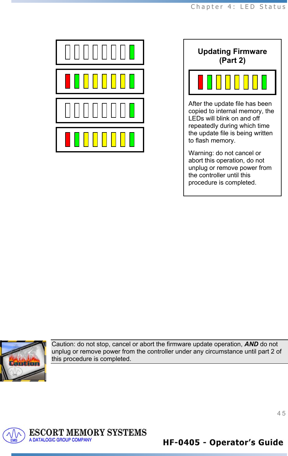
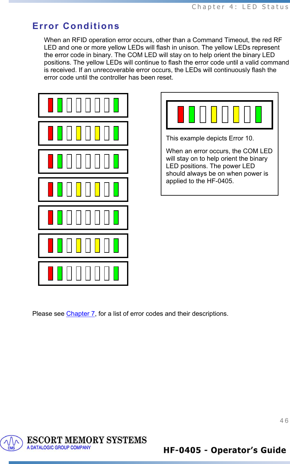
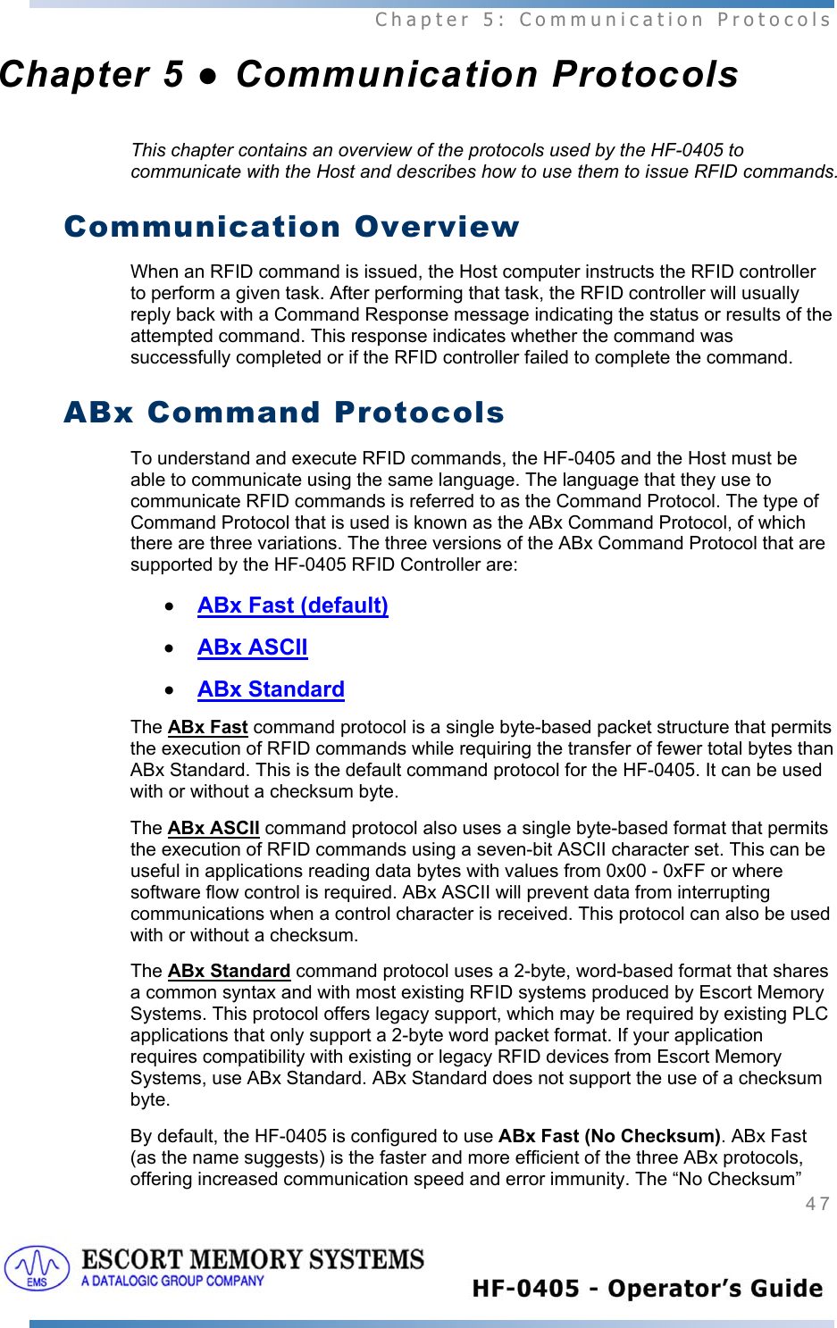
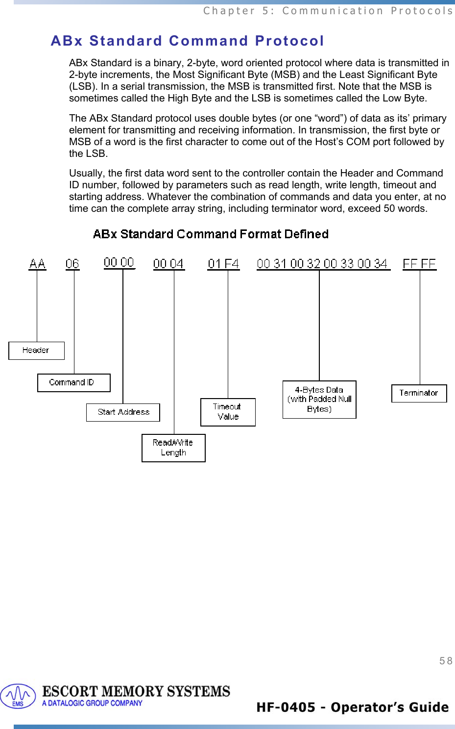
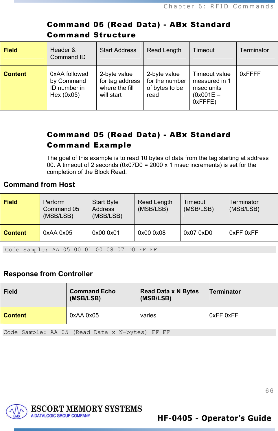
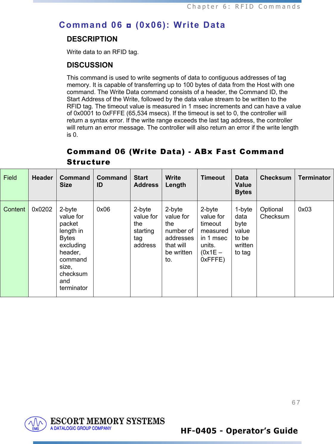
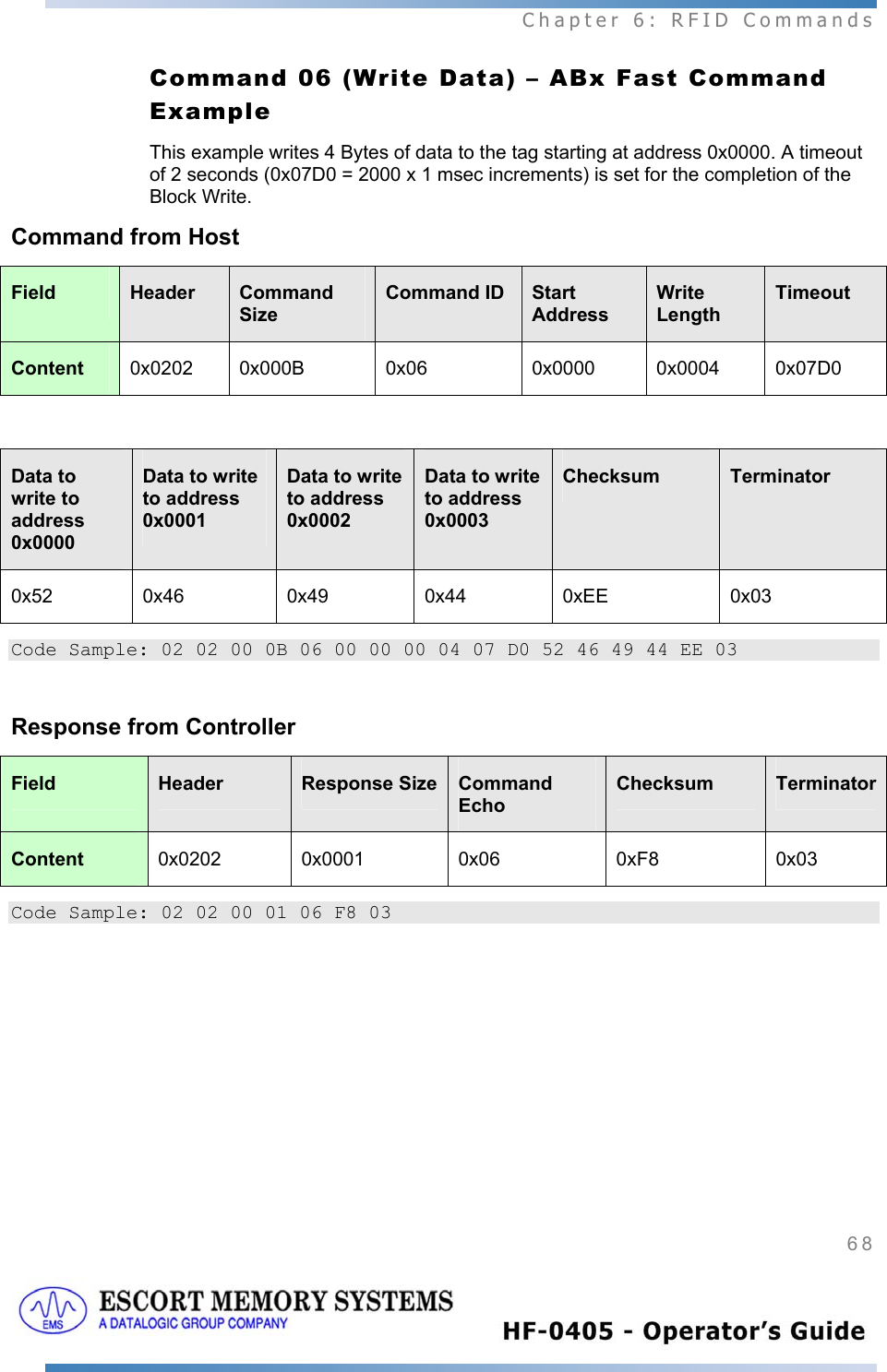
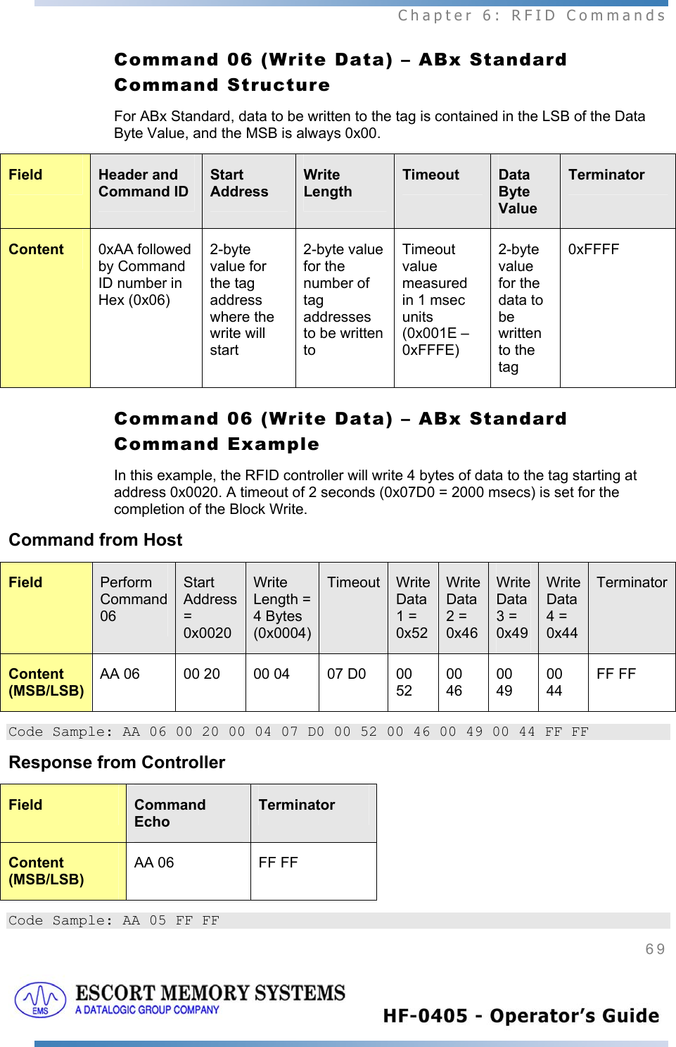
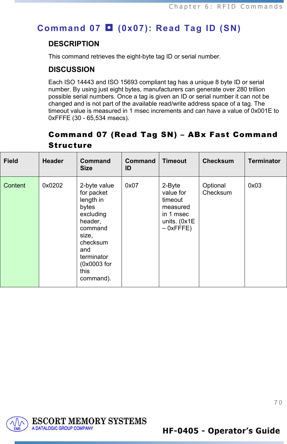
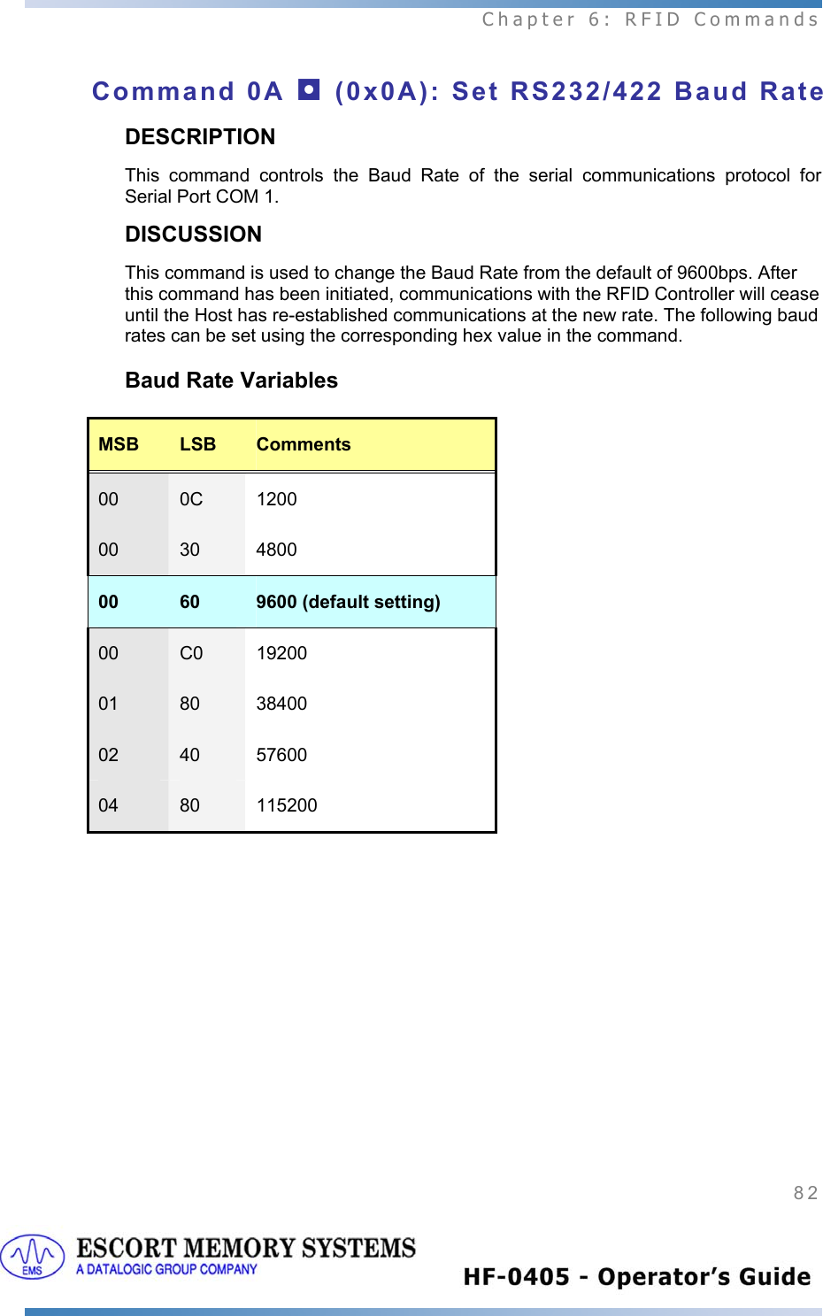
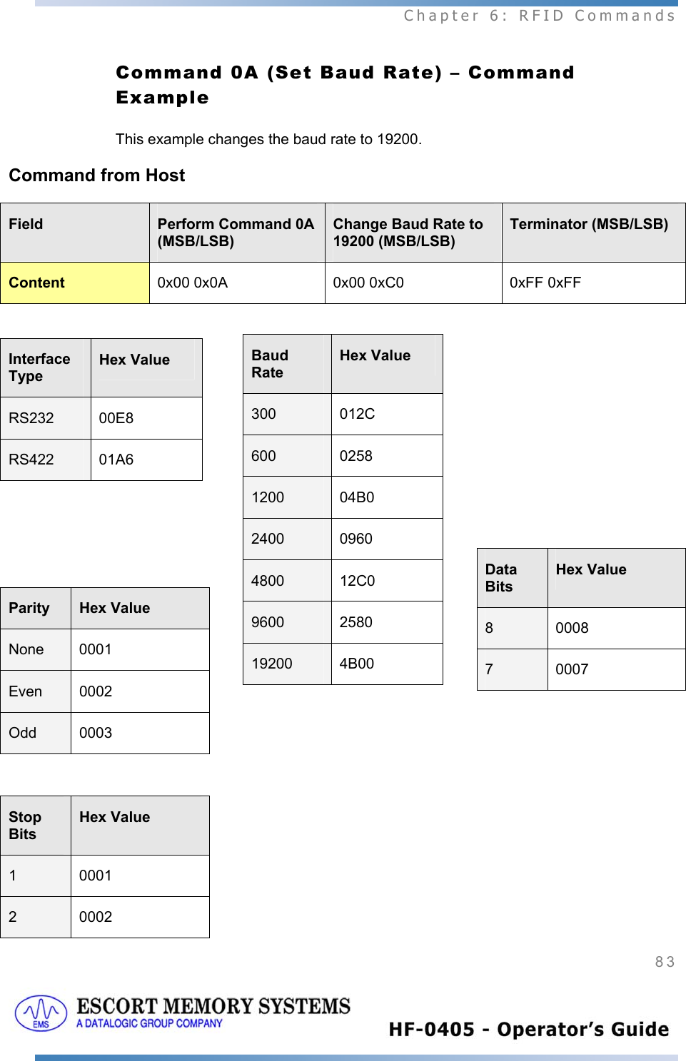
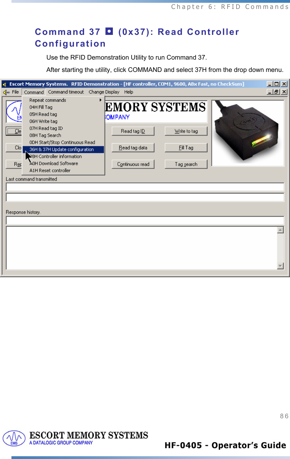
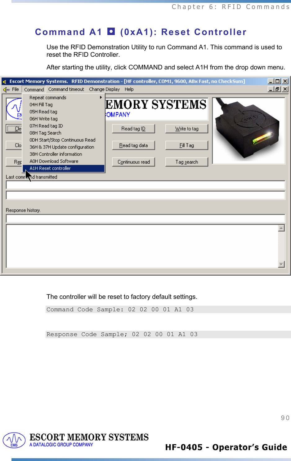
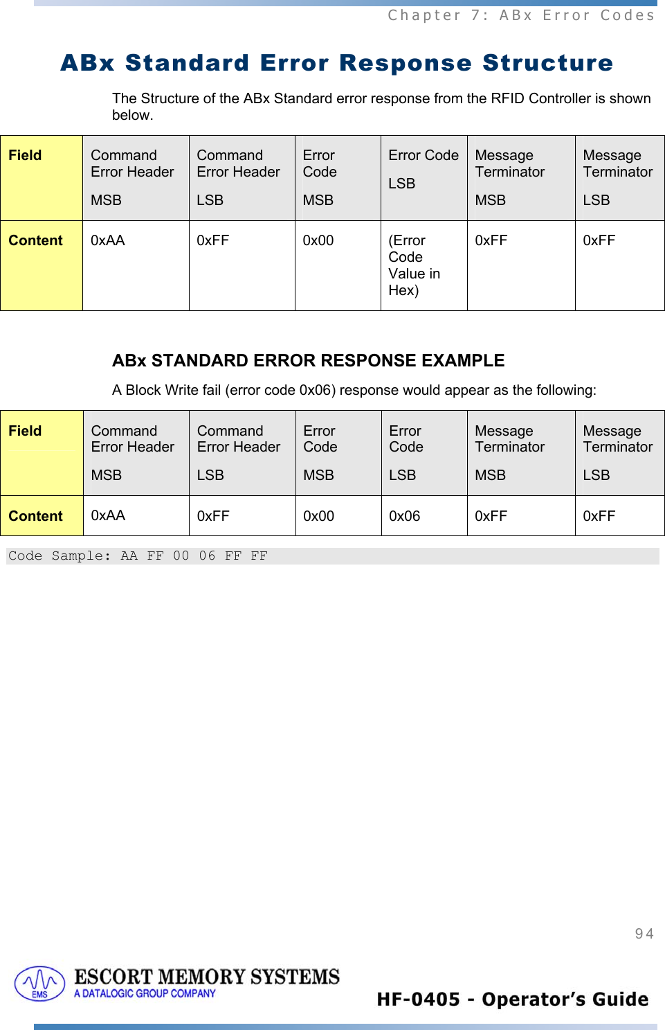
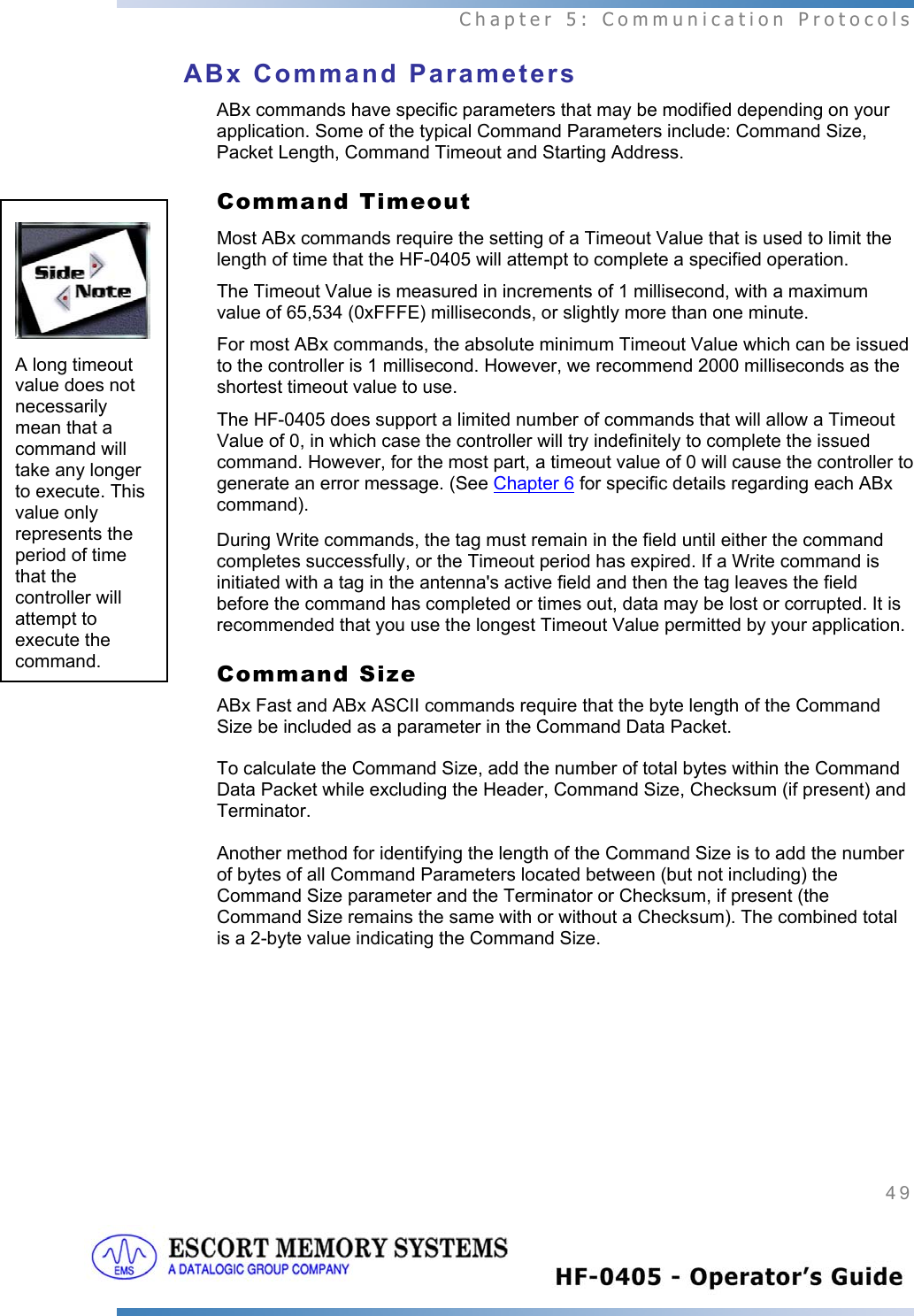
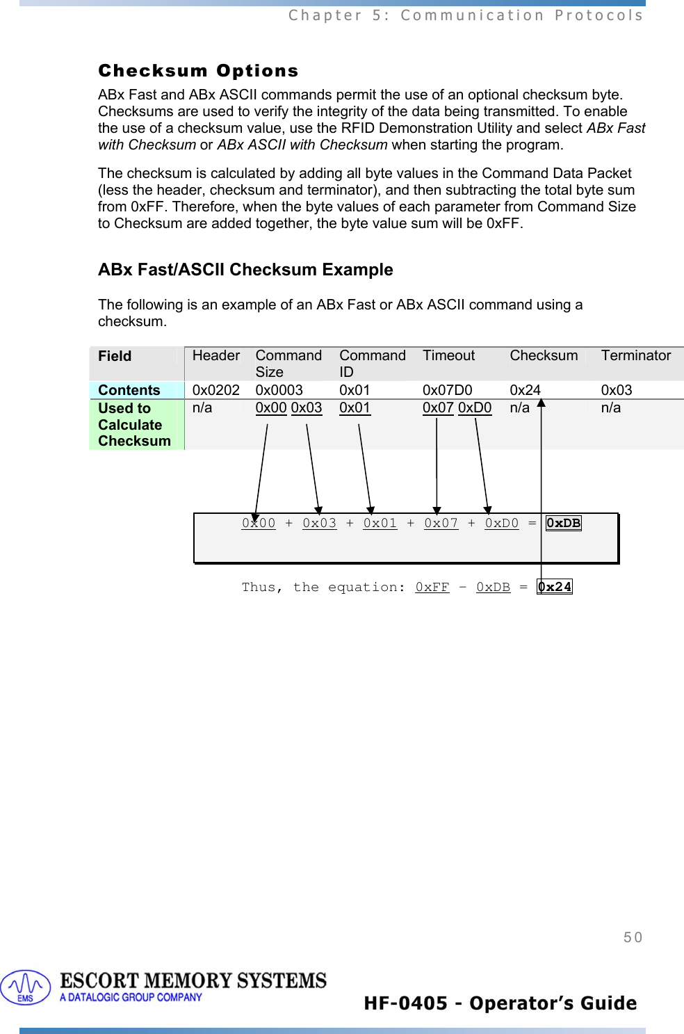
![Chapter 5: Communication Protocols 48 option is chosen for its ease of use. However, we encourage the use of checksums for most applications. ABx Command Structures In its simplest form, ABx commands are comprised of a header, a number of parameters, and a command terminator. The structure of every ABx command will, at the very least, contain these basic elements. [Command Header - Command Parameters - Command Terminator] In ABx Fast and ABx ASCII, each command begins with the 2-byte header 0x0202 and ends with the one-byte terminator 0x03. In ABx Standard, every command begins with the one-byte header "0xAA," and ends with the two-byte terminator "0xFFFF". See the table below for further clarification. ABx Protocols Headers and Terminators ABx Protocol Header Terminator ABx Fast 0x0202 0x03 ABx ASCII 0x0202 <STX><STX> 0x03 <ETX> ABx Standard 0xAA 0xFFFF When a command is issued from the Host, the RFID controller stores the incoming data packet in a buffer while it scans the data for a start character (0x0202 or 0xAA). When a start character is found, it checks for the proper terminator (0x03, <ETX> or 0xFFFF). Having identified a potentially valid command string, the controller will verify the format of the data and either perform the requested function or generate an error message. ABx Response Structures After receiving and/or performing a command, the HF-0405 will issue a Command Response message back to the Host. Similar in structure to ABx commands, an ABx Command Response contains a header, a number of response values, and a response terminator. The response structure for all three ABx protocols consists of these same basic elements: [Response Header - Response Values - Response Terminator] For all three ABx protocols, the response header and response terminator will be the same as their command header and command terminator counterparts.](https://usermanual.wiki/Balluff/HF-0405-XXX-01.Users-Manual-Part-II/User-Guide-514281-Page-17.png)
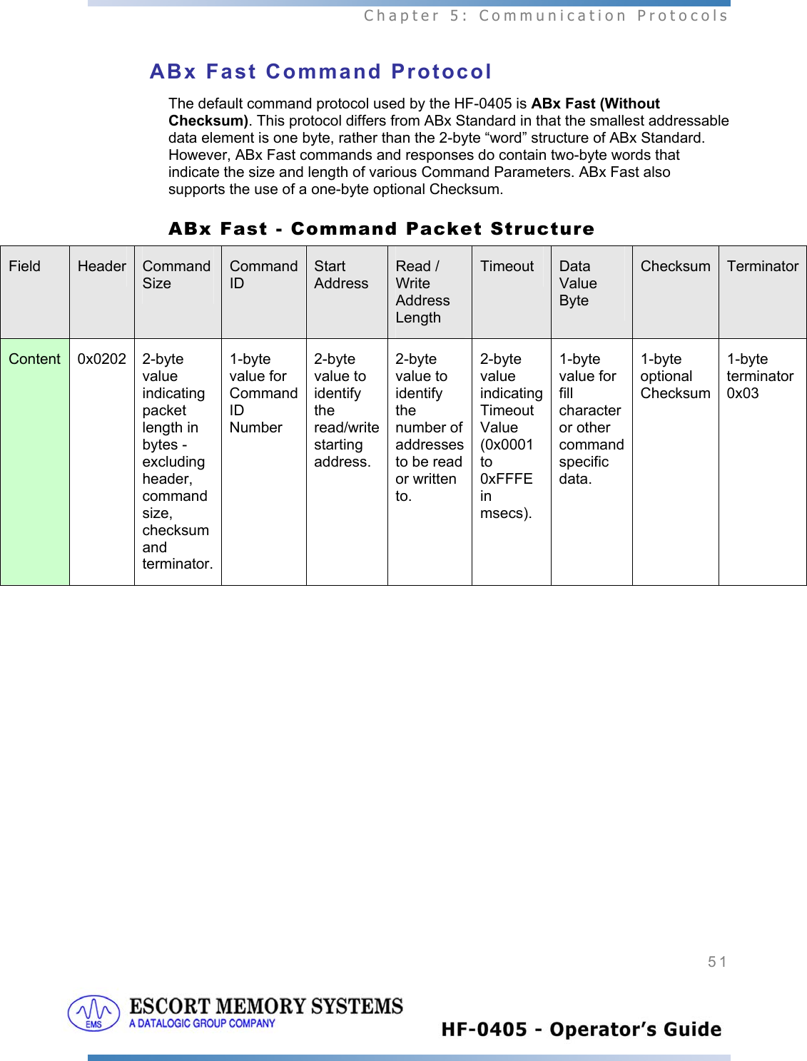
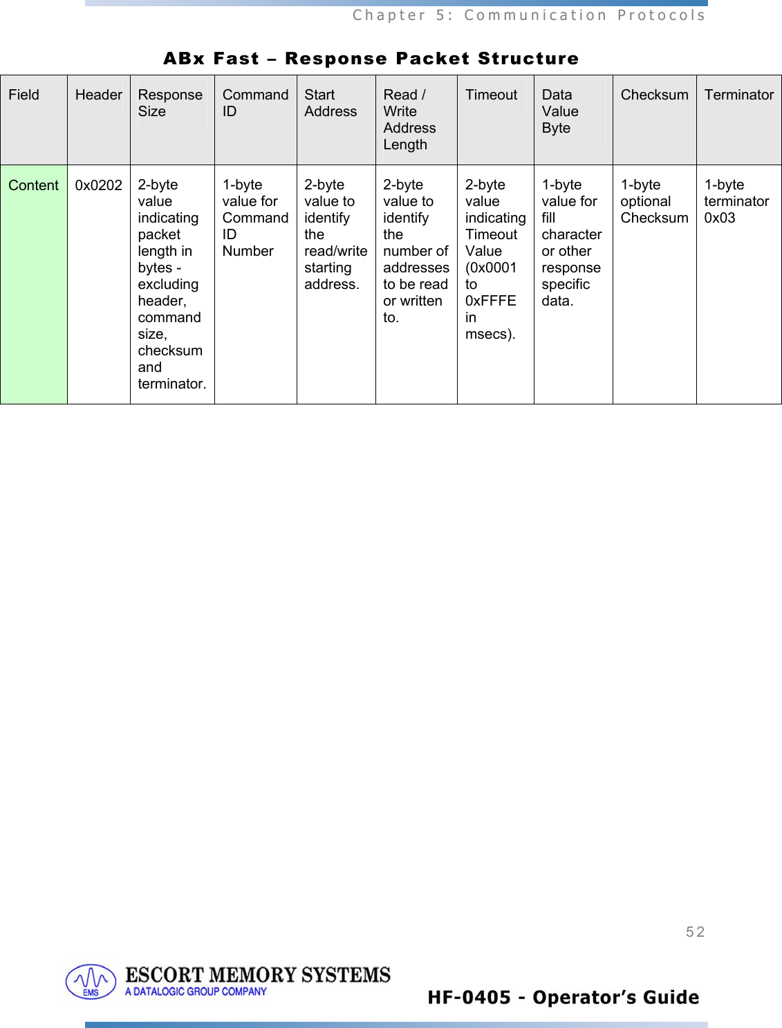
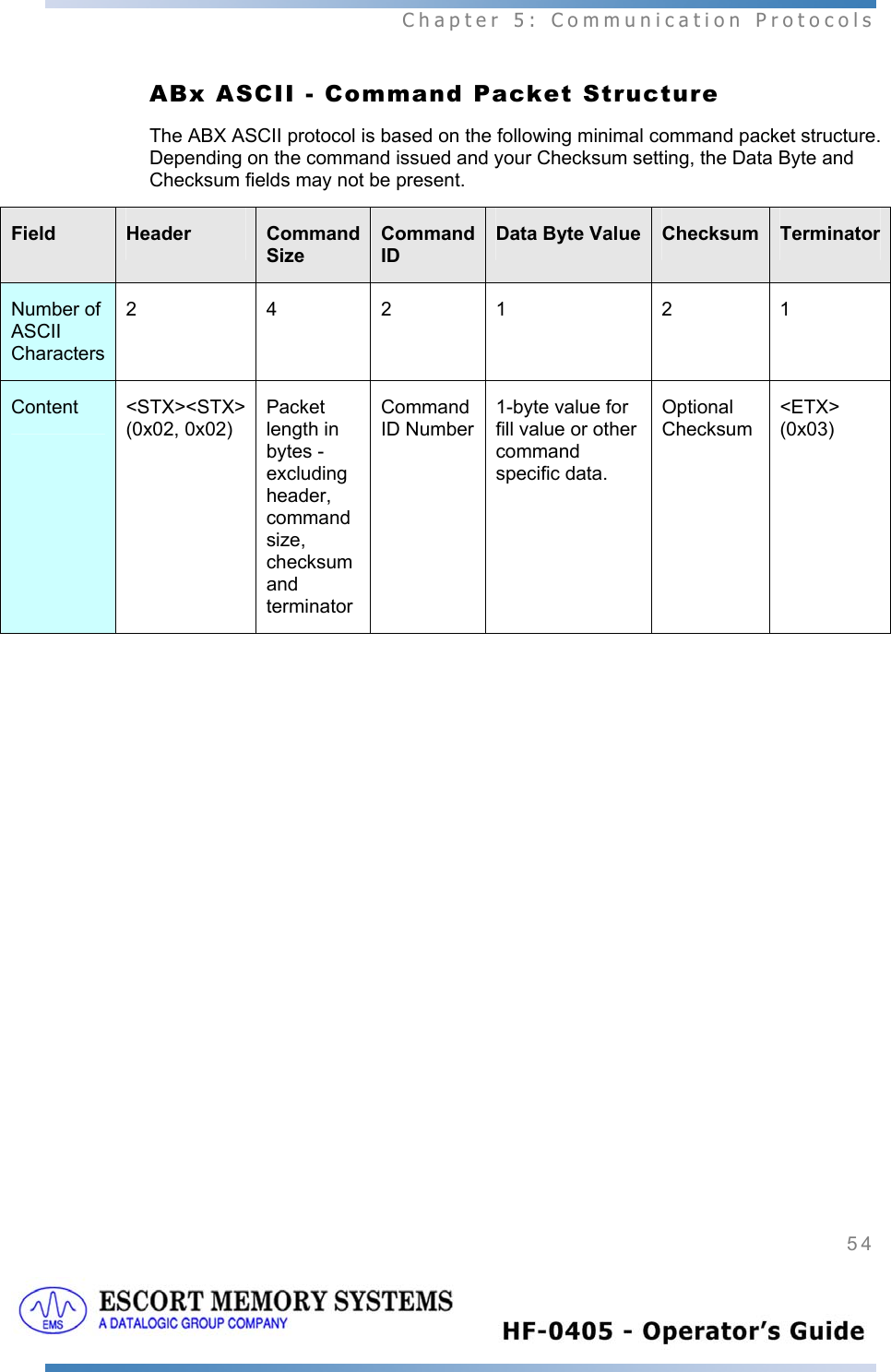
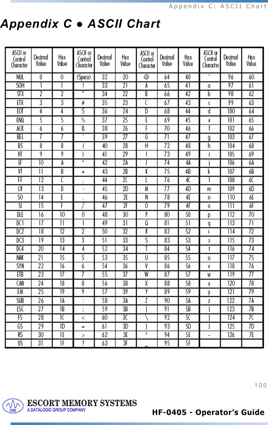
![Chapter 5: Communication Protocols 53 ABx ASCII Command Protocol The ABx ASCII command protocol is based on the ABx Fast command protocol, however, ABx ASCII goes one step further by converting command hex values into printable ASCII characters. In another words, hex values displayed in an ABx Fast command are transmitted as separate ASCII characters in ABx ASCII. ABx ASCII uses the ASCII equivalent of ABx Fast’s 2-byte header and 1-Byte terminator (that are always [STX (0x02) STX (0x02)] and [ETX (0x03)] respectively). The values of all other fields are displayed as ASCII hex notation. The permitted values are the numbers 0-9 and the capital letters A-F. The characters 0-9 and A-F equal the Hex values 0x30 thru 0x39, and 0x41 thru 0x46. ABx ASCII also supports the use of Xon/Xoff handshaking; ABx Fast and ABx Standard do not. See Appendix C, for a list of ASCII characters and their corresponding Hex and Decimal values. ABx ASCII Character Values In ABx ASCII, the hex value 0xAB (decimal 171) is transmitted as the 2-character string AB. For example, the 2 bytes “0x41” and “0x42” are equivalent to the ASCII characters 'A' and 'B'. If you refer back to the ABx Fast section earlier n this chapter, you will notice that you can structure ABx ASCII commands by using ASCII characters to represent each digit of a hex value, excluding header and terminator which are already ASCII characters (<STX> and <ETX>). ABx ASCII Command and Response Size The ABx ASCII command protocol requires that a 2-byte value indicating the length of the Command Size be included in the command packet. The Command Size is calculated by adding the byte values of all parameters and data values located between the Command Size parameter and Checksum (if used) or Terminator. The Command Size includes the Command ID value and parameters such as address definitions for tag Read/Writes. The Command Size remains the same with, or without a checksum. In ABx ASCII, the Command Size and Response Size is the combined number of Hex bytes, not the number of ASCII characters used to represent the hex values. STX = Send Transmission, ETX = End Transmission](https://usermanual.wiki/Balluff/HF-0405-XXX-01.Users-Manual-Part-II/User-Guide-514281-Page-22.png)