Balluff UHF-CNTL-02 UHF RFID Controller User Manual Version 28 05 09
BALLUFF inc UHF RFID Controller Version 28 05 09
Balluff >
User Manual
COBALT UHF-SERIES
PAGE 2 OF 140
Datalogic Automation reserves the right to make modifications and improvements to
its products and/or documentation without prior notification. Datalogic Automation
shall not be liable for technical or editorial errors or omissions contained herein, nor
for incidental or consequential damages resulting from the use of this material.
The text and graphic content of this publication may be used, printed and distributed
only when all of the following conditions are met:
Permission is first obtained from Datalogic Automation.
The content is used for non-commercial purposes only.
Copyright information is clearly displayed (Copyright © 2009, Datalogic Automation
S.r.l., All Rights Reserved).
The content is not modified.
The following are trademarks and/or registered trademarks of Datalogic Automation:
Escort Memory Systems®, and the Escort Memory Systems logo, Cobalt UHF™,
RFID AT WORK™, C-Macro™, C-MacroBuilder™, ABx™ and Cobalt Dashboard™.
COPYRIGHT © 2009 DATALOGIC AUTOMATION S.R.L., ALL RIGHTS RESERVED
28/05/2009
Cobalt UHF Series Operator’s Manual
For Models: UHF-CNTL-232/485/IND –02 EU
UHF-CNTL-232/485/IND –02 US
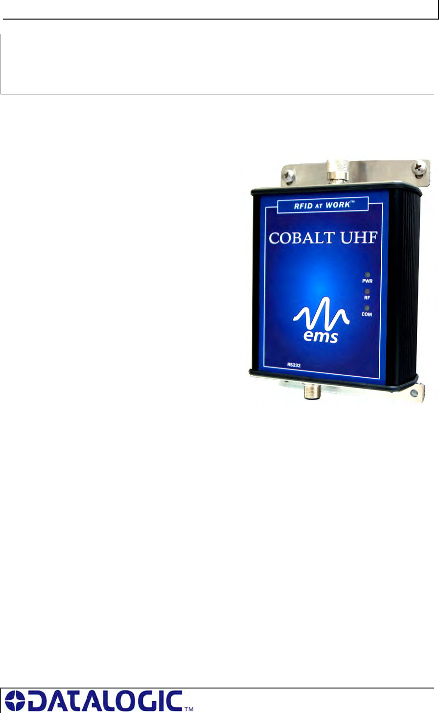
COBALT UHF-SERIES
PAGE 3 OF 140
For Cobalt UHF-Series
RFID Controller Models:
UHF-CNTL-232-02
UHF-CNTL-485-02
UHF-CNTL-IND-02
COBALT UHF-SERIES
RFID CONTROLLERS
Ultra High Frequency, Multi Protocol, Passive Radio Frequency Identification Controllers
OPERATOR’S MANUAL
How to Install, Configure and
Operate the Cobalt UHF-Series
RFID Controllers
COBALT UHF-SERIES REGULATORY COMPLIANCE
PAGE 4 OF 140
REGULATORY COMPLIANCE
FCC Compliance
Modifications or changes to this equipment without the expressed written approval of
Datalogic could void the authority to use the equipment.
This device complies with PART 15 of the FCC Rules. Operation is subject to the
following two conditions: (1) This device may not cause harmful interference, and (2)
this device must accept any interference received, including interference which may
cause undesired operation.
FCC ID: E36-UHF-CNTL-02
Radio Compliance
ENGLISH
Contact the competent authority responsible for the management of radio frequency
devices of your country to verify any possible restrictions or licenses required. Refer
to the web site:
http://europa.eu.int/comm/enterprise/rtte/spectr.htm for further information.
ITALIANO
Prendi contatto con l'autorità competente per la gestione degli apparati a radio
frequenza del tuo paese, per verificare eventuali restrizioni o licenze. Ulteriori
informazioni sono disponibili sul sito:
http://europa.eu.int/comm/enterprise/rtte/spectr.htm.
FRANÇAIS
Contactez l'autorité compétente en la gestion des appareils à radio fréquence de
votre pays pour vérifier d'éventuelles restrictions ou licences. Pour tout
renseignement vous pouvez vous adresser au site web:
http://europa.eu.int/comm/enterprise/rtte/spectr.htm.
DEUTSCH
Wenden Sie sich an die für Radiofrequenzgeräte zuständige Behörde Ihres Landes,
um zu prüfen ob es Einschränkungen gibt, oder eine Lizenz erforderlich ist. Weitere
Informationen finden Sie auf der Web Seite:
http://europa.eu.int/comm/enterprise/rtte/spectr.htm.
COBALT UHF-SERIES REGULATORY COMPLIANCE
PAGE 5 OF 140
ESPAÑOL
Contacta la autoridad competente para la gestión de los dispositivos de radio
frecuencia de tu país, para verificar cualesquiera restricciones o licencias posibles
requerida. Además se puede encontrar mas información en el sitio Web:
http://europa.eu.int/comm/enterprise/rtte/spectr.htm.
Power Supply
This product is intended to be installed by Qualified Personnel only.
This device is intended to be supplied by a UL Listed or CSA Certified Power Unit
with «Class 2» or LPS power source.
COBALT UHF-SERIES CONTENTS
PAGE 6 OF 140
CONTENTS
LIST OF TABLES ................................................................................................10
LIST OF FIGURES...............................................................................................11
CHAPTER 1: GETTING STARTED............................................... 12
1.1 INTRODUCTION ..................................................................................12
1.1.1 About this Manual...........................................................................................12
1.2 COBALT CONTROLLER OVERVIEW .......................................................13
1.2.1 Cobalt Controller Features ..............................................................................13
1.2.2 UHF Operating Frequencies Options ...............................................................13
1.2.3 Connection and Communication Interface Options ...........................................14
1.2.4 Cobalt Controllers - Interface Connectors ........................................................14
1.2.5 Package Contents ..........................................................................................14
1.3 COBALT CONTROLLER DIMENSIONS ....................................................15
1.3.1 UHF-CNTL-232/485/IND-02 Controller Dimensions ..........................................15
1.4 COBALT UHF RFID ANTENNAS...........................................................17
1.4.1 Cobalt UHF RFID Antennas - Features ............................................................17
1.4.2 Cobalt UHF RFID Antennas - Models and Sizes ...............................................17
1.4.3 UHF-ANT-2626-01-86 Antenna Dimensions .....................................................18
1.4.4 UHF-ANT-3030-01-91 Antenna Dimensions .....................................................19
1.4.5 Connecting the Antenna to the Controller ........................................................20
1.4.6 Optional Mounting Kit for Antenna Installation..................................................22
1.5 SUBNET16™ MULTIDROP PROTOCOL ..................................................23
CHAPTER 2: INSTALLING THE COBALT UHF ............................. 24
2.1 PREPARING FOR INSTALLATION...........................................................24
2.1.1 Power Requirements ......................................................................................24
2.1.2 Installation Guidelines ....................................................................................24
2.2 INSTALLING THE UHF-CNTL-232-02...................................................25
2.2.1 Steps to Install the UHF-CNTL-232-02.............................................................26
2.2.2 UHF-CNTL-232-02 Cabling Information ...........................................................27
2.3 INSTALLING THE UHF-CNTL-485-02...................................................29
2.3.1 Steps to Install the UHF-CNTL-485-02.............................................................30
2.3.2 UHF-CNTL-485-02 Cabling Information ...........................................................31
2.4 INSTALLING THE UHF-CNTL-IND-02 ..................................................32
2.4.1 Steps to Install the UHF-CNTL-IND-02 ............................................................33
2.4.2 UHF-CNTL-IND-02 Cabling Information ...........................................................34
CHAPTER 3: CONFIGURING THE COBALT UHF.......................... 36
3.1 CONFIGURING THE COBALT VIA DASHBOARD UTILITY ...........................36
3.2 NOTE ABOUT THE READER POWER......................................................38

COBALT UHF-SERIES CONTENTS
PAGE 7 OF 140
3.3 CONFIGURING THE COBALT VIA “CONFIGURATION TAG” .......................38
3.3.1 Restoring Factory Defaults..............................................................................38
3.3.2 Manually Assigning Node ID (Cobalt -485 Model Only) .....................................39
3.3.3 Automatic Node ID Assignment via Gateway (Cobalt -485 Model Only) ............40
3.3.4 Automatic Node ID Assignment via Hub (Cobalt -485 Model Only) ....................41
CHAPTER 4: LED STATUS......................................................... 42
4.1 LED FUNCTIONS OVERVIEW ...............................................................42
4.1.1 LED Behavior for Cobalt UHF-CNTL-232-02 ....................................................42
4.1.2 LED Behavior for Cobalt UHF-CNTL-485-02 ....................................................43
4.1.3 LED Behavior for Cobalt UHF-CNTL-IND-02 ....................................................44
CHAPTER 5: COMMAND PROTOCOLS........................................ 45
5.1 COMMAND PROTOCOLS OVERVIEW......................................................45
5.2 RFID COMMAND TABLE......................................................................46
5.2.1 RFID Commands - Note About the UHF-G2-525xx Tag Memory Structure .........48
5.3 ABX COMMAND PROTOCOL OVERVIEW ................................................49
5.3.1 ABx Command Packet Structure......................................................................49
5.3.2 ABx Protocols - Headers and Terminators .......................................................49
5.3.3 ABx Response Packet Structure......................................................................50
5.4 ABX FAST COMMAND PROTOCOL........................................................51
5.4.1 ABx Fast - Command / Response Procedure....................................................51
5.4.2 ABx Fast - Command Packet Structure ............................................................52
5.4.3 ABx Fast – Command Packet Elements ...........................................................53
5.4.4 ABx Fast - Multi-Tag Command Packet Structure .............................................56
5.4.5 ABx Fast - Multi-Tag Command Packet Elements.............................................57
5.4.6 ABx Fast - Response Packet Structure ............................................................58
5.4.7 ABx Fast Protocol: Error Response Packet Structure ......................................59
Single-Tag RFID Command 0xC2: Re ad EP C Co de ....................................................60
Single-Tag RFID Command 0xC3: Wr it e E PC C o de ....................................................61
Multi-Tag RFID Command 0xC4: Re ad E P C Co d e ......................................................62
Controller Specific Command 0xC0: Set UHF Configuration.............................................64
Controller Specific Command 0xC1: Get UHF Configuration ............................................66
5.5 CBX COMMAND PROTOCOL ................................................................67
5.5.1 CBx - Command Procedure.............................................................................67
5.5.2 CBx - Command Packet Structure ...................................................................68
5.5.3 CBx Response Packet Structure......................................................................69
5.5.4 CBx Multi-Tag Command Packet Structure ......................................................71
5.5.5 CBx Multi-Tag Command Packet Elements ......................................................72
5.5.6 CBx Multi-Tag Response Packet Structures .....................................................73
5.5.7 CBx Multi-Tag Response Final Termination Packet Structure............................74
5.5.8 CBx Protocol: Error Response Packet Structure...............................................75
CBx Single-Tag RFID Command 0xC2: Rea d EP C Cod e .............................................76
CBx Single-Tag RFID Command 0xC3: Wr i te E PC C od e .............................................78
Multi-Tag RFID Command 0xC4: Re ad E P C Co d e ......................................................80
Controller Specific Command 0xC0: Set UHF Configuration.............................................82
Controller Specific Command 0xC1: Get UHF Configuration ............................................85
5.6 ERROR CODE TABLE ..........................................................................87

COBALT UHF-SERIES CONTENTS
PAGE 8 OF 140
CHAPTER 6: ETHERNET/IP INTERFACE..................................... 89
6.1 ETHERNET/IP CONFIGURATION OVERVIEW ...........................................89
6.2 HTML SERVER & ONDEMAND PLC SUPPORT ......................................90
6.3 HTML SERVER AND ONDEMAND UTILITIES ..........................................90
6.4 IP CONFIGURATION VIA HTML SERVER ...............................................91
6.5 ONDEMAND CONFIGURATION FOR ETHERNET/IP...................................93
6.6 CONFIGURING PLC CONTROLLER TAGS ..............................................96
6.7 CHECKING ONDEMAND STATUS ..........................................................97
6.8 VERIFYING DATA EXCHANGE WITH RSLOGIX 5000 ..............................98
6.8.1 Ethernet/IP Handshaking ................................................................................98
6.8.2 Ethernet/IP Handshaking Example ..................................................................99
6.9 ETHERNET/IP: OBJECT MODEL .........................................................100
6.9.1 Ethernet/IP Required Objects........................................................................ 101
6.9.2 EtherNet/IP: Vendor Specific Objects ............................................................107
6.9.3 Application Object (0x67 – 10 Instances) ........................................................110
CHAPTER 7: MODBUS TCP INTERFACE................................... 112
7.1 MODBUS TCP OVERVIEW .................................................................112
7.2 MODBUS TCP CONFIGURATION VIA HTML SERVER ............................112
7.2.1 Setting the IP Address of the Cobalt.............................................................. 112
7.2.2 Modbus TCP - Command Packet Structure ....................................................115
7.2.3 Modbus TCP - Response Packet Structure .................................................... 116
7.2.4 Modbus TCP - Mapping for Node 33 ..............................................................116
7.3 MODBUS TCP - HANDSHAKING .........................................................118
7.3.1 Modbus TCP - Host/Cobalt Handshaking .......................................................119
7.3.2 Modbus TCP - Handshaking Example ............................................................119
CHAPTER 8: STANDARD TCP/IP INTERFACE ........................... 121
8.1 STANDARD TCP/IP OVERVIEW..........................................................121
8.2 STANDARD TCP/IP - IP CONFIGURATION VIA HTML SERVER ..............121
8.2.1 Setting the IP Address of the Cobalt.............................................................. 122
8.3 STANDARD TCP/IP - COMMAND & RESPONSE EXAMPLES ...................124
8.3.1 Standard TCP/IP - Command Structure & Example ........................................ 125
8.3.2 Standard TCP/IP - Response Structure & Example......................................... 126
CHAPTER 9: RFID OVERVIEW ................................................. 127
9.1 RFID OVERVIEW..............................................................................127
9.2 OVERVIEW ON ULTRA HIGH FREQUENCY RFID APPLICATIONS.............128
9.2.1 UHF Standards and Regulations ................................................................... 128
9.2.2 UHF Signal Propagation ............................................................................... 130
9.2.3 Limiting Interference and UHF Signal Attenuation .......................................... 132
APPENDIX A: TECHNICAL SPECIFICATIONS............................. 133
COBALT UHF CONTROLLERS - TECHNICAL SPECIFICATIONS...............................133

COBALT UHF-SERIES CONTENTS
PAGE 9 OF 140
COBALT UHF ANTENNAS - TECHNICAL SPECIFICATIONS.....................................135
APPENDIX B: MODELS & ACCESSORIES .................................. 136
COBALT UHF SERIES ACCESSORIES.................................................................136
COBALT UHF-SERIES RFID CONTROLLERS.......................................................136
COBALT UHF-SERIES ANTENNAS .....................................................................137
SUBNET16 GATEWAYS.....................................................................................137
SUBNET16 HUBS.............................................................................................137
POWER SUPPLIES............................................................................................137
SOFTWARE APPLICATIONS ...............................................................................138
COBALT CABLES & ACCESSORIES ....................................................................138
WARRANTY .............................................................................. 140

COBALT UHF-SERIES LIST OF TABLES
PAGE 10 OF 140
LIST OF TABLES
Table 1-1: Connection and Communication Interface Options __________________________ 14
Table 1-2: Cobalt Controllers - Interface Connectors _________________________________ 14
Table 1-3: Package Contents ___________________________________________________ 14
Table 1-4: Cobalt UHF RFID Antennas - Models and Sizes ____________________________ 17
Table 1-5: Controller-Antenna Cabling Information ___________________________________ 21
TTable 2-1: COM Port Parameter Defaults (UHF-CNTL-232-02) ________________________ 26
Table 2-2: RS232 Connector - Pinout _____________________________________________ 27
Table 2-3: RS485 Connector – Pinout ____________________________________________ 31
Table 2-4: Ethernet Connector - Pinout____________________________________________ 34
Table 2-5: Power Connector - Pinout _____________________________________________ 35
Table 3-1:Reader Radiated Power Limits __________________________________________ 38
Table 3-2: Configuration Tag – Restored Factory Defaults _____________________________ 39
Table 4-1: UHF-CNTL-232-02 - LEDs Description ___________________________________ 42
Table 4-2: UHF-CNTL-485-02 - LEDs Description ___________________________________ 43
Table 4-3: UHF-CNTL-IND-02 - LEDs Description ___________________________________ 44
Table 5-1: Command Protocol Matrix _____________________________________________ 45
Table 5-2: RFID Command Table ________________________________________________ 47
Table 5-3: UHF-G2-525xxx Tag Memory Structure___________________________________ 48
Table 5-4: ABx Protocols - Headers and Terminators_________________________________ 49
Table 5-5: ABx Fast - Command Packet Structure ___________________________________ 51
Table 5-6: ABx Fast - Command Packet Structure ___________________________________ 52
Table 5-7: ABx Fast - Command Size Parameter ____________________________________ 53
Table 5-8: ABx Fast - Checksum Example _________________________________________ 55
Table 5-9: ABx Fast - Anti-Collision Command Packet Structure ________________________ 56
Table 5-10: ABx Fast - Response Packet Structure __________________________________ 58
Table 5-11: ABx Fast - Error Response Structure____________________________________ 59
Table 5-12: CBx Command Packet Structure _______________________________________ 68
Table 5-13: CBx Command Packet Structure _______________________________________ 69
Table 5-14: CBx Response Packet Structure _______________________________________ 70
Table 5-15: CBx Multi-Tag Command Packet Structure _______________________________ 72
Table 5-16: CBx Multi-Tag Response Packet Structure _______________________________ 73
Table 5-17: CBx Multi-Tag Response Final Termination Packet Structure _________________ 74
Table 5-18: CBx - Error Response Packet Structure__________________________________ 75
Table 5-19: Error Code Table___________________________________________________ 88
Table 6-1: Data Type Definitions________________________________________________ 101
Table 7-1: Modbus TCP - Command Packet Structure _______________________________ 115
Table 7-2: Modbus TCP - Response Packet Structure _______________________________ 116
Table 7-3: Modbus TCP - Mapping for Node 33 ____________________________________ 117
Table 8-1: Standard TCP/IP - Command Structure & Example ________________________ 125
Table 8-2: Standard TCP/IP - Response Structure & Example_________________________ 126
Table 9-1:Reader Radiated Power Limits Expressed in Watt or dBm ___________________ 129
Table Appendix B-1:Cobalt UHF Series Accessories ________________________________ 136
Table Appendix B-2: Cobalt Cables and Accessories ________________________________ 139
COBALT UHF-SERIES LIST OF FIGURES
PAGE 11 OF 140
LIST OF FIGURES
Figure 1-1: Cobalt UHF Controller Dimensions – Top View ____________________________ 15
Figure 1-2: Cobalt UHF Controller Dimensions – Front View ___________________________ 16
Figure 1-3: Cobalt UHF Controller Dimensions – Right View ___________________________ 16
Figure 1-4: UHF-ANT-2626-01-86 Antenna Dimensions_______________________________ 18
Figure 1-5: UHF-ANT-3030-01-91 Antenna Dimensions_______________________________ 19
Figure 1-6: Connecting the Antenna to the Controller _________________________________ 20
Figure 1-7: TNC-Reverse Female Connector for Antenna Feeding ______________________ 21
Figure 1-8: UHF-CBL-0X - Controller-Antenna Coaxial Cable __________________________ 21
Figure 1-9:Optional Mounting Kit for Antennas ______________________________________ 22
Figure 1-10: Subnet16™ Industrial Gateway and Industrial Hub ________________________ 23
Figure 2-1: UHF-CNTL-232-02 Communication Interfaces _____________________________ 25
Figure 2-2: UHF-CNTL-232-02 Controller - RS232 Connector __________________________ 27
Figure 2-3: RS232 Serial Interface Cable – Schematic________________________________ 28
Figure 2-4: CBL-1493 Mountable Connector________________________________________ 28
Figure 2-5: UHF-CNTL-485-02 Communication Interfaces _____________________________ 29
Figure 2-6: UHF-CNTL-485-02 Controller - RS485 Connector __________________________ 31
Figure 2-7: UHF-CNTL-IND-02 Communication Interfaces_____________________________ 32
Figure 2-8: UHF-CNTL-IND-02 Controller - Ethernet & Power Connectors ________________ 34
Figure 6-1: The HTML Server - Main Page _________________________________________ 91
Figure 6-2: The IP Configuration Page ____________________________________________ 92
Figure 6-3: The OnDemand Configuration Page_____________________________________ 94
Figure 6-4: The OnDemand Status Page __________________________________________ 97
Figure 6-5: RSLogix 5000 ______________________________________________________ 98
Figure 7-1: The HTML Server - Main Page ________________________________________ 113
Figure 7-2: The IP Configuration Page ___________________________________________ 114
Figure 8-1: The HTML Server - Main Page ________________________________________ 122
Figure 8-2: The IP Configuration Page ___________________________________________ 123
Figure 8-3: Standard TCP/IP Protocol Command Packet Structure _____________________ 124
Figure 9-1: Radiowaves Spectrum Diagram _______________________________________ 128
Figure 9-2: Radiofrequency Bands Allocation ______________________________________ 129
Figure 9-3: Circular Polarized Antenna’s Field Pattern _______________________________ 130
Figure 9-4: Circular Polarized Antenna’s Reading Range_____________________________ 131
COBALT UHF-SERIES CHAPTER 1: GETTING STARTED
PAGE 12 OF 140
CHAPTER 1:
GETTING STARTED
1.1 INTRODUCTION
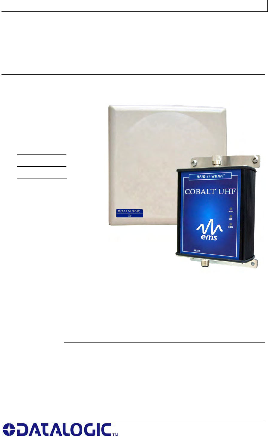
Welcome to the Cobalt UHF-Series RFID Controllers - Operator’s Manual. This
manual will assist you in the
installation, configuration and
operation of the Cobalt UHF RFID
controllers.
The Cobalt UHF-Series is a complete
line of feature-rich, passive, ultra high
frequency, read/write Radio-
Frequency Identification devices that
provide RFID data collection and
control solutions to shop floor, item-
level tracking and material handling
applications. Cobalt UHF controllers
are designed to be compact, rugged
and reliable, in order to meet and
exceed the requirements of the
industrial automation industry.
The Cobalt UHF is ideal for industrial
applications where single or multiple
tags must be read at long distance
and at high speed.
1.1.1 About this Manual
This manual provides guidelines and instructions for installing and operating the
Cobalt UHF-Series RFID Controllers. Included are descriptions of the RFID
command set and examples demonstrating how to issue commands to the Cobalt
RFID Controller.
Numbers expressed in Hexadecimal notation, are prefaced with “0x”. For example,
the number ten in decimal is expressed as 0x0A in hexadecimal. In case of need, the
user should refer to a chart containing Hex values and their corresponding decimal
integers.
COBALT UHF-SERIES CHAPTER 1: GETTING STARTED
PAGE 13 OF 140
1.2 COBALT CONTROLLER OVERVIEW
1.2.1 Cobalt Controller Features
High performance, industrial RFID controller
Features long range, and high speed read/write rates
Supports RS232, RS485 or Ethernet interface connection
RFID Air Protocol: EPCglobalTM Class 1 Generation 2
Compatible with UHF-G2-525 and UHF-G2-525HT RFID tags from Escort Memory
systems; compatible with all Class 1, Gen 2 RFID tags
Supports Escort Memory Systems’ ABx Fast™ and CBx™ RFID command protocols
Operates at the internationally recognized ISM frequencies of 865-870 MHz (ETSI
approved for European use) and of 902-928 MHz (FCC approved for North America
use)
Housed in rugged IP65 rated enclosure
LED status indicators display power status, COM activity and RF activity,
Software programmable, contains flash memory for firmware upgrades and internal
configuration storage
Long range antennas capable of reading EPCglobal Class 1 Gen2.
1.2.2 UHF Operating Frequencies Options
The Cobalt UHF-Series Controllers are available in two different operating frequency
ranges:
865-870 MHz (ETSI approved for European use)
902-928 MHz (FCC approved for North America use)
Please refer to Appendix B - Models & Accessories for the corresponding Cobalt
UHF Controller models.
COBALT UHF-SERIES CHAPTER 1: GETTING STARTED
PAGE 14 OF 140
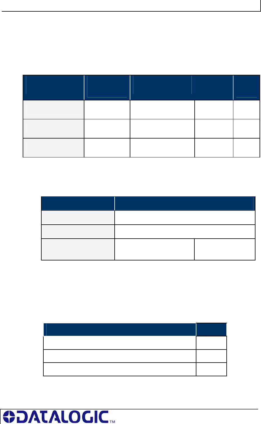
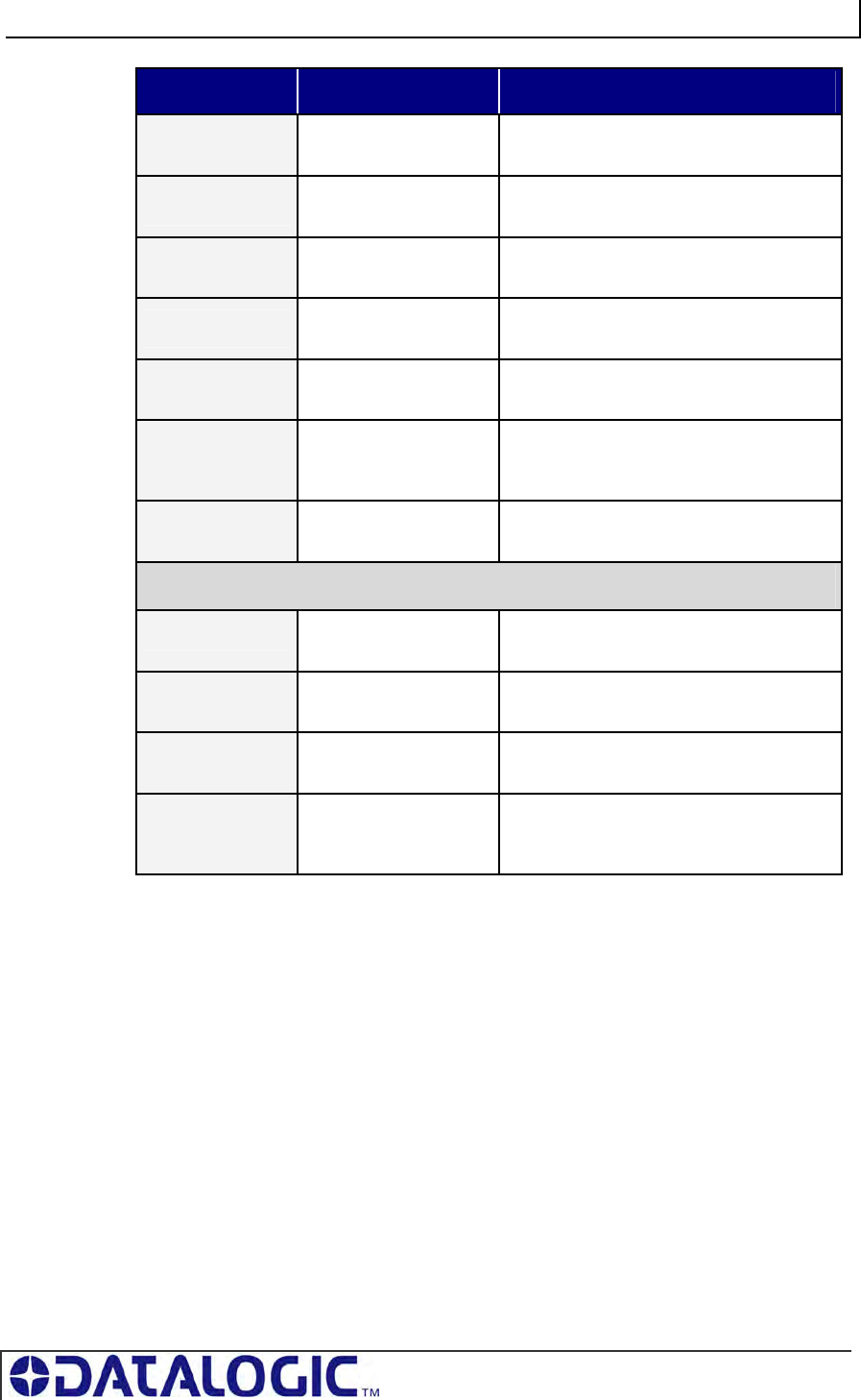
1.2.3 Connection and Communication Interface Options
There are three different models of the Cobalt HF-Series RFID Controllers. Each
model is designed to support a specific communication protocol and interface
connection option. The table below lists the three controller models, their respective
connection types and supported communication interfaces.
CONTROLLER
MODEL INTERFACE
CONNECTION
COMMUNICATION
INTERFACE MAX
CABLE
LENGTH
MAX
SPEED
UHF-CNTL-232-02 RS232 Serial, Point-to-Point,
Host/Controller 15m 115 KB
UHF-CNTL-485-02 RS485 Multidrop (Subnet16)
Bus Architecture 300m 115 KB
UHF-CNTL-IND-02 Ethernet TCP/IP, Ethernet/IP,
Modbus TCP 100m 100
Mb/s
Table 1-1: Connection and Communication Interface Options
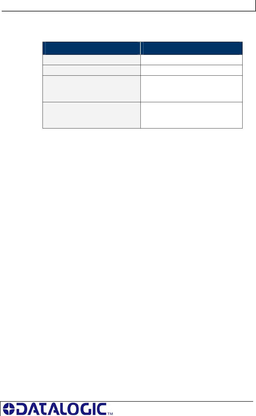
1.2.4 Cobalt Controllers - Interface Connectors
CONTROLLER MODEL INTERFACE CONNECTOR(S)
UHF-CNTL-232-02 8-pin, Male M12 Connector for Power and Data
UHF-CNTL-485-02 5-pin, male M12 Connector for Power and Data
UHF-CNTL-IND-02
(2 connectors)
4-pin, Female M12, D-Code
Connector for Ethernet
5-pin, Male M12
Connector for Power
Table 1-2: Cobalt Controllers - Interface Connectors
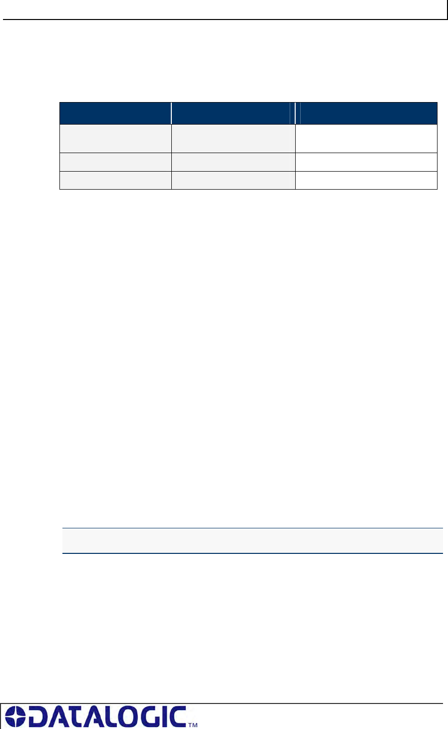
1.2.5 Package Contents
Unpack your Cobalt Controller hardware and accessories. Inspect each piece
carefully, if an item appears to be damaged, notify your EMS’ product distributor.
The Cobalt UHF Series RFID Controller product package contains the following
components:
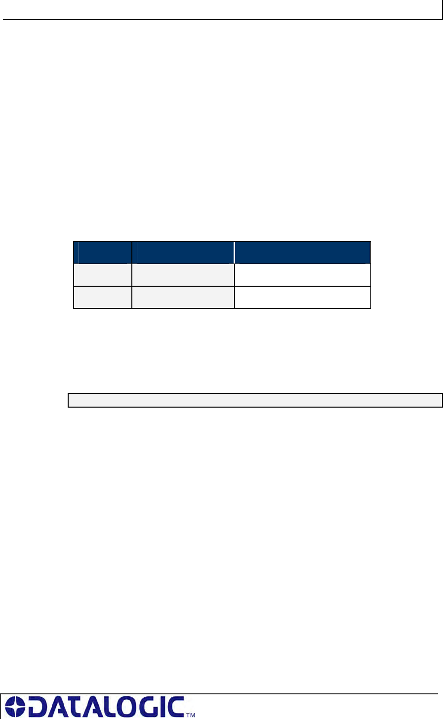
DESCRIPTION QTY
Cobalt UHF-CNTL-xxx-02 RFID Controller 1
UHF-CNTL-xxx-02 Installation Guide 1
Cobalt UHF-Series Configuration Tag 1
Table 1-3: Package Contents
COBALT UHF-SERIES CHAPTER 1: GETTING STARTED
PAGE 15 OF 140
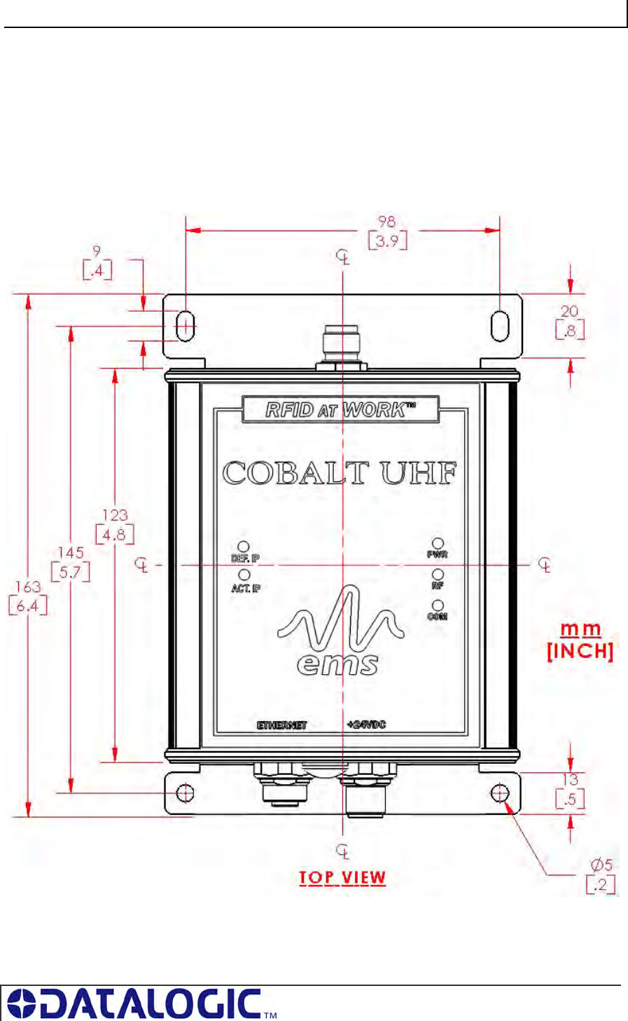
1.3 COBALT CONTROLLER DIMENSIONS
1.3.1 UHF-CNTL-232/485/IND-02 Controller Dimensions
Figure 1-1: Cobalt UHF Controller Dimensions – Top View
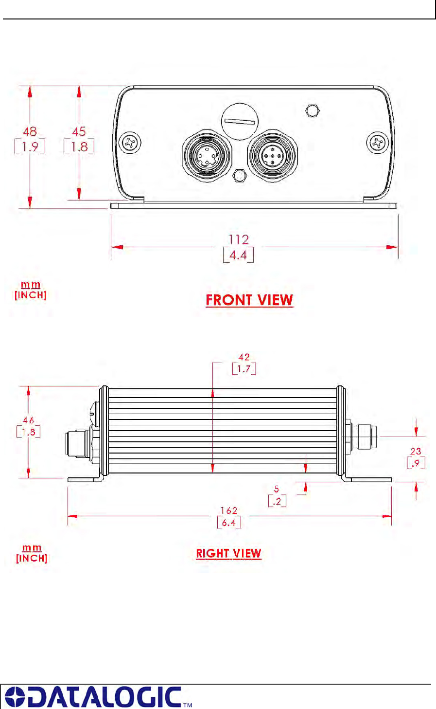
COBALT UHF-SERIES CHAPTER 1: GETTING STARTED
PAGE 16 OF 140
Figure 1-2: Cobalt UHF Controller Dimensions – Front View
Figure 1-3: Cobalt UHF Controller Dimensions – Right View
COBALT UHF-SERIES CHAPTER 1: GETTING STARTED
PAGE 17 OF 140
1.4 COBALT UHF RFID ANTENNAS
1.4.1 Cobalt UHF RFID Antennas - Features
Long read range (up to 3 meters with the UHF-G2-525HT tag and depending on
installation conditions)
Right-hand circular polarization ensures capturing tag data when tag is at random
orientations
3dB Beamwidth, 63° or 65°, providing a large reading zone
Housed in rugged IP67 rated enclosure
Mounting kit for easy installation available
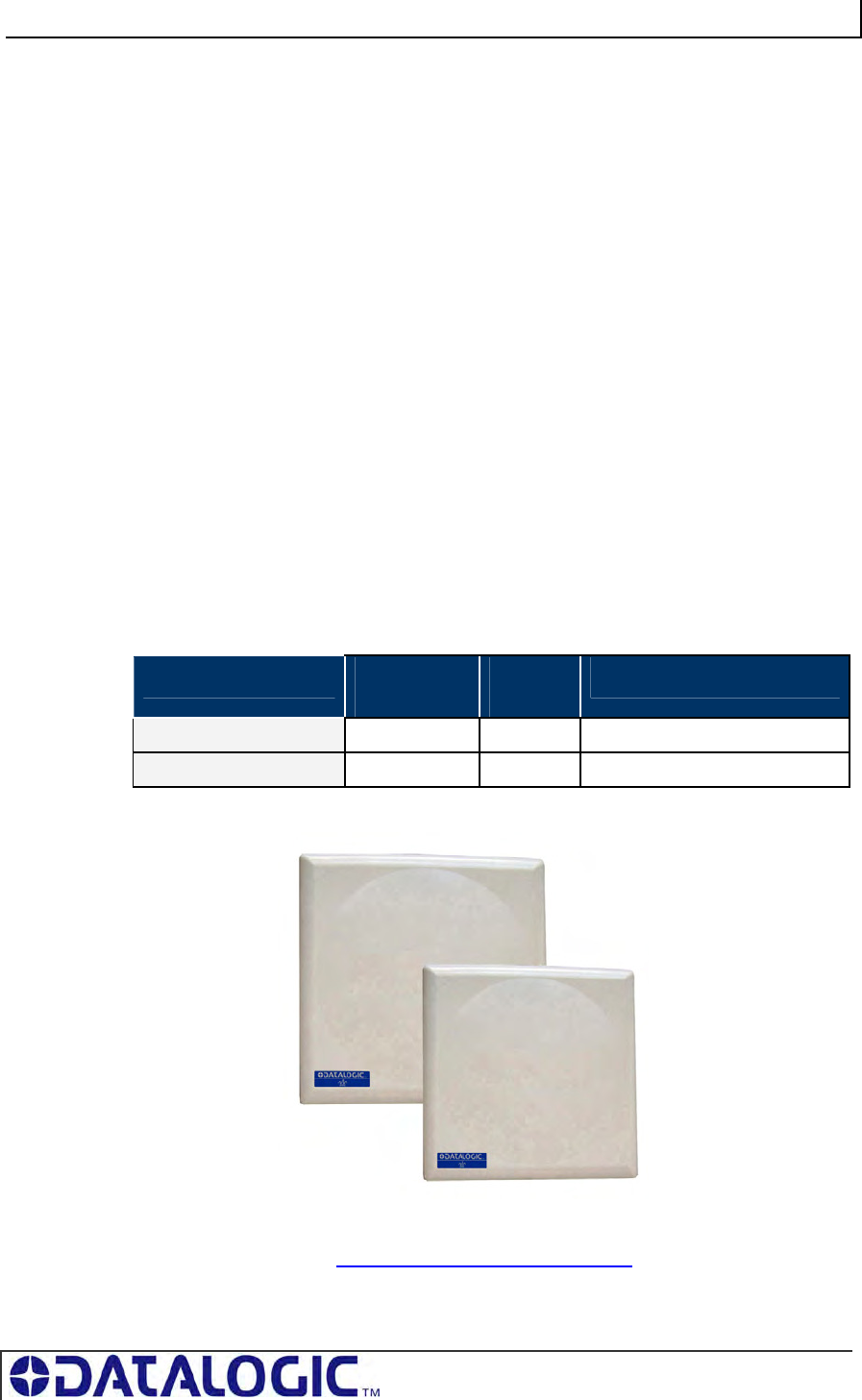
1.4.2 Cobalt UHF RFID Antennas - Models and Sizes
The Cobalt UHF product family includes two RFID antenna models:
UHF-ANT-2626-01-86 for operating frequencies in the 865-870 MHz UHF ranges
UHF-ANT-3030-01-91 for operating frequencies in the 902-928 MHz UHF ranges
Please refer to the table below for antennas’ dimensions and part numbers:
ANTENNA MODEL ANTENNA
P/N
UHF
FREQ
ANTENNA SIZE
UHF-ANT-2626-01-86 970669001 868MHz 260 x 260mm (10.2 x 10.2 inch)
UHF-ANT-3030-01-91 970665003 915MHz 305 x 305mm (12 x 12 inch)
Table 1-4: Cobalt UHF RFID Antennas - Models and Sizes
The two Cobalt UHF RFID Antennas are compatible with all Cobalt UHF-Series RFID
Controller models (see Appendix B - Models & Accessories).
COBALT UHF-SERIES CHAPTER 1: GETTING STARTED
PAGE 18 OF 140
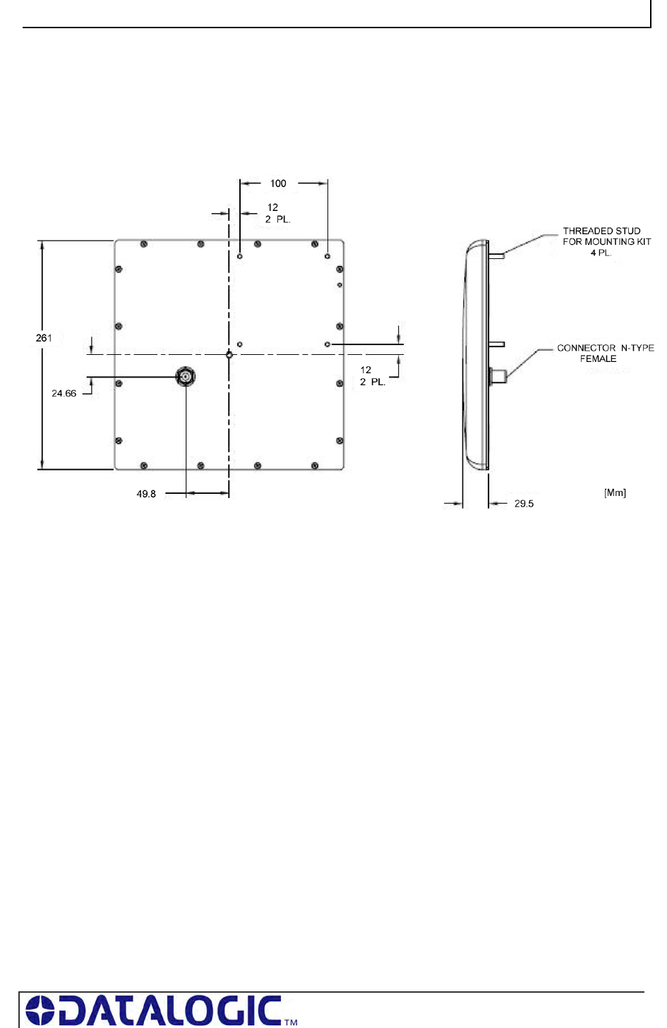
1.4.3 UHF-ANT-2626-01-86 Antenna Dimensions
Figure 1-4: UHF-ANT-2626-01-86 Antenna Dimensions
COBALT UHF-SERIES CHAPTER 1: GETTING STARTED
PAGE 19 OF 140
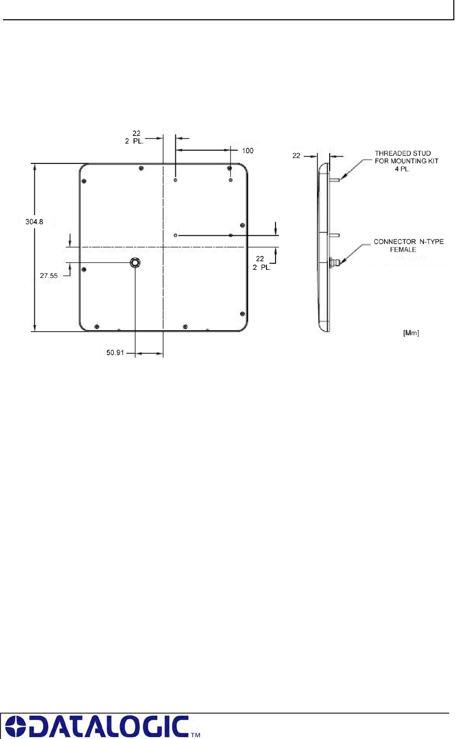
1.4.4 UHF-ANT-3030-01-91 Antenna Dimensions
Figure 1-5: UHF-ANT-3030-01-91 Antenna Dimensions
COBALT UHF-SERIES CHAPTER 1: GETTING STARTED
PAGE 20 OF 140
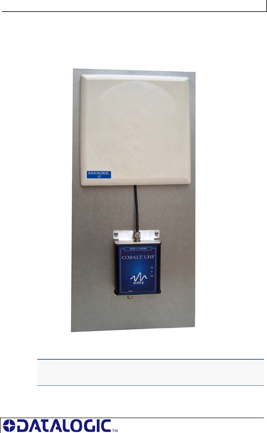
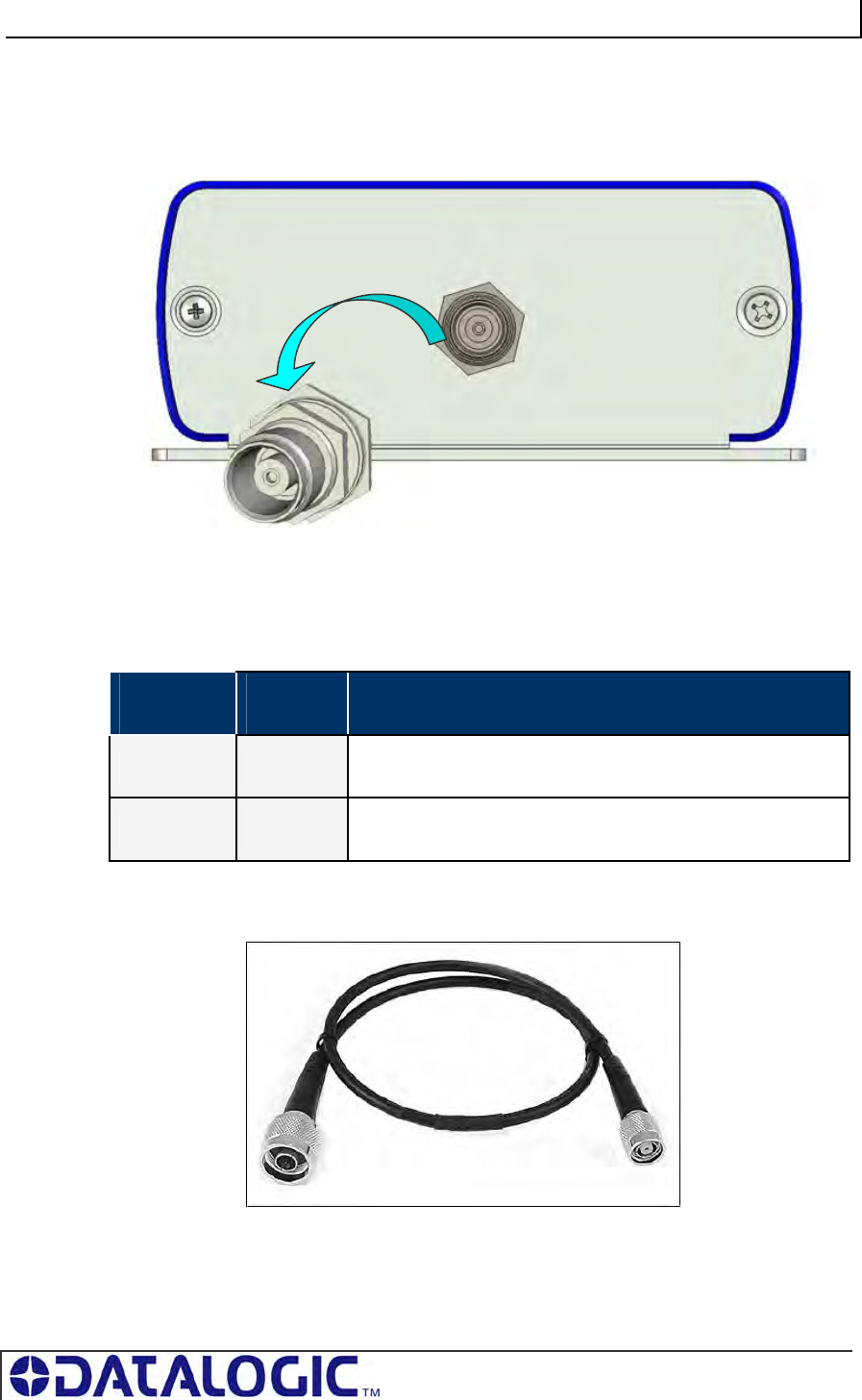
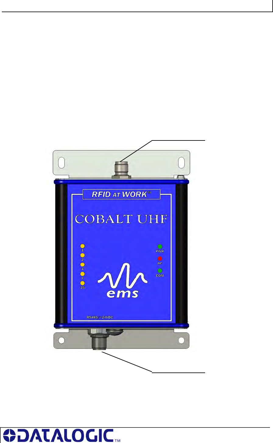
1.4.5 Connecting the Antenna to the Controller
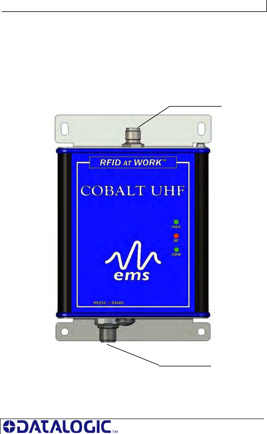
The Cobalt UHF Antennas are connected to the top of the Cobalt UHF-Series RFID
Controller’s housing through a single coaxial cable.
Figure 1-6: Connecting the Antenna to the Controller
The Cobalt UHF antenna has one female, N-type connector located on its rear side.
The Cobalt UHF Controller has one TNC-Reverse female connector located on the
top of the Controller’s housing.
COBALT UHF-SERIES CHAPTER 1: GETTING STARTED
PAGE 21 OF 140
The RF port on the Cobalt UHF controller connects directly to the RF port on the
Cobalt UHF antenna via a compatible antenna feeder cable (see Table 1-6 below for
cabling information).
Figure 1-7: TNC-Reverse Female Connector for Antenna Feeding
For cabling part numbers and descriptions, please refer to the table below:
CABLE
MODEL CABLING
P/N DESCRIPTION
UHF-CBL-01 970106002 Coaxial Cable Controller-Antenna, TNC-Reverse Male to N-
Type Male, 1 meter
UHF-CBL-03 970106003 Coaxial Cable Controller-Antenna, TNC-Reverse Male to N-
Type Male, 3 meters
Table 1-5: Controller-Antenna Cabling Information
Figure 1-8: UHF-CBL-0X - Controller-Antenna Coaxial Cable
COBALT UHF-SERIES CHAPTER 1: GETTING STARTED
PAGE 22 OF 140
To connect the Cobalt UHF controller to the antenna, follow the steps below:
Attach the TNC-Reverse male plug of the controller-antenna coaxial cable to
the TNC- Reverse female connector located on the top of the controller’s
housing.
Attach the N-type male plug of the coaxial cable to the N-type female
connector located in the rear of the antenna’s body.
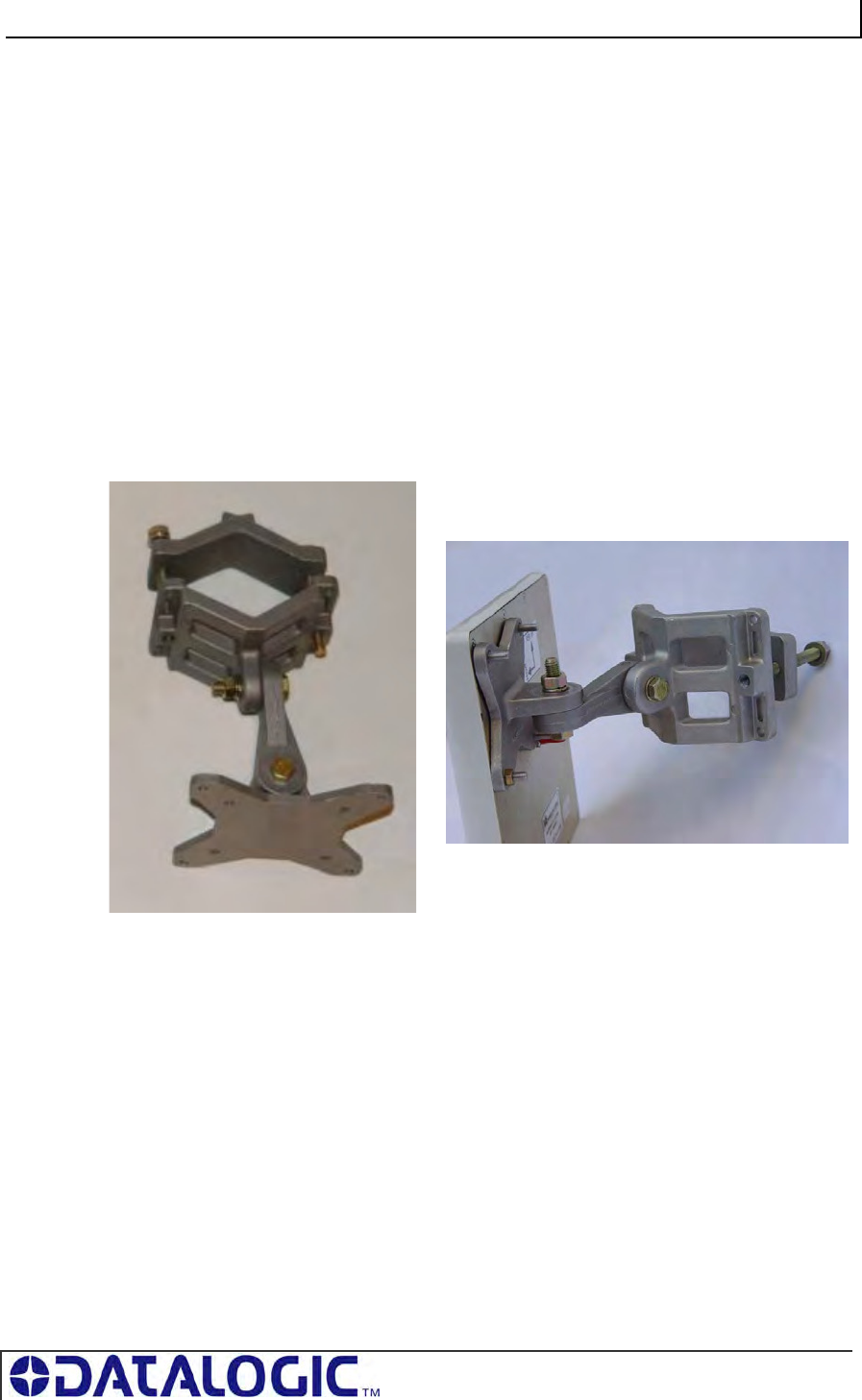
1.4.6 Optional Mounting Kit for Antenna Installation
Industrial environments where UHF RFID applications are used often entail specific
installation requirements.
The Cobalt UHF Antenna can take advantage of an optional mounting set, providing
an easy and solid installation (P/N: 970103035, Mounting Kit for large size UHF
Antennas).
Figure 1-9:Optional Mounting Kit for Antennas
COBALT UHF-SERIES CHAPTER 1: GETTING STARTED
PAGE 23 OF 140
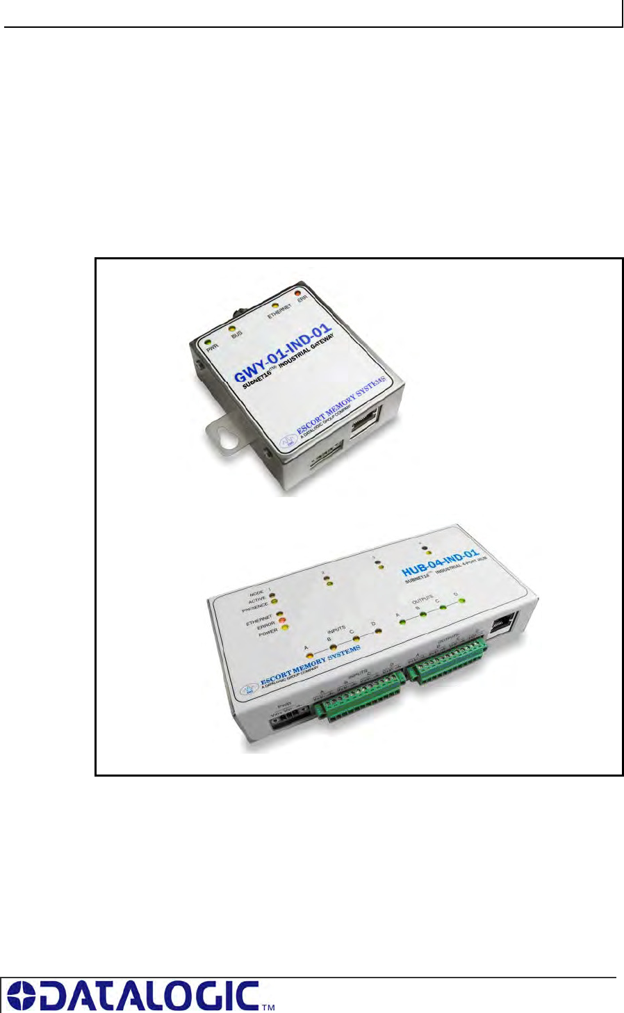
1.5 SUBNET16™ MULTIDROP PROTOCOL
The UHF-CNTL-485-02 model includes support for Escort Memory Systems’
Subnet16™ Multidrop RFID networking protocol. Under the Subnet16 protocol, up to
16 UHF-CNTL-485-02 controllers can be connected via a trunk and tap network to a
Subnet16 Industrial Gateway (GWY-01-IND-1), a Subnet16 TCP/IP Gateway (GWY-
01-TCP-01) or a Subnet16 Serial Gateway (GWY-01-232-1).
UHF-CNTL-485-02 models can also be connected directly to a Subnet16 Industrial
Hub (HUB-04-IND-01) or Subnet16 TCP/IP Hub (HUB-04-TCP-01). Subnet16 Hubs
possess four independent controller ports, four digital inputs and four digital outputs.
Figure 1-10: Subnet16™ Industrial Gateway and Industrial Hub
COBALT UHF-SERIES CHAPTER 2: INSTALLING THE COBALT UHF
PAGE 24 OF 140
CHAPTER 2:
INSTALLING THE COBALT UHF
2.1 PREPARING FOR INSTALLATION
The Cobalt UHF-Series RFID Controllers support point-to-point serial connections
(RS232 and RS485), multi-drop network connections (via Subnet16™ Gateway or
Hub) and Ethernet connections (TCP/IP, Ethernet/IP, Modbus TCP).
NOTE: Up to 16 UHF-CNTL-485-02 units can be networked via Subnet16 Gateway
interface module and Escort Memory Systems’ Subnet16 Multidrop Bus Architecture.
2.1.1 Power Requirements
The Cobalt UHF Controller requires an electrical supply voltage of 10~30VDC (see
Appendix A: Technical Specifications).
Use a dedicated and regulated power supply connected to a suitable AC power
source that is capable of delivering these requirements. Do not apply power until the
entire system is wired and checked.
See Appendix B: Models & Accessories – Power Supplies for a list of available power
supplies.
2.1.2 Installation Guidelines
Conduct a test phase where you will construct a small scale, independent
network that includes only the essential devices required to test your RFID
application. To avoid possible interference with other devices, do not initially
connect your RFID testing environment to an existing local area network.
RF performance and read/write range can be negatively impacted by the
proximity of metallic objects and liquids (for further information, refer to Section
9.2.2 “UHF Signal Propagation”). Avoid mounting the Cobalt antenna within
15cm (6 inches) of any metallic object or wet surface.
If electrical interference is encountered (as indicated by a reduction in read/write
performance), relocate the controller/antenna to an area free from potential
sources of interference.
Route cables away from other unshielded cables and away from wiring carrying
high voltage or high current. Avoid routing cables near motors and solenoids.
Always use adequate electro-static discharge (ESD) prevention measures to
dissipate potentially high voltages.
Refrain from mounting the controller/antenna near sources of EMI (electro-
magnetic interference) or near devices that generate high ESD levels.
COBALT UHF-SERIES CHAPTER 2: INSTALLING THE COBALT UHF
PAGE 25 OF 140
2.2 INSTALLING THE UHF-CNTL-232-02
The UHF-CNTL-232-02 RFID Controller is designed for point-to-point RFID
applications, where the distance from host to controller is less than 15 meters (50
feet). The controller connects directly to a serial communications port on a host
computer via an RS232-compatible serial interface cable.
Figure 2-1: UHF-CNTL-232-02 Communication Interfaces
TO RS232 HOST
CONNECTOR
TO ANTENNA
COBALT UHF-SERIES CHAPTER 2: INSTALLING THE COBALT UHF
PAGE 26 OF 140
2.2.1 Steps to Install the UHF-CNTL-232-02
1. Select a suitable location for the Cobalt UHF Controller/Antenna.
2. Attach the Cobalt UHF Antenna to the Cobalt UHF Controller, as described in
Section 1.4.5 “Connecting the Antenna to the Controller”.
3. Fasten the combined controller and antenna to your mounting fixture using two
M5 (#10) diameter screws (not included) and secure them with appropriate
washers and nuts. Tighten screws to 1.7 Nm or 15 lbs per inch ± 10%.
4. Connect the 8-pin, female M12 connector from an RS232-compatible serial
interface cable (EMS P/N: CBL-1478) to the 8-pin, male M12 interface connector
on the Cobalt UHF-CNTL-232-02.
5. Connect the 9-pin, female D-sub connector on the serial interface cable to a
COM port on a host computer. Tighten the cable’s two locking thumbscrews.
6. Connect the 2.5mm DC power plug on the power supply transformer to the DC
power jack receptacle on the serial interface cable. Tighten the locking ring to
prevent power from becoming disconnected during use.
7. Plug the power supply transformer into a suitable AC power source. Apply power
to the controller after all cable connections have been made. The green PWR
(power) LED will remain ON while the Cobalt is powered.
8. On the host computer, set COM port parameters to the following values:
T
Table 2-1: COM Port Parameter Defaults (UHF-CNTL-232-02)
*Supported baud rates include 9600, 19.2k, 38.4k, 57.6k, and 115.2k.
9. To verify operations, download the Cobalt Dashboard Utility from Escort
Memory Systems’ website (www.ems-rfid.com). The Cobalt Dashboard Utility
allows users to configure their Cobalt UHF Controllers and send RFID
commands for testing purposes. Please refer to Section 3.1 “Configuring the
Cobalt via Dashboard Utility” for some generic Cobalt UHF configuration
examples.
COM PORT PARAMETER DEFAULT VALUE
Baud Rate 9600*
Parity None
Data Bits 8
Stop Bits 1
Handshaking None
COBALT UHF-SERIES CHAPTER 2: INSTALLING THE COBALT UHF
PAGE 27 OF 140
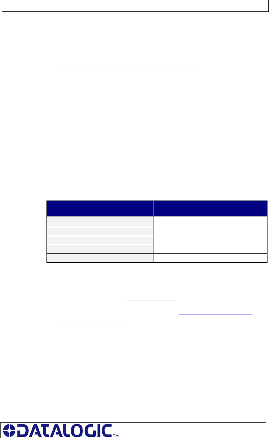
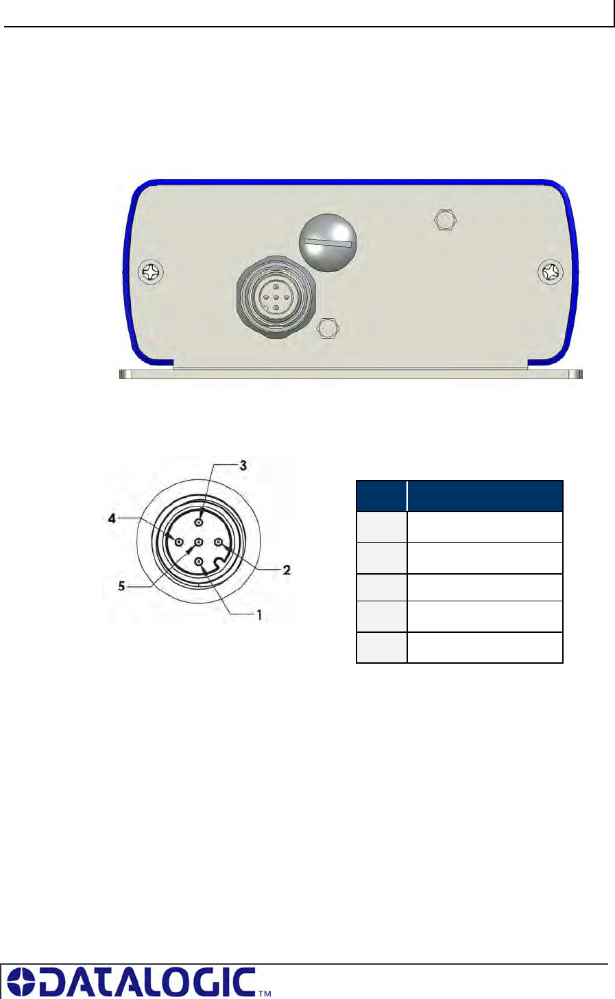
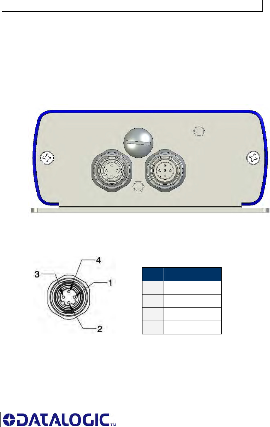
2.2.2 UHF-CNTL-232-02 Cabling Information
The UHF-CNTL-232-02 has one 8-pin, male M12 RS232 connector located on the
bottom of the Controller’s housing.
Figure 2-2: UHF-CNTL-232-02 Controller - RS232 Connector
Table 2-2: RS232 Connector - Pinout
UHF-CNTL-232-02 CABLING PART NUMBERS
CBL-1478: Cable Assembly (8-pin, female M12 to RS232; with 2.5mm DC power
jack, 2m)
CBL-1488-XX: Cable (8-pin, female M12 to bare wire leads)
CBL-1492-XX: Cable (8-pin, right-angle female M12 to bare wire leads)
CBL-1493: Connector (8-pos, straight female M12, field mountable)
(XX = Cable Length in Meters)
PIN # DESCRIPTION
1 10~30VDC POWER
2 0VDC (POWER GROUND)
3 NOT CONNECTED
4 NOT CONNECTED
5 NOT CONNECTED
6 RX
7 TX
8 SGND (SIGNAL GROUND)
COBALT UHF-SERIES CHAPTER 2: INSTALLING THE COBALT UHF
PAGE 28 OF 140
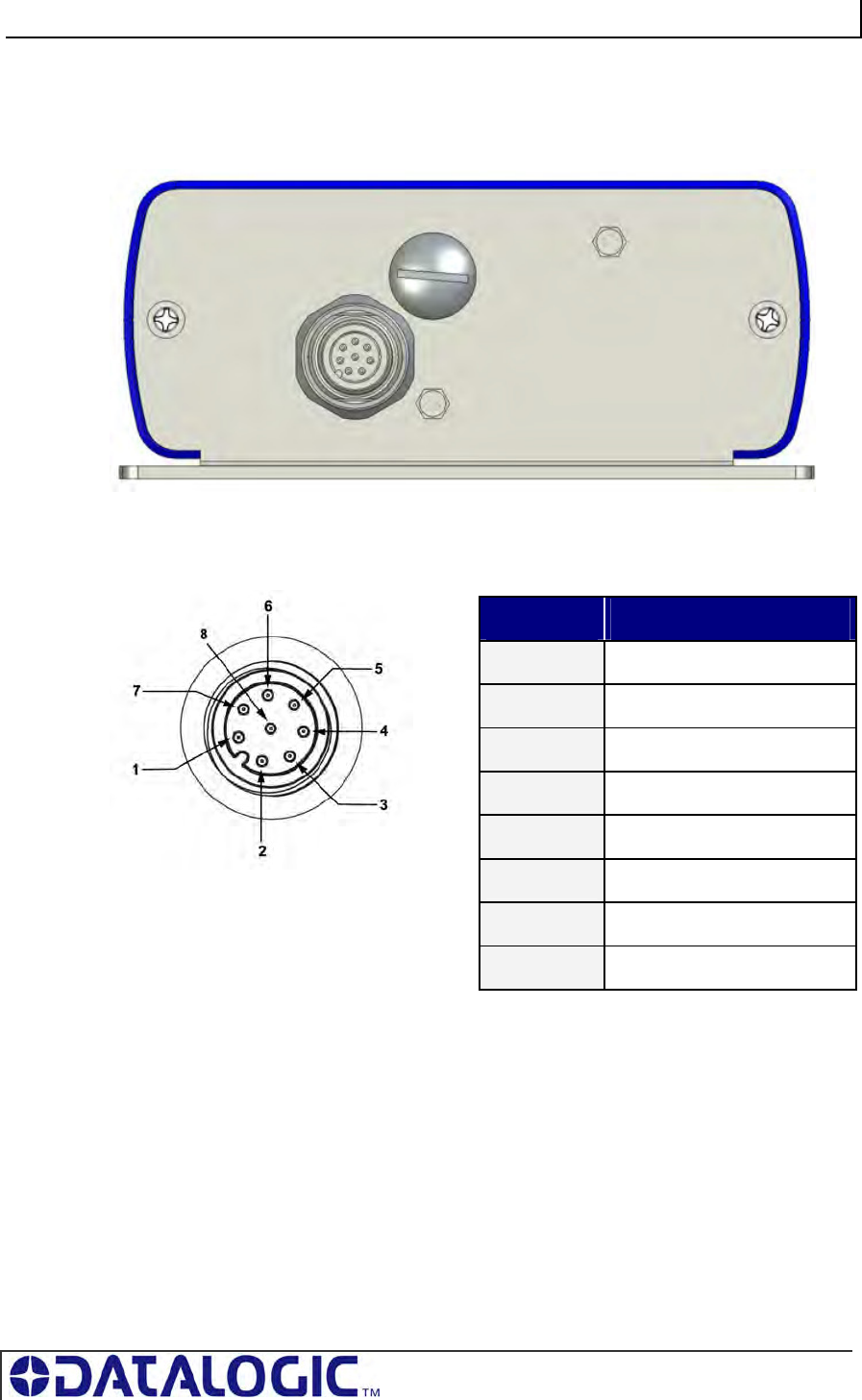
RS232 SERIAL INTERFACE CABLE SCHEMATIC
If you intend to assemble your own RS232 serial interface cable, follow the schematic
below. Note that signals and electrical loads applied to Pin 6 (RX) and Pin 7 (TX)
should conform to RS232 specifications. For bulk RS232 cable, see Belden cable
P/N: 9941 (www.belden.com).
Figure 2-3: RS232 Serial Interface Cable – Schematic
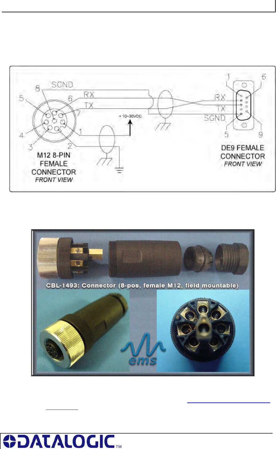
CBL-1493: FIELD MOUNTABLE CONNECTOR
Figure 2-4: CBL-1493 Mountable Connector
The CBL-1493 field mountable connector is available for attaching the UHF-CNTL-
232-02 model to a host computer via bulk cable. See Appendix B: Cobalt Cables and
Accessories for more information regarding cables and connectors for the entire line
of Cobalt UHF RFID Controllers.
COBALT UHF-SERIES CHAPTER 2: INSTALLING THE COBALT UHF
PAGE 29 OF 140
2.3 INSTALLING THE UHF-CNTL-485-02
The UHF-CNTL-485-02 RFID Controller supports RS485 communications and Escort
Memory Systems’ Subnet16™ multi-drop bus architecture and RFID network
protocol.
Through the Subnet16 protocol, up to 16 UHF-CNTL-485-02 units can be connected
to one Subnet16 Gateway and four UHF-CNTL-485-02 units can be connected to
one Hub interface module. Subnet16 Gateways and Hubs assign each attached
controller a unique Node ID number through which communication with a host
computer and/or Programmable Logic Controller (PLC) is achieved.
For applications that require multiple UHF-CNTL-485-02 controllers, install and
configure each device one at a time.
Figure 2-5: UHF-CNTL-485-02 Communication Interfaces
TO SUBNET16
NETWORK
TO ANTENNA

COBALT UHF-SERIES CHAPTER 2: INSTALLING THE COBALT UHF
PAGE 30 OF 140
2.3.1 Steps to Install the UHF-CNTL-485-02
1. Select a suitable location for the Cobalt UHF Controller/Antenna.
2. Attach the Cobalt UHF Antenna to the Cobalt UHF Controller, as described in
Section 1.4.5 “Connecting the Antenna to the Controller”.
3. Fasten the combined controller and antenna to your mounting fixture using two
M5 (#10) diameter screws (not included) and secure them with appropriate
washers and nuts. Tighten screws to 1.7 Nm or 15 lbs per inch ± 10%.
4. Connect the 5-pin, female end of an EMS approved Subnet16-compatible cable
to the 5-pin, male M12 interface connector on the UHF-CNTL-485-02. Connect
the opposite end of this cable to a Subnet16 Gateway or Subnet16 Hub network
interface module. Connect the Gateway or Hub to your host computer via CAT5E
Ethernet cabling.*.
5. The UHF-CNTL-485-02 will require 10~30VDC (see Appendix A: Technical
Specifications) from the network or interface module to which it is
connected.Utilize a regulated power supply for the controller that is capable of
delivering these requirements.
6. Turn the power supply ON. The green PWR (power) LED on the unit will
illuminate when power is applied to the unit and remain ON while the Cobalt is
powered.
7. After installation is complete (see also Sections 3.3.2 and 3.3.3), the yellow Node
ID LEDs will display the currently assigned Subnet16 Node ID (in binary). Note:
the Cobalt’s default Node ID is Node 00; in which case none of the yellow Node
ID LEDs will be lit.
8. To verify operations, download the Cobalt Dashboard Utility from Escort Memory
Systems’ website (www.ems-rfid.com). The Cobalt Dashboard Utility allows
users to configure their Cobalt UHF Controllers and send RFID commands for
testing purposes. Please refer to Section 3.1 “Configuring the Cobalt via
Dashboard Utility” for some generic Cobalt UHF configuration examples.
* For more information regarding the installation of a Subnet16 Gateway or
Subnet16 Hub, refer to the operator’s manual for each product, available online
at www.ems-rfid.com.
COBALT UHF-SERIES CHAPTER 2: INSTALLING THE COBALT UHF
PAGE 31 OF 140
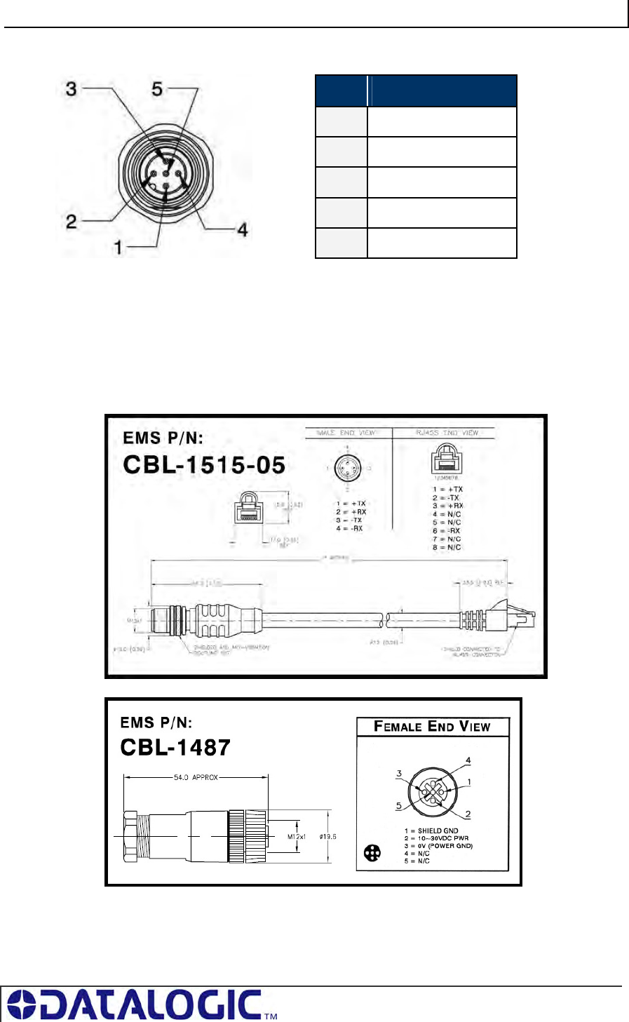
2.3.2 UHF-CNTL-485-02 Cabling Information
The UHF-CNTL-485-02 has one 5-pin, male M12 RS485 connector located on the
bottom of the Controller’s housing.
Figure 2-6: UHF-CNTL-485-02 Controller - RS485 Connector
Table 2-3: RS485 Connector – Pinout
UHF-CNTL-485-02 CABLING PART NUMBERS
CBL-1480-XX: Cable (5-pin, male M12 to 5-pin, female M12, ThinNet)
CBL-1481-XX: Cable (5-pin, male M12 to 5-pin, male M12, ThinNet)
(XX = Cable Length in Meters)
PIN # DESCRIPTION
1 SIGNAL GND
2 10~30VDC PWR
3 0V (POWER GND)
4 Tx/Rx+
5 Tx/Rx-
COBALT UHF-SERIES CHAPTER 2: INSTALLING THE COBALT UHF
PAGE 32 OF 140
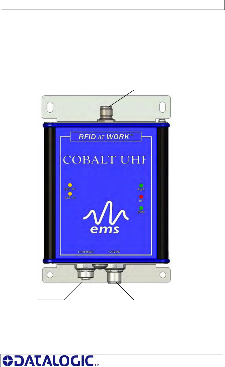
2.4 INSTALLING THE UHF-CNTL-IND-02
The UHF-CNTL-IND-02 RFID Controller supports TCP/IP and Industrial Ethernet
communications. The UHF-CNTL-IND-02 can be connected to a LAN or
Programmable Logic Controller (PLC) via CAT5E Ethernet cabling or it can be
connected directly to a host computer by means of a standard Ethernet crossover
cable.
Figure 2-7: UHF-CNTL-IND-02 Communication Interfaces
TO ANTENNA
TO ETHERNET
NETWORK TO MAINS
COBALT UHF-SERIES CHAPTER 2: INSTALLING THE COBALT UHF
PAGE 33 OF 140
2.4.1 Steps to Install the UHF-CNTL-IND-02
1. Select a suitable location for the Cobalt UHF Controller/Antenna.
2. Attach the Cobalt UHF Antenna to the Cobalt UHF Controller, as described in
Section 1.4.5 “Connecting the Antenna to the Controller”.
3. Fasten the combined controller and antenna to your mounting fixture using two
M5 (#10) diameter screws (not included) and secure them with appropriate
washers and nuts. Tighten screws to 1.7 Nm or 15 lbs per inch ± 10%.
4. Connect the three wires from your power supply to pins 1-3 on the 5-pin, female,
M12 connector (P/N: CBL-1487).
5. Attach the CBL-1487 connector to the 5-pin, male, M12 connector on the Cobalt
Controller.
6. Attach the 4-pin, male, M12, D-Code connector from a CAT 5E (or better)
industrial Ethernet cable (P/N: CBL-1515-05) to the 4-pin, female, M12, D-Code
connector on the Cobalt Controller.
7. Connect the other RJ45S end of the CBL-1515-05 cable to your application
network or LAN. A crossover cable may be required if you are connecting the
Cobalt directly to a host computer (rather than to a switch, hub or router).
8. Turn the power supply ON. The green Power LED on the unit will illuminate.
9. After installation is complete, the amber Default IP LED will be lit when the
controller is operating using its default IP address. The amber Actual IP LED will
be lit when the controller is operating with a user assigned IP address.
UHF-CNTL-IND-02 Default IP Address:
192.168.253.110
10. To verify operations, download the Cobalt Dashboard Utility from Escort Memory
Systems’ website (www.ems-rfid.com). The Cobalt Dashboard Utility allows
users to configure their Cobalt UHF Controllers and send RFID commands for
testing purposes. Please refer to Section 3.1 “Configuring the Cobalt via
Dashboard Utility” for some generic Cobalt UHF configuration examples.
COBALT UHF-SERIES CHAPTER 2: INSTALLING THE COBALT UHF
PAGE 34 OF 140
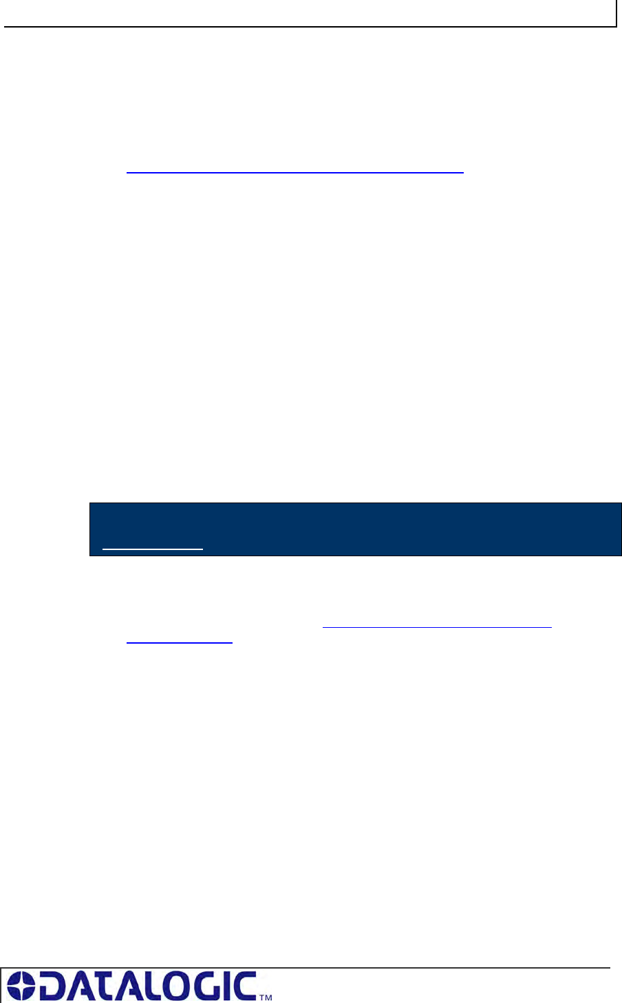
2.4.2 UHF-CNTL-IND-02 Cabling Information
The UHF-CNTL-IND-02 includes:
a 4-pin, female M12, D-code connector for Ethernet communication
a 5-pin, male M12 connector for power.
These connectors are located on the bottom of the Controller’s housing.
Figure 2-8: UHF-CNTL-IND-02 Controller - Ethernet & Power Connectors
Table 2-4: Ethernet Connector - Pinout
PIN # DESCRIPTION
1 TX+
2 RX+
3 TX-
4 RX-
COBALT UHF-SERIES CHAPTER 2: INSTALLING THE COBALT UHF
PAGE 35 OF 140
Table 2-5: Power Connector - Pinout
UHF-CNTL-IND-02 CABLING PART NUMBERS
CBL-1515-05: Cable Assembly (CAT5E, RJ45S to 4-pin, male M12, D- Code, 5m)
CBL-1487: Field Mountable Connector (5-pos, female M12)
PIN # DESCRIPTION
1 NOT CONNECTED
2 10~30VDC POWER
3 0VDC (POWER GROUND)
4 NOT CONNECTED
5 NOT CONNECTED
COBALT UHF-SERIES CHAPTER 3: CONFIGURING THE COBALT
PAGE 36 OF 140
CHAPTER 3:
CONFIGURING THE COBALT UHF
Stored in the Cobalt’s flash memory is a group of settings, attributes and parameters
known as the “Controller Configuration.” These parameters are related to the
communication protocol and operating mode.
The controller configuration can be modified by using Escort Memory Systems’
Cobalt Dashboard Utility (which can be downloaded from www.ems-rfid.com) or
through the use of a Cobalt UHF Configuration Tag (included with each Cobalt
Controller).
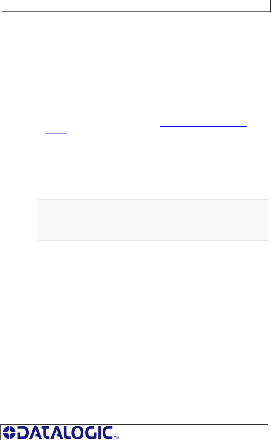
3.1 CONFIGURING THE COBALT VIA DASHBOARD UTILITY
The Cobalt Dashboard Utility is a software application that allows users to view,
modify, save and update the configuration settings of their Cobalt controllers.
Download the Cobalt Dashboard from www.ems-rfid.com and follow the instructions
included with the software to install and operate the utility and to set the controller’s
configuration.
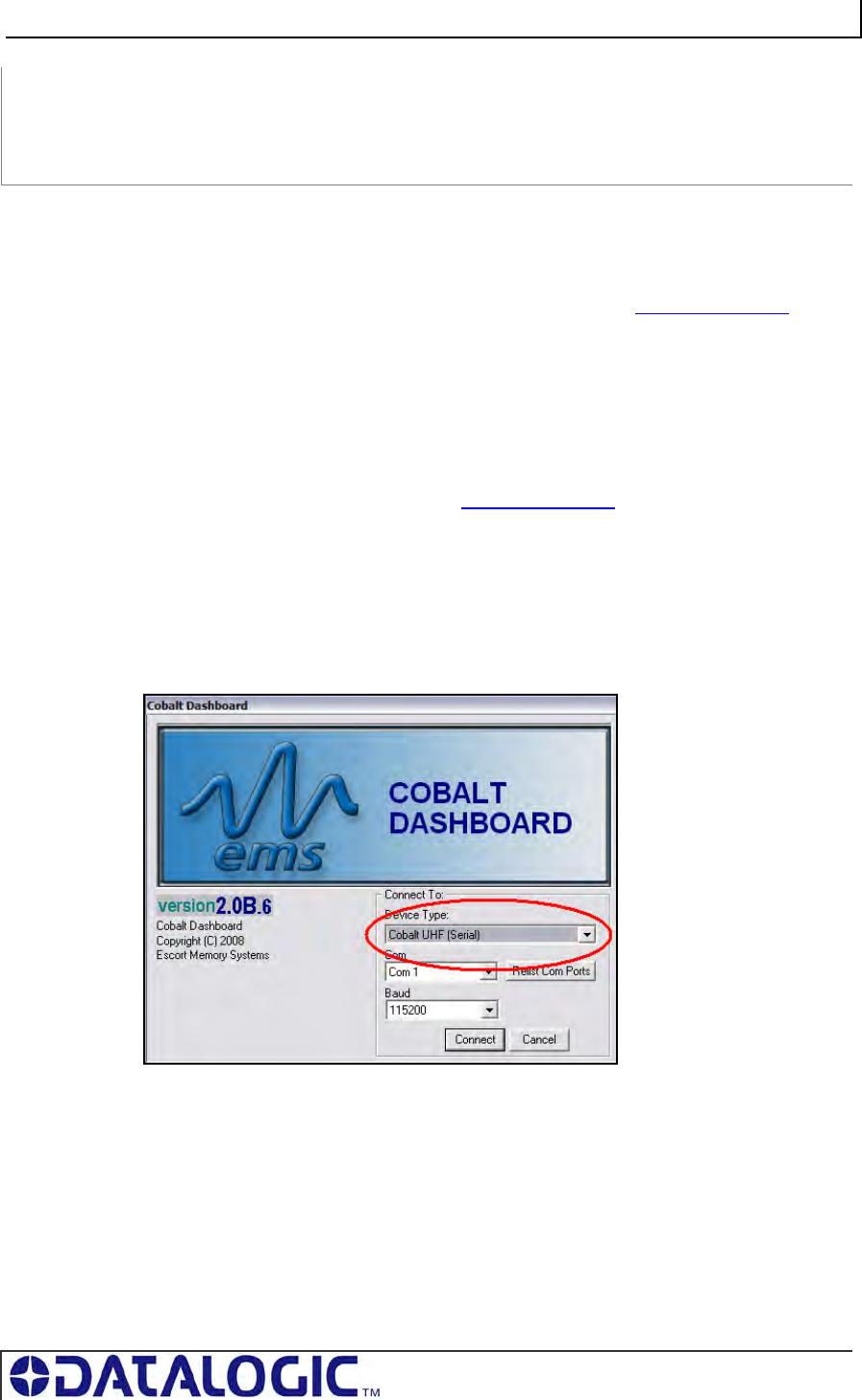
The Cobalt Dashboard configuration utility is a general purpose software that can be
used with all the Cobalt family devices, including HF controllers and Gateways. To
use it with the UHF Series Controller you need to properly select the model at
startup. For example, in this case the Cobalt UHF Serial controller is selected:
Once the connection is established, you will see the normal startup screen of the
Dashboard utility. For more information on the Dashboard please see the manual that
you can find on the web site.
COBALT UHF-SERIES CHAPTER 3: CONFIGURING THE COBALT
PAGE 37 OF 140
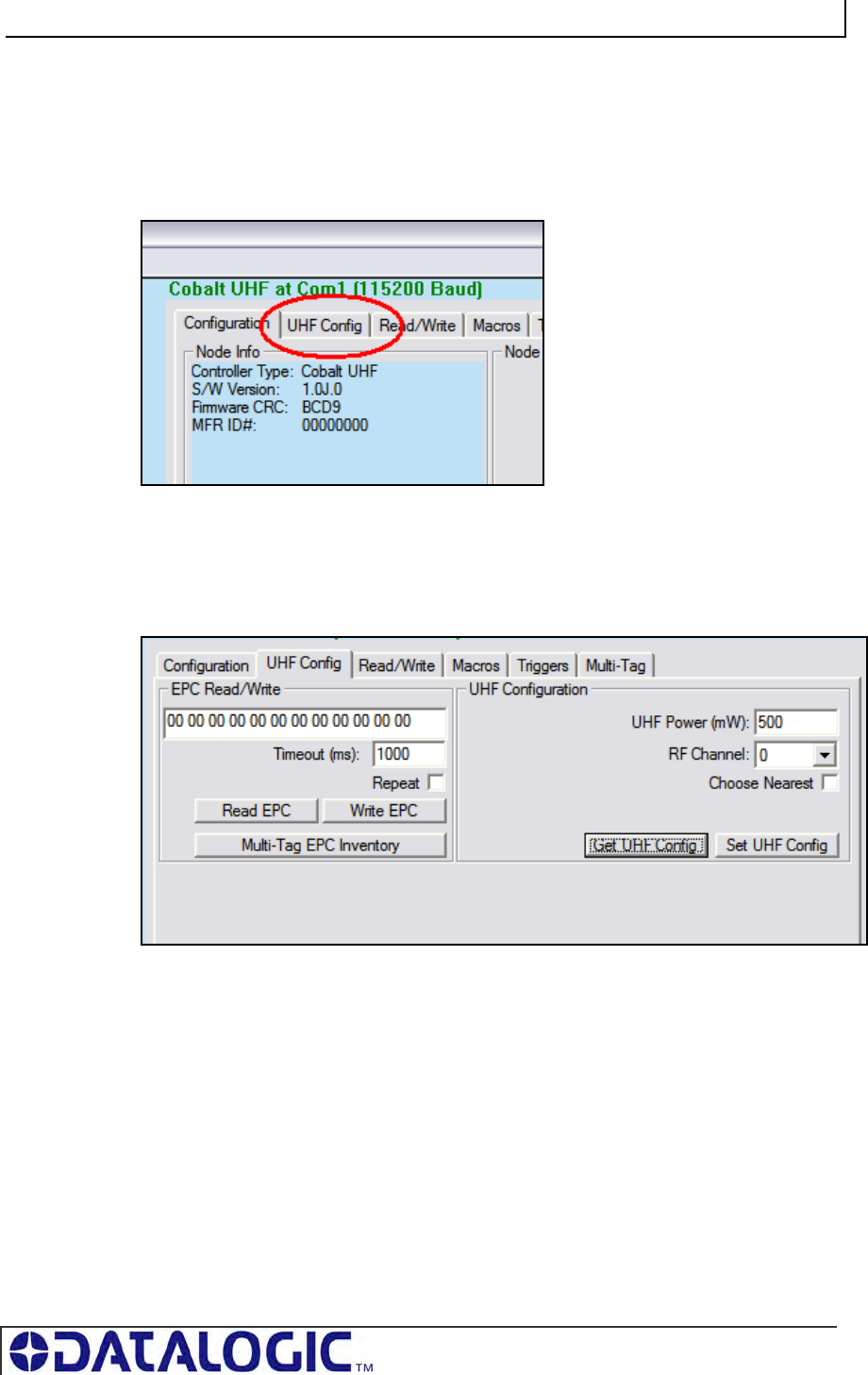
COBALT UHF CONFIGURATION EXAMPLE: UHF CONFIGURATION TAB
One of the five different tabs shown in the Dashboard’s main display is the UHF
Configuration Tab.
This tab contains two different sections: EPC Read/Write and UHF Configuration
Section. These sections provide configuration details and contains parameter options
related to the UHF controller’s specific features.
In the EPC Read/Write section, for instance, users can read and write the EPC
portion of the UHF tags and also do an inventory of the ECP codes of all the tags in
the field of the reader. Setting the Repeat option will make the Dashboard
continuously sending the same command.
The UHF Configuration section allows users to set configuration parameters which
are specific to the UHF controller, namely:
UHF Power, representing the RF power in mW emitted during the
communication with tags
RF Channel, a 2-bytes value in the range 0-9 representing the RF channel to
use (this has a meaning only on the EU frequency reader)
COBALT UHF-SERIES CHAPTER 3: CONFIGURING THE COBALT
PAGE 38 OF 140
Choose Nearest, Instruct the reader to return only the information of the tag
with the stronger signal, which can be assumed is the “nearest” in space,
even if in real world condition this might be not always true.
Furthermore, users may retrieve or set the desired UHF configuration settings by
clicking on the buttons “Get UHF Config” and “Set UHF Config”.
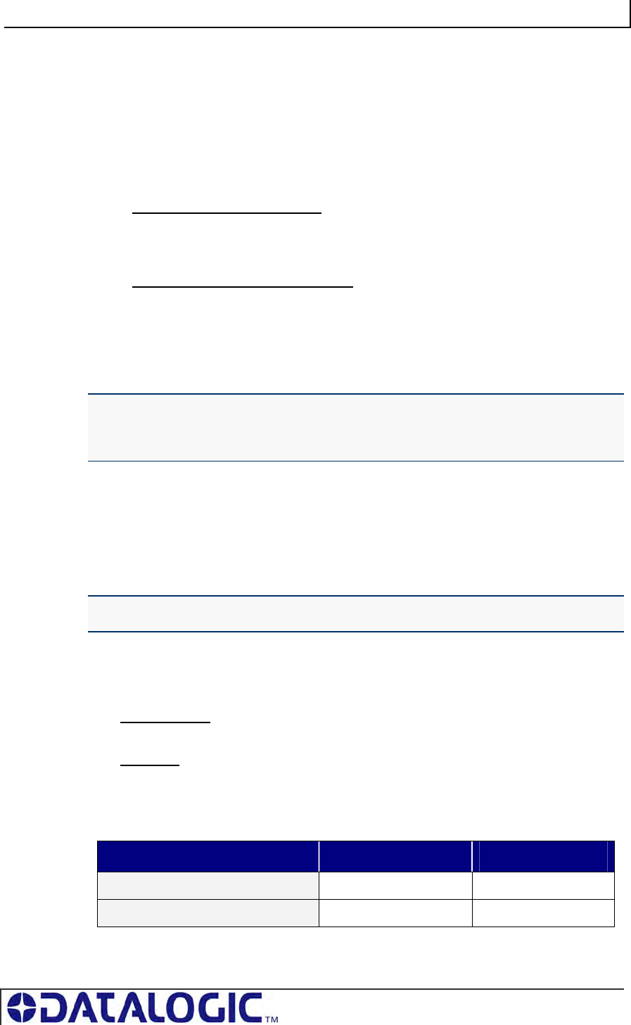
3.2 NOTE ABOUT THE READER POWER
The performance of a UHF reader depends on the radiated power, not simply on the
reader output power that can be set with the above parameter. The radiated power
depends on the reader output power, the cable attenuation and the antenna gain.
The radiated power limits are set by the different governments (see table below for
details).
REGION REGULATIONS RADIATED POWER
USA FCC Part 15 4 W EIRP (36 dBm)
Europe EN 302 208 2 W ERP (35 dBm)
Table 3-1:Reader Radiated Power Limits
The UHF-CNTL-XXX-02 controllers produce up to 500 mW output power.
EXAMPLE OF A CALCULATION:
Radiated Power = Reader Power + Antenna Gain – Cable Losses
500 mW (27dBm) + 6.85 dBi - 1.5dBm = 32.35 dBm (~1.7 W ERP)
3.3 CONFIGURING THE COBALT VIA “CONFIGURATION
TAG”
As noted, the Cobalt UHF controllers are software configurable via the Cobalt
Dashboard Utility. However, they can also be configured through the use of the
Cobalt UHF Configuration Tag supplied with each unit.
The Configuration Tag can be used to restore the factory default values for all
versions of the Cobalt UHF RFID Controller.
3.3.1 Restoring Factory Defaults
1. Place the Configuration Tag in the antenna’s RF field.
2. Cycle power to the controller or issue the “Reset Controller” command
(Command 0x35).
As power returns to the unit, the LEDs will blink.
3. After the LEDs blink, remove the Configuration Tag from the antenna’s RF field.
Factory default values have been restored.
COBALT UHF-SERIES CHAPTER 3: CONFIGURING THE COBALT
PAGE 39 OF 140
The following factory default values will be restored on the controller:
CONFIGURATION PARAMETER FACTORY DEFAULT VALUE
Continuous Read Mode Disabled
Macros and Triggers Erased
UHF Power
RF channel
Choose Nearest
500 mW
0
Disabled
RS232 - Serial Communications
RS485 - Node ID
IND – TCP/IP Address
9600, N, 8, 1, N
0
192.168.253.110
Table 3-2: Configuration Tag – Restored Factory Defaults
3.3.2 Manually Assigning Node ID (Cobalt -485 Model
Only)
On the UHF-CNTL-485-02, the five amber Node LEDs display (in binary notation) the
numerical Node ID value of the controller. For example, if Node LEDs 1, 2 and 8 are
ON, the controller has been assigned Node ID 11.
Follow the steps below to assign a Node ID value manually to an UHF-CNTL-485-02.
1. Place the Configuration Tag in the antenna’s RF field.
2. Cycle power to the controller or issue the “Reset Controller” command
(Command 0x35 for ABx Fast, Command 0x54 for CBx).
As power returns to the unit, the LEDs will blink.
3. Remove the Configuration Tag from the antenna’s RF field and then immediately
place it back within antenna range. Verify that all five amber Node LEDs are OFF
(indicating that the controller’s Node ID was reset to zero).
4. With all amber Node LEDs OFF, remove the Configuration Tag from the
antenna’s RF field and then immediately place it back in the antenna’s RF field to
increment the Node ID value by one (from Node ID 00 to 01, in this case). The
lone amber Node 1 LED will illuminate to indicate that Node 01 is selected.
5. You may repeat Step 4 until the desired Node ID number is reached. The value
is incremented by one each time a Configuration Tag is withdrawn from and re-
introduced to the Cobalt HF Antenna’s RF field. This procedure can be used to
cycle through all 16 possible Node ID values. Note that after reaching Node ID
16, incrementing the value once more returns the selected Node ID number to
zero.
6. After setting the desired Node ID, remove the Configuration Tag from the RF field
and allow approximately 10 seconds for the unit to reset and resume operation
under its new Node ID value.
COBALT UHF-SERIES CHAPTER 3: CONFIGURING THE COBALT
PAGE 40 OF 140
3.3.3 Automatic Node ID Assignment via Gateway
(Cobalt -485 Model Only)
For multi-drop network configurations (where up to 16 Cobalt UHF-CNTL-485-02
controllers are connected via one Subnet16 Gateway interface module), a Gateway
module can be instructed, through the use of a Configuration Tag, to automatically
assign each controller a separate Node ID number (between 1 and 16).
However, before the Gateway can begin allocating Node IDs automatically, each
UHF-CNTL-485-02 controller must first be restored to factory default values. In doing
so, the Cobalt’s Node ID number will be reset to zero.
Note that, by default, the Cobalt UHF-CNTL-485-02 controller ships pre-configured to
Node ID 00. Therefore, if your Cobalt is brand new, it should already be set to Node
ID 00. If it has previously been assigned another Node ID number, you will likely
need to reset its Node ID value to zero (see Section 3.2.1 – Restoring Factory
Defaults for instructions on resetting the controller’s Node ID to 00).
When automatically assigning a Node ID to a new Cobalt Controller, the Gateway will
normally issue the next available Node ID value.
The Gateway can also assign a new controller the same Node ID and configuration
settings of a previous Cobalt controller that has since disappeared from the network
or has been determined to be offline. Therefore, if a controller becomes damaged
and must be quickly replaced, a new Cobalt controller can be installed easily in its
place, allowing the Gateway to assign the new controller the same Node ID and
controller configuration settings as the recently replaced controller.
ATTENTION: Connect and configure only one RFID controller at a time. Conflicts can
occur when multiple controllers set to the same Node ID are simultaneously attached to
a multi-drop network. You may, however, leave connected any controller once it has
been has successfully assigned a Node ID by the Gateway.
Baud rates for all controllers must be set to 9600
Follow the steps below to assign the Cobalt -485 controller a Node ID automatically
via a Subnet16 Gateway.
1. Place a Configuration Tag within the Cobalt Antenna’s RF field.
2. Cycle power to the controller or issue the “Reset Controller” command
(Command 0x35 for ABx Fast, Command 0x54 for CBx).
As power returns to the unit, the LEDs will blink.
3. After the LEDs blink, remove the Configuration Tag from the antenna’s RF field
and then immediately place it back within range. Confirm that all five amber Node
LEDs are OFF (indicating that the controller’s Node ID is set to zero) then
remove the tag from RF range.
4. Cycle power once again to the Cobalt (or issue the Reset Controller command).
While the Cobalt is restarting, place the Configuration Tag back within the
antenna’s RF field. Allow 10 seconds for the Gateway to recognize and assign
the controller an available Node ID number, then remove the Configuration Tag
from RF range. Check the five amber Node LEDs to determine the assigned
Node ID.

COBALT UHF-SERIES CHAPTER 3: CONFIGURING THE COBALT
PAGE 41 OF 140
3.3.4 Automatic Node ID Assignment via Hub (Cobalt -485
Model Only)
Subnet16 Hub interface modules, which have four independent RFID controller ports,
can automatically assign an attached UHF-CNTL-485-02 controller the corresponding
Node ID number of the port to which it is connected.
For example, if a controller is attached to port 1 on the Hub, it will be assigned Node
ID 01. If a controller that was previously assigned Node ID 03 is connected to port 2,
the Hub will override the controller’s internal configuration and automatically change it
from Node ID 03 to 02.
Follow the steps below to assign the Node ID automatically to an RFID controller via
Subnet16 Hub:
1. Connect an UHF-CNTL-485-02 to controller port 1 on a Subnet16 Hub.
2. Place the Configuration Tag within the antenna’s RF field and cycle power to
the UHF-CNTL-485-02 controller.
3. When power returns to the unit, the LEDs on the controller will blink. Remove
the Configuration Tag from RF range and then immediately place it back
within antenna range. Verify that all five amber Node LEDs are OFF
(indicating that the controller’s Node ID has been reset to zero). Then
remove the Configuration Tag from RF range and cycle power to the Hub
module.
4. While the Hub is restarting, place the Configuration Tag back into the
antenna’s RF field. Allow several seconds for the Hub to recognize the
controller and assign it the corresponding Node ID number of the controller
port to which it is attached. The amber Node LEDs on the Cobalt will display
its assigned Node ID (between one and four) in binary format. Remove the
Configuration Tag from RF range.
For more information regarding the Subnet16 Gateway or Hub, please refer to the
Operator’s Manuals for each product - available online at www.ems-rfid.com
COBALT UHF-SERIES CHAPTER 4: LED STATUS
PAGE 42 OF 140
CHAPTER 4:
LED STATUS
4.1 LED FUNCTIONS OVERVIEW
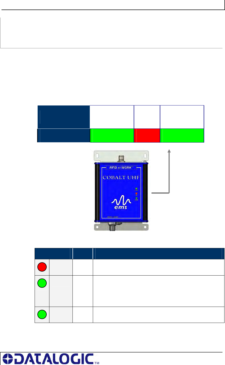
4.1.1 LED Behavior for Cobalt UHF-CNTL-232-02
Cobalt UHF-232 RFID Controller has three LED indicators conveniently located on
the front of the device, that convey visual information to the operator.
LED FUNCTION PWR
Power On
RF
Activity
COM
Activity
LED COLOR Green Red Green
LEDs Description
LED COLOR NAME LED DESCRIPTION
RED RF The RF LED illuminates when RF power is being transmitted by
the antenna.
GREEN COM The COM (communications) LED flashes ON and OFF when
data is being transmitted between the antenna and a tag.
When in Continuous Read mode, the COM LED will remain ON
and will turn OFF briefly only while data is being read from or
written to a tag.
GREEN PWR The PWR (power) LED is ON whenever power is applied to the
Cobalt.
Table 4-1: UHF-CNTL-232-02 - LEDs Description
COBALT UHF-SERIES CHAPTER 4: LED STATUS
PAGE 43 OF 140
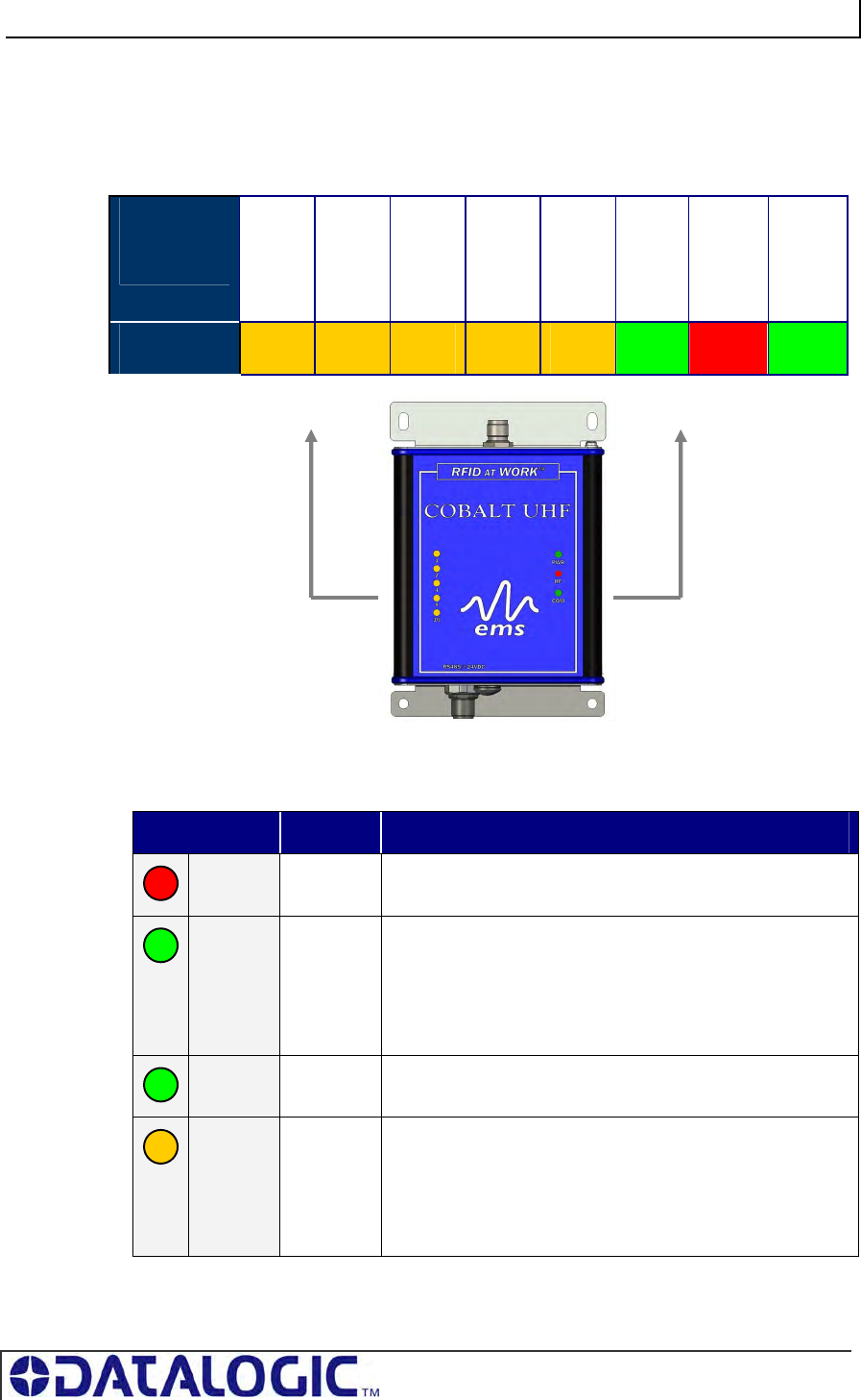
4.1.2 LED Behavior for Cobalt UHF-CNTL-485-02
The Cobalt UHF-485 RFID Controller has eight LED indicators conveniently located
on the front of the device, that convey visual information to the operator.
LED
FUNCTION
16
Node
(24)
8
Node
(23)
4
Node
(22 )
2
Node
(21)
1
Node
(20)
PWR
Power
On
RF
Activity
COM
Activity
LED COLOR Amber Amber Amber Amber Amber Green Red Green
LEDs Description
LED COLOR NAME LED DESCRIPTION
RED RF The RF LED illuminates when RF power is being transmitted
by the antenna.
GREEN COM The COM (communications) LED flashes ON and OFF
when data is being transmitted between the antenna and a
tag.
When in Continuous Read mode, the COM LED will remain
ON and will turn OFF briefly only while data is being read
from or written to a tag.
GREEN PWR The PWR (power) LED is ON whenever power is applied to
the Cobalt.
AMBER 16,8,4,2,1
(Node
LEDs)
The five amber Node LEDs on the right side indicate the
current Subnet 16 address of the unit. In binary from bottom
to top, they indicate the current Node ID value assigned to
the controller.
For example, Node 9 will have: Led 16 OFF, Led 8 ON, Led
2 OFF, Led 1 ON
Table 4-2: UHF-CNTL-485-02 - LEDs Description
COBALT UHF-SERIES CHAPTER 4: LED STATUS
PAGE 44 OF 140
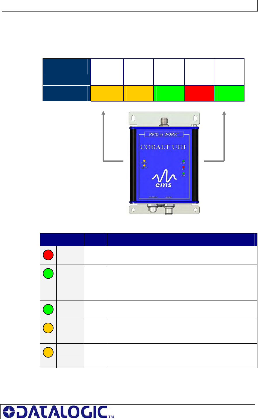
4.1.3 LED Behavior for Cobalt UHF-CNTL-IND-02
The Cobalt UHF-IND RFID Controller has five LED indicators conveniently located
on the front of the device, that convey visual information to the operator.
LED FUNCTION DEF IP
ACT IP
PWR
Power On
RF
Activity
COM
Activity
LED COLOR Amber Amber Green Red Green
LEDs Description
LED COLOR NAME LED DESCRIPTION
RED RF The RF LED illuminates when RF power is being transmitted by
the antenna.
GREEN COM The COM (communications) LED flashes ON and OFF when
data is being transmitted between the antenna and a tag.
When in Continuous Read mode, the COM LED will remain ON
and will turn OFF briefly only while data is being read from or
written to a tag.
GREEN PWR The PWR (power) LED is ON whenever power is applied to the
Cobalt.
AMBER DEF IP The DEF IP LED indicate the status of the IP address in the
unit. It illuminates when the IP address of the unit is the default
one: 192.168.253.110
AMBER ACT IP The ACT IP LED indicate the status of the IP address in the
unit. It illuminates when the IP address of the unit is not the
default one, but one chosen by the user.
Table 4-3: UHF-CNTL-IND-02 - LEDs Description
COBALT UHF-SERIES CHAPTER 5: COMMAND PROTOCOLS
PAGE 45 OF 140
CHAPTER 5:
COMMAND PROTOCOLS
5.1 COMMAND PROTOCOLS OVERVIEW
In order to execute RFID commands properly, the Cobalt UHF and host computer
must be able to communicate using the same language. The language that is used to
communicate is referred to as the Command Protocol.
When an RFID command is issued, the host computer instructs the RFID controller to
perform a given task. After performing that task, the RFID controller will normally
reply back with a Command Response message indicating the status or results of the
attempted command. This response notifies the host as to whether the command
was successfully completed or if the RFID controller failed to complete the command.
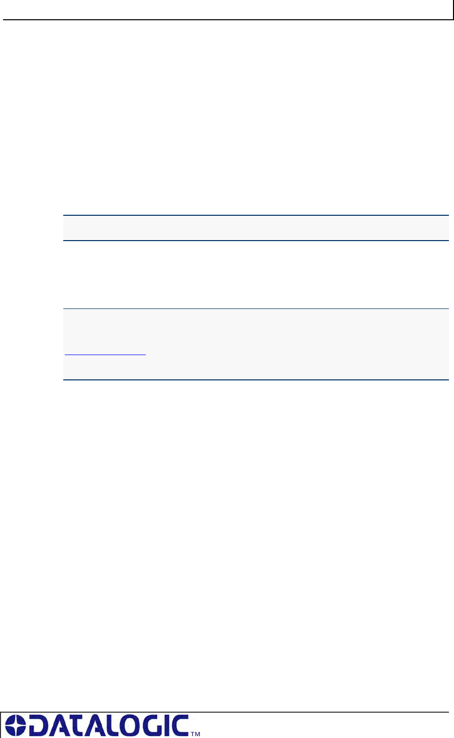
The Cobalt RFID product line by Datalogic supports three basic command protocols:
CBx, ABx Fast and ABx Standard. To determine which command protocol to utilize
for the different versions of Cobalt UHF Series, please refer to the table below:
PRODUCT CBX ABX FAST ABX STANDARD
UHF-CNTL-232-02 X X
UHF-CNTL-IND-02 X
UHF-CNTL-485-02 X
Table 5-1: Command Protocol Matrix
NOTE: RS485-based RFID controllers are used in conjunction with Subnet16 Gateway
and Subnet16 Hub interface modules, which use the CBx Command Protocol.
COBALT UHF-SERIES CHAPTER 5: COMMAND PROTOCOLS
PAGE 46 OF 140
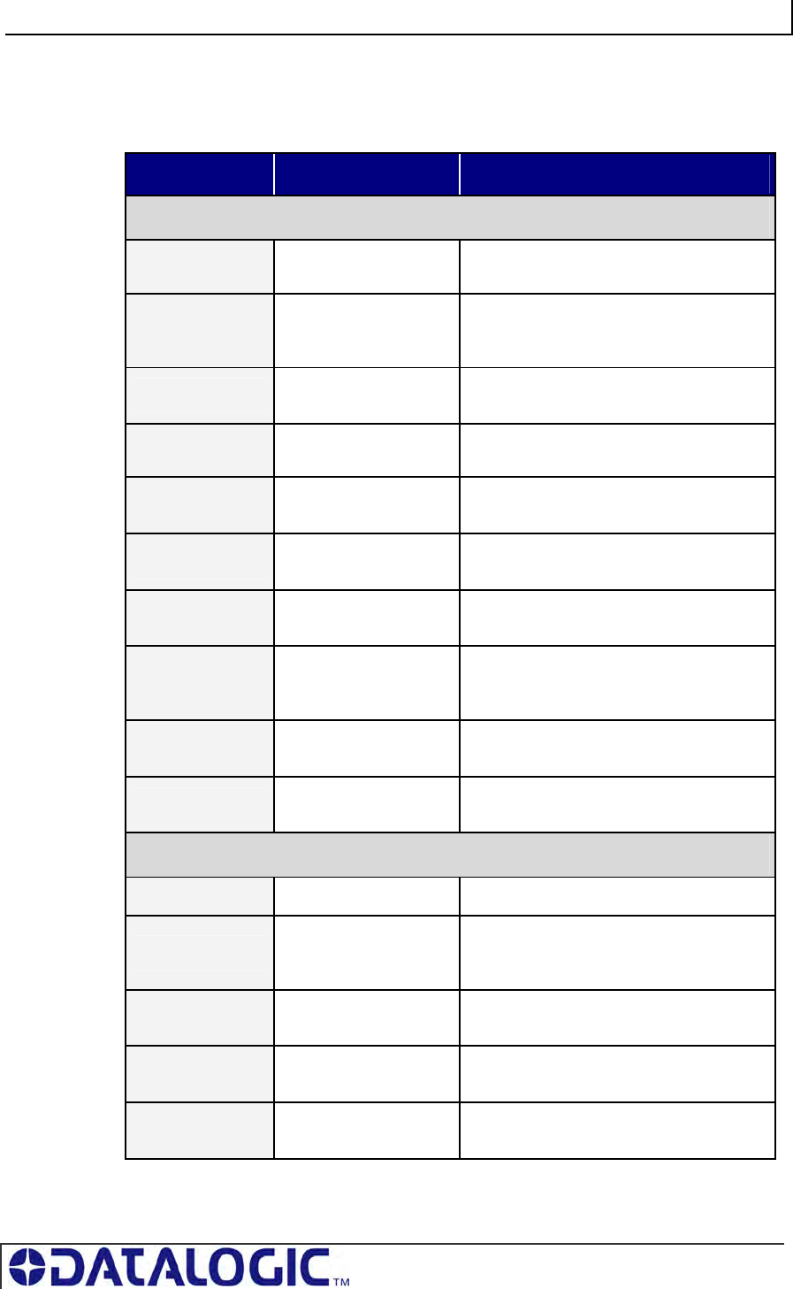
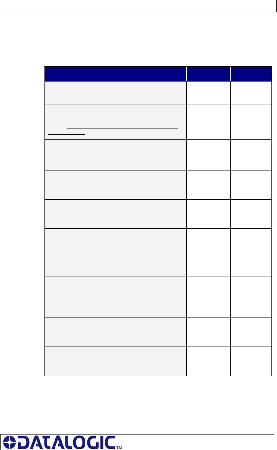
5.2 RFID COMMAND TABLE
This is a list of all the commands supported by the Cobalt UHF Series controllers:
COMMAND ID COMMAND NAME DESCRIPTION
Single-Tag RFID Commands
0x04 Fill Tag Fills a specified tag address range with a
one-byte value
0x05 Read Data
Reads a specified length of data from a
contiguous (sequential) area of tag
memory
0x06 Write Data Writes a specified number of bytes to a
contiguous area of tag memory
0x07 Read Tag ID Retrieves a tag’s unique identification (Tag
ID) number
0x08 Tag Search Instructs the controller to search for a tag
in its RF field
0x0D Start Continuous
Read Instructs the controller to start or stop
Continuous Read mode.
0x0E Read Tag ID and
Data Reads a tag’s ID number as well as a
specified number of bytes of tag memory
0x0F
Start Continuous
Read Tag ID and
Data
Instructs the controller to start or stop
Continuous Read Tag ID and Data mode.
0xC2 Read EPC Code Retrieves the tag’s Electronic Product
Code Identity
0xC3 Write EPC Code Used to modify the tag’s factory default
Electronic Product Code Identity
RFID Controller Commands
0x35 Reset Controller Resets power to the controller
0x36 Set Controller
Configuration
Used to set (configure or modify) the
controller’s configuration parameters and
settings
0x37 Get Controller
Configuration Retrieves the controller’s configuration
settings
0x38 Get Controller
Info Retrieves hardware, firmware and serial
number information from the controller
0x51 Set Controller
Time Used to set the time for the controller
COBALT UHF-SERIES CHAPTER 5: COMMAND PROTOCOLS
PAGE 47 OF 140
COMMAND ID COMMAND NAME DESCRIPTION
0x56 Set Controller
Trigger Used to set the parameters for one of the
controller’s eight triggers
0x57 Get Controller
Trigger Used to retrieve the parameters of one of
the controller’s eight triggers
0x70 Set Controller
Macro Used to set the parameters for one of the
controller’s eight macros
0x71 Get Controller
Macro Used to retrieve the parameters of one of
the controller’s eight macros
0x72 Execute
Controller Macro Instructs the controller to execute one of its
eight macros
0xC0 Set UHF
Configuration
Used to set (configure or modify) the
controller’s UHF configuration parameters
and settings
0xC1 Get UHF
Configuration Retrieves the controller’s UHF
configuration parameters
Multi-Tag RFID Commands
0x82 Multi-Tag Read
ID and Data All Retrieves a contiguous segment of data and
the tag ID from all RFID tags in range
0x85 Multi-Tag Block
Read All Retrieves a contiguous segment of data
from all RFID tags in range
0x87 Multi-Tag Get
Inventory Retrieves the tag ID from all RFID tags in
range
0xC4 Read EPC Code Retrieves the Electronic Product Code
Identities for all tags in range (multi-tag
inventory)
Table 5-2: RFID Command Table
COBALT UHF-SERIES CHAPTER 5: COMMAND PROTOCOLS
PAGE 48 OF 140
5.2.1 RFID Commands - Note About the UHF-G2-525xx Tag
Memory Structure
The memory in Datalogic’s EPC Class 1 Gen 2 tag UHF-G2-525xx is organized in three
areas:
NAME DESCRIPTION SIZE
EPC EPC memory according to
the EPCglobal standard
96 bit ( 12 bytes )
TID Read Only Unique identifier 64 bits ( 8 bytes )
USER User memory 512 bit ( 64 bytes )
Table 5-3: UHF-G2-525xxx Tag Memory Structure
EPC
EPC is a numbering scheme that allows assignment of a unique identifier to any
physical object. It can be regarded as the next generation of Universal Product Code
(UPC), which is used on most products today.
EPC enables the means to assign a unique identifier to each item, thus allowing
every item to be uniquely identified.
To have more details on the structure of the EPC memory area please consult:
EPC Radio-Frequency Identity Protocols Class-1 Generation-2 UHF RFID Protocol
for Communications at 860 Mhz – 960 Mhz, Version 1.1.0 (December 17, 2005)
In our UHF-G2-525xx tag this memory area is preprogrammed with the TID unique
identifier and padded with zeroes. The user can change that but it’s important to note
that only tags with different EPC codes will be discriminated in a multitag reading
environment.
TID
This is a read-only area that holds a unique tag identifier number. This area can be
accessed using the common ABx/CBx Read ID commands.
USER
This is the normal data area that can be accessed using the common ABx/CBx
Read and Write commands.
NOTE: The fastest access memory is the EPC area. For applications where speed is
important the use of this memory is recommended.
COBALT UHF-SERIES CHAPTER 5: COMMAND PROTOCOLS
PAGE 49 OF 140
5.3 ABX COMMAND PROTOCOL OVERVIEW
There are two versions of the ABx Command Protocol that are supported by the
Cobalt UHF Serial Controller, they are:
ABx Fast (default)
ABx Standard
The ABx Fast Command Protocol has a single-byte based packet structure that
permits the execution of RFID commands while requiring the transfer of fewer total
bytes than ABx Standard. ABx Fast is the default command protocol used by Cobalt
UHF Serial RFID Controller. It can be used with or without a checksum byte.
The ABx Standard Command Protocol uses a double-byte, word based format that
shares a common syntax with most existing RFID systems produced by Escort
Memory Systems. This protocol offers legacy support, which may be required by
existing PLC applications that only support a 2-byte word packet format. If your
application requires compatibility with existing or legacy RFID devices from
Datalogic’s EMS product line, use ABx Standard. ABx Standard does not support the
use of a checksum byte.
NOTE:
By default, the UHF-CNTL-232-02 is configured to use the ABx Fast Command
Protocol. ABx Fast (as the name suggests) is the faster and more efficient of the two
ABx protocols, offering increased communication speed and error immunity.
5.3.1 ABx Command Packet Structure
All ABx-based RFID commands contain certain fundamental packet elements,
including a Command Header, a Command ID, one or more Command
Parameters (when applicable) and a Command Terminator.
Command Packet Structure = [Command Header + Command ID + Command
Parameters + Command Terminator]
5.3.2 ABx Protocols - Headers and Terminators
In ABx Standard, commands begin with the one-byte command header "0xAA," and
end with the two-byte command terminator "0xFF, 0xFF".
In ABx Fast, commands begin with the two-byte command header “0x02, 0x02” and
end with the one-byte command terminator “0x03.”
See the table below for further clarification.
ABx Protocols - Headers and Terminators
ABX PROTOCOL HEADER TERMINATOR
ABx Fast 0x02, 0x02 0x03
ABx Standard 0xAA 0xFF, 0xFF
Table 5-4: ABx Protocols - Headers and Terminators
COBALT UHF-SERIES CHAPTER 5: COMMAND PROTOCOLS
PAGE 50 OF 140
When a command is issued by the host, the RFID controller stores the incoming data
packet in a buffer while it scans the data for a start character (0x02, 0x02 or 0xAA).
When a start character is found, it checks for the proper terminator (0x03 or 0xFF,
0xFF). Having identified a potentially valid command string, the controller will verify
the format of the data and either perform the requested function or generate an error
message.
5.3.3 ABx Response Packet Structure
After completing an ABx command, the RFID controller generates a host-bound,
response packet that indicates the status and/or results of the attempted command.
The response packet structure for all ABx protocols consists of a Response Header,
a Command Echo, one or more Response Values (when applicable), and a
Response Terminator.
Response Packet Structure = [Response Header + Command Echo + Response
Values + Response Terminator]
Note that, for each ABx protocol, response header and response terminator
parameters are the same as their command header and command terminator
counterparts.
ATTENTION: This Cobalt UHF Series Manual does NOT contain descriptions or
examples of each supported RFID command common to all the devices in the Cobalt
family. For complete details regarding the use of common RFID commands please visit
www.ems-rfid.com and download the ABx Standard Command Protocol – Reference
Manual or the ABx Fast Command Protocol – Reference Manual. Here you will find
only the commands that are specific to the UHF controller.
COBALT UHF-SERIES CHAPTER 5: COMMAND PROTOCOLS
PAGE 51 OF 140
5.4 ABX FAST COMMAND PROTOCOL
The default command protocol used by UHF-CNTL-232-02 RFID Controllers for
Point-to-Point data transmission is known as the ABx Fast Command Protocol.
ABx Fast has a single-byte oriented packet structure that permits the rapid execution
of RFID commands while requiring the transfer of a minimal number of bytes.
ABx Fast supports the inclusion of an optional checksum byte. When increased data
integrity is required, the checksum should be utilized. See Section 5.4.3 “Command
Packet Elements” for more on using the checksum parameter.
5.4.1 ABx Fast - Command / Response Procedure
After an RFID command is issued by the host, a packet of data, called the
“Command Packet” is sent to the controller. The command packet contains
information that instructs the controller to perform a certain task.
The controller automatically parses the incoming data packet, searching for a specific
pair of start characters, known as the “Command Header.” In ABx Fast, the
Command Header / Start Characters are 0x02, 0x02. When a valid Command
Header is recognized, the controller then checks for proper formatting and for the
presence of a Command Terminator byte. In ABx Fast, the Command Terminator
byte is 0x03.
Having identified a valid command, the controller will attempt to execute the given
instructions. After which the controller will generate a host-bound response message
containing EITHER the results of the attempted command or an error code if the
operation failed.
Note that all commands generate a response from the controller. Before sending a
second or additional command to a controller, allow the host to first process (remove
from memory) any pending response data.
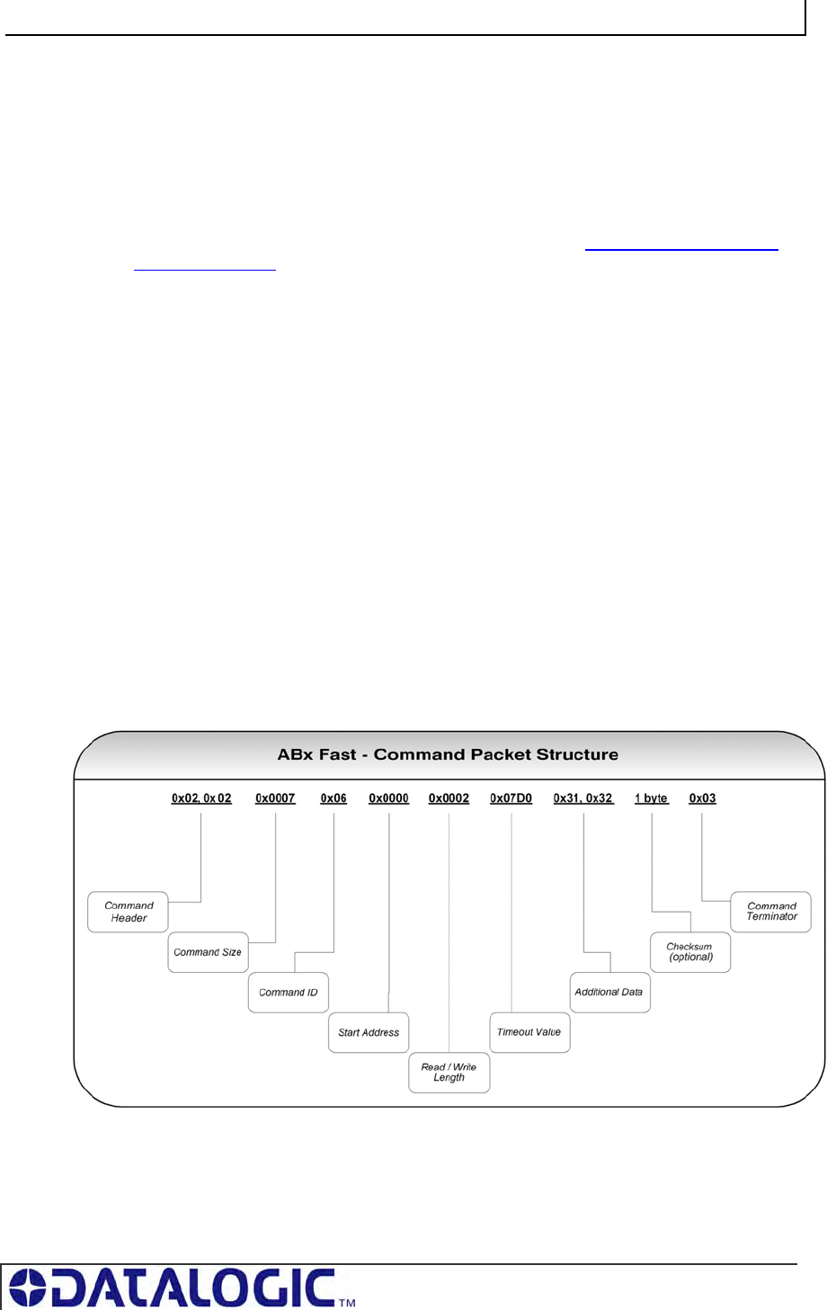
Table 5-5: ABx Fast - Command Packet Structure
COBALT UHF-SERIES CHAPTER 5: COMMAND PROTOCOLS
PAGE 52 OF 140
5.4.2 ABx Fast - Command Packet Structure
The packet structure of all ABx Fast RFID commands contains certain basic
elements, including Command Header, Command Size, Command ID and
Command Terminator. Packet element and parameter availability depends on the
command being performed.
COMMAND PACKET ELEMENT CONTENT SIZE
COMMAND HEADER:
The first two bytes of an ABx Fast command.
0x02, 0x02 2 bytes
COMMAND SIZE:
This two-byte integer defines the number of bytes in the
packet (excluding Header, Command Size, Checksum
and Terminator).
0x0007 +
(number of
bytes of
additional data)
2-byte integer
COMMAND ID:
This single-byte value indicates the RFID command to
execute.
0x06
(Write Data)
1 byte
START ADDRESS:
This two-byte integer indicates the location of tag
memory where a read or write operation shall begin.
0x0000 2-byte integer
BLOCK SIZE:
This two-byte integer represents the number of bytes
that are to be read from or written to the RFID tag.
0x0001 2-byte integer
TIMEOUT VALUE:
This two-byte integer indicates the maximum length of
time for which the controller will attempt to complete the
command. Measured in milliseconds, this value can
have a range of 0x0001 to 0xFFFE or between 1 and
65,534 msecs.
0x07D0
(0x07D0 =
2000 x .001 =
2 seconds)
2-byte integer
ADDITIONAL DATA:
This parameter uses one byte to hold a single character
for fill operations and supports the use of multiple bytes
when several characters are needed for write
commands (when applicable).
0x00 1 or more
bytes
CHECKSUM:
This optional parameter holds a single-byte checksum
(only applicable when using ABx Fast with Checksum).
Optional 1 byte (when
applicable)
COMMAND TERMINATOR:
The single-byte command packet terminator is always
0x03 for ABx Fast.
0x03 1 byte
Table 5-6: ABx Fast - Command Packet Structure
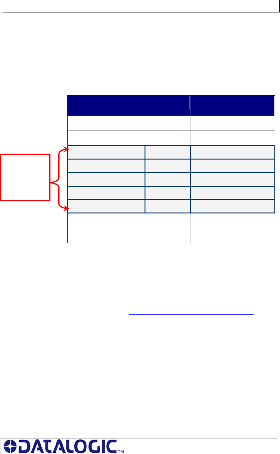
COBALT UHF-SERIES CHAPTER 5: COMMAND PROTOCOLS
PAGE 53 OF 140
5.4.3 ABx Fast – Command Packet Elements
Command Size
The ABx Fast protocol requires that the byte count, known as the Command Size,
be specified as a two-byte integer within each command packet. To calculate the
Command Size, add the total number of bytes within the command packet while
excluding the two byte Command Header, the two byte Command Size, the one byte
Checksum (if present) and the one byte Command Terminator (see example below).
COMMAND PACKET
ELEMENT
# OF BYTES INCLUDED IN COMMAND
SIZE?
Command Header 2 No
Command Size 2 No
Command ID 1 Yes
Start Address 2 Yes
Read/Block Size 2 Yes
Timeout Value 2 Yes
Additional Data Bytes 1 Yes (if present)
Checksum 1 No
Command Terminator 1 No
Table 5-7: ABx Fast - Command Size Parameter
In the above sample command packet, there are eight bytes of data (located
between the Command Size parameter and the Checksum parameter) that are
included in the Command Size. Therefore, the Command Size for this example is
0x0008.
Command ID
The one-byte Command ID parameter identifies the Hex value of the RFID
command to perform. (See the Section 5.2 - ABx Fast RFID Command Table.)
Start Address
The Start Address parameter holds a two-byte integer representing the tag memory
address location where a read or write operation is to begin.
Block Size (Read/Write Length)
The two-byte Block Size parameter (which is also sometimes called the Read /
Write Length parameter) indicates the number of bytes that are to be read from or
written to the RFID tag.
Command
Size =
number of
bytes in these
fields
COBALT UHF-SERIES CHAPTER 5: COMMAND PROTOCOLS
PAGE 54 OF 140
Timeout Value
Most ABx Fast commands include a two-byte Timeout Value, which is used to limit
the length of time that the Cobalt UHF will attempt to complete the specified
operation.
The Timeout Value is measured in 1-millisecond increments and has a maximum
supported value of 0xFFFE or 65,534 milliseconds (which is slightly longer than one
minute).
Setting a long Timeout Value does not necessarily mean that a command will take
any longer to execute. This value only represents the period of time for which the
Cobalt UHF will attempt execution of the command.
IMPORTANT:
During write commands, the tag must remain within the antenna’s RF field until the
write operation completes successfully, or until the Timeout Value has expired.
If a write operation is not completed before the tag leaves the controller’s RF field, data
may be incompletely written.
Checksum
The ABx Fast Command Protocol supports the inclusion of an optional Checksum
byte that is used to verify the integrity of data being transmitted between host and
controller.
The Checksum is calculated by adding together (summing) the byte values in the
command packet (less the Command Header, Checksum and Command Terminator
parameters), and then subtracting the total byte sum from 0xFF.
Therefore, when the byte values of each parameter (from Command Size to
Checksum) are added together, the byte value sum will equal 0xFF.
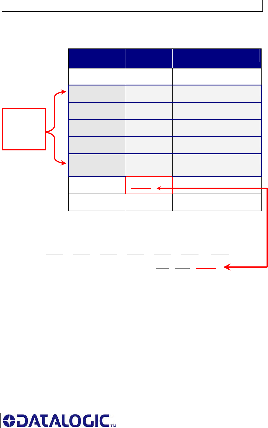
COBALT UHF-SERIES CHAPTER 5: COMMAND PROTOCOLS
PAGE 55 OF 140
CHECKSUM EXAMPLE
The following example depicts Command 0x05 (Read Data) when using a
Checksum.
COMMAND
ELEMENT
CONTENTS USED IN CHECKSUM
Header 0x02, 0x02 n/a
Command Size 0x0007 0x00, 0x07
Command ID 0x05 0x05
Start Address 0x0001 0x00, 0x01
Block Size 0x0004 0x00, 0x04
Timeout Value 0x07D0 0x07, 0xD0
Checksum 0x17 n/a
Terminator 0x03 n/a
Table 5-8: ABx Fast - Checksum Example
Add the byte values from the Command Size, Command ID, Start Address, Block
Size and Timeout Value parameters together and subtract from 0xFF. The resulting
value will be the Checksum.
[0x07 + 0x05 + 0x01 + 0x04 + 0x07 + 0xD0] = 0xE8
The checksum equation is: [0xFF – 0xE8] = 0x17
Checksum
= [0xFF –
(sum of
these fields)]
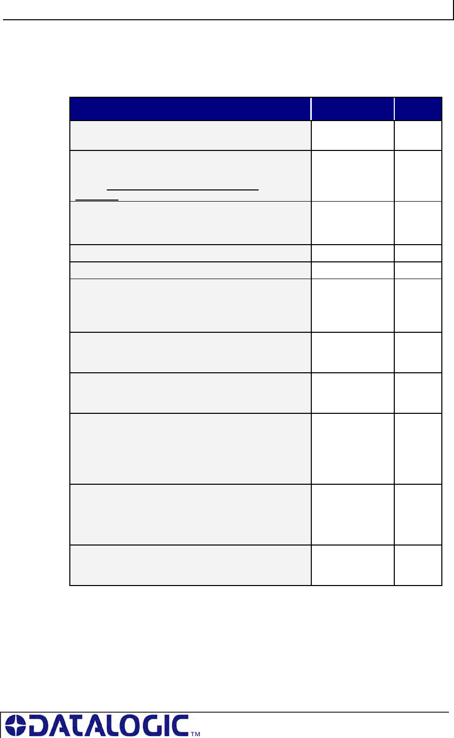
COBALT UHF-SERIES CHAPTER 5: COMMAND PROTOCOLS
PAGE 56 OF 140
5.4.4 ABx Fast - Multi-Tag Command Packet Structure
Multi-tag (anti-collision) commands are used to communicate with one or more RFID
tags, when numerous tags are simultaneously within RF range. ABx Fast Multi-tag
commands are formatted as follows:
COMMAND PACKET ELEMENT CONTENT SIZE
COMMAND HEADER:
The first two bytes of an ABx Fast command.
0x02, 0x02 2 bytes
COMMAND SIZE:
This two-byte integer defines the number of bytes in the
packet (excluding Header, Command Size and
Terminator).
0x0007 +
(number of bytes
of additional
data)
2-byte
integer
COMMAND ID:
This single-byte value indicates the RFID command to
execute.
0x06
(Write Data)
1 byte
Reserved for future use 0x00 1 byte
Reserved for future use 0x00 1 byte
TAG LIMIT:
This single byte specifies the maximum # of tags
expected in RF range, up to 100; 0x64 = 100 tags
expected max (when applicable)
0x64 1 byte
START ADDRESS:
This two-byte integer indicates the location of tag
memory where a read or write operation shall begin.
0x0000 2-byte
integer
BLOCK SIZE (READ/WRITE LENGTH):
This two-byte integer represents the number of bytes that
are to be read from or written to the RFID tag.
0x0001 2-byte
integer
TIMEOUT VALUE:
This two-byte integer indicates the maximum length of
time for which the controller will attempt to complete the
command. Measured in milliseconds, this value can have
a range of 0x0001 to 0xFFFE or between 1 and 65,534
msecs.
0x07D0
(0x07D0 = 2000
x .001 = 2
seconds)
2-byte
integer
ADDITIONAL DATA:
This parameter uses one byte to hold a single character
for fill operations and supports the use of multiple bytes
when several characters are needed for write commands
(when applicable).
0x00 1 or
more
bytes
COMMAND TERMINATOR:
The single-byte command packet terminator is always
0x03 for ABx Fast.
0x03 1 byte
Table 5-9: ABx Fast - Anti-Collision Command Packet Structure

COBALT UHF-SERIES CHAPTER 5: COMMAND PROTOCOLS
PAGE 57 OF 140
5.4.5 ABx Fast - Multi-Tag Command Packet Elements
Tag Limit
The Tag Limit parameter holds a one-byte value that indicates the maximum number
of tags expected simultaneously in RF range for the given command operation.
This parameter allows users to limit the number of attempted read/write operations
the controller will make per execution. Users do not have to wait for the timeout to
expire.
The Tag Limit value should be set in relation to the maximum number of tags that
could possibly be present in the reading field at any one time. Setting the value
higher increases the number of tags expected to be read in the antenna’s RF field.
Lowering the value, however, can speed up tag read operations for a small group of
tags. Setting the proper value is therefore a tradeoff between the number of
expected tags in the reading field, and the time required to read/write to them. The
permitted values range from zero to 100 (0x00 – 0x64). The Tag Limit parameter
resides directly after the “Anti-collision Mode” parameter in the command string
(when applicable).
Timeout Value
Multi-tag commands also contain a two-byte Timeout Value parameter that is used to
limit the length of time for which the Cobalt will attempt to complete a given operation.
It is important to set a realistic Timeout Value that permits enough time for the Cobalt
to read/write to all tags specified in the command. Processing multiple-tag operations
requires a longer time period than does the execution of single-tag commands.
The value is expressed in one-millisecond increments, with a maximum value of
0xFFFE (65,534 milliseconds) or approximately 60 seconds. For most single tag
read/write commands, a Timeout Value of at least 1000ms is recommended.
However, it is recommended that you allow an additional 100ms per tag for multi-tag
read operations and 150ms per tag for multi-tag writes.
Timeout Value Example
When writing to 16 different tags in RF range, for example, set the two-byte Timeout
Value to at least 0x0D48 (16 x 150ms + 1000ms = 3400ms or 3.4 seconds). A
Timeout Value of zero (0x0000) will cause the Cobalt to return a syntax error
message.
Using a Timeout Value that is too short may result in diminished read/write range.
Setting a long Timeout Value does not necessarily mean that the command will take
any longer to complete. The value only represents the period of time in which the
Cobalt will attempt to complete the particular operation. If all required tags are in RF
range when the command is sent, the time necessary to complete the command will
be approximately the same whether the Timeout Value is 1000ms or 10,000ms.
For time critical applications, the optimal Timeout Value should be obtained through
rigorous performance testing.
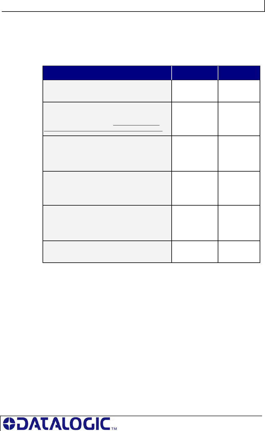
COBALT UHF-SERIES CHAPTER 5: COMMAND PROTOCOLS
PAGE 58 OF 140
5.4.6 ABx Fast - Response Packet Structure
After performing a command, the Cobalt UHF will generate a host-bound response
packet. ABx Fast responses contain a Response Header, Response Size,
Command Echo, one or more Response Values / Retrieved Data (when
applicable), and a Response Terminator.
RESPONSE PACKET ELEMENT CONTENT SIZE
RESPONSE HEADER:
The first two bytes of an ABx Fast response packet
0x02, 0x02 2 bytes
RESPONSE SIZE:
This two-byte integer indicates the total number of
bytes in the response packet (excluding Response
Header, Response Size, Checksum and Terminator).
0x0001 +
(number of bytes
of retrieved data)
2-byte integer
COMMAND ECHO:
This single-byte parameter reiterates the Hex value of
the command for which the response packet was
generated.
0x06 1 byte
RESPONSE VALUES / RETRIEVED DATA:
This parameter is used to hold one or more bytes of
the data that was requested by the command (when
applicable).
Data 1 or more bytes
(when
applicable)
CHECKSUM:
This optional parameter holds a single-byte checksum
(only applicable when using ABx Fast with
Checksum).
Optional 1 byte
(when
applicable)
RESPONSE TERMINATOR:
Single-byte response packet terminator (always 0x03)
0x03 1 byte
Table 5-10: ABx Fast - Response Packet Structure
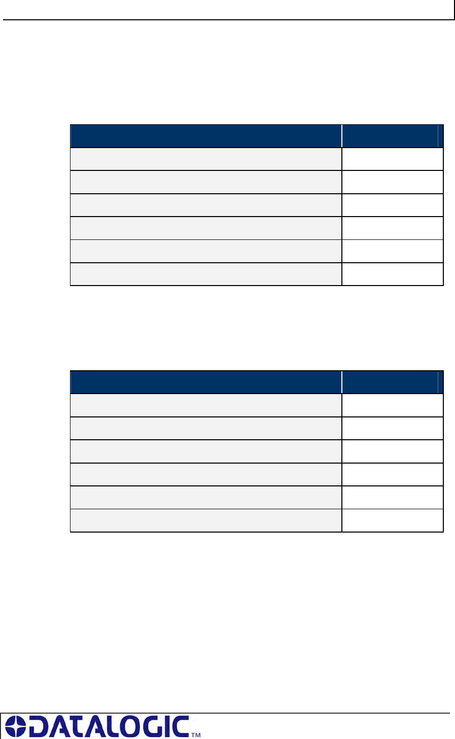
COBALT UHF-SERIES CHAPTER 5: COMMAND PROTOCOLS
PAGE 59 OF 140
5.4.7 ABx Fast Protocol:
Error Response Packet Structure
ABx Fast error responses contain a two-byte Response Header, a two-byte
Response Size parameter followed by a single-byte Error Flag (0xFF), a single-byte
Error Code, which identifies the error that occurred, and a single-byte Response
Terminator.
ERROR RESPONSE ELEMENT CONTENT
Response Header 0x02, 0x02
Response Size 0x0002
Error Flag 0xFF
Error Code <1-byte error code>
Checksum Optional
Response Terminator 0x03
Table 5-11: ABx Fast - Error Response Structure
ABX FAST - ERROR RESPONSE EXAMPLE
Below is an example of an ABx Fast error response for a failed Write Data operation
(Error Code 0x06).
ERROR RESPONSE ELEMENT CONTENT
Response Header 0x02, 0x02
Response Size 0x0002
Error Flag 0xFF
Error Code 0x06
Checksum Optional
Response Terminator 0x03
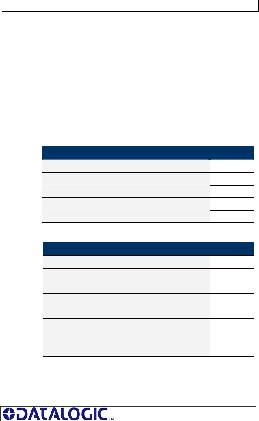
COBALT UHF-SERIES CHAPTER 5: COMMAND PROTOCOLS
PAGE 60 OF 140
COMMAND 0XC2 – DESCRIPTION
The Read EPC Command instructs the controller to retrieve the EPC memory area
of a single tag UHF Class1 Gen2.
COMMAND 0XC2 - ABX FAST EXAMPLE
This example instructs the controller to read the EPC memory from a tag. A Timeout
Value of 2 seconds (0x07D0 = 2000 x one-millisecond increments) is set for the
completion of the command.
Command from Host
PARAMETER FIELD CONTENT
Header 0x02, 0x02
Command Size 0x0003
Command ID 0xC2
Timeout Value 0x07D0
Terminator 0x03
Response from Controller
PARAMETER FIELD CONTENT
Header 0x02, 0x02
Response Size 0x000D
Command Echo 0xC2
EPC byte 1 0x05
EPC byte 2 0xAA
EPC bytes 3… to 11 ……..
EPC byte 12 0x07
Terminator 0x03
SINGLE-TAG RFID COMMAND 0XC2:
READ EPC CODE
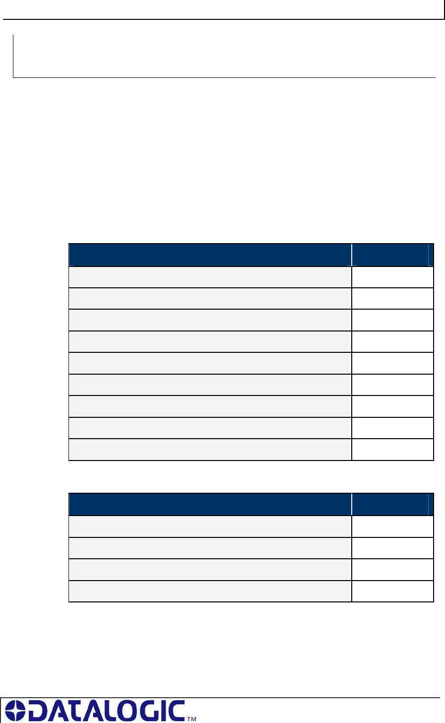
COBALT UHF-SERIES CHAPTER 5: COMMAND PROTOCOLS
PAGE 61 OF 140
COMMAND 0XC3 – DESCRIPTION
The Write EPC Command instructs the controller to write the EPC memory area of a
single tag UHF Class1 Gen2.
COMMAND 0XC3 - ABX FAST EXAMPLE
This example instructs the controller to write the specified bytes in the EPC memory
of a tag. A Timeout Value of 2 seconds (0x07D0 = 2000 x one-millisecond
increments) is set for the completion of the command.
Command from Host
PARAMETER FIELD CONTENT
Header 0x02, 0x02
Command Size 0x000F
Command ID 0xC3
EPC Data Byte Value 1 0x48
EPC Data Byte Value 2 0x45
EPC Data Byte Value 3… to 11 …….
EPC Data Byte Value 12 0x4C
Timeout Value 0x07D0
Terminator 0x03
Response from Controller
PARAMETER FIELD CONTENT
Header 0x02, 0x02
Response Size 0x0001
Command Echo 0xC3
Terminator 0x03
SINGLE-TAG RFID COMMAND 0XC3:
WRITE EPC CODE
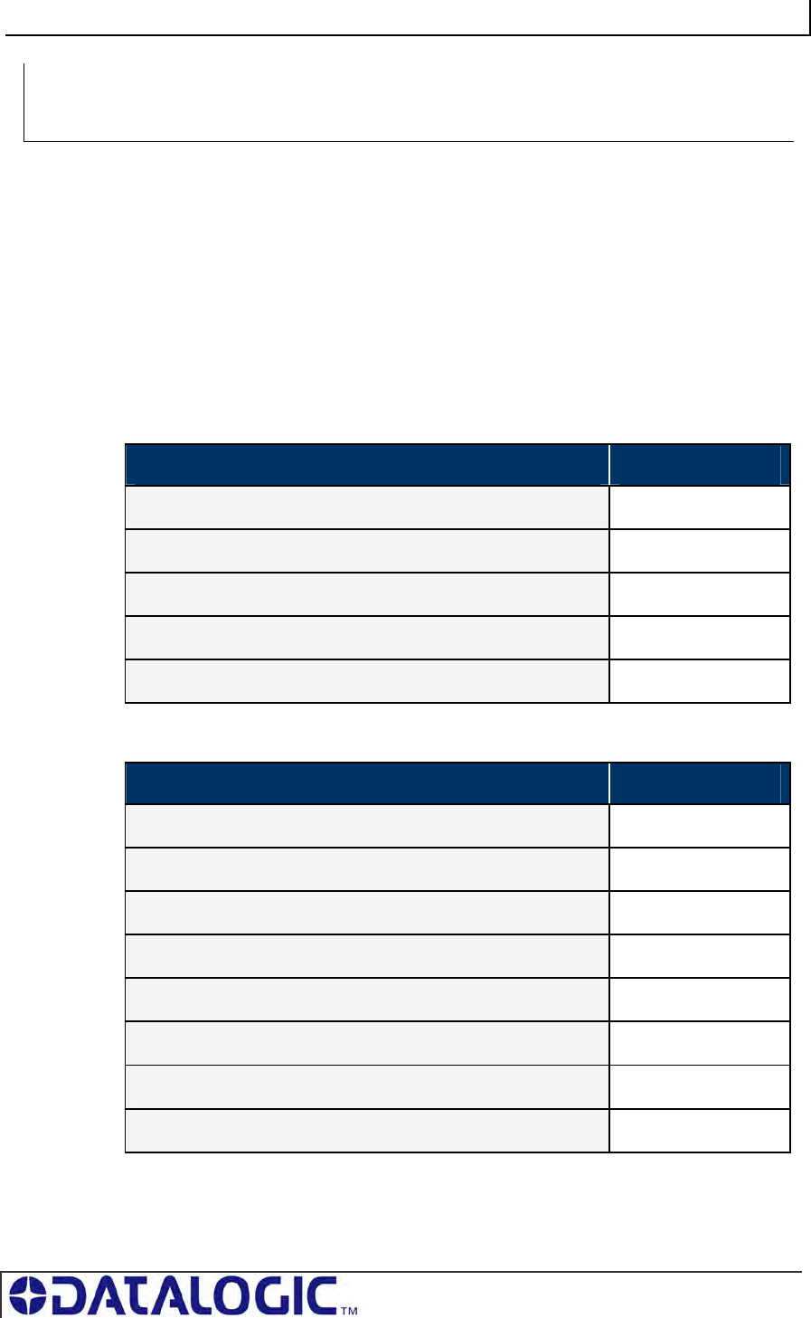
COBALT UHF-SERIES CHAPTER 5: COMMAND PROTOCOLS
PAGE 62 OF 140
COMMAND 0XC4 – DESCRIPTION
The Multi-Tag Read EPC Code is used to retrieve the EPC data from all tags within
RF range. A final termination packet is sent when the Timeout Value expires.
COMMAND 0XC4 - ABX FAST EXAMPLE
This example instructs the controller to read the EPC data from each tag in range. A
Timeout Value of 3 seconds (0x0BB8 = 3000 x 1msec increments) is set for the
completion of the command.
Command from Host
PARAMETER FIELD CONTENT
Command Header 0x02, 0x02
Command Size 0x0003
Command ID 0xC4
Timeout Value 0x0B, 0xB8
Command Terminator 0x03
Response for Each Tag Read
PARAMETER FIELD CONTENT
Response Header 0x02, 0x02
Response Size 0x000D
Command Echo 0xC4
EPC Read Data Byte 1 <D01>
EPC Read Data Byte 2 <D02>
. . . . . .
EPC Read Data Byte 12 <D12>
Response Terminator 0x03
MULTI-TAG RFID COMMAND 0XC4:
READ EPC CODE
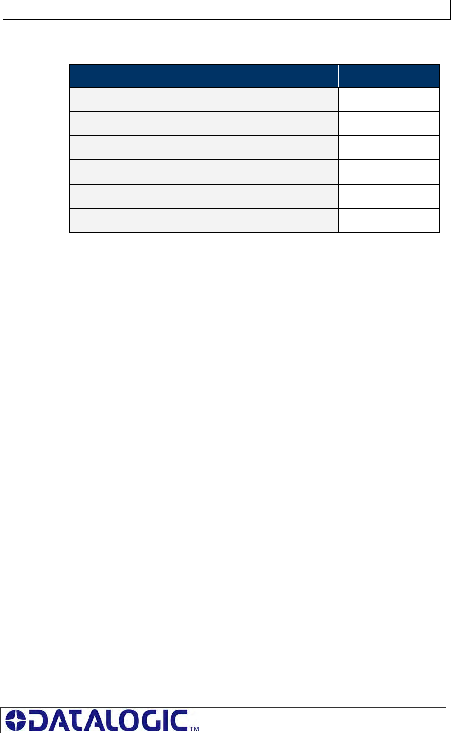
COBALT UHF-SERIES CHAPTER 5: COMMAND PROTOCOLS
PAGE 63 OF 140
Final Termination Packet
PARAMETER FIELD CONTENT
Response Header 0x02, 0x02
Response Size 0x0004
Final Termination Packet Identifier 0xFF
Number of Tags Read <N-tags>
Status 0x0000
Response Terminator 0x03
COBALT UHF-SERIES CHAPTER 5: COMMAND PROTOCOLS
PAGE 64 OF 140
COMMAND 0XC0 – DESCRIPTION
The Set UHF Configuration command is used to set (configure or modify) the
controller’s UHF configuration parameters and settings to the controller’s flash
memory.
IMPORTANT: it is recommended that users first run Command 0xC1: Get UHF
Configuration and make note of their current controller configuration values prior to
executing this command.
COMMAND 0XC0 - ABX FAST EXAMPLE
This example permits the user to modify or write the indicated configuration settings
to the controller’s flash memory. The total number of bytes available for this purpose
is nine.
Command from Host
PARAMETER FIELD CONTENT
Command Header 0x02, 0x02
Command Size 0x000A
Command ID 0xC0
UHF Configuration Bytes 1 & 2
This two-byte integer represents the
Reader Output Power ( value from 0
to 500 mW).
<2-bytes integer>
UHF Configuration Byte 3…to 7 <Reserved> *
UHF Configuration Byte 8
This byte permits the user to select
the specific UHF channel through
which commands are transmitted. The
user can write a value between o and
9 in bits from 4 to 7.
<Partially Reserved>
BIT Description
0 Reserved*
1 Reserved*
2 Reserved*
3 Reserved*
4 <Channel ID value>
5 <Channel ID value>
CONTROLLER SPECIFIC COMMAND 0XC0:
SET UHF CONFIGURATION
COBALT UHF-SERIES CHAPTER 5: COMMAND PROTOCOLS
PAGE 65 OF 140
6 <Channel ID value>
7 <Channel ID value>
UHF Configuration Byte 9
This byte permits the user to
enable/disable the Choose Nearest
One property.
If the Choose Nearest One property is
disabled, an error response is
generated whenever a single-tag
read/write command is executed in a
multi-tag environment.
If the Choose Nearest One property is
enabled, the read/write command is
executed on the tag with the stronger
signal.
<Partially Reserved>
BIT Description
0 Reserved*
1 <Choose Nearest One option>
2 Reserved*
3 Reserved*
4 Reserved*
5 Reserved*
6 Reserved*
7 Reserved*
Command Terminator 0x03
*Leave the default value retrieved through Command 0xC1: Get UHF Configuration
Response from Controller
PARAMETER FIELD CONTENT
Header 0x02, 0x02
Response Size 0x0001
Command Echo 0xC0
Terminator 0x03
COBALT UHF-SERIES CHAPTER 5: COMMAND PROTOCOLS
PAGE 66 OF 140
COMMAND 0XC1 – DESCRIPTION
The Get UHF Configuration Command instructs the controller to retrieve the
controller’s UHF configuration parameters and settings stored in the unit’s flash
memory. These are the same values that are set with Command 0xC0: Set UHF
Configuration.
COMMAND 0XC1 - ABX FAST EXAMPLE
Through this command, the user queries a Cobalt UHF RFID controller and reads the
controller’s UHF configuration data from its flash memory.
Command from Host
PARAMETER FIELD CONTENT
Header 0x02, 0x02
Command Size 0x0001
Command ID 0xC1
Terminator 0x03
Response from Controller
PARAMETER FIELD CONTENT
Header 0x02, 0x02
Response Size 0x000B
Command Echo 0xC1
UHF Bytes 1 & 2
This two-byte integer represents the Reader Output Power (0÷500
mW).
<2-bytes value>
UHF Byte 3 <1-byte value>
EPC bytes 4… to 8 ……..
EPC byte 9 <1-byte value>
Terminator 0x03
CONTROLLER SPECIFIC COMMAND 0XC1:
GET UHF CONFIGURATION
COBALT UHF-SERIES CHAPTER 5: COMMAND PROTOCOLS
PAGE 67 OF 140
5.5 CBX COMMAND PROTOCOL
The CBx Command Protocol is based on a double-byte oriented packet structure
where commands always contain a minimum of six data “words,” even when one or
more parameters are not applicable to the command. CBx does not support the
inclusion of a checksum byte.
The CBx Command Protocol, utilized by Cobalt UHF-CNTL-IND-02 and (when
connected to a Gateway or Hub interface module) UHF-CNTL-485-02 models,
includes Multidrop Subnet16™ networking support for use with Industrial Ethernet
applications.
Moreover, the packet structures described herein are protocol independent and can
be implemented the same for all Ethernet protocols (Ethernet/IP, Modbus TCP and
Standard TCP/IP protocol).
5.5.1 CBx - Command Procedure
Cobalt UHF-CNTL-485-02 Command Procedure
For the Cobalt UHF-CNTL-485-02, controller-bound commands are initiated by a host
computer or Programmable Logic Controller (PLC) and are delivered to the controller
by a Subnet16 Gateway or Subnet16 Hub Interface Module that is connected to the
host or PLC by standard Ethernet cabling.
Each Cobalt UHF-CNTL-485-02 connected to a Multi-drop Subnet16 network is
assigned an individual Node ID number between 1 and 16.
When a controller-bound command is issued, the instructions are retrieved by the
interface module (Gateway or Hub) and distributed to the correct RFID controller by
specifying the “Node ID” number of the particular controller.
Cobalt UHF-CNTL-IND-02 Command Procedure
For the Cobalt UHF-CNTL-IND-02, commands are initiated by a host computer or
Programmable Logic Controller (PLC) and are retrieved by the controller via Ethernet
connection.
Commands are directed to the Cobalt by specifying, in the command packet, the
“Node ID” number of the Cobalt Controller. For the Cobalt UHF-CNTL-IND-02, the
Node ID will always be 01 (0x01).
ATTENTION: This Cobalt UHF Series Manual does NOT contain descriptions or
examples of each supported RFID command common to all the devices in the Cobalt
family. For complete details regarding the use of common RFID commands please visit
www.ems-rfid.com and download the CBx Command Protocol – Reference Manual.
Here you will find only the commands that are specific to the UHF controller.
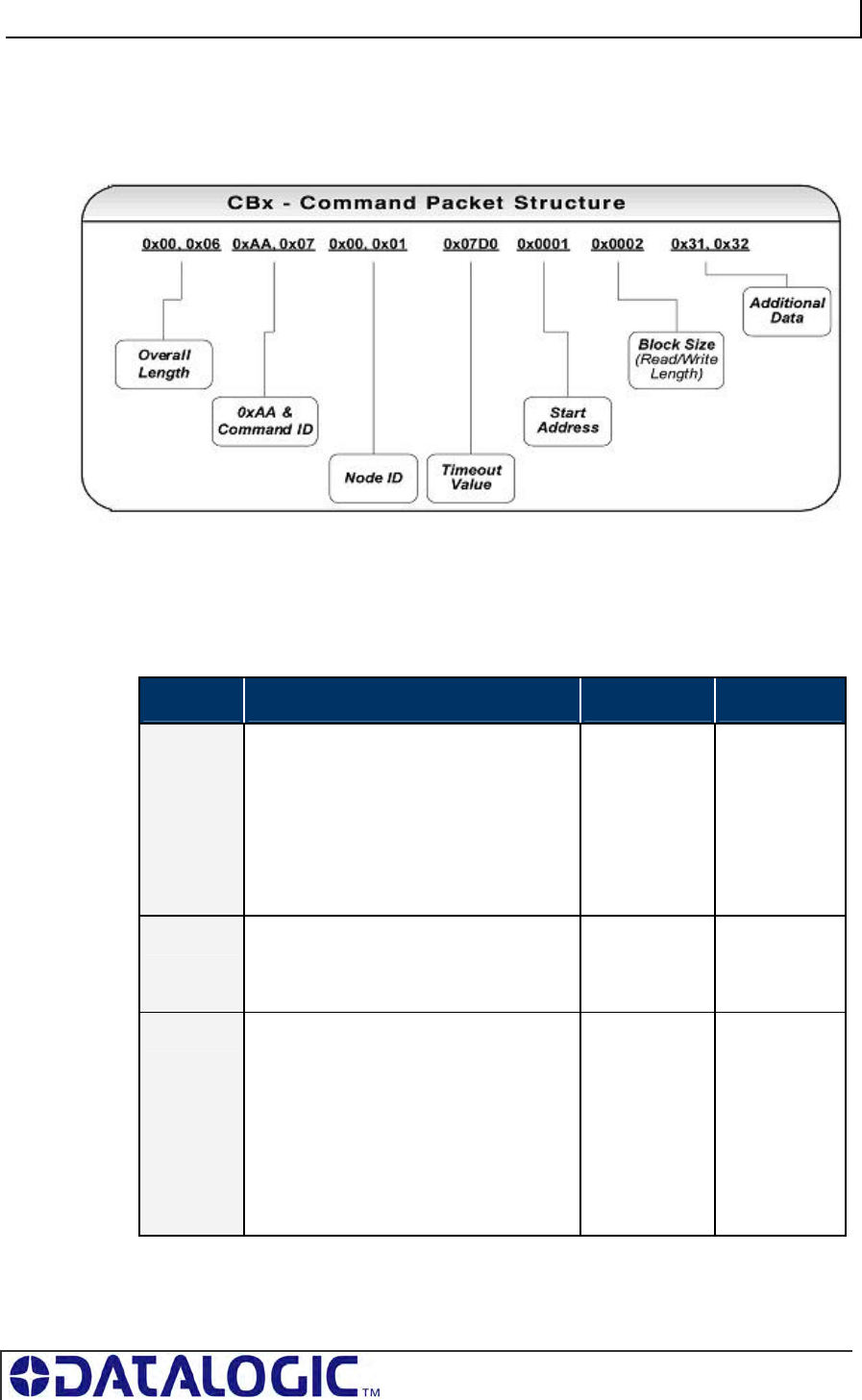
COBALT UHF-SERIES CHAPTER 5: COMMAND PROTOCOLS
PAGE 68 OF 140
5.5.2 CBx - Command Packet Structure
As noted, CBx commands contain a minimum of six words. Below is the structure of
a standard CBx command packet.
Table 5-12: CBx Command Packet Structure
CBx Command Packet Structure
(MSB = Most Significant Byte, LSB = Least Significant Byte)
WORD # COMMAND PACKET ELEMENT MSB LSB
01 Overall Length: 2-byte integer indicating
the number of 16-bit “words” in the
command packet.
Note: this value will always be at least 6,
as each command has a minimum of 12-
bytes (or 6 words). Overall Length will
increase when additional data words are
used in the command (for fills, writes, etc.).
0x00 0x06 +
(number of
additional data
words, if any)
02 0xAA in MSB
Command ID: single-byte value in LSB
indicates command to perform
0xAA <Command
ID>
03 0x00 in MSB
Node ID: LSB value indicates the Node ID
number of the device to which the
command is intended.
Note: this value must be 0x20 (Node ID
32) when the command is directed to a
Gateway or Hub, and must be 0x01 (Node
ID 01) when the command is directed to a
Cobalt IND controller.
0x00 <Node ID>
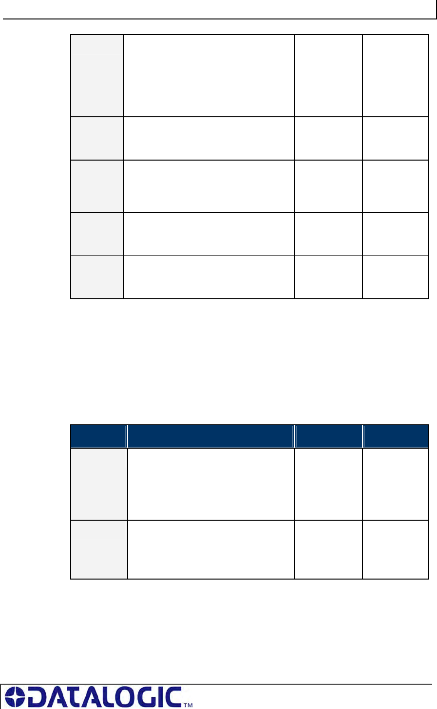
COBALT UHF-SERIES CHAPTER 5: COMMAND PROTOCOLS
PAGE 69 OF 140
04 Timeout Value: 2-byte integer
representing the length of time allowed for
the completion of the command (when
applicable). Measured in one-millisecond
increments, the Timeout Value can have a
value of 0x0001 to 0xFFFE (1 - 65,534
milliseconds).
<Timeout
MSB>
<Timeout
LSB>
05 Start Address: 2-byte integer indicating
the location of tag memory where a read or
write operation will begin (when applicable)
<Start MSB> <Start LSB>
06 Block Size: 2-byte integer indicating the
number of bytes that are to be read from or
written to a tag during the operation (when
applicable)
<Size MSB> <Size LSB>
07 Additional Data: (bytes 1 & 2) used to
hold 2-bytes of data used for writes and
fills (when applicable)
<D1> <D2>
08 Additional Data: (bytes 3 & 4) used to
hold an additional 2-bytes of data for writes
(when applicable)
<D3> <D4>
Table 5-13: CBx Command Packet Structure
5.5.3 CBx Response Packet Structure
After executing a command, the controller will generate a host-bound response
message. The response message will contain EITHER the results of the attempted
command or an error code indicating the reason the operation could not be
completed successfully. Below is the structure of a standard CBx response packet.
CBx Response Packet Structure
WORD # RESPONSE PACKET ELEMENT MSB LSB
01 Overall Length: 2-byte integer indicating
the number of “words” in the response
packet. This value will always be at least
6 words.
0x00 0x06 +
(number of
additional data
words
retrieved, if
any)
02 0xAA in MSB
Command Echo: single-byte LSB value
identifies the command that was
performed.
0xAA <Command
Echo>
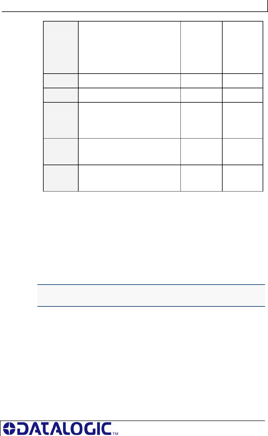
COBALT UHF-SERIES CHAPTER 5: COMMAND PROTOCOLS
PAGE 70 OF 140
03 Instance Counter:
in MSB
(see description on following page)
Node ID Echo: Value in LSB identifies
the Node ID of the device that performed
the command and/or generated the
response (will always be 0x20 for
Gateway/Hub, and 0x01 for Cobalt IND)
<Instance
Counter>
<Node ID
Echo>
04 Month and Day Timestamp <Month> <Day>
05 Hour and Minute Timestamp <Hour> <Minute>
06 Second Timestamp in MSB
Additional Data Length: Value in LSB
indicates the number of additional bytes
retrieved (when applicable)
<Second> <Additional
Data Length>
07 Retrieved Data: (bytes 1 & 2) used to
hold 2-bytes of retrieved data (when
applicable)
<B1> <B2>
08 Retrieved Data: (bytes 3 & 4) used to
hold an additional 2-bytes of retrieved
data (when applicable)
<B3> <B4>
Table 5-14: CBx Response Packet Structure
INSTANCE COUNTER
The Instance Counter is a one-byte value used to track the number of responses
generated by each Node ID. Instance Counter values are stored in the internal RAM
of the Gateway/Hub and are incremented by one following each response. If, for
example, the controller at Node 01 has generated 10 responses, the Instance
Counter value for Node 01 in the Gateway/Hub will read 10 (0x0A). When power is
cycled to the Gateway/Hub, the Instance Counter values for all nodes (and for the
Gateway/Hub itself) will be reset to zero (0x00).
NOTE: UHF-CNTL-IND-02 Controllers are capable of storing their own Instance
Counter values. Likewise, when power is cycled to either device, their Instance Counter
values will be reset to zero.
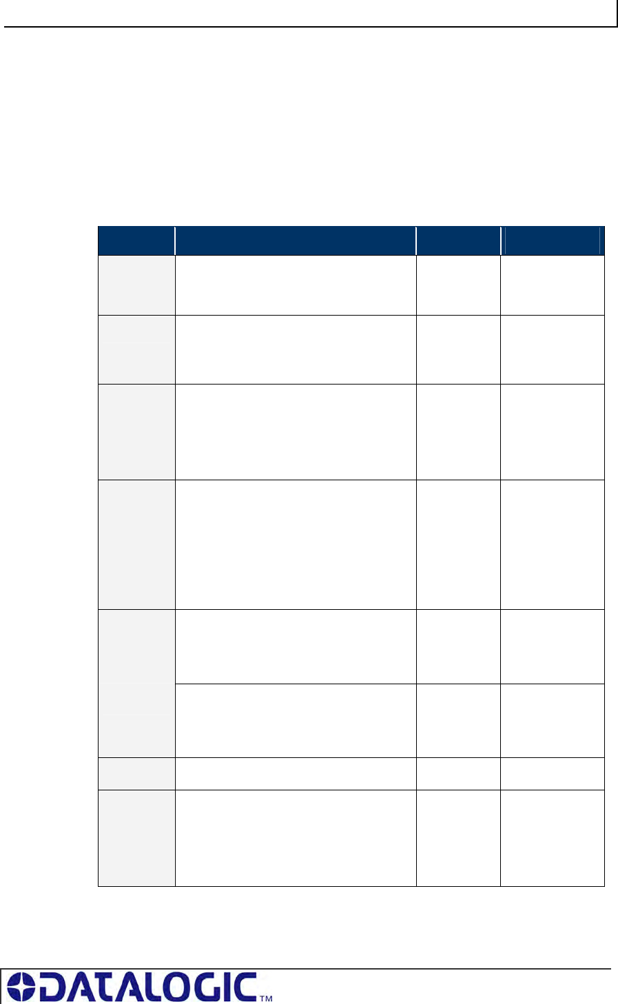
COBALT UHF-SERIES CHAPTER 5: COMMAND PROTOCOLS
PAGE 71 OF 140
5.5.4 CBx Multi-Tag Command Packet Structure
CBx Multi-tag Commands instruct a specified controller to read from or write to
several tags at once when multiple tags are simultaneously within RF range. It is also
possible to single-out and read from or write to one tag (identified by its unique tag ID
number) when multiple tags are present in the RF field simultaneously.
Below is the structure of a basic CBx multi-tag command packet.
CBx Multi-tag Command Packet Structure
WORD # COMMAND PACKET ELEMENT MSB LSB
01 Overall Length: 2-byte integer value
indicating the number of “words” in the
command packet.
0x00 0x08 + (number
of any additional
data words)
02 0xAA in MSB
Command ID: LSB value indicates
command to perform
0xAA <Command ID>
03 0x00 in MSB
Node ID: LSB value indicates the Node ID
number of the controller to which the
command is intended (must be 0x01 for –
Cobalt IND models)
0x00 0x01
04 Timeout Value: 2-byte integer represents
the maximum length of time allowed for
the completion of the command,
measured in one-millisecond increments,
where 0x0BB8 = 3000 x .001 = 3
seconds. The Timeout Value can have a
value of 0x0001 to 0xFFFE (1 - 65,534
milliseconds).
0x0B 0xB8
05 Start Address: 2-byte integer indicating
the location of tag memory where a read
or write operation will begin (when
applicable).
<Start MSB> <Start LSB>
06 Block Size: 2-byte integer indicating the
number of bytes that are to be read from
or written to an RFID tag during the
operation (when applicable).
<Size MSB> <Size LSB>
07 Reserved for future use 0x00 0x00
08 Tag Limit: Single-byte MSB value for the
maximum # of tags expected in RF range,
up to 100 (see description in Section
1.3.4).
0x00 in LSB
0x64
(100 tags
max Tag
Limit)
0x00
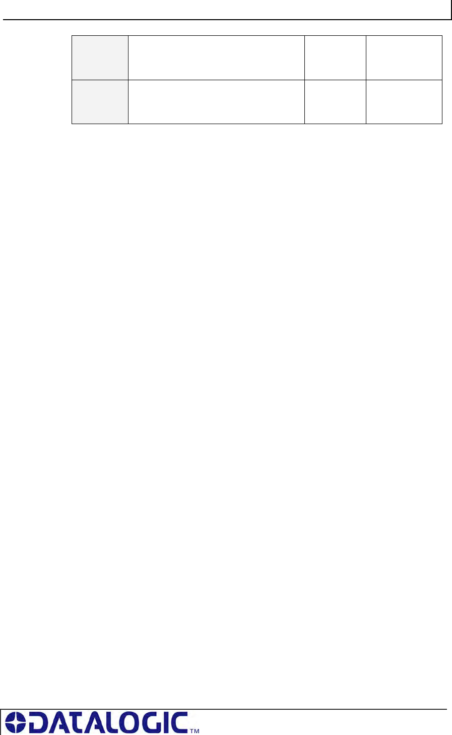
COBALT UHF-SERIES CHAPTER 5: COMMAND PROTOCOLS
PAGE 72 OF 140
09 Additional Data Byte Values 1 & 2:
holds 2 bytes of data used for fills, writes,
etc. (when applicable)
<D1> <D2>
10 Additional Data Byte Values 3 & 4:
holds an extra 2-bytes for write operations
if needed (when applicable)
<D3> <D4>
Table 5-15: CBx Multi-Tag Command Packet Structure
5.5.5 CBx Multi-Tag Command Packet Elements
Tag Limit
The Tag Limit parameter holds a one-byte value that indicates the maximum number
of tags expected simultaneously in RF range for the given command operation. This
parameter allows users to limit the number of attempted read/write operations the
controller will make per execution (users do not have to wait for the Timeout to
expire).
The Tag Limit value should be set in relation to the maximum number of tags that
could possibly be present in the reading field at any one time. Setting a high value
increases the number of tags that are expected in the antenna’s RF field. Setting a
low value can speed up multi-tag operations when only a small number of tags could
be present at any given moment.
Setting the proper value is therefore a tradeoff between the number of expected tags
in the reading field, and the time required to read/write to them. The permitted values
range from zero to 100 (0x00 – 0x64).
The Tag Limit parameter resides directly after the “Anti-collision Mode” parameter in
the command string (when applicable).
Timeout Value
Multi-tag commands also contain a two-byte Timeout Value parameter that is used
to limit the length of time for which the controller will attempt to complete a given
operation.
It is important to set a realistic Timeout Value that permits enough time for the
controller to read/write to all tags specified in the command. Processing multiple-tag
operations requires a longer time period than does the execution of single-tag
commands.
The value is expressed in one-millisecond increments, with a maximum value of
0xFFFE (65,534 milliseconds) or approximately 60 seconds. It is recommended that
users allow at least 100ms per tag for multi-tag read operations and 150ms per tag
for multi-tag writes.
Using a Timeout Value that is too short may cause the controller to inadvertently
“time out” before the data has been successfully read from or written to all tags in RF
range. For time critical applications, the optimal Timeout Value should be obtained
through rigorous performance testing.
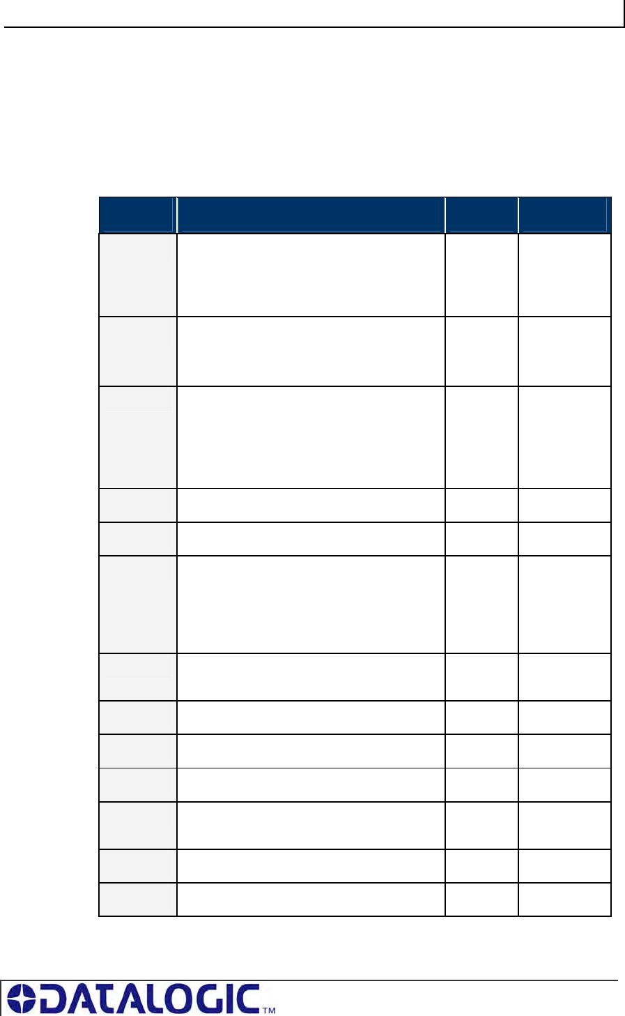
COBALT UHF-SERIES CHAPTER 5: COMMAND PROTOCOLS
PAGE 73 OF 140
5.5.6 CBx Multi-Tag Response Packet Structures
When executing multi-tag commands designed to retrieve information from several
tags at once (for example CBx Command 0x92: Multi-Tag Read ID and Data All), the
RFID controller will generate separate host-bound response packets for each tag that
has been read. Below is the structure of a basic CBx multi-tag response packet
generated by the controller at Node 01.
CBx Multi-tag Response Packet Structure (One Packet for Each Tag Read)
WORD # RESPONSE PACKET ELEMENT MSB LSB
01 Overall Length: 2-byte integer indicates the
number of “words” in the response packet.
0x00 0x06 +
(number of
additional
words
retrieved)
02 0xAA in MSB
Command Echo: single-byte value identifies
the command that was performed in LSB
0xAA <Command
Echo>
03 Instance Counter: 1-byte MSB value indicates
number of responses generated by the Node ID
identified in the LSB.
Node ID Echo: 1-byte value indicates the Node
ID of the RFID controller that performed the
command.
<IC> 0x01
04 Month and Day Timestamp <Month> <Day>
05 Hour and Minute Timestamp <Hour> <Minute>
06 Second Timestamp in MSB
Additional Data Length: single-byte LSB
value indicates the number of additional bytes
retrieved, includes both Tag ID and Read Data
bytes (when applicable)
<Second> <N-bytes>
07 Tag ID bytes 1 and 2: holds the first two bytes
of the Tag ID number
<ID byte 1> <ID byte 2>
08 Tag ID bytes 3 and 4 <ID byte 3> <ID byte 4>
09 Tag ID bytes 5 and 6 <ID byte 5> <ID byte 6>
10 Tag ID bytes 7 and 8 <ID byte 7> <ID byte 8>
11 Read Data bytes 1 and 2: holds 2 bytes of
retrieved data from tag read operations
<D01> <D02>
… … … …
18 Read Data bytes 15 and 16 <D15> <D16>
Table 5-16: CBx Multi-Tag Response Packet Structure
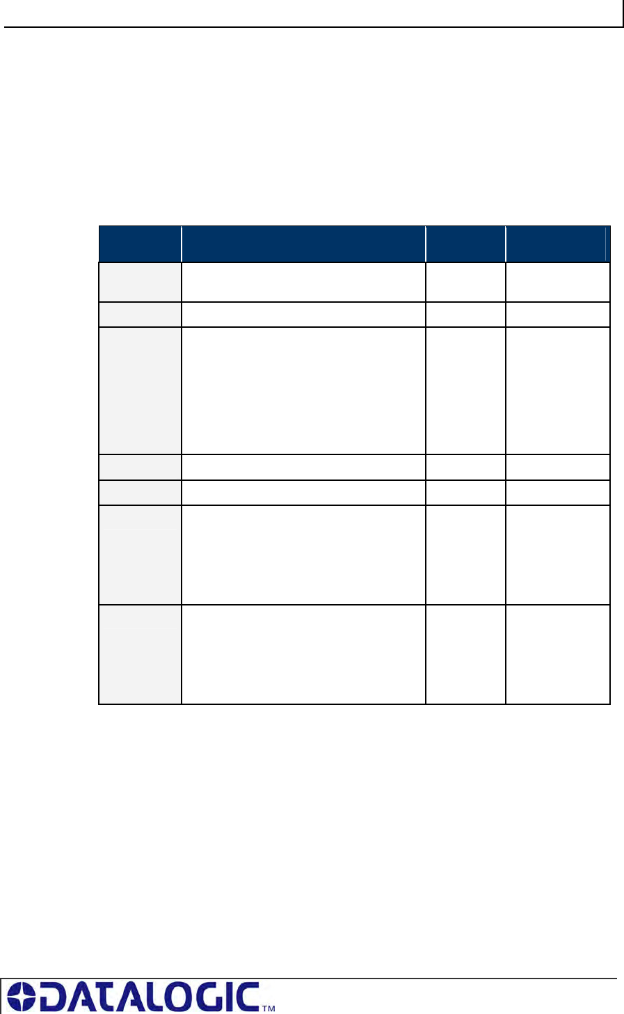
COBALT UHF-SERIES CHAPTER 5: COMMAND PROTOCOLS
PAGE 74 OF 140
5.5.7 CBx Multi-Tag Response Final Termination Packet
Structure
After the RFID controller has issued response packets for each tag identified and/or
read, a final termination packet is generated. Below is the structure of a standard
CBx multi-tag response final termination packet generated by the controller at Node
01.
CBx Multi-tag Response Final Termination Packet Structure
WORD # PACKET ELEMENT MSB LSB
01 Overall Length: 2-byte integer indicates
the number of “words” in the packet.
0x00 0x07
02 0xAA in MSB, 0xFF in LSB 0xAA 0xFF
03 Instance Counter: 1-byte value indicates
the number of responses generated by the
Node ID identified in the LSB (this value is
not to be confused with the number of tags
read during a single operation)
Node ID Echo: 1-byte value indicates the
Node ID of the controller that performed
the command.
<IC> 0x01
04 Month and Day Timestamp <Month> <Day>
05 Hour and Minute Timestamp <Hour> <Minute>
06 Second Timestamp
in MSB
Additional Data Length: Single-byte LSB
value indicates the number of additional
bytes retrieved (value will usually = 2, for
Number of Tags Read/Written and
Status)
<Second> 0x02
07 Number of Tags Read/Written in MSB,
identifies the number of tags read from or
written to during the operation
Status in LSB (0x00 = operation
completed successfully, 0x07 = Read Tag
ID failed / Tag Not Found)
<N-tags> 0x00
Table 5-17: CBx Multi-Tag Response Final Termination Packet Structure
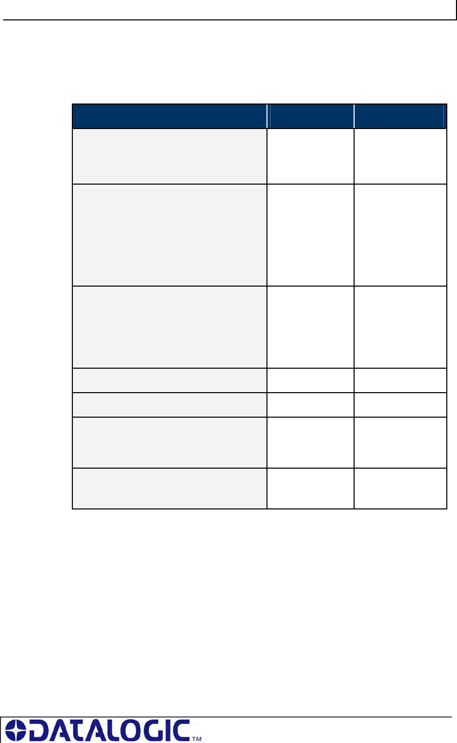
COBALT UHF-SERIES CHAPTER 5: COMMAND PROTOCOLS
PAGE 75 OF 140
5.5.8 CBx Protocol: Error Response Packet Structure
A one-byte Error Code will be returned in the MSB of the seventh data word of an
error response packet (followed by 0x00 in the LSB).
ERROR RESPONSE ELEMENT MSB LSB
Overall Length: 2-byte value indicating the
number of “words” in the Response Packet.
This value will always be at least 7 words (6 +
1 for the error code).
0x00 0x07
Error Flag: 0xFF in the MSB indicates that an
error occurred.
Error Information Byte: 0xFF in the LSB
indicates that a controller-based error
occurred. Any value other than 0xFF indicates
that a Gateway or Hub-based error occurred
(and indicates the command that was
attempted when the error occurred).
0xFF 0xFF
Instance Counter: This 1-byte value tallies
the number of responses from a given Node
ID.
Node ID Echo: 1-byte value in LSB indicates
the Node ID of the controller that experienced
or generated the error. (Cobalt -IND = 01)
<IC> 0x01
Month and Day Timestamp <Month> <Day>
Hour and Minute Timestamp <Hour> <Minute>
Seconds Timestamp in MSB
Additional Data Length in LSB (1 byte for
“Error Code”)
<Seconds> 0x01
Error Code: 1-byte Error Code in MSB
0x00 in LSB
<Error Code> 0x00
Table 5-18: CBx - Error Response Packet Structure
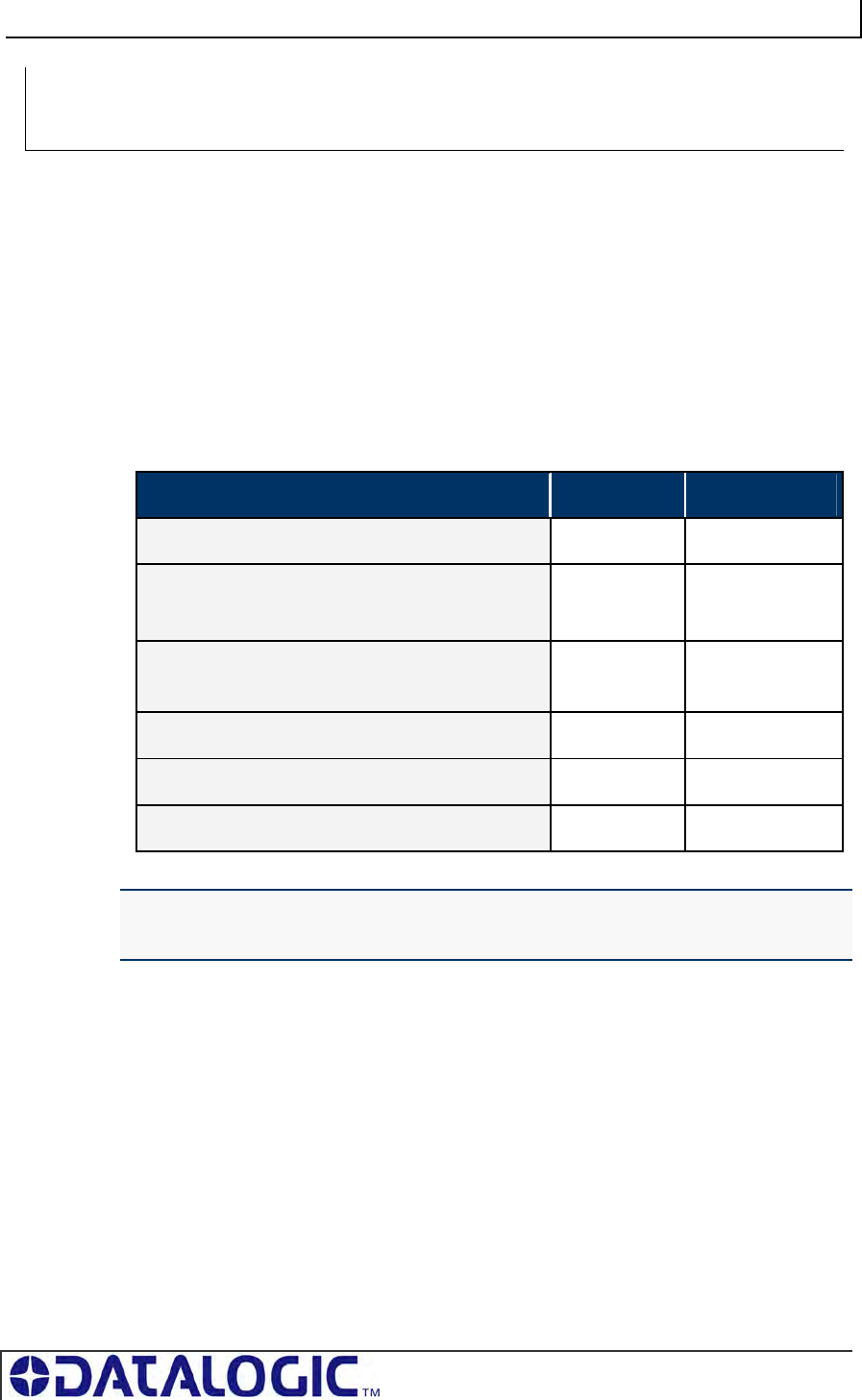
COBALT UHF-SERIES CHAPTER 5: COMMAND PROTOCOLS
PAGE 76 OF 140
COMMAND 0XC2 - DESCRIPTION
The Read EPC Command instructs the controller to retrieve the EPC memory area
of a single tag UHF Class1 Gen2.
COMMAND 0XC2 - CBX EXAMPLE
This example instructs the controller to read the EPC memory from a tag. A Timeout
Value of 2 seconds (0x07D0 = 2000 x one-millisecond increments) is set for the
completion of the command.
Command from Host
PARAMETER FIELD MSB LSB
Overall Length of Command (in words) 0x00 0x06
0xAA in MSB
Command ID in LSB (0xC2)
0xAA 0xC2
0x00 in MSB
Node ID in LSB
0x00 0x01
Timeout Value 0x07 0xD0
Not Used (0x00, 0x00)* 0x00 0x00
Not Used (0x00, 0x00)* 0x00 0x00
*NOTE: even when one or more command parameters are not used in a particular
command, the parameter’s two bytes must still be accounted for in the Overall Length.
Include all “zeroes” for these bytes (0x00, 0x00).
CBX SINGLE-TAG RFID COMMAND 0XC2:
READ EPC CODE
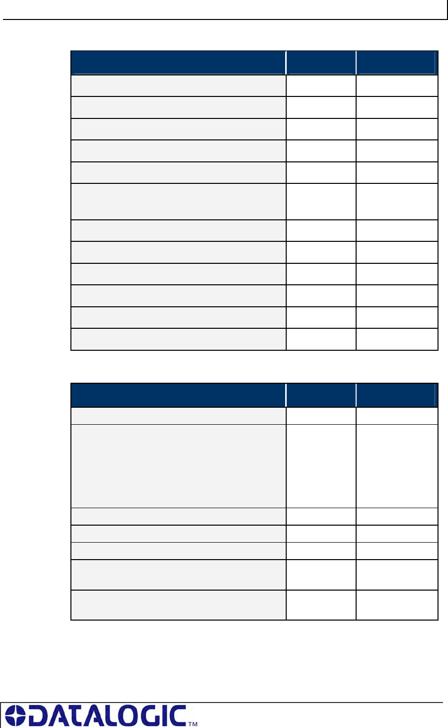
COBALT UHF-SERIES CHAPTER 5: COMMAND PROTOCOLS
PAGE 77 OF 140
Response from Controller (Tag Found)
PARAMETER FIELD MSB LSB
Overall Length of Response (in words) 0x00 0x0C
0xAA in MSB, Command Echo in LSB 0xAA 0xC2
Instance Counter in MSB, Node ID Echo in LSB <IC> 0x01
Month and Day Timestamp: (March 19th) 0x03 0x13
Hour and Minute Timestamp: (10:11: AM) 0x0A 0x0B
Seconds Timestamp in MSB: (:36 seconds)
Additional Data Length in LSB: (0x0C)
0x24 0x0C
EPC (bytes 1 & 2) 0xE0 0x04
EPC (bytes 3 & 4) 0x01 0x00
EPC (bytes 5 & 6) 0x00 0x2E
EPC (bytes 7 & 8) 0xEB 0x34
EPC (bytes 9 & 10) 0x11 0x35
EPC (bytes 11 & 12) 0x16 0xAD
Response from Controller (Tag Not Found)
PARAMETER FIELD MSB LSB
Overall Length of Response (in words) 0x00 0x07
Error Flag in MSB = 0xFF
Error Information Byte in LSB
0xFF in the LSB indicates that a controller-based
error occurred. Any value other than 0xFF indicates
that a Gateway or Hub-based error occurred (and
identifies the command that was attempted when the
error occurred).
0xFF 0xFF
Instance Counter in MSB, Node ID Echo in LSB <IC> 0x01
Month and Day Timestamp: (March 19th) 0x03 0x13
Hour and Minute Timestamp: (10:11: AM) 0x0A 0x0B
Seconds Timestamp in MSB: (:36 seconds)
Additional Data Length in LSB: (0x01)
0x24 0x01
Error Code in MSB (0x07 = “Tag Not Found”)
0x00 in LSB
0x07 0x00
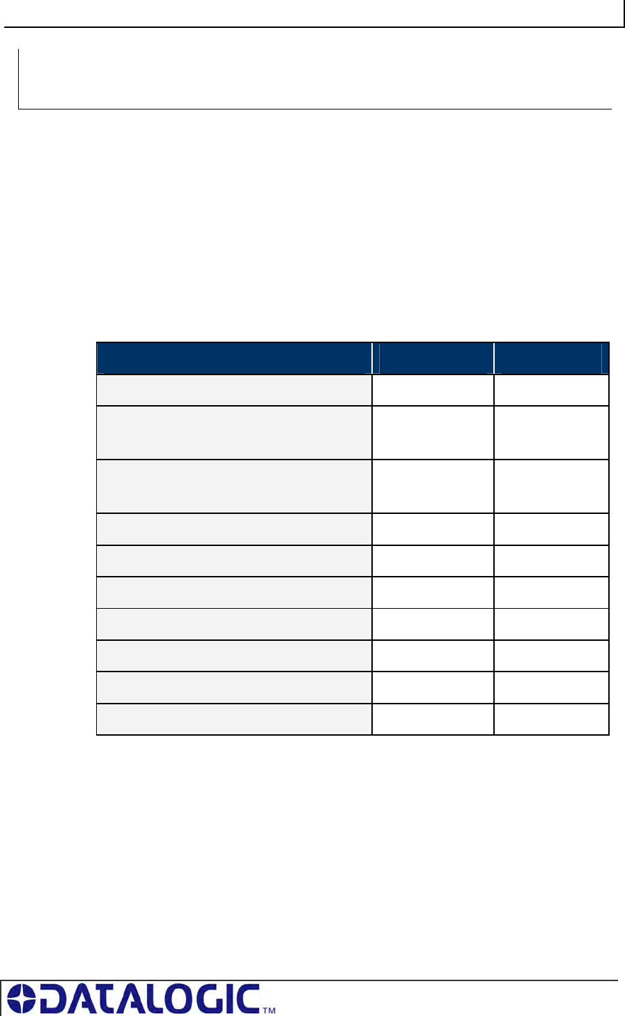
COBALT UHF-SERIES CHAPTER 5: COMMAND PROTOCOLS
PAGE 78 OF 140
COMMAND 0XC3 - DESCRIPTION
The Write EPC Command instructs the controller to write the EPC memory area of a
single tag UHF Class1 Gen2.
COMMAND 0XC3 - CBX EXAMPLE
This example instructs the controller to write the specified bytes in the EPC memory
of a tag. A Timeout Value of 2 seconds (0x07D0 = 2000 x one-millisecond
increments) is set for the completion of the command.
Command from Host
PARAMETER FIELD MSB LSB
Overall Length of Command (in words) 0x00 0x0A
0xAA in MSB
Command ID in LSB (0x06)
0xAA 0xC3
0x00 in MSB
Node ID in LSB
0x00 0x01
Timeout Value (measured in ms) 0x07 0xD0
EPC Write Data (bytes 1 and 2) 0x48 0x45
EPC Write Data (bytes 3 and 4) 0x4C 0x4C
EPC Write Data (bytes 5 and 6) 0x58 0x45
EPC Write Data (bytes 7 and 8) 0xAB 0x6F
EPC Write Data (bytes 9 and 10) 0x4E 0x45
EPC Write Data (byte 11 and 12) 0x4F 0x00
CBX SINGLE-TAG RFID COMMAND 0XC3:
WRITE EPC CODE
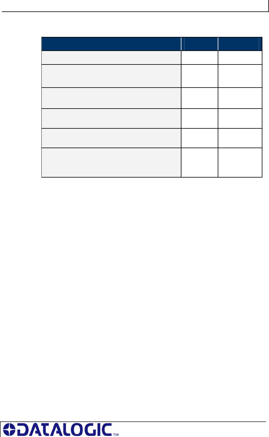
COBALT UHF-SERIES CHAPTER 5: COMMAND PROTOCOLS
PAGE 79 OF 140
Response from Controller
PARAMETER FIELD MSB LSB
Overall Length of Response (in words) 0x00 0x06
0xAA in MSB
Command Echo in LSB
0xAA 0xC3
Instance Counter in MSB
Node ID Echo in LSB
<IC> 0x01
Month and Day Timestamp:
(March 19th)
0x03 0x13
Hour and Minute Timestamp:
(10:11: AM)
0x0A 0x0B
Seconds Timestamp in MSB
(:36 seconds)
0x00 in LSB
0x24 0x00
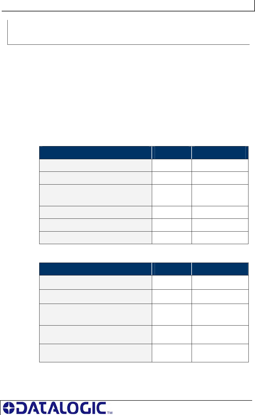
COBALT UHF-SERIES CHAPTER 5: COMMAND PROTOCOLS
PAGE 80 OF 140
COMMAND 0XC4 - DESCRIPTION
The Multi-Tag Read EPC Code is used to retrieve the EPC data from all tags within
RF range. A final termination packet is sent when the Timeout Value expires.
C
OMMAND 0XC4 - CBX EXAMPLE
This example instructs the controller to read the EPC data from each tag in range. A
Timeout Value of 3 seconds (0x0BB8 = 3000 x 1msec increments) is set for the
completion of the command.
Command from Host
PARAMETER FIELD MSB LSB
Overall Length of Command (in words) 0x00 0x06
0xAA in MSB, Command ID in LSB 0xAA 0xC4
0x00 in MSB
Node ID in LSB
0x00 0x01
Timeout Value 0x0B 0xB8
Tag Limit in MSB, 0x00 in LSB 0x64 0x00
Not Used (0x00, 0x00)* 0x00 0x00
Response for Each Tag Found
PARAMETER FIELD MSB LSB
Overall Length of Response (in words) 0X00 0X0C
0xAA in MSB, Command Echo in LSB 0XAA 0XC4
Instance Counter in MSB
Node ID Echo in LSB
<IC> 0X01
Month and Day Timestamp:
(March 19th)
0x03 0x13
Hour and Minute Timestamp:
(10:11: AM)
0x0A 0x0B
MULTI-TAG RFID COMMAND 0XC4:
READ EPC CODE
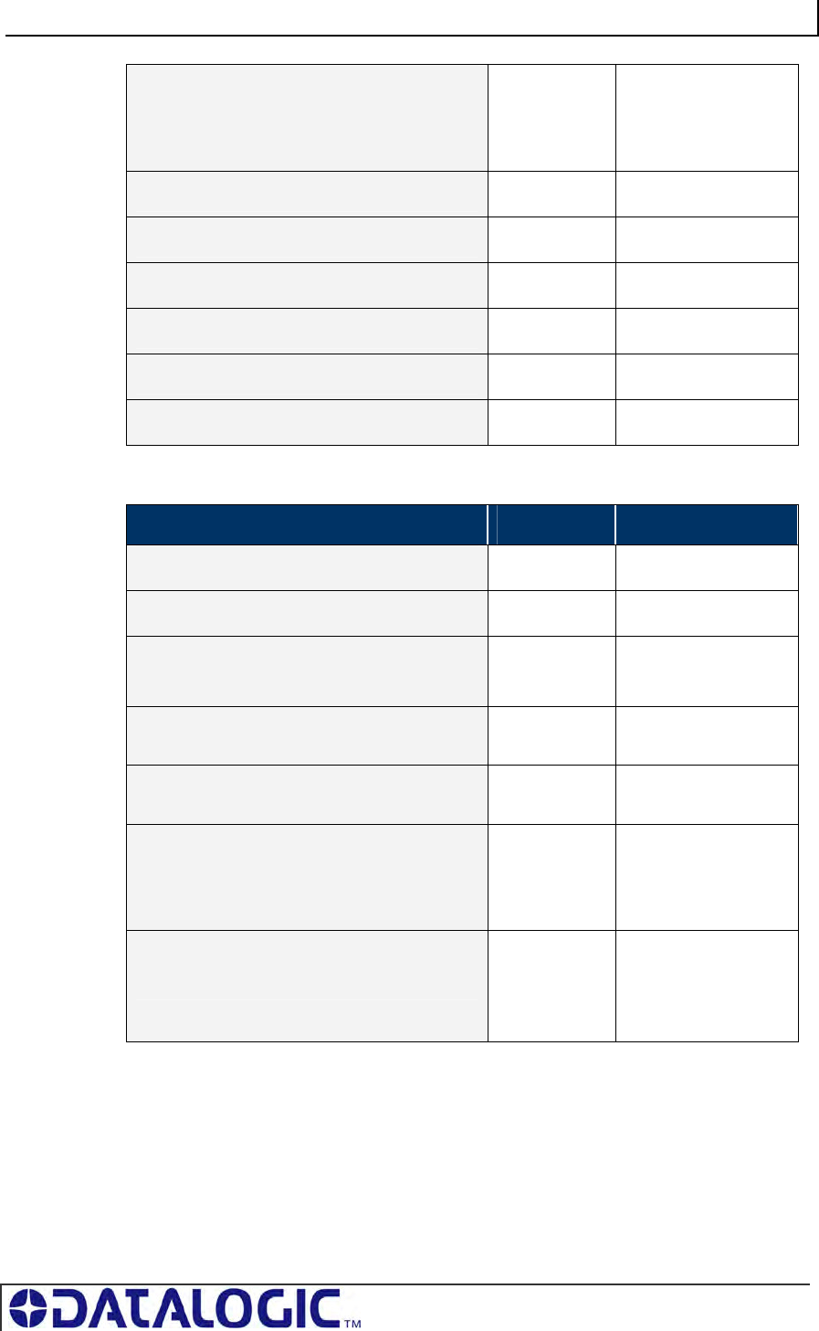
COBALT UHF-SERIES CHAPTER 5: COMMAND PROTOCOLS
PAGE 81 OF 140
Seconds Timestamp in MSB
(:36 seconds)
Additional Data Length in LSB (number of
additional bytes returned)
0X24 0X0C
EPC ID (bytes 1 and 2) <ID1> <ID2>
EPC ID (bytes 3 and 4) <ID3> <ID4>
EPC ID (bytes 5 and 6) <ID5> <ID6>
EPC ID (bytes 7 and 8) <ID7> <ID8>
EPC ID (bytes 9 and 10) <ID9> <ID10>
EPC ID (bytes 11 and 12) <ID11> <ID12>
Final Response Packet
PARAMETER FIELD MSB LSB
Overall Length of Response (in words) 0X00 0X07
0xAA in MSB, 0xFF in LSB 0XAA 0XFF
Instance Counter in MSB
Node ID Echo in LSB
<IC> 0X01
Month and Day Timestamp:
(March 19th)
0x03 0x13
Hour and Minute Timestamp:
(10:11: AM)
0x0A 0x0B
Seconds Timestamp in MSB
(:36 seconds)
Additional Data Length in LSB (2 bytes:
“Number of Tags” and “Status”)
0X24 0X02
Number of Tags Found in MSB
Status in LSB
<NUMBER OF
TAGS FOUND>
<0X00 = OPERATION
COMPLETED
SUCCESSFULLY, 0X07
= READ TAG ID FAILED
/ TAG NOT FOUND>
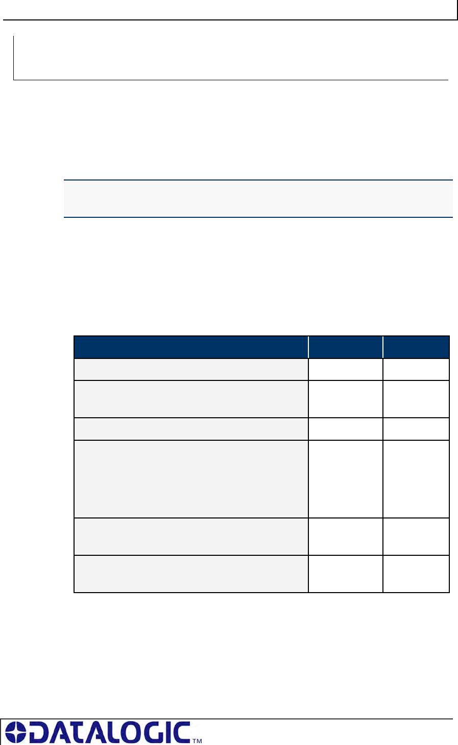
COBALT UHF-SERIES CHAPTER 5: COMMAND PROTOCOLS
PAGE 82 OF 140
COMMAND 0XC0 – DESCRIPTION
The Set UHF Configuration command is used to set (configure or modify) the
controller’s UHF configuration parameters and settings to the controller’s flash
memory.
IMPORTANT: it is recommended that users first run Command 0xC1: Get UHF
Configuration and make note of their current controller configuration values prior to
executing this command.
COMMAND 0XC0 - CBX EXAMPLE
This example permits the user to modify or write the indicated configuration settings
to the controller’s flash memory. The total number of bytes available for this purpose
is nine.
Command from Host
PARAMETER FIELD MSB LSB
Overall Length of Command (in words) 0x00 0x08
0xAA in MSB
Command ID in LSB: (0x43)
0xAA 0xC0
0x00 in MSB, Node ID in LSB 0x00 0x01
UHF Configuration Byte 1 in MSB
UHF Configuration Byte 2 in LSB
These two-bytes represent the Reader Output Power
(value from 0 to 500 mW).
<Byte 1> <Byte 2>
UHF Configuration Byte 3 in MSB
UHF Configuration Byte 4 in LSB
<Reserved> * <Reserved>
*
UHF Configuration Byte 5 in MSB
UHF Configuration Byte 6 in LSB
<Reserved> * <Reserved>
*
CONTROLLER SPECIFIC COMMAND 0XC0:
SET UHF CONFIGURATION
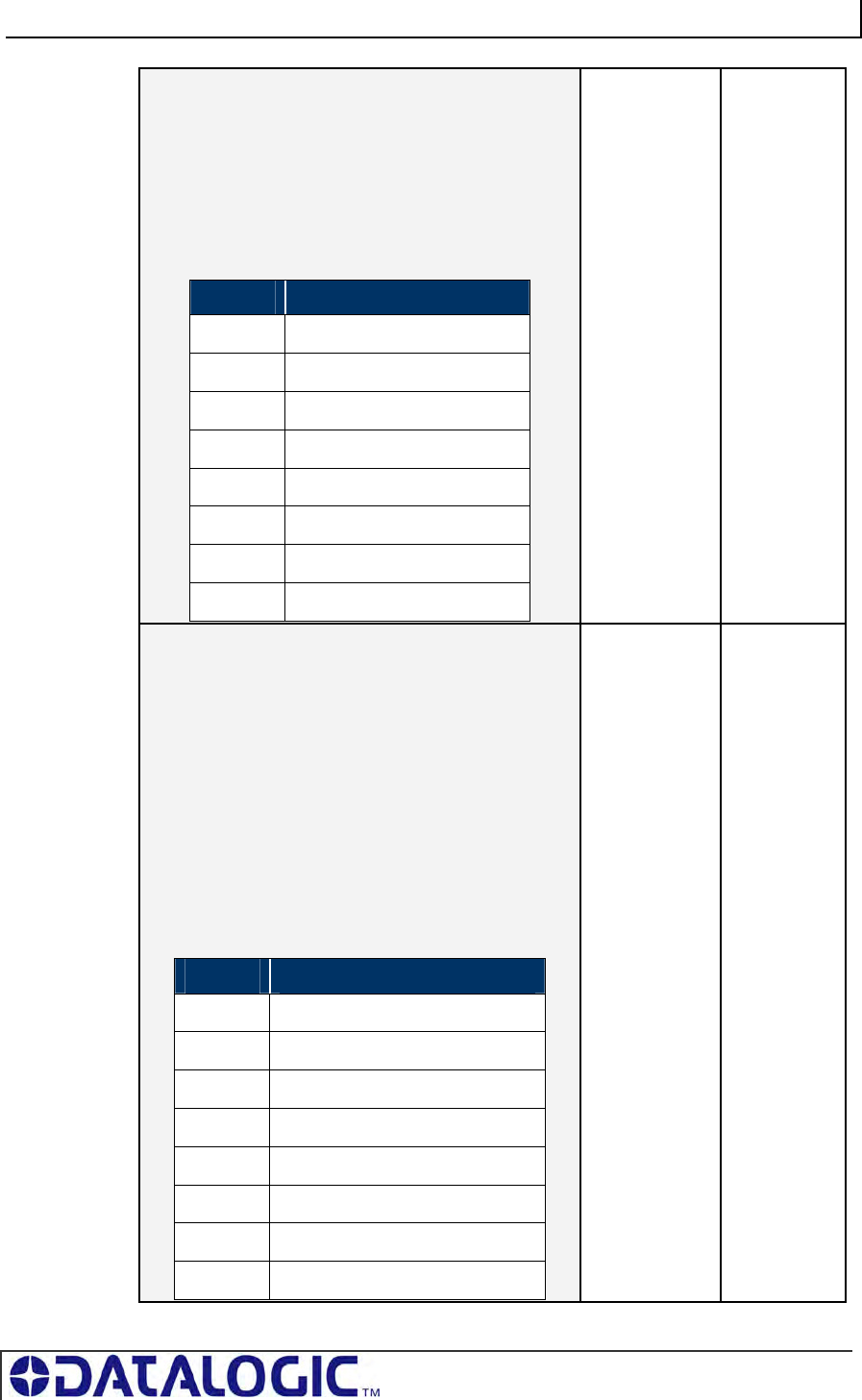
COBALT UHF-SERIES CHAPTER 5: COMMAND PROTOCOLS
PAGE 83 OF 140
UHF Configuration Byte 7 in MSB
UHF Configuration Byte 8 in LSB
Byte 8 in LSB is partially reserved (see table below). This
byte permits the user to select the specific UHF channel
through which commands are transmitted. The user can
write a value between o and 9 in bits from 4 to 7
UHF Config. Byte 8 - Table
BIT Description
0 Reserved*
1 Reserved*
2 Reserved*
3 Reserved*
4 <Channel ID value>
5 <Channel ID value>
6 <Channel ID value>
7 <Channel ID value>
<Reserved> * <Partially
Reserved>
UHF Configuration Byte 9 in MSB
0x00 in LSB (not used)
Byte 9 in MSB is partially reserved (see table below).This
byte permits the user to enable/disable the Choose
Nearest One property.
If the Choose Nearest One property is disabled, an error
response is generated whenever a single-tag read/write
command is executed in a multi-tag environment.
If the Choose Nearest One property is enabled, the
read/write command is executed on the tag with the
strongest signal.
UHF Config. Byte 9 - Table
BIT Description
0 Reserved*
1 <Choose Nearest One option>
2 Reserved*
3 Reserved*
4 Reserved*
5 Reserved*
6 Reserved*
7 Reserved*
<Partially
Reserved>
0x00
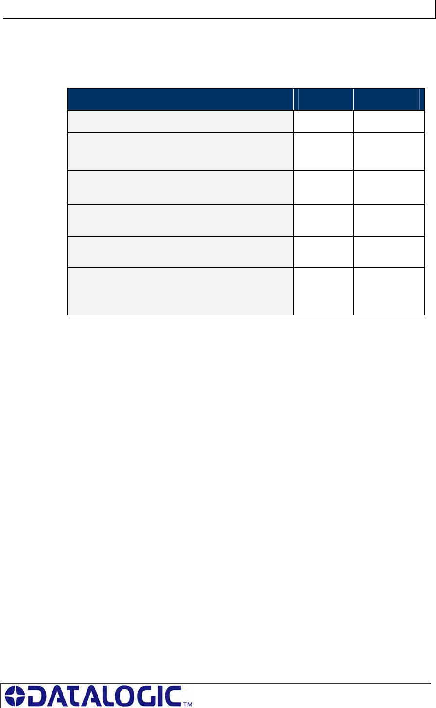
COBALT UHF-SERIES CHAPTER 5: COMMAND PROTOCOLS
PAGE 84 OF 140
*Leave the default value retrieved through Command 0xC1: Get UHF Configuration
Response from Controller
PARAMETER FIELD MSB LSB
Overall Length of Response (in words) 0x00 0x06
0xAA in MSB
Command Echo in LSB
0xAA 0xC0
Instance Counter in MSB
Node ID Echo in LSB
<IC> 0x01
Month and Day Timestamp:
(March 19th)
0x03 0x13
Hour and Minute Timestamp:
(10:11: AM)
0x0A 0x0B
Seconds Timestamp in MSB
(:36 seconds)
0x00 in LSB
0x24 0x00
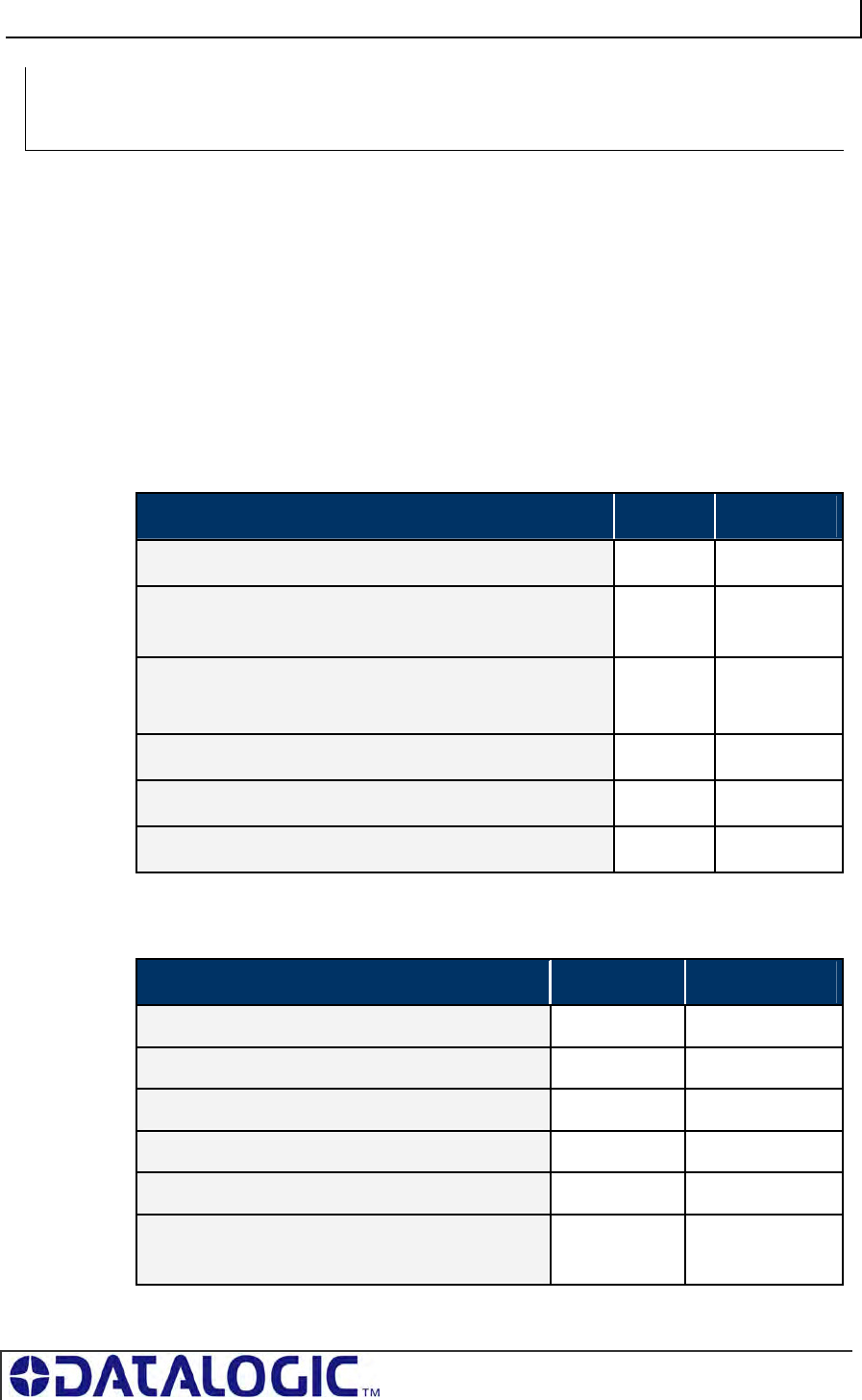
COBALT UHF-SERIES CHAPTER 5: COMMAND PROTOCOLS
PAGE 85 OF 140
COMMAND 0XC1 – DESCRIPTION
The Get UHF Configuration Command instructs the controller to retrieve the
controller’s UHF configuration parameters and settings stored in the unit’s flash
memory. These are the same values that are set with Command 0xC0: Set UHF
Configuration.
COMMAND 0XC1 - CBX EXAMPLE
Through this command, the user queries a Cobalt UHF RFID controller and reads the
controller’s UHF configuration data from its flash memory.
Command from Host
PARAMETER FIELD MSB LSB
Overall Length of Command (in words) 0x00 0x06
0xAA in MSB
Command ID in LSB
0xAA 0xC1
0x00 in MSB
Node ID in LSB
0x00 0x01
Not Used (default: 0x00, 0x00) 0x00 0x00
Not Used (default: 0x00, 0x00) 0x00 0x00
Not Used (default: 0x00, 0x00) 0x00 0x00
Response from Controller
PARAMETER FIELD MSB LSB
Overall Length of Response (in words) 0x00 0x0B
0xAA in MSB, Command Echo in LSB 0xAA 0xC1
Instance Counter in MSB, Node ID Echo in LSB <IC> 0x01
Month and Day Timestamp: (March 19th) 0x03 0x13
Hour and Minute Timestamp: (10:11: AM) 0x0A 0x0B
Seconds Timestamp in MSB: (:36 seconds)
Additional Data Length in LSB: (0x0A)
0x24 0x0A
CONTROLLER SPECIFIC COMMAND 0XC1:
GET UHF CONFIGURATION
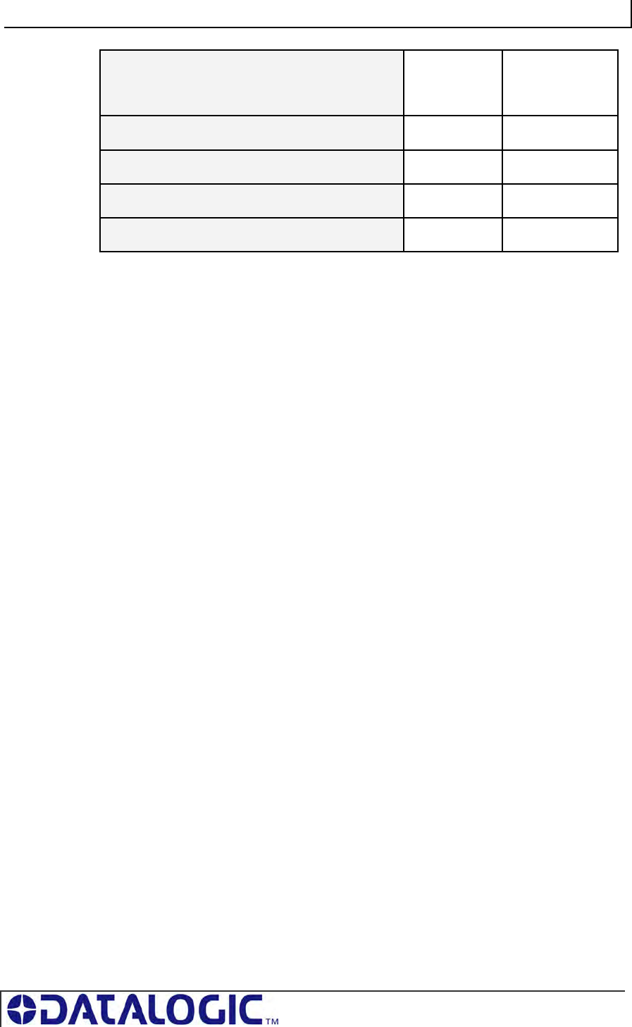
COBALT UHF-SERIES CHAPTER 5: COMMAND PROTOCOLS
PAGE 86 OF 140
UHF Configuration Bytes 1 & 2
These two bytes represent the Reader Output
Power (0÷500 mW).
<Byte 1> <Byte 2>
UHF Configuration Bytes 3 & 4 <Byte 3> <Byte 4>
UHF Configuration Bytes 5 & 6 <Byte 5> <Byte 6>
UHF Configuration Bytes 7 & 8 <Byte 7> <Byte 8>
UHF Configuration Bytes 9 & 10 <Byte 9> 0x00
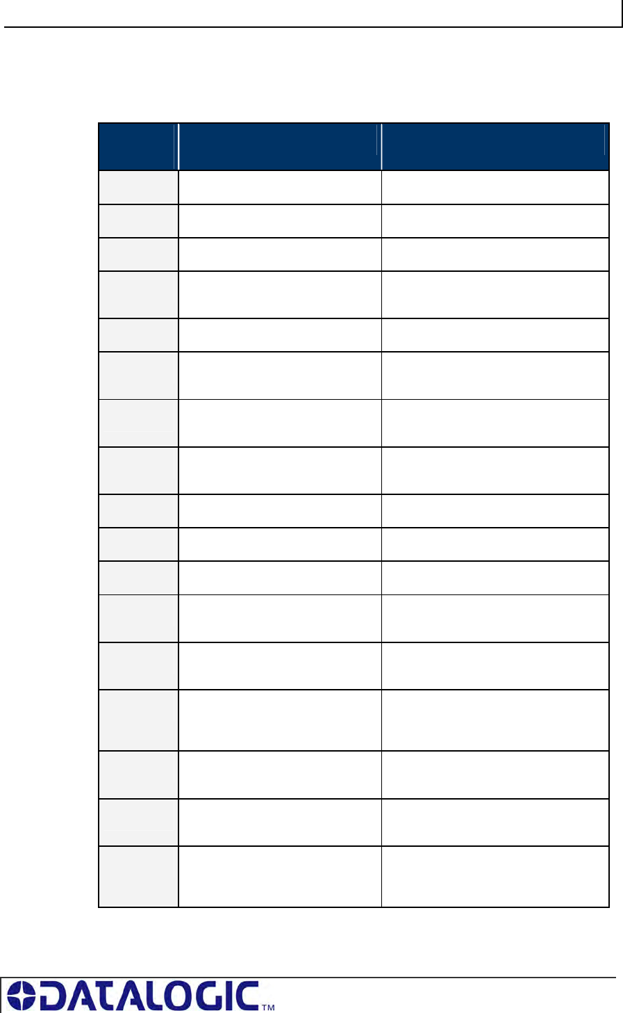
COBALT UHF-SERIES CHAPTER 5: COMMAND PROTOCOLS
PAGE 87 OF 140
5.6 ERROR CODE TABLE
ERROR
CODE
ERROR DESCRIPTION
0x04 FILL TAG FAILED Fill Tag operation failed
0x05 READ DATA FAILED Read Data operation failed
0x06 WRITE DATA FAILED Write Data operation failed
0x07 TAG NOT FOUND, TAG SEARCH
FAILED
Read Tag ID operation failed, Tag
Search operation failed
0x21 INVALID SYNTAX Command Contained a syntax error
0x30 INTERNAL CONTROLLER
ERROR
Generic internal controller error
0x31 INVALID CONTROLLER TYPE Invalid controller type (when setting
configuration)
0x32 INVALID PROGRAMMING
ADDRESS
Invalid tag programming address
specified
0x35 INVALID RESET Invalid hardware reset
0x36 SET CONFIGURATION ERROR Configuration not written
0x37 GET CONFIGURATION ERROR Configuration not read
0x83 COMMAND INVALID OPCODE Invalid Command ID specified in the
command.
0x84 COMMAND INVALID
PARAMETER
A parameter specified in the command
was invalid.
0x85 COMMAND INVALID
CONTROLLER ID
An invalid Node ID was specified in the
command, or no controller was
detected/present at the specified Node.
0x86 COMMAND INACTIVE
CONTROLLER ID
The Node ID specified in the command
is currently inactive.
0x87 SUBNET DEVICE SELECT
FAILED
Internal Subnet Error – the specified
Subnet device failed.
0x88 SUBNET DEVICE FAILED TO
ACKNOWLEDGE
Internal Subnet Error - the specified
Subnet device failed to respond to the
Cobalt’s polling.
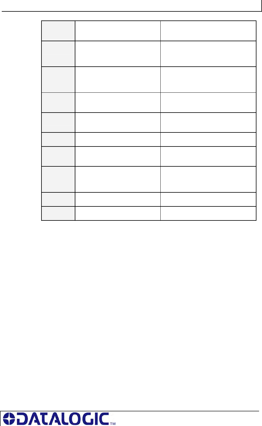
COBALT UHF-SERIES CHAPTER 5: COMMAND PROTOCOLS
PAGE 88 OF 140
0x89 SUBNET RESPONSE
MALFORMED
Internal Subnet Error – a controller
returned a malformed response.
0x8A SUBNET RESPONSE TIMEOUT Internal Subnet Error – a controller was
unable to generate a response before
timeout was reached.
0x8B SUBNET RESPONSE INVALID
CHECKSUM
Internal Subnet Error – a controller
generated a response that has an
invalid checksum.
0x8C SUBNET DEVICE CONFLICT
DETECTED
Internal Subnet Error – a Node ID
conflict has been detected
0x8D BUFFER OVERFLOW Internal Error – buffer limit was
exceeded
0x8E FLASH FAILURE Internal Error – flash memory failure
0x92 SUBNET16 ONLY COMMAND A Subnet16-only command was issued
when in MUX32 mode.
0x93 NODE MISMATCH ERROR The Node specified in the command
did not match the Node to which the
command was sent
0x94 CRC ERROR Internal Communications Error
0x95 PROTOCOL ERROR Internal Communications Error
Table 5-19: Error Code Table
COBALT UHF-SERIES CHAPTER 6: ETHERNET/IP INTERFACE
PAGE 89 OF 140
CHAPTER 6:
ETHERNET/IP INTERFACE
The Cobalt UHF-CNTL-IND-02 model is designed to support many common
Industrial Ethernet protocols and can be implemented in a wide variety of existing
host / PLC applications. One such popular Ethernet protocol is Ethernet/IP (EIP).
This chapter focuses on the process of setting up the Cobalt Industrial RFID
Controller to communicate (via Ethernet/IP) with a ControlLogix Programmable Logic
Controller (PLC).
Also in this chapter are descriptions of EMS’ HTML Server and OnDemand Utilities,
as well as systematic instructions to help configure the Cobalt Industrial RFID
Controller for Ethernet/IP environments.
NOTE: This manual assumes that users are already familiar with Ethernet/IP, industrial
Ethernet communications protocols and programmable logic controller technologies.
For specific information regarding the protocol used by your particular RFID application,
please refer to the appropriate documentation from your host / PLC program provider.
IMPORTANT:
Users of the Cobalt Dashboard utility should exit the application before attempting
communications between the Industrial Cobalt and an EtherNet/IP host
Programmable Logic Controller (PLC).
When installing the UHF-CNTL-IND-02 for communication over EtherNet/IP, the
ODVA Guidelines for EtherNet/IP Media System installation should be followed (refer
to www.odva.org, ODVA PUB00148R0 (Pub 148), EtherNet/IP Media Planning and
Installation Manual, 2006 ODVA).
Follow ODVA recommendations for switching and wiring Ethernet/IP.
If the Ethernet/IP network enables I/O Messaging for remote I/O, etc., or if other UDP
traffic is present, then the Gateway must be protected by a switch that incorporates
IGMP Snooping or a VLAN.
6.1 ETHERNET/IP CONFIGURATION OVERVIEW
Based upon on the standard TCP/IP protocol suite, EtherNet/IP is a high-level
application layer protocol for industrial automation applications that uses traditional
Ethernet hardware and software to define an application layer protocol that structures
the task of configuring, accessing and controlling industrial automation devices.
Ethernet/IP classifies Ethernet nodes as predefined device types with specific
behaviors. The set of device types and the EIP application layer protocol is based on
the Common Industrial Protocol (CIP) layer used in ControlNet. Building on these two
widely used protocol suites, Ethernet/IP provides a seamlessly integrated system
from the RFID Subnet network to the Host and enterprise networks.
The Cobalt is designed to communicate as an EtherNet/IP client device, which will
receive and execute RFID commands issued by the host / PLC (acting as
EtherNet/IP Server).
COBALT UHF-SERIES CHAPTER 6: ETHERNET/IP INTERFACE
PAGE 90 OF 140
Sections 6.3 through 6.7 contain instructions that will help you accomplish the
following:
Assign the Cobalt an IP address via HTML Server
Configure the Cobalt’s Subnet Node via OnDemand Utilities
Create “Controller Tags” in the PLC
Verify PLC and Cobalt Subnet Node connectivity
6.2 HTML SERVER & ONDEMAND PLC SUPPORT
Below is a partial list of the programmable logic controllers that are supported by
EMS’ HTML Server and OnDemand Utilities.
ControlLogix – OnDemand supports all current versions
RA’s PLC5E releases:
Series C, Revision N.1
Series D, Revision E.1
Series E, Revision D.1
PLC5 "Sidecar" Module Series B, Revision A with EIP support
SLC5/05 releases:
Series A with firmware revision OS501, FRN5
All Series B and Series C PLC Controllers
6.3 HTML SERVER AND ONDEMAND UTILITIES
Embedded in the Cobalt UHF-CNTL-IND-02 is an HTML Server, which provides a
Website-like interface and a suite of configuration tools.
Through the use of the Cobalt’s HTML Server, users can access, modify and save
changes to the unit’s Industrial Ethernet configuration, IP address, and OnDemand
mode settings.
The OnDemand Utilities will be used later in this chapter to link the Cobalt to specific
Controller Tags as defined in Rockwell Automation’s (RA) ControlLogix PLC.
ATTENTION: Disable any firewall services affecting or running locally on the host
computer. Firewalls can potentially block communications between the Cobalt and the
host and/or PLC.
ADDITIONAL INFORMATION: In ControlLogix, a “Controller Tag” is a small block of
internal memory that is used to hold outgoing (command) and incoming (response)
data. Within each controller tag, information is stored in two-byte segments, known as
registers or “words.”
OnDemand is Escort Memory Systems’ approach to adding Change of State
messaging to ControlLogix and legacy support for RA PLC5E and RA SCL5/05
programmable logic controllers.
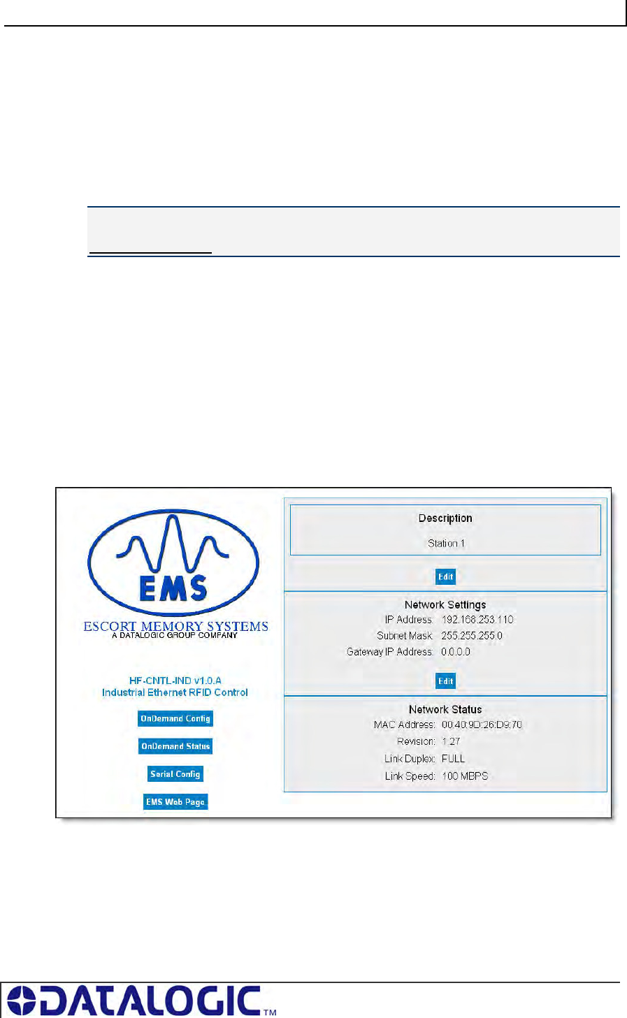
COBALT UHF-SERIES CHAPTER 6: ETHERNET/IP INTERFACE
PAGE 91 OF 140
6.4 IP CONFIGURATION VIA
HTML
S
ERVER
To configure the Cobalt for Ethernet communications, begin by assigning the
controller a locally compatible IP address.
Through a standard Web browser, you can utilize the Cobalt’s HTML Server to
access an embedded suite of controller configuration tools, called the “OnDemand
Utilities.” Among its features is the ability to modify and save changes to the
controller’s IP address, which is stored internally on the Cobalt.
Cobalt Industrial Ethernet RFID Controller - Default IP Address:
192.168.253.110
SETTING THE IP ADDRESS OF THE COBALT
To set the Cobalt’s IP address using the HTML Server, follow the steps below:
1. Open a Web browser on the PC.
2. In the URL address field, enter the Cobalt’s IP address (192.168.253.110 =
factory default).
3. Press ENTER.
The HTML Server - Main Page will be displayed.
HTML SERVER – MAIN PAGE
Figure 6-1: The HTML Server - Main Page
The HTML Server - Main Page lists the IP address and network settings currently
stored on the Cobalt.
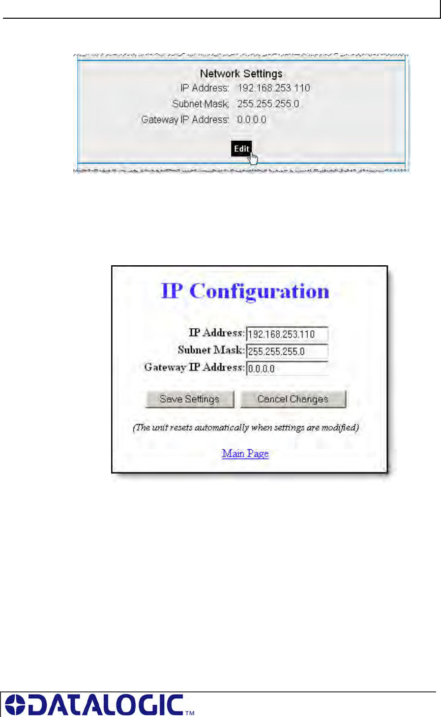
COBALT UHF-SERIES CHAPTER 6: ETHERNET/IP INTERFACE
PAGE 92 OF 140
4. Click the button labeled “EDIT”, located below “Network Settings.”
The IP Configuration Page will be displayed.
IP CONFIGURATION PAGE
The IP Configuration Page is used to modify and save changes to the IP Address,
Subnet Mask and (Network) Gateway IP Address.
Figure 6-2: The IP Configuration Page
5. In the fields provided, enter your new IP configuration values for the Cobalt.
6. Click the “Save Settings” button to store your new IP configuration, then
cycle power to the UHF-CNTL to store the changes in the main memory. The
Ethernet module will reset and your IP changes will be implemented.
7. After the Cobalt has restarted, verify the new IP configuration by opening a
Web browser and manually entering the Cobalt’s new IP address in the URL
field. If successful, you should arrive back at the HTML Server – Main Page.
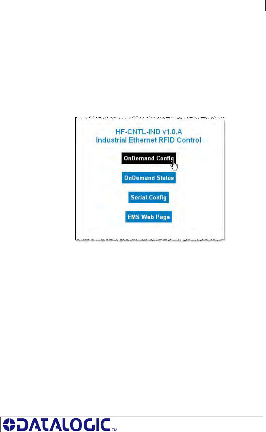
COBALT UHF-SERIES CHAPTER 6: ETHERNET/IP INTERFACE
PAGE 93 OF 140
6.5 ONDEMAND CONFIGURATION FOR ETHERNET/IP
Now that you have configured the Cobalt’s IP address, you will need to use the
embedded HTML Server to access the Cobalt’s OnDemand Configuration Page.
Through the use of the OnDemand Configuration Page, the Cobalt can be configured
to communicate with a ControlLogix PLC.
To configure the Cobalt’s OnDemand Configuration settings, follow the steps below:
1. Open a Web browser on the host and enter the Cobalt’s new IP address in the
URL field. The HTML Server – Main Page will be displayed.
2. At the HTML Server – Main Page, click the button labeled “OnDemand Config.”
The OnDemand Configuration Page will be displayed.
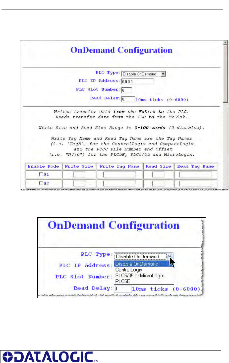
COBALT UHF-SERIES CHAPTER 6: ETHERNET/IP INTERFACE
PAGE 94 OF 140
ONDEMAND CONFIGURATION PAGE
The OnDemand Configuration Page allows you to modify the settings of the
Cobalt’s Node.
Figure 6-3: The OnDemand Configuration Page
3. In the upper portion of the OnDemand Configuration Page, select a PLC Type
from the drop-down menu.
4. Enter the PLC’s IP address.
5. For the PLC Slot Number, enter a value between 0 and 255. The PLC Slot
Number indicates the location in your PLC rack where the controller module is
installed (normally slot 0 for ControlLogix).
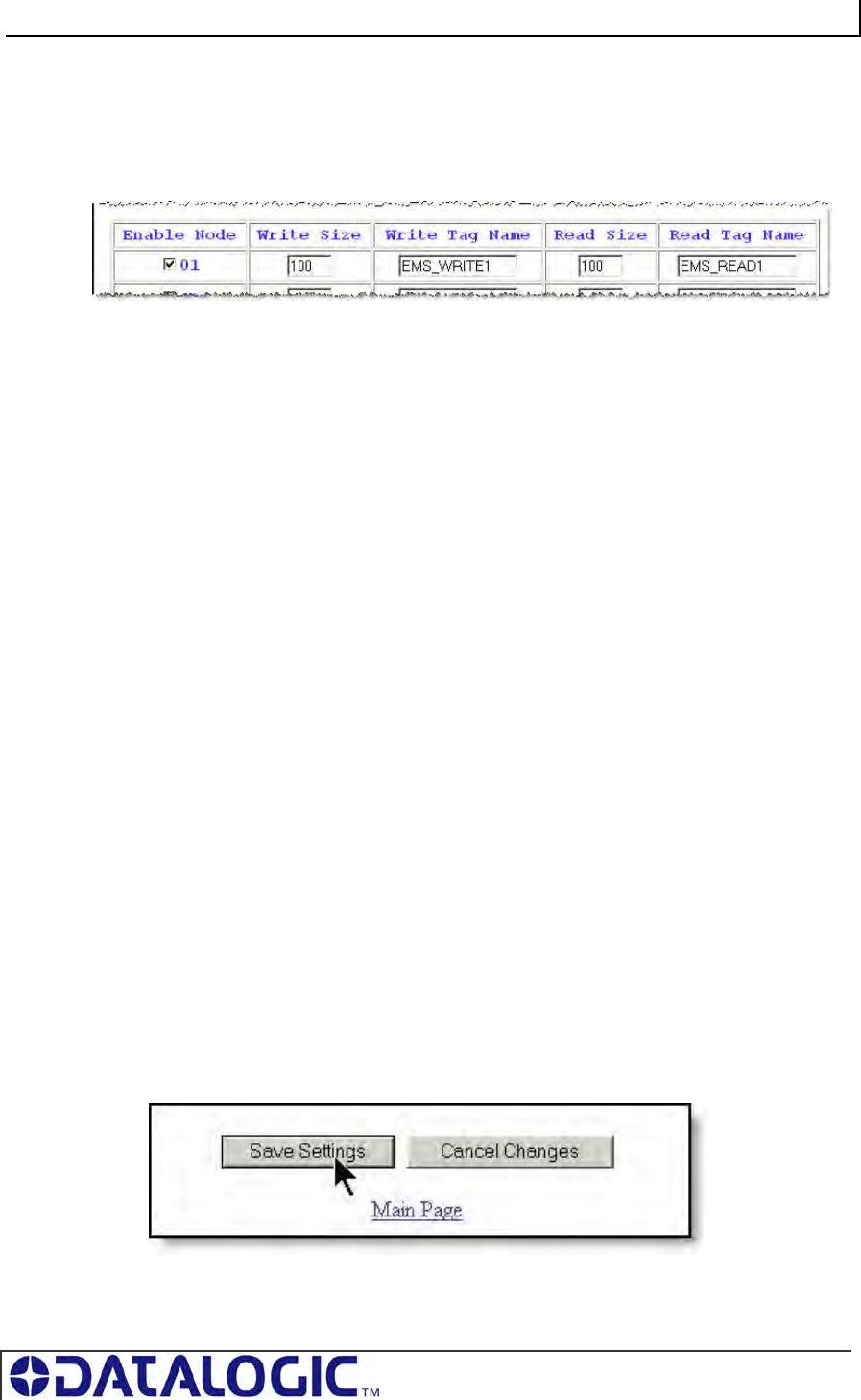
COBALT UHF-SERIES CHAPTER 6: ETHERNET/IP INTERFACE
PAGE 95 OF 140
6. In the Read Delay field, enter a value between 0 and 6000. This number
specifies (in 10ms “ticks”) how frequently the Cobalt will poll the PLC for the
presence of new data. (Note: a value of 6000 = 60 seconds; zero = disable).
7. In the column labeled “Enable Node,” place a check in the box for Node 01.
Other Nodes listed on this page are not supported by the Cobalt –IND.
8. Write Size:
Enter a value between 1 and 100 (or 0 to disable) for the Write Size.
The Write Size represents the maximum number of 2-byte “words” that the
Cobalt will attempt to write to PLC memory during a single write cycle. (Note: to
accommodate message handshaking overhead, the actual data size required by
the PLC is three words larger than the value specified in this field).
9. Write Tag Name: For ControlLogix systems, specify a Write Tag Name that is
40 characters or less (for example EMS_WRITE1, for Node 01). The Write Tag
Name is a user defined description or title for the area of memory in the PLC
where host-bound data will be written for the Cobalt. (Note: the Write Tag Name
is not to be confused with writing to an RFID transponder, which is often referred
to as “writing to a tag”).
OR
Write Tag Name: For PLC5E, SLC5/05 and MicroLogix systems, enter the PCCC
File Number and Offset (for example N7:0) in the Write Tag Name field. Together
these values identify the location in the PLC’s Status File where host-bound data will
be written for the Cobalt.
10. Read Size: Enter a value between 1 and 100 (or 0 to disable) for the Read Size.
The Read Size represents the maximum number of 2-byte “words” that the
Cobalt will attempt to retrieve from PLC memory during a single read cycle.
(Note: to accommodate message handshaking overhead, the actual data size
required by the PLC is three words larger than the value specified in this field).
11. Read Tag Name: For ControlLogix systems, specify a Read Tag Name that is
40 characters or less (for example EMS_READ1, for Node 01). The Read Tag
Name is a user defined description or title for the area of memory in the PLC
from which the Cobalt will retrieve data.
OR
Read Tag Name: For PLC5E, SLC5/05 and MicroLogix systems enter the
PCCC File Number and Offset in the Read Tag Name field. Together these
values indicate the location in the PLC’s Status File from which the Cobalt
will retrieve data.
12. After entering the proper information for Node 01, click the Save Settings button
located at the bottom of the page.
The OnDemand Status Page will be displayed.
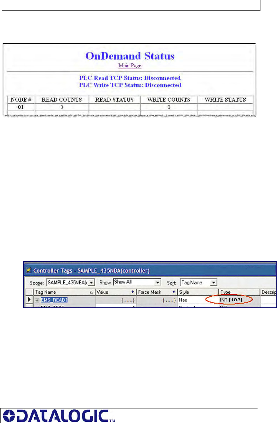
COBALT UHF-SERIES CHAPTER 6: ETHERNET/IP INTERFACE
PAGE 96 OF 140
13. At the OnDemand Status Page, click the link labeled “Main Page” to return to the
HTML Server – Main Page.
6.6 CONFIGURING PLC CONTROLLER TAGS
After you have configured the Cobalt’s Node via the OnDemand Configuration Page,
open your PLC program (i.e. RSLogix 5000) and, if you have not already done so,
define two Controller Tags (a Write Tag and a Read Tag).
Controller Tag Naming
Controller Tags need to be assigned a name and size. Be sure to use the same
Write Tag Name and Read Tag Name that you specified in the OnDemand Node
Configuration (i.e., EMS_WRITE1 and EMS_READ1).
Controller Tag Size
Due to handshaking overhead, Controller Tags must have the size capacity to store
an integer array equal to your previously specified Write/Read Size + three words.
So for example, if the Read Size you specified earlier was 100 words, the
corresponding Read Tag in the PLC must be able to store an array of 103 integers.
The Write Tag holds messages and response data generated by the Cobalt that
is bound for the host or PLC.
The Read Tag holds RFID commands and instructions intended for the Cobalt.
(NOTE: the Cobalt should already be linked to the proper Write Tag and Read Tag
via the OnDemand Utilities - OnDemand Configuration Page).
After creating and defining a Write Tag and a Read Tag for the Cobalt, return to the
Cobalt’s HTML Server – Main Page to continue.
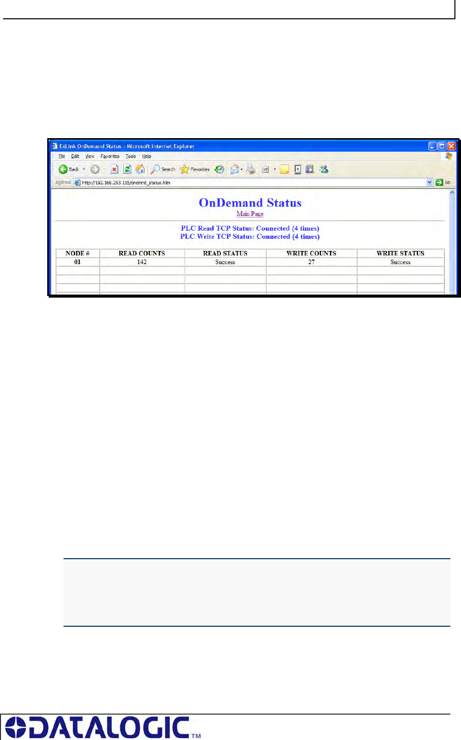
COBALT UHF-SERIES CHAPTER 6: ETHERNET/IP INTERFACE
PAGE 97 OF 140
6.7 CHECKING ONDEMAND STATUS
Now that you have configured the Cobalt’s Node and defined corresponding Write
and Read Tags in the PLC, the last step is to check the communication status
between the Cobalt and the PLC.
Return to the Cobalt’s HTML Server - Main Page and click the link labeled
“OnDemand Status.” The OnDemand Status Page will be displayed.
Figure 6-4: The OnDemand Status Page
The OnDemand Status Page provides statistical information regarding the connection
status of the Cobalt. This information can be used to verify that read and write
connections between the Cobalt and the PLC have been established successfully.
Read Counts: this value indicates the number of times the Cobalt has checked
the PLC for new data.
Write Counts: this value indicates the number of times the Cobalt has provided
data to the PLC.
Note that under Ethernet/IP, the host (and/or PLC) acts as the server. However,
additional messaging instructions are not required on the part of the host because
the Cobalt will automatically poll the Read Tag in the PLC at the interval specified by
the Read Delay value set via the OnDemand Configuration Utility.
There is no delay parameter when writing data to the PLC, as the Cobalt delivers all
PLC-bound data immediately after it is generated.
If you configured a low Read Delay value, the Read Counts on the OnDemand
Status Page will accumulate rapidly. This occurs because a low Read Delay value
instructs the Cobalt to poll the PLC for new data more frequently.
ATTENTION:
If the Cobalt and PLC do not successfully establish a connection, cycle power to the
Cobalt and verify that Ethernet/IP services are running properly on the PLC. If that does
not resolve the issue, restart Ethernet/IP services on the PLC and the 1756-ENBT
module.
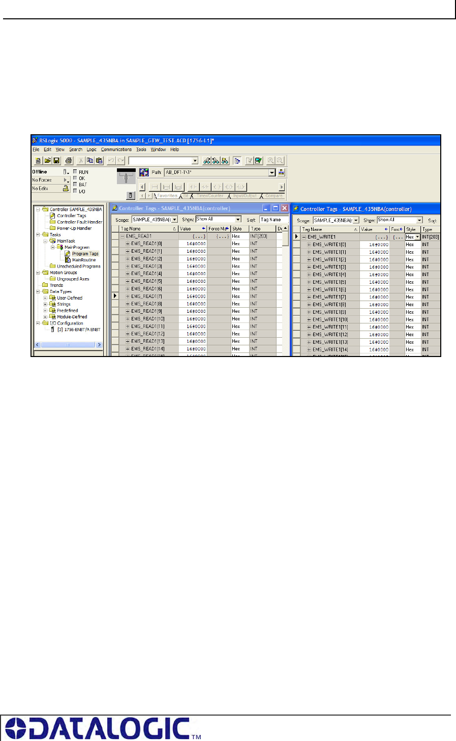
COBALT UHF-SERIES CHAPTER 6: ETHERNET/IP INTERFACE
PAGE 98 OF 140
6.8 VERIFYING DATA EXCHANGE WITH
RSLOGIX 5000
At this point, communication between the Cobalt and the PLC should be properly
configured and a connection established. You can verify the exchange of information
between devices using RSLogix 5000.
Figure 6-5: RSLogix 5000
6.8.1 Ethernet/IP Handshaking
To ensure that messages to and from the Cobalt are properly delivered and received,
a handshaking mechanism has been implemented that uses a pair of dedicated
words in the exchange. The first two words in each Controller Tag are dedicated to
handshaking.
When new information is generated, the producing device (Data Producer) will
increment a counter in one of the Controller Tags. After identifying the new data, the
consuming device (Data Consumer) will copy that same counter value to a different
Controller Tag location, which lets the Data Producer know that the information has
been processed by the Data Consumer.
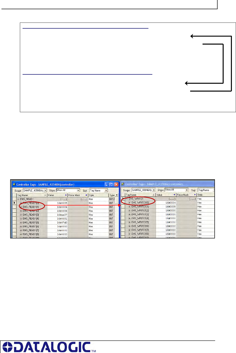
COBALT UHF-SERIES CHAPTER 6: ETHERNET/IP INTERFACE
PAGE 99 OF 140
6.8.2 Ethernet/IP Handshaking Example
In the example below, EMS_READ1 is the name of the Read Tag and EMS_WRITE1
is the name of the Write Tag.
NOTE: [0] indicates the first word, [1] indicates the second word in a controller tag.
1. The PLC writes the command to the Read Tag (EMS_READ1) and then
increments the counter in EMS_READ1 [1]
2. The counter in EMS_READ1 [1] is copied by the Cobalt to EMS_WRITE1 [0]
which acknowledges that the command has been received.
3. Following execution of the command, the Cobalt copies the response to
EMS_WRITE1 (the Write Tag) and increments the counter in EMS_WRITE1 [1].
This signals that there is new data for the PLC (the Cobalt generated response,
in this case).
WRITE TAG (where responses are written by the Cobalt)
EMS_Write1 [0] = (2) the Cobalt copies counter here to ACK
EMS_Write1 [1] = (3) the Cobalt increments this counter to signal response available
EMS_Write1 [2] = Data Size
EMS_Write1 [3-102] = Data
READ TAG (where commands are retrieved by the Cobalt)
EMS_Read1 [0] = (4) PLC copies the counter here to ACK the response
EMS_Read1 [1] = (1) PLC increments this counter after writing a command
EMS_Read1 [2] = Data Size
EMS_Read1 [3-102] = Data
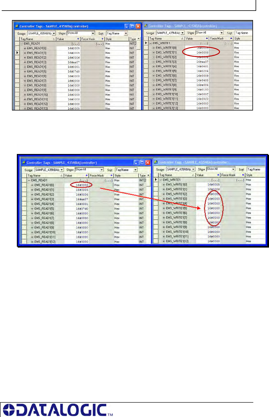
COBALT UHF-SERIES CHAPTER 6: ETHERNET/IP INTERFACE
PAGE 100 OF 140
4. After the PLC has processed the response information, it copies the counter from
EMS_WRITE1 [1] to EMS_READ1 [0] which signals to the Cobalt that the PLC
has retrieved the response data.
5. The data will then be cleared from EMS_WRITE1. After which the Cobalt will be
ready to receive another command.
6.9 ETHERNET/IP: OBJECT MODEL
The Object Model is the logical organization of attributes (parameters) within classes
(objects) and services supported by each device.
Objects are broken down into three categories: Required Objects, Vendor Specific
Objects and Application Objects.
Required Objects are classes that must be supported by all devices on
EtherNet/IP. The Cobalt has six Required Objects.
Vendor Specific Objects are classes that add attributes and services that
do not fit into the Required Objects or Application Objects categories. The
Cobalt has two Vendor Specific Objects.
Application Objects are classes that must be supported by all devices using
the same profile. An example of a profile is a Discrete I/O device or an AC
COBALT UHF-SERIES CHAPTER 6: ETHERNET/IP INTERFACE
PAGE 101 OF 140
Drive. This ensures that all devices with the same profile have a common
look on the network.
DATA TYPE DEFINITION TABLE
EtherNet/IP was designed by the Open Device Vendors Association (ODVA) as an
open protocol. The following table contains a description of the data types used by
ODVA that are also found in this chapter.
DATA TYPE DESCRIPTION
USINT Unsigned Short Integer (8-bit)
UINT Unsigned Integer (16-bit)
UDINT Unsigned Double Integer (32-bit)
STRING Character String (1 byte per character)
BYTE Bit String (8-bits)
WORD Bit String (16-bits)
DWORD Bit String (32-bits)
Table 6-1: Data Type Definitions
6.9.1 Ethernet/IP Required Objects
Under Ethernet/IP, there are six Required Objects:
REQUIRED OBJECTS:
Identity Object (0x01)
Message Router Object (0x02)
Assembly Object (0x04)
Connection Manager Object (0x06)
TCP Object (0xF5)
Ethernet Link Object (0xF6)
COBALT UHF-SERIES CHAPTER 6: ETHERNET/IP INTERFACE
PAGE 102 OF 140
IDENTITY OBJECT (0X01 - 1 INSTANCE)
Class Attributes
Attribute
ID Name / Description Data Type Default Data
Value
Access
Rule
1 Revision UINT 1 Get
Instance Attributes
Attribute
ID Name / Description Data Type Default Data
Value Access
Rule
1 Vendor Number UINT 50 DEC Get
2 Device Type UINT 0x0C Get
3 Product Code Number UINT 6102 DEC Get
4 Product Major Revision
Product Minor Revision
USINT
USINT
01
25
Get
5 Status Word (see below for
definition)
WORD See Below Get
6 Serial Number UDINT Unique
32 Bit Value
Get
7 Product Name:
Product Name Size
Product Name String
USINT
USINT[26]
HF-CNTL-
IND-02
06
“Cobalt”
Get
Status Word
Bit Bit = 0 Bit = 1
0 No I/O Connection I/O Connection Allocated
1 – 15 Unused Unused
Common Services
Implementation
Service
Code Class Level Instance Level
Service Name
0x0E Yes Yes Get Attribute Single
0x05 No Yes Reset
MESSAGE ROUTER OBJECT (0X02)
This object has no supported attributes.
COBALT UHF-SERIES CHAPTER 6: ETHERNET/IP INTERFACE
PAGE 103 OF 140
ASSEMBLY OBJECT (0X04 - 3 INSTANCES)
Class Attributes
Attribute
ID Name / Description Data
Type
Default
Data
Value
Access
Rule
1 Revision UINT 1 Get
2 Max Instance UINT 81 Get
Instance 0x64 Attributes (Input Instance)
Attribute
ID Name / Description Data
Type Default
Data
Value
Access
Rule
Status Information:
Bitmap of Consume Instances with Data DINT 0
3
Bitmap of Produce Instances with Data DINT 0
Get
User Datagram Protocol (UDP) I/O Sequence Number Handshaking
The data producing device increments the data sequence number by one with the
transmission of each new serial data packet. Valid sequence numbers are 1-65535.
After the consuming device has processed the data, it must echo the sequence
number in the handshake to allow the producing device to remove the data from the
queue. This is required for I/O communications because UDP is not guaranteed to
arrive in order.
If the Node ID number is passed as part of the I/O message, the message is stored
to the appropriate location in the Modbus RTU table. Because communications are
asynchronous, the Node ID number is also stored as part of the output data. It is the
responsibility of the PLC programmer to make sure the proper request lines up with
the proper response if the Cobalt is used as a request/response device.
Instance 0x65 Attributes (Input Instance 2)
Attribute
ID
Name / Description Data Type Default Data
Value
Access
Rule
Serial Produce Data:
Consume Data Seq. Number
Handshake
UINT 0
Produce Data Sequence
Number
UINT 0
Node 1 Serial Produce Data
Size
UINT 0
3
Node 1 Serial Produce Data WORD[100] All 0’s
Get
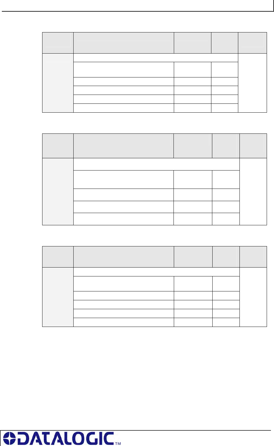
COBALT UHF-SERIES CHAPTER 6: ETHERNET/IP INTERFACE
PAGE 104 OF 140
Instance 0x66 Attributes (Input Instance 3)
Attribute
ID Name / Description Data Type Default
Data
Value
Access
Rule
Serial Produce Data:
Consume Data Seq. Number
Handshake
UINT 0
Produce Data Sequence Number UINT 0
Node ID (1-32) UINT 1
Node Serial Produce Data Size UINT 0
3
Node Serial Produce Data WORD[100] All 0’s
Get
Instance 0x70 Attributes (Output Instance 1)
Attribute
ID
Name / Description Data Type Default
Data
Value
Access
Rule
Serial Consume Data:
Produce Data Seq. Number
Handshake
UINT 0
Consume Data Sequence Number UINT 0
Node 1 Serial Consume Data Size UINT 0
3
Node 1 Serial Consume Data WORD[100] All 0’s
Get /
Set
Instance 0x71 Attributes (Output Instance 2)
Attribute
ID Name / Description Data Type Default
Data
Value
Access
Rule
Serial Consume Data:
Produce Data Seq. Number
Handshake
UINT 0
Consume Data Sequence Number UINT 0
Node ID (1-32) UINT 1
Node Serial Consume Data Size UINT 0
3
Node Serial Consume Data WORD[100] All 0’s
Get /
Set
Instance 0x80 Attributes (Configuration Instance)
Most I/O clients include a configuration path when opening an I/O connection to a
server. There is no configuration data needed.
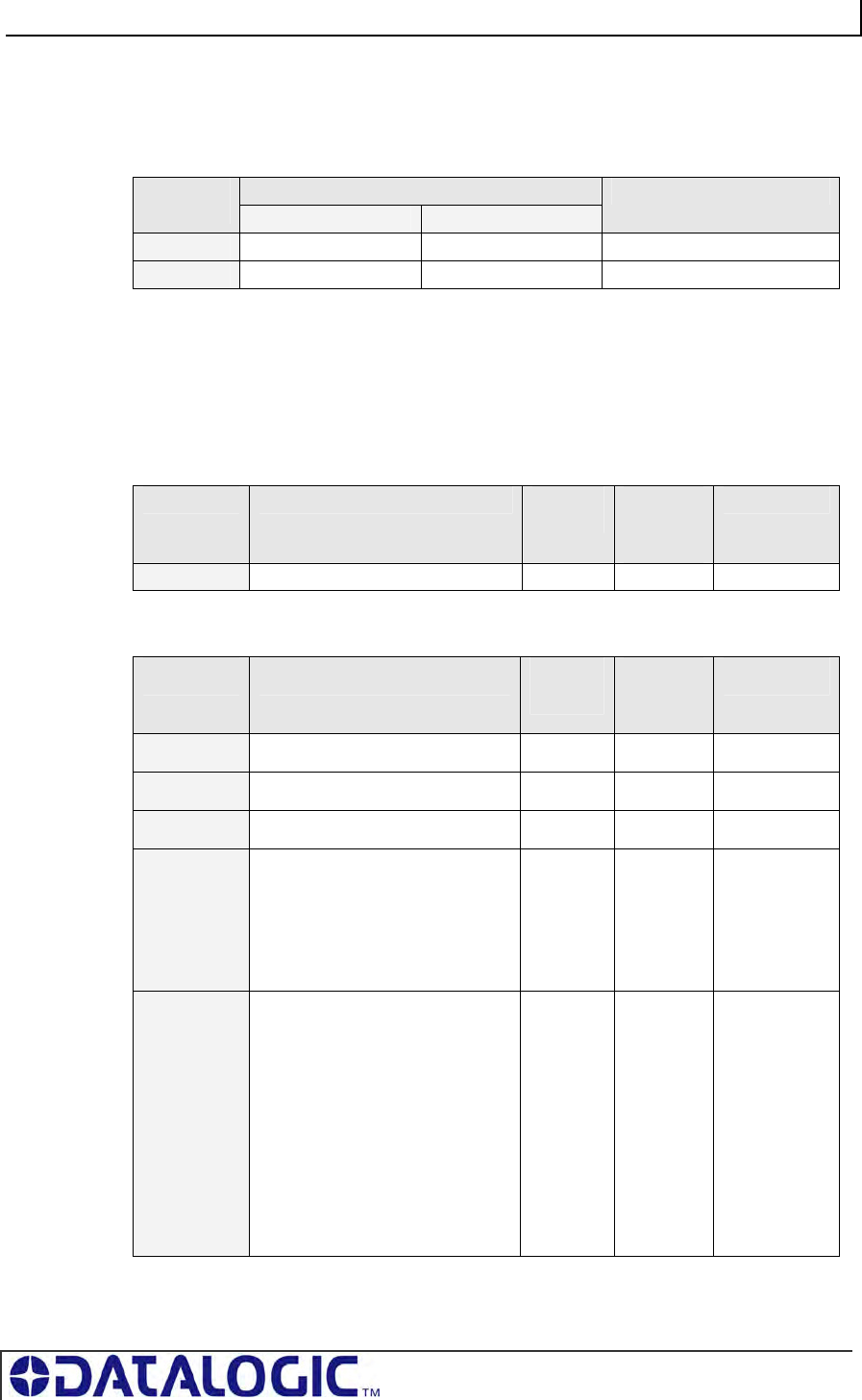
COBALT UHF-SERIES CHAPTER 6: ETHERNET/IP INTERFACE
PAGE 105 OF 140
Instance 0x81 Attributes (Heartbeat Instance – Input Only)
This instance allows clients to monitor input data without providing output data.
Common Services
Implementation
Service
Code Class Level Instance Level
Service Name
0x0E Yes Yes Get Attribute Single
0x10 No Yes Set Attribute Single
CONNECTION MANAGER OBJECT (0X06)
This object has no attributes.
TCP OBJECT (0XF5 - 1 INSTANCE)
Class Attributes
Attribute ID Name / Description Data
Type Default
Data
Value
Access Rule
1 Revision UINT 1 Get
Instance Attributes
Attribute ID Name / Description Data
Type
Default
Data
Value
Access Rule
1 Status* DWORD 1 Get
2 Configuration Capability* DWORD 0 Get
3 Configuration Control* DWORD 0 Get
4 Physical Link Object*
Structure of:
Path Size
Path
UINT
Array Of
WORD
2
0x20F6
0x2401
Get
5 Interface Configuration*
Structure of:
IP Address
Network Mask
Gateway Address
Name Server
Name Server 2
Domain Name Size
Domain Name
UDINT
UDINT
UDINT
UDINT
UDINT
UINT
STRING
0
0
0
0
0
0
0
Get
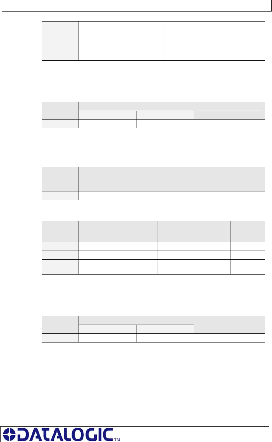
COBALT UHF-SERIES CHAPTER 6: ETHERNET/IP INTERFACE
PAGE 106 OF 140
6 Host Name*
Structure of:
Host Name Size
Host Name
UINT
STRING
0
0
Get
*See section 5-3.2.2.1 – 5-3.2.2.6 of “Volume 2: EtherNet/IP Adaptation of CIP” from
ODVA for more information regarding these attributes.
Common Services
Implementation
Service
Code Class Level Instance Level
Service Name
0x0E Yes Yes Get Attribute Single
ETHERNET LINK OBJECT (0XF6 - 1 INSTANCE)
Class Attributes
Attribute ID Name / Description Data Type Default
Data
Value
Access
Rule
1 Revision UINT 1 Get
Instance Attributes
Attribute ID Name / Description Data Type Default
Data
Value
Access
Rule
1 Interface Speed* UDINT 100 Get
2 Interface Flags* DWORD 3 Get
3 Physical Address* USINT
Array[6]
0 Get
*See section 5-4.2.2.1 – 5-4.2.2.3 of “Volume 2: EtherNet/IP Adaptation of CIP” from
ODVA for more details on this attribute.
Common Services
Implementation
Service
Code Class Level Instance Level
Service Name
0x0E Yes Yes Get Attribute Single
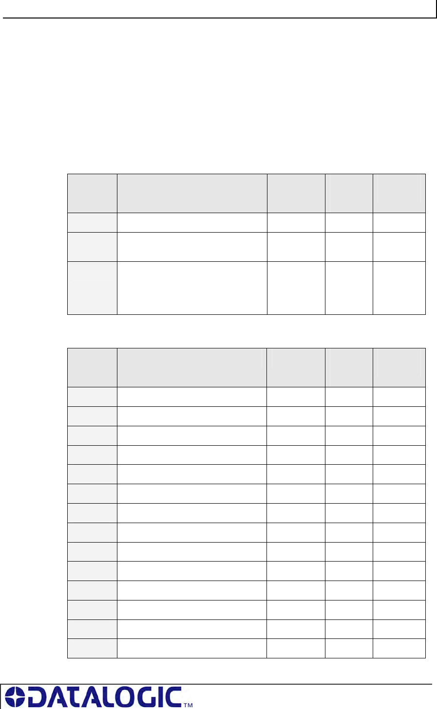
COBALT UHF-SERIES CHAPTER 6: ETHERNET/IP INTERFACE
PAGE 107 OF 140
6.9.2 EtherNet/IP: Vendor Specific Objects
The Cobalt has two Vendor Specific Objects:
VENDOR SPECIFIC OBJECTS:
Cobalt Consume Data Object (0x64)
Cobalt Produce Data Object (0x65)
COBALT CONSUME DATA OBJECT (0X64 - 32 INSTANCES)
Class Attributes (Instance 0)
Attribute
ID Name / Description Data Type Default
Data
Value
Access
Rule
1 Revision UINT 1 Get
2 Maximum Consume Data Buffer
Size (in words)
UINT 32768 Get
3 Bitmap of Consume Instances with
Data
Bit 0: Instance 1 … Bit 31: Instance
32
DINT 0 Get
Instance Attributes (Instances 1-32)
Attribute
ID
Name / Description Data Type Default
Data
Value
Access
Rule
1 Consume Data Size (in words) UINT 0 Get / Set
2 Consume Data [0-249] UINT 0 Get / Set
3 Consume Data [250-499] UINT 0 Get / Set
4 Consume Data [500-749] UINT 0 Get / Set
5 Consume Data [750-999] UINT 0 Get / Set
6 Consume Data [1,000-1,249] UINT 0 Get / Set
… … … … …
10 Consume Data [2,000-2,249] UINT 0 Get / Set
… … … … …
34 Consume Data [8,000-8,249] UINT 0 Get / Set
… … … … …
38 Consume Data [9,000-9,249] UINT 0 Get / Set
… … … … …
42 Consume Data [10,000-10,249] UINT 0 Get / Set
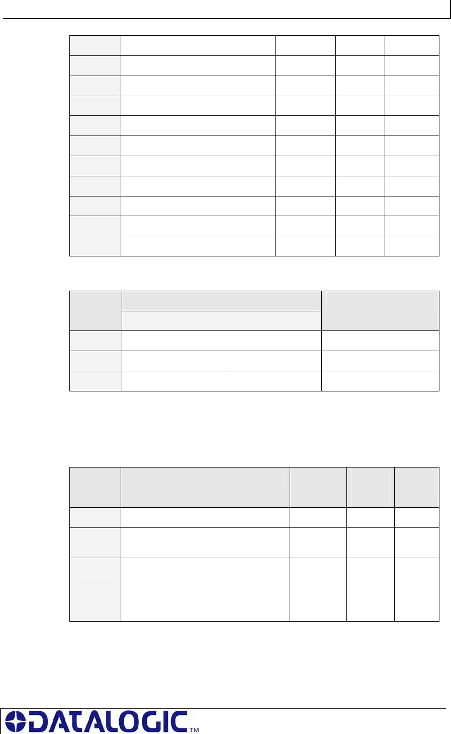
COBALT UHF-SERIES CHAPTER 6: ETHERNET/IP INTERFACE
PAGE 108 OF 140
… … … … …
82 Consume Data [20,000-20,249] UINT 0 Get / Set
… … … … …
122 Consume Data [30,000-30,249] UINT 0 Get / Set
… … … … …
126 Consume Data [31,000-31,249] UINT 0 Get / Set
… … … … …
130 Consume Data [32,000-32,249] UINT 0 Get / Set
131 Consume Data [32,250-32,249] UINT 0 Get / Set
132 Consume Data [32,500-32,249] UINT 0 Get / Set
133 Consume Data [32,750-32,767] UINT 0 Get / Set
Common Services
Implementation Service
Code Class Level Instance Level
Service Name
0x05 No Yes Reset*
0x0E Yes Yes Get Attribute Single
0x10 No Yes Set Attribute Single
*This Service Code is used to flush all attributes to zero.
COBALT PRODUCE DATA OBJECT (0X65 - 32 INSTANCES)
Class Attributes (Instance 0)
Attribute
ID Name / Description Data Type Default
Data
Value
Access
Rule
1 Revision UINT 1 Get
2 Maximum Produce Data Buffer Size (in
words)
UINT 32768 Get
3 Bitmap of Produce Instances with Data
Bit 0: Instance 1 … Bit 31: Instance 32
DINT 0 Get
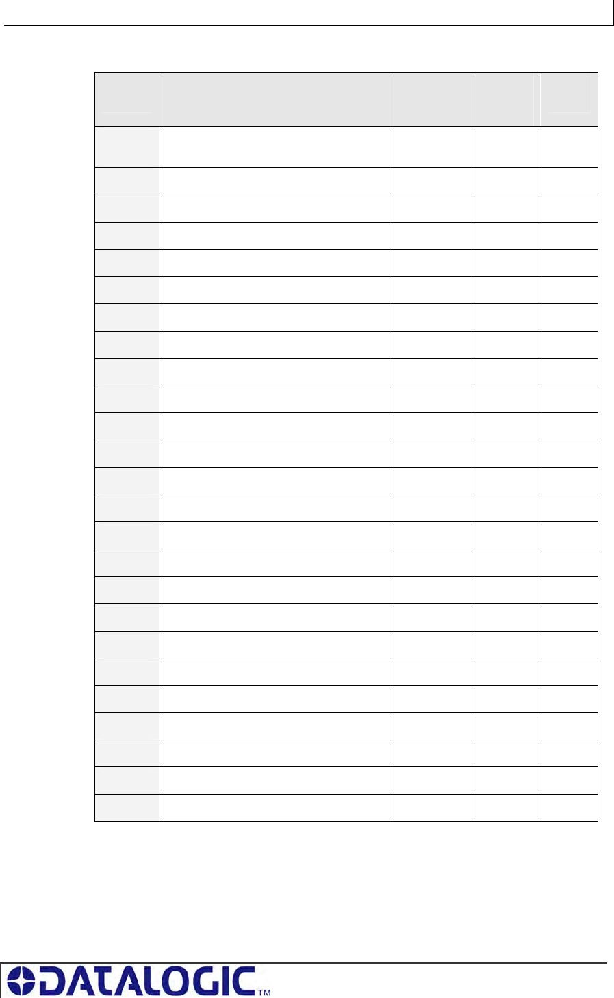
COBALT UHF-SERIES CHAPTER 6: ETHERNET/IP INTERFACE
PAGE 109 OF 140
Instance Attributes (Instances 1-32)
Attribute
ID
Name / Description Data Type Default
Data
Value
Access
Rule
1 Produce Data Size (in words) UINT 0 Get /
Set
2 Produce Data [0-249] UINT 0 Get
3 Produce Data [250-499] UINT 0 Get
4 Produce Data [500-749] UINT 0 Get
5 Produce Data [750-999] UINT 0 Get
6 Produce Data [1,000-1,249] UINT 0 Get
… … … … …
10 Produce Data [2,000-2,249] UINT 0 Get
… … … … …
34 Produce Data [8,000-8,249] UINT 0 Get
… … … … …
38 Produce Data [9,000-9,249] UINT 0 Get
… … … … …
42 Produce Data [10,000-10,249] UINT 0 Get
… … … … …
82 Produce Data [20,000-20,249] UINT 0 Get
… … … … …
122 Produce Data [30,000-30,249] UINT 0 Get
… … … … …
126 Produce Data [31,000-31,249] UINT 0 Get
… … … … …
130 Produce Data [32,000-32,249] UINT 0 Get
131 Produce Data [32,250-32,249] UINT 0 Get
132 Produce Data [32,500-32,249] UINT 0 Get
133 Produce Data [32,750-32,767] UINT 0 Get
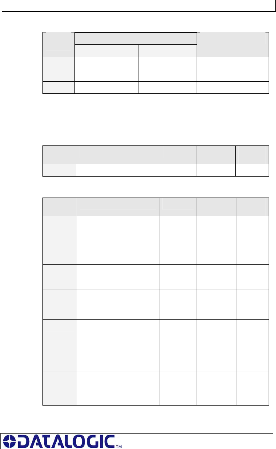
COBALT UHF-SERIES CHAPTER 6: ETHERNET/IP INTERFACE
PAGE 110 OF 140
Common Services
Implementation Service
Code Class Level Instance Level
Service Name
0x05 No Yes Reset*
0x0E Yes Yes Get Attribute Single
0x10 No Yes Set Attribute Single
*This Service Code is used to flush all attributes to zero.
6.9.3 Application Object (0x67 – 10 Instances)
Class Attributes (Instance 0)
Attribute
ID Name / Description Data Type Default Data
Value Access
Rule
1 Revision UINT 1 Get
Instance Attributes (Instances 1-32)
Attribute
ID Name / Description Data Type Default Data
Value Access
Rule
1 Instance Type (0-3):
0 - Disable
1 – ControlLogix
2 – SLC 5/05
3 – PLC5E
USINT 0 Get
2 PLC IP Address UDINT 0 Get
3 PLC Slot Location (0-255) USINT 0 Get
11 Max Write Size in Words:
0 – Disabled
1 – 100 Words
UINT 0 Get
12 Write Tag Name (ControlLogix
Only)
SHORT
STRING
0 Get
13 Write File Number (SLC/PLC
Only)
NX:0 - where “X” is the File
Number
UINT 7 Get
14 Write File Offset (SLC/PLC
Only)
N7:Y - where “Y” is the File
Offset
UINT 0 Get
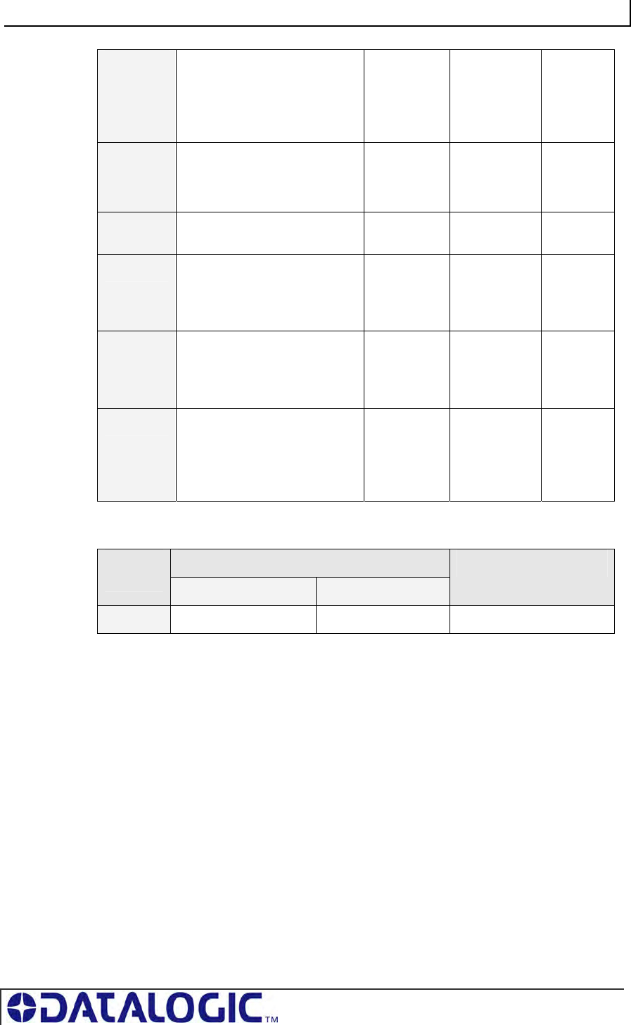
COBALT UHF-SERIES CHAPTER 6: ETHERNET/IP INTERFACE
PAGE 111 OF 140
15 Write “Heartbeat” Timeout
Measured in 10ms “ticks”
0 = disabled
Max value: 6000 ticks
UINT 100 Get
21 Max Read Size in Words
0 – Disable
Max Value: 100
UINT 0 Get
22 Read Tag Name (ControlLogix
Only)
SHORT
STRING
0 Get
23 Read File Number (SLC/PLC
Only)
NX:0 - Where “X” is the File
Number
UINT 7 Get
24 Read File Offset (SLC/PLC
Only)
N7:Y - Where “Y” is the File
Offset
UINT 0 Get
25 Read Poll Rate
Measured in 10ms “ticks”
0 = disabled
6000 ticks max
UINT 100 Get
Common Services
Implementation Service
Code Class Level Instance Level
Service Name
0x0E Yes Yes Get Attribute Single
COBALT UHF-SERIES CHAPTER 7: MODBUS TCP INTERFACE
PAGE 112 OF 140
CHAPTER 7:
MODBUS TCP INTERFACE
One of the most popular and well-proven industrial automation protocols in use today
is Modbus®. Modbus is an open client/server application protocol. Modbus TCP
allows the Modbus protocol to be carried over standard Ethernet networks. Modbus
TCP is managed by the Modbus-IDA User Organization.
7.1 MODBUS TCP OVERVIEW
Under the MODBUS® TCP protocol, the Cobalt acts as a Modbus Server and the
PLC acts as a Modbus Client. By utilizing Produce and Consume registers for
mapping commands and responses, data produced by the Cobalt is consumed by
the Modbus Client and data produced by the Modbus Client is consumed by the
Cobalt.
ATTENTION:
• Modbus Client (Host or PLC) must connect to the Modbus Server (Cobalt) on port
50200
• Maximum number of words transferred to/from an RFID tag per read/write cycle: 100
Words / 200 Bytes
• Disable any firewall services running on the PC. Firewalls can potentially block
communications between the Cobalt and the host and/or PLC
7.2 MODBUS TCP CONFIGURATION VIA
HTML
S
ERVER
To configure the Cobalt for Modbus TCP communications, begin by assigning the
controller a locally compatible IP address.
Through a standard Web browser, you can utilize the Cobalt’s HTML Server to
access an embedded suite of controller configuration tools, called the “OnDemand
Utilities.” Among its features is the ability to modify and save changes to the
controller’s IP address, which is stored internally on the Cobalt.
Cobalt Industrial Ethernet RFID Controller - Default IP Address:
192.168.253.110
7.2.1 Setting the IP Address of the Cobalt
To set the Cobalt’s IP address using the HTML Server, follow the steps below:
1. Open a Web browser on the host.
2. In the URL address field, enter the Cobalt’s IP address (192.168.253.110 =
factory default).
3. Press ENTER.
The HTML Server - Main Page will be displayed.
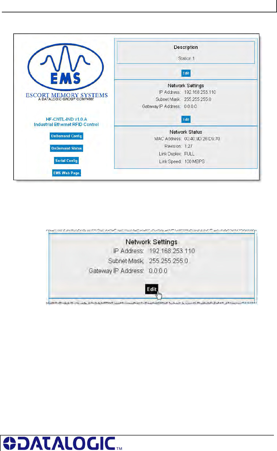
COBALT UHF-SERIES CHAPTER 7: MODBUS TCP INTERFACE
PAGE 113 OF 140
HTML SERVER – MAIN PAGE
Figure 7-1: The HTML Server - Main Page
The HTML Server - Main Page lists the network settings (including the IP address)
currently stored on the Cobalt.
4. Click the button labeled “EDIT”, located below “Network Settings.”
The IP Configuration Page will be displayed.
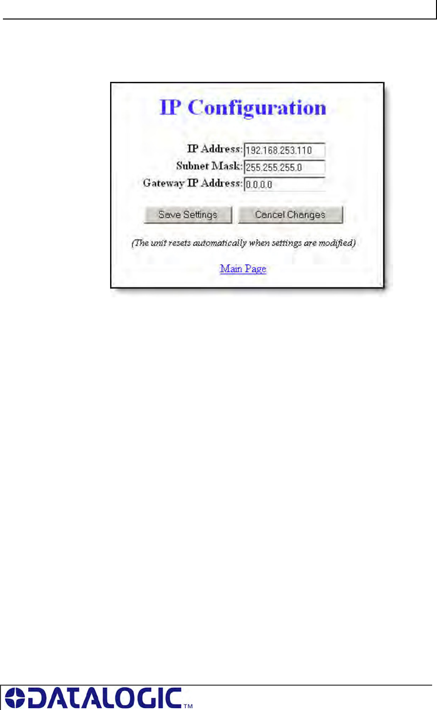
COBALT UHF-SERIES CHAPTER 7: MODBUS TCP INTERFACE
PAGE 114 OF 140
IP CONFIGURATION PAGE
The IP Configuration Page is used to modify and save changes to the IP Address,
Subnet Mask and (Network) Gateway IP Address.
Figure 7-2: The IP Configuration Page
5. In the fields provided, enter your new IP configuration values for the Cobalt.
6. Click the “Save Settings” button to store your new IP configuration, then cycle
power to the UHF-CNTL to store the changes in the main memory. The Ethernet
module will reset and your IP changes will be implemented.
7. After the Cobalt has restarted, verify the new IP configuration by opening a Web
browser and manually entering the Cobalt’s new IP address in the URL field. If
successful, you should arrive back at the HTML Server – Main Page.
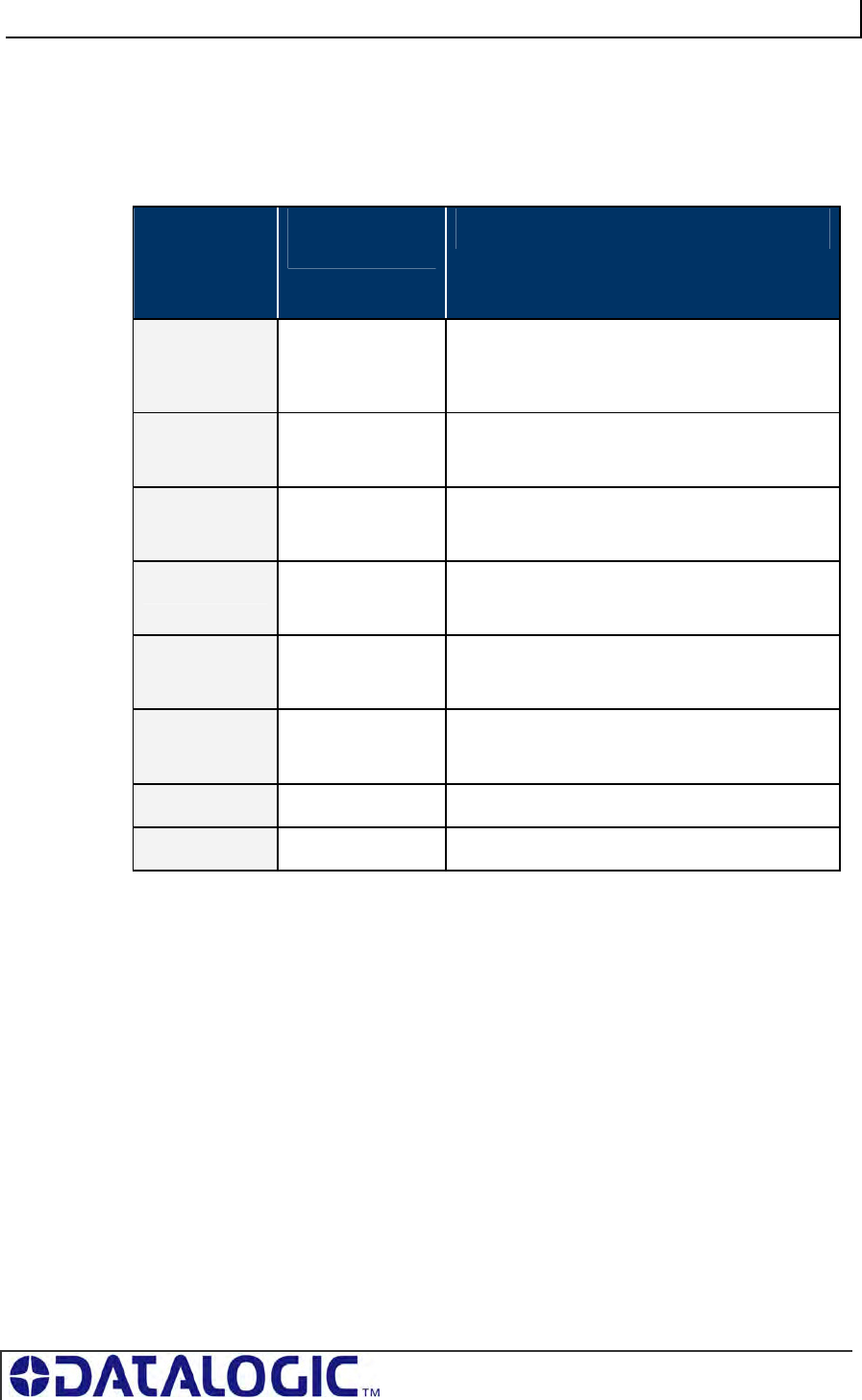
COBALT UHF-SERIES CHAPTER 7: MODBUS TCP INTERFACE
PAGE 115 OF 140
7.2.2 Modbus TCP - Command Packet Structure
Consume Registers hold data that is destined for the Cobalt. Modbus TCP
commands must be placed in the holding registers, starting at address 40001, of
Device ID 01 (Node Input Page 01). Commands utilize at least six registers (double-
byte values or words).
MODBUS
ADDRESS
(4XXXX /
3XXXX)
READ / WRITE
PRIVILEGE
REGISTER DESCRIPTION
(40001) 1 R/W 2-byte Consume Data Overall Length
(> 0 indicates data is available; Cobalt clears to 0
after data is processed)
2 R/W MSB = Reader Type
LSB = Command ID
3 R/W MSB = 0x00
LSB = Node ID (0x01 for the Cobalt)
4 R/W 2-byte Timeout Value
(0-65535) measured in milliseconds
5 R/W 2-byte Start Address
(0-65535)
6 R/W 2-byte Read/Block Size
(0-65535 bytes)
7 – 32774 R/W Cobalt Consume Data (when applicable)
32775 – 65536 R/W Reserved
Table 7-1: Modbus TCP - Command Packet Structure
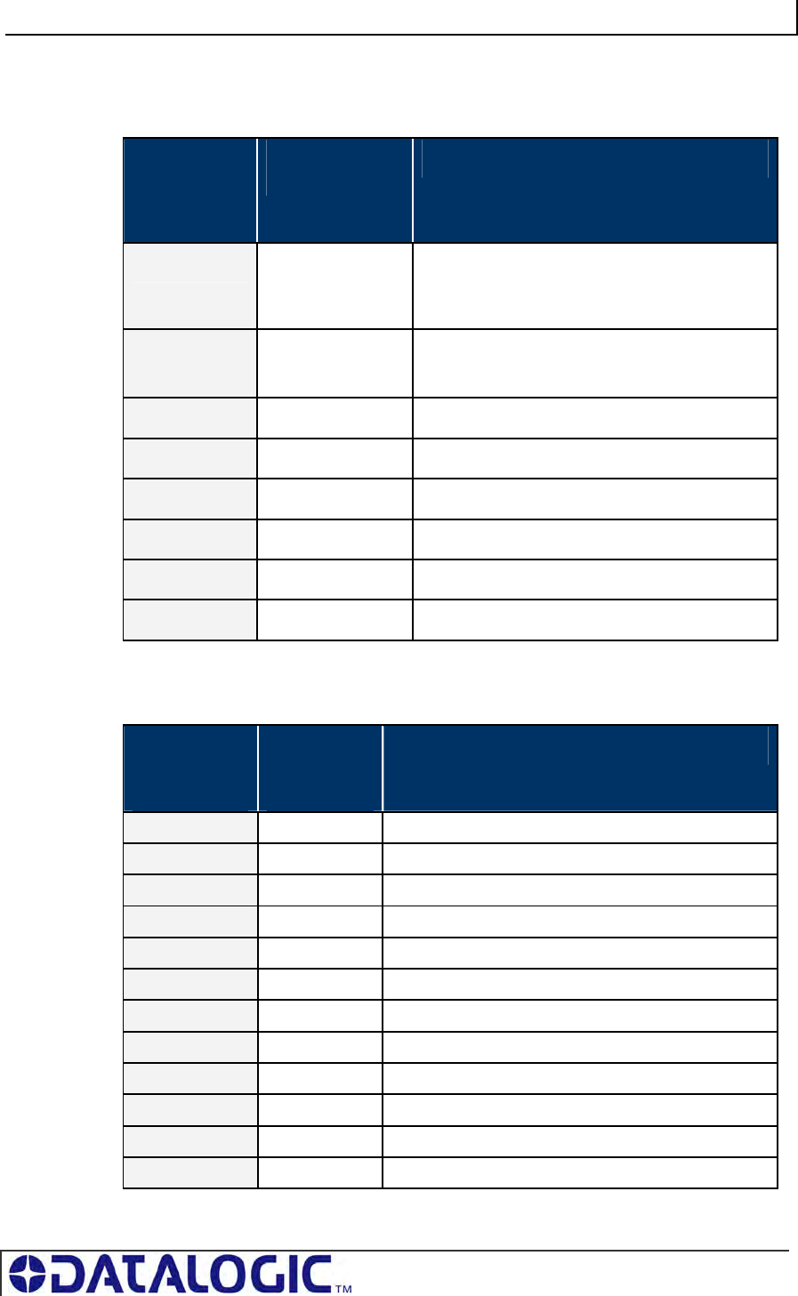
COBALT UHF-SERIES CHAPTER 7: MODBUS TCP INTERFACE
PAGE 116 OF 140
7.2.3 Modbus TCP - Response Packet Structure
Produce Registers hold data that is destined for the host or PLC.
MODBUS
ADDRESS
(4XXXX /
3XXXX)
READ / WRITE
PRIVILEGE
REGISTER DESCRIPTION
(40001) 1 R/W 2-byte Produce Data Overall Length
(> 0 indicates data is available; Modbus Client
clears to 0 after data is processed)
2 RO MSB = Reader Type
LSB = Command Echo
3 RO Node ID Number (33 for the Cobalt)
4 RO Timeout Value (0-65535)
5 RO Read/Write Start Address (0-65535)
6 RO Read/Block Size (0-65535 bytes)
7 – 32774 RO Cobalt Produce Data (when applicable)
32775 – 65536 RO Reserved
Table 7-2: Modbus TCP - Response Packet Structure
7.2.4 Modbus TCP - Mapping for Node 33
MODBUS
ADDRESS
(4XXXX)
READ /
WRITE
PRIVILEGE
REGISTER DESCRIPTION
1 R/W IP Address 1 (MSB) Example: 192
2 R/W IP Address 2 Example: 168
3 R/W IP Address 3 Example: 000
4 R/W IP Address 4 (LSB) Example: 100
5 R/W Subnet Mask 1 (MSB) Example: 255
6 R/W Subnet Mask 2 Example: 255
7 R/W Subnet Mask 3 Example: 255
8 R/W Subnet Mask 4 (LSB) Example: 000
9 R/W Gateway Address 1 (MSB) Example: 192
10 R/W Gateway Address 2 Example: 168
11 R/W Gateway Address 3 Example: 000
12 R/W Gateway Address 4 (LSB) Example: 001
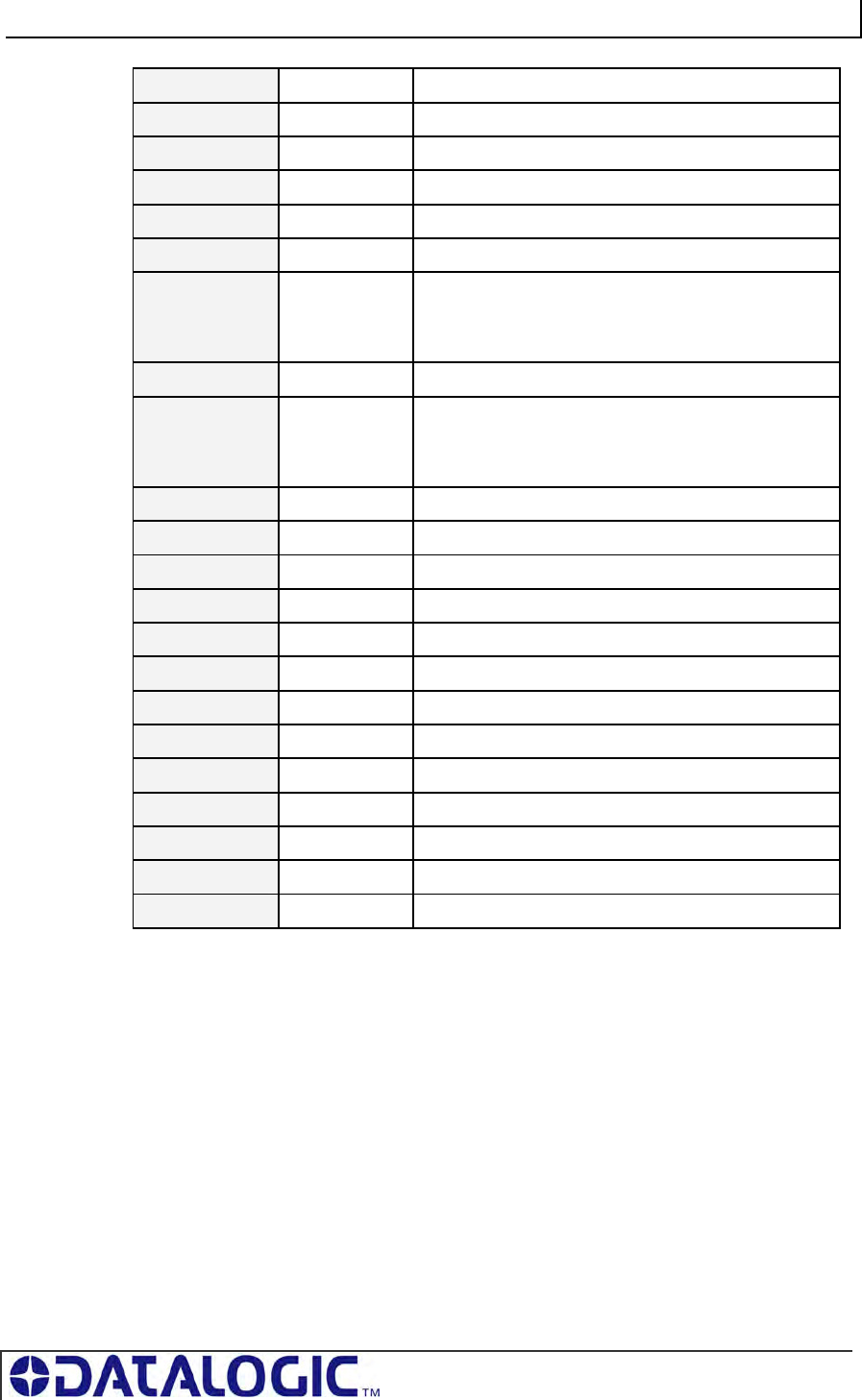
COBALT UHF-SERIES CHAPTER 7: MODBUS TCP INTERFACE
PAGE 117 OF 140
13 RO MAC Address 1 (MSB) Example: 0x00
14 RO MAC Address 2 Example: 0x40
15 RO MAC Address 3 Example: 0x9D
16 RO MAC Address 4 Example: 0x12
17 RO MAC Address 5 Example: 0x34
18 RO MAC Address 6 (LSB) Example: 0x56
19 RO Link Status:
0 = No Link
1 = Link is OK
20 RO Ethernet Speed (10M or 100M bits)
21 RO Link Duplex:
0 = Half Duplex
1 = Full Duplex
22 RO Revision (Major/Minor)
23 – 1000 R/W Reserved
1001 RO (Input) Data Ready Mask - Nodes 1 - 16
1002 RO (Input) Data Ready Mask - Nodes 17 - 32
1003 RO (Output) Data Ready Mask - Nodes 33 - 48
1004 RO (Output) Data Ready Mask - Nodes 49 - 64
1005-10099 R/W Reserved
10100 – 10199 R/W Reserved
10200 – 10299 R/W Reserved
… … …
13100 – 13199 R/W Reserved
13200 – 13299 R/W Reserved
13300 – 65536 R/W Reserved
Table 7-3: Modbus TCP - Mapping for Node 33

COBALT UHF-SERIES CHAPTER 7: MODBUS TCP INTERFACE
PAGE 118 OF 140
7.3 MODBUS TCP - HANDSHAKING
Due to the process with which commands and responses are passed between the
Cobalt and the host, a handshaking procedure is used to notify the host that returning
data is available for retrieval.
OVERALL LENGTH
The handshaking process is governed by the changing of the “Overall Length” value
within a data packet. The Overall Length value is typically the first word (2-bytes) of a
command or response and indicates the total number of data words in the packet.
NODE INPUT AND NODE OUTPUT PAGES
Under the Modbus TCP protocol, host-generated data is written to a pre-defined
region of the Cobalt’s own memory known as the Node Input Page. Host-bound data
generated by the Cobalt, is written to a separate region of the Cobalt’s memory
known as the Node Output Page (in Modbus TCP these regions of memory are
called Device IDs). Node Input and Node Output Pages are used to temporarily hold
incoming (controller-bound) and outgoing (host-bound) data.
OUTPUT DATA READY MASK
To notify the host that new data is waiting to be retrieved from the Node Output Page,
the Cobalt utilizes a separate 32-bit block of internal memory, called the Output Data
Ready Mask.
The first bit of the 32-bit Output Data Ready Mask represents the status of the Node
Output Page. For example, the first or lowest bit (bit 01) represents Node Output
Page 33 - which holds output data from Node 01.
The Cobalt, itself, is assigned Node 01 and thus, its corresponding Node Output
Page is 33. As noted, Node Output Page 33 is represented by the first bit (bit 01) in
the Output Data Ready Mask.
HOLDING REGISTERS
When writing host-bound data to Node Output Page 33, the Cobalt actually places
each byte of the data packet into pre-defined “holding registers” within the Node
Output Page. Note that a single holding register stores 2-bytes or one word of data.
The 2-byte Overall Length value, for example, is written to the first holding register
(which is location 40001) of the Node Output Page.
Then, as the Cobalt finishes writing host-bound data to the Node Output Page, the
Overall Length value (stored at holding register 40001) will change from its default
value of 0x00 to reflect the number of data words within the newly written host-bound
data packet. This change to the Overall Length value (i.e. register 40001) within the
Node Output Page, triggers the Cobalt to enable (change from zero to one) bit one in
the Output Data Ready Mask. It is when bit one in the Output Data Ready Mask has
become enabled, that the host will recognize the pending data.
Finally, after the host has retrieved its pending data, the enabled bit in the Output
Data Ready Mask and the Overall Length value at holding register 40001 of the Node
Output Page will be reset to zero (0x00), indicating that the host has received and
processed its pending data.
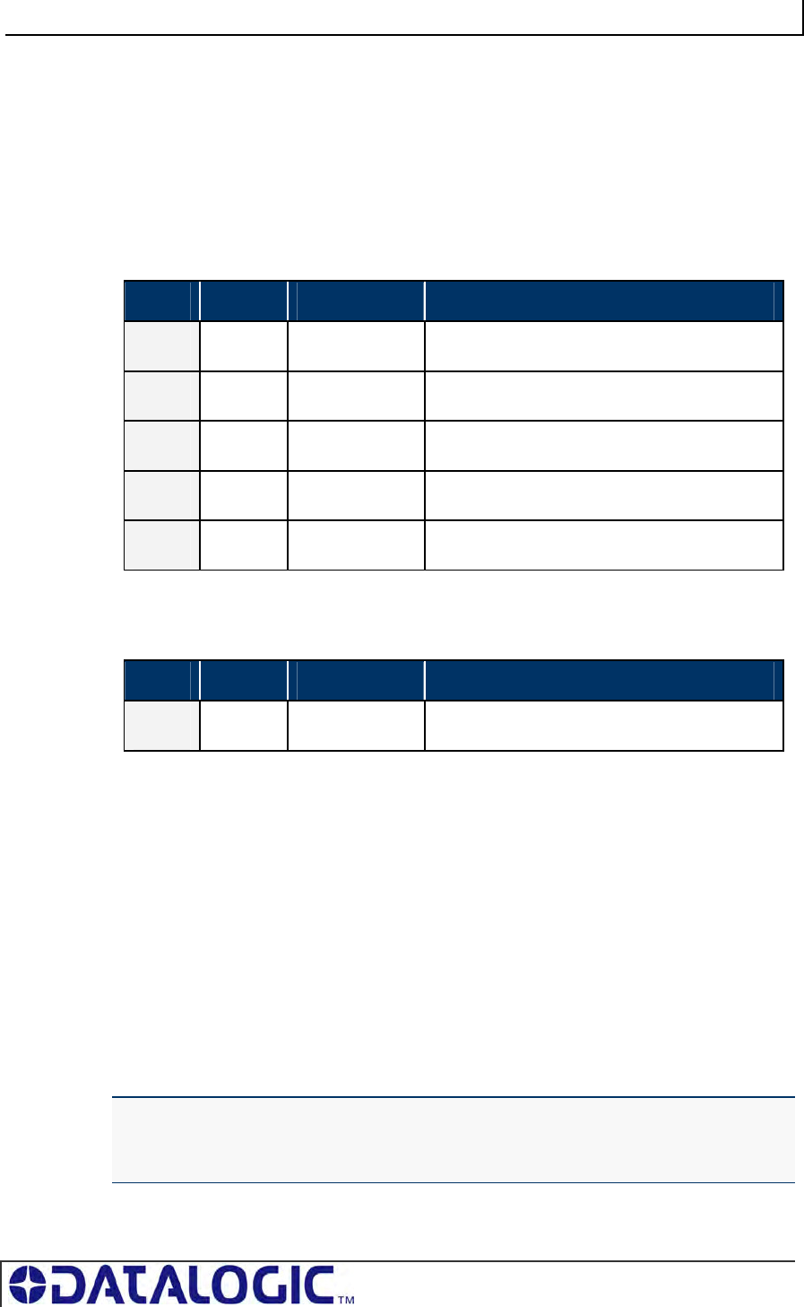
COBALT UHF-SERIES CHAPTER 7: MODBUS TCP INTERFACE
PAGE 119 OF 140
7.3.1 Modbus TCP - Host/Cobalt Handshaking
When the host issues a command, it must first write the entire command to the Node
Input Page, leaving the Overall Length value to be written last.
For example, for the host to issue the 6-word command “Read Data,” it must first
write the last five words of the command to Node Input Page 01, beginning at register
40002. After which, the host will fill in the first word (at holding register 40001) with
the Overall Length of the command packet.
Last Five Words of a Read Data Command
WORD MSB LSB DESCRIPTION
02 0xAA 0x05 Command ID: Read Data
03 0x00 0x01 Node ID: 0x01
04 0x03 0xE8 Timeout Value: 1 second
05 0x00 0x20 Read Start Address: 0x0020
06 0x00 0x04 Block Size: 4 Bytes
After writing the last five words of the command, the host will write the Overall Length
value to holding register 40001 of Node Input Page 01.
First Word of a Read Data Command
WORD MSB LSB DESCRIPTION
01 0x00 0x06 Overall Length (in words)
The moment the Overall Length value (at holding register 40001) of Node Input Page
01 changes from 0x0000 to a “non-zero” value, the Cobalt will recognize the waiting
data and will execute the command.
7.3.2 Modbus TCP - Handshaking Example
1. The host or PLC issues an RFID command to the Cobalt, writing the command
string to the holding registers for Device ID 01 (Node Input Page 01). An Overall
Length value of 0x0006 is written last to holding register 40001.
2. The Cobalt recognizes that the Overall Length value at holding register 40001
has changed for Device ID 01 (Node Input Page 01), indicating that a command
is waiting to be executed.
3. The Cobalt executes the command and then clears the Overall Length holding
register of Device ID 01 (Node Input Page 01), setting it back the default value of
zero (0x0000).
NOTE: when the Node Input Page’s value at register 40001 is returned to 0x0000, the
host can assume that the command was at least received and execution was
attempted. The host can also assume that it is OK to clear the remaining holding
registers and write another command to the Device ID (Node Input Page).
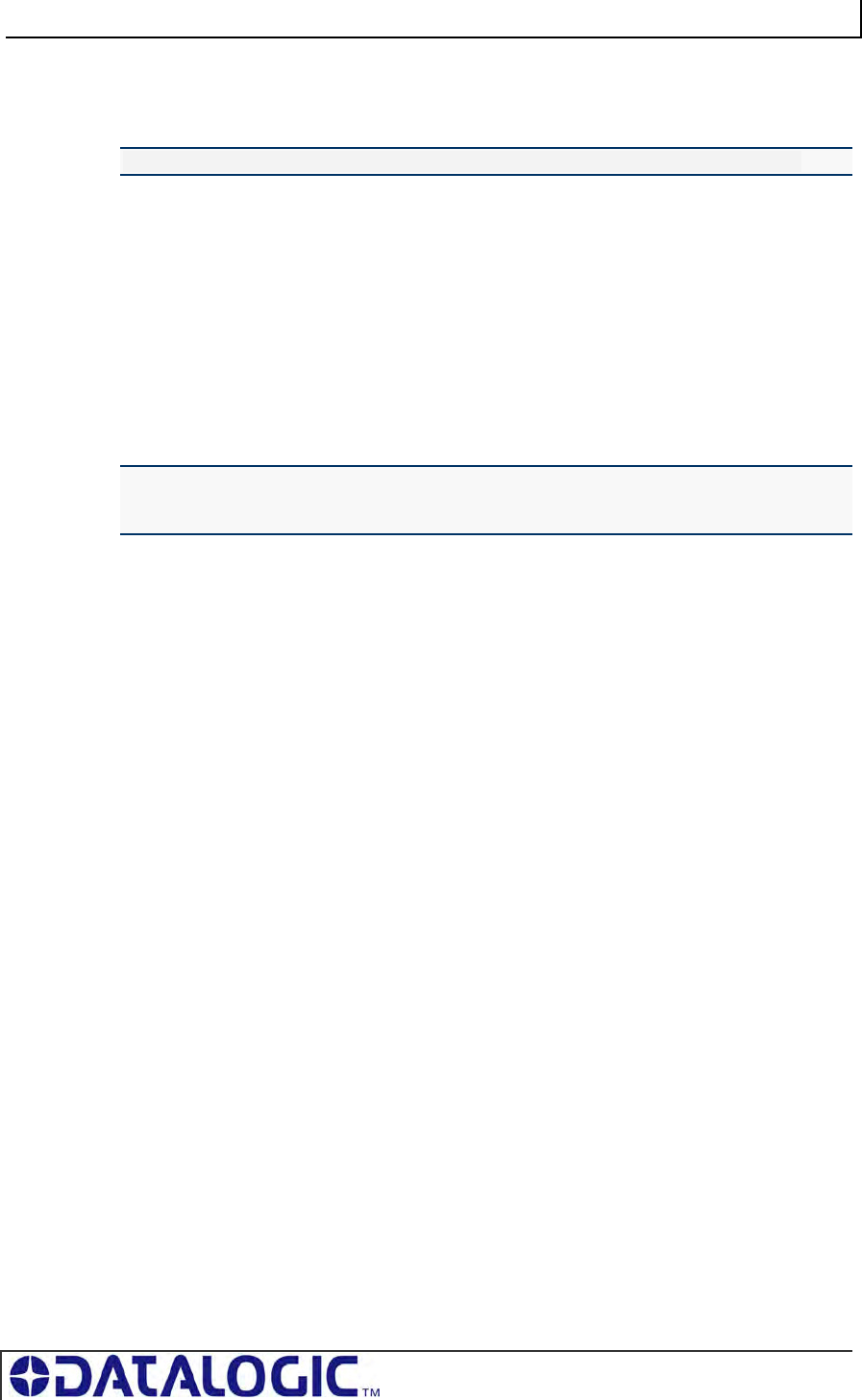
COBALT UHF-SERIES CHAPTER 7: MODBUS TCP INTERFACE
PAGE 120 OF 140
4. After the Cobalt executes its given command instructions, it will write the
command response to the holding registers for Device ID 33 (Node Output Page
33). Again, the Overall Length value is written last to holding register 40001.
NOTE: Host-bound data is always written to Device ID 33 (Node Output Page 33).
5. With holding register 40001 of Device ID 33 (Node Output Page 33) now
containing a non-zero length value, the Cobalt will enable (change from zero to
1) the first bit in the Output Data Ready Mask. (The first bit is allocated to Node
Output Page 33).
6. Once bit 01 in the Output Data Ready Mask becomes enabled, the host retrieves
the data string stored in the holding register area for Device ID 33 (Node Output
Page 33).
7. After importing the data from Device ID 33 (Node Output Page 33), the host
clears (sets back to 0x0000) the Overall Length value at holding register 40001
of Device ID 33 (Node Output Page 33). In doing so, bit 01 in the Output Data
Ready Mask is also cleared.
NOTE: the clearing of bit 01 in the Output Data Ready Mask indicates to the Cobalt that
the host has received the response and that it is now OK to write another response to
Node Output Page 33.
This completes the Modbus TCP handshaking cycle.
COBALT UHF-SERIES CHAPTER 8: STANDARD TCP/IP INTERFACE
PAGE 121 OF 140
CHAPTER 8:
STANDARD TCP/IP INTERFACE
8.1 STANDARD TCP/IP OVERVIEW
Another means of communicating with the Cobalt is through the standard TCP/IP
protocol. For this manual, the protocol is referred to as standard TCP/IP to
distinguish it from other industrial protocols.
In this environment, the Cobalt acts as the server and the host or PLC acts as client.
Standard TCP/IP sessions are established between the host computer and the
Cobalt via TCP/IP client software. A TCP/IP session generally consists of three
stages: connection setup, data transactions and connection termination.
All connections to the Cobalt are initiated by client side software only. If, for example,
an existing connection terminates unexpectedly, the Cobalt will not attempt to contact
the client software or re-establish a connection. The client is responsible for opening,
maintaining, and closing all TCP/IP sessions.
After establishing a successful connection, communications between the host and
the Cobalt can proceed. When communication is no longer necessary, it is the
responsibility of the client side application to terminate the connection.
ATTENTION:
• The TCP/IP client software (running on the host or PLC) must connect to the TCP/IP
server (Cobalt) on port 50200
• Maximum number of words transferred to/from an RFID tag per read/write cycle: 100
Words / 200 Bytes
• Disable any firewall services running on the PC. Firewalls can potentially block
communications between the Cobalt and the host and/or PLC
8.2 STANDARD TCP/IP - IP CONFIGURATION VIA
HTML
S
ERVER
To configure the Cobalt for standard TCP/IP communications, begin by assigning the
controller a locally compatible IP address.
Through a standard Web browser, you can utilize the Cobalt’s HTML Server to
access an embedded suite of controller configuration tools, called the “OnDemand
Utilities.” Among its features is the ability to modify and save changes to the
controller’s IP address, which is stored internally on the Cobalt.
Cobalt Industrial Ethernet RFID Controller Default IP Address:
192.168.253.110
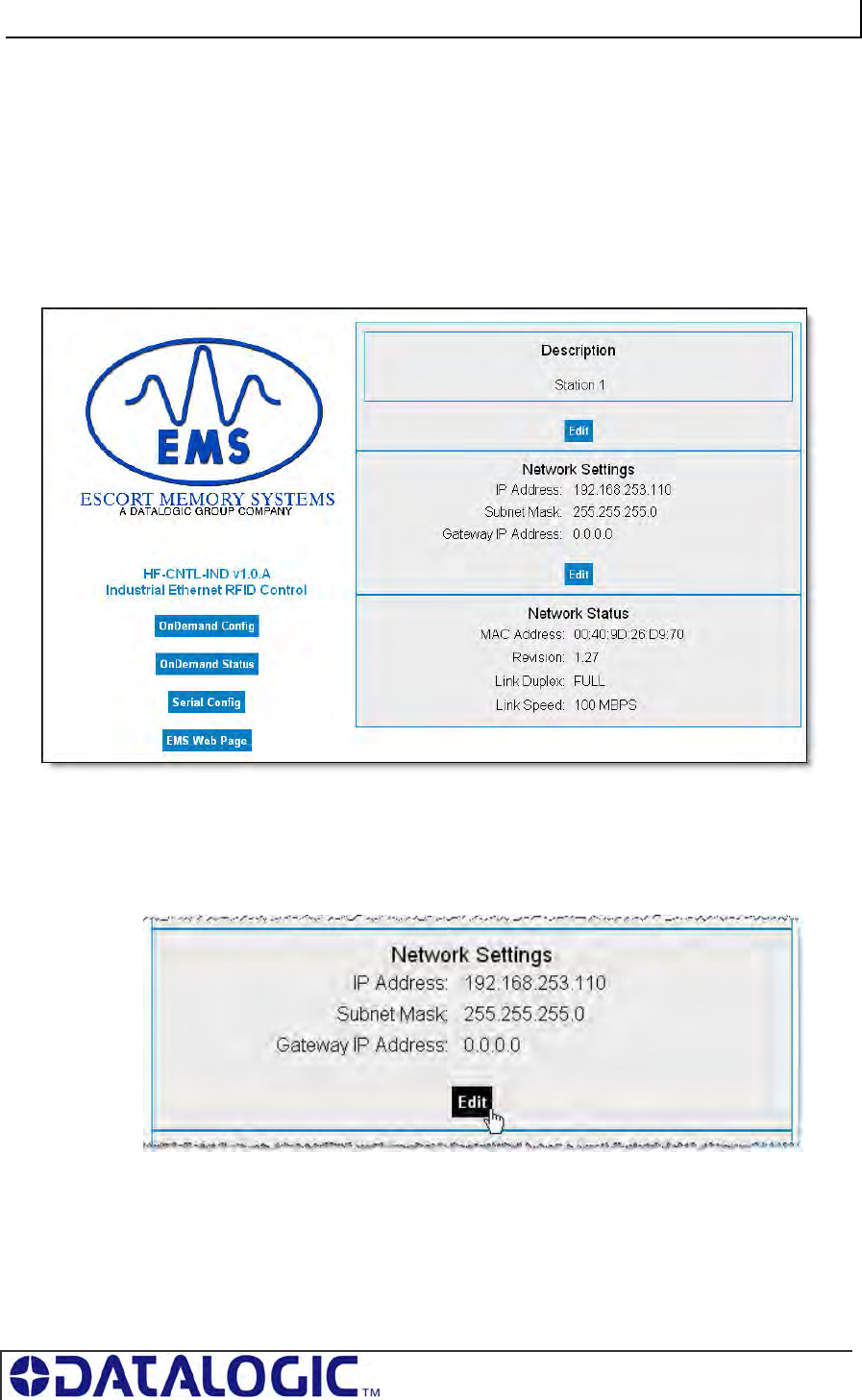
COBALT UHF-SERIES CHAPTER 8: STANDARD TCP/IP INTERFACE
PAGE 122 OF 140
8.2.1 Setting the IP Address of the Cobalt
To set the Cobalt’s IP address using the HTML Server, follow the steps below:
1. Open a Web browser on the PC.
2. In the URL address field, enter the Cobalt’s IP address (192.168.253.110 =
factory default).
3. Press ENTER.
The HTML Server - Main Page will be displayed.
Figure 8-1: The HTML Server - Main Page
The HTML Server - Main Page lists the network settings (including the IP address)
currently stored on the Cobalt.
4. Click the button labeled “EDIT”, located below “Network Settings.”
The IP Configuration Page will be displayed.
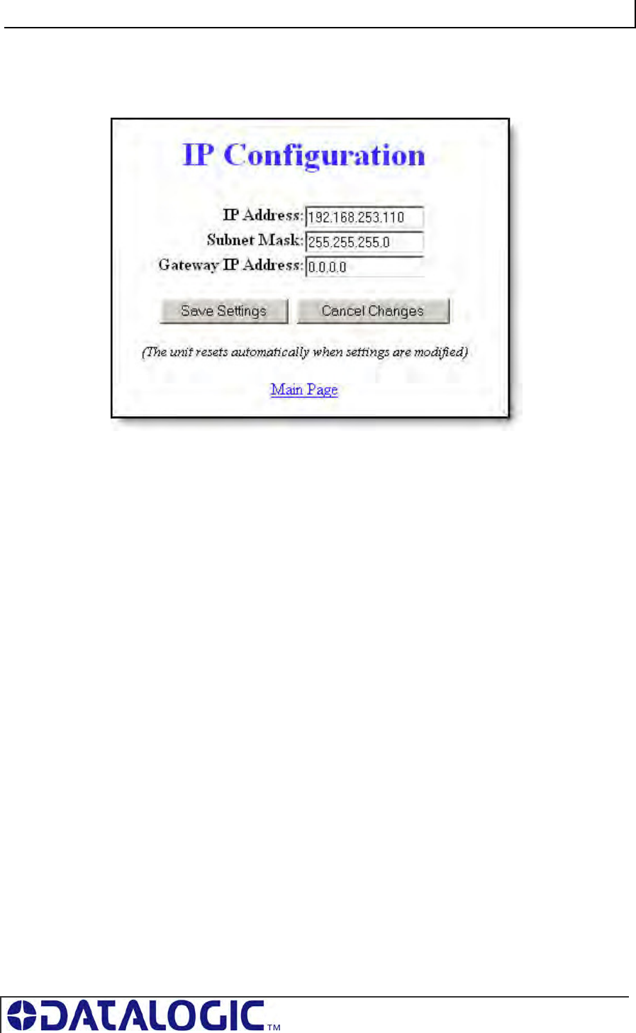
COBALT UHF-SERIES CHAPTER 8: STANDARD TCP/IP INTERFACE
PAGE 123 OF 140
IP CONFIGURATION PAGE
The IP Configuration Page is used to modify and save changes to the IP Address,
Subnet Mask and (Network) Gateway IP Address.
Figure 8-2: The IP Configuration Page
5. In the fields provided, enter your new IP configuration values for the Cobalt.
6. Click the “Save Settings” button to store your new IP configuration. The Cobalt
will completely reset and your IP changes will be implemented.
7. After the Cobalt has restarted, verify the new IP configuration by opening a Web
browser and manually entering the Cobalt’s new IP address in the URL field. If
successful, you should arrive back at the HTML Server – Main Page.
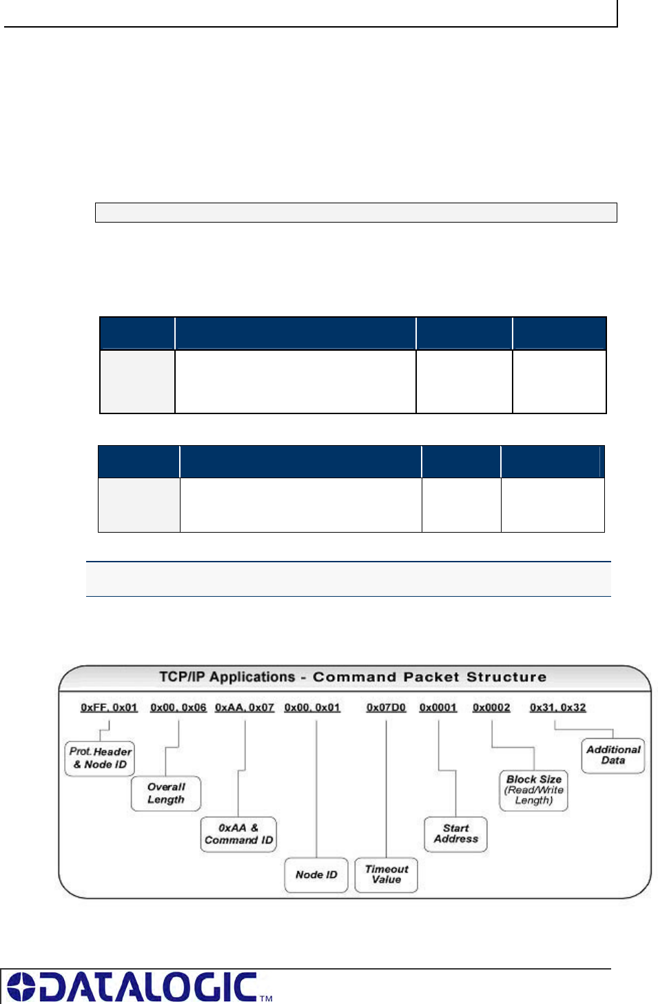
COBALT UHF-SERIES CHAPTER 8: STANDARD TCP/IP INTERFACE
PAGE 124 OF 140
8.3 STANDARD TCP/IP - COMMAND & RESPONSE
EXAMPLES
In standard TCP/IP, RFID commands issued by the host resemble Modbus TCP
commands. The Cobalt handles all handshaking tasks.
Moreover, the command & response packets need an additional word at the
beginning of the string:
Protocol Header 0xFF in MSB, <Node ID> in LSB.
Please notice that these two bytes are not considered part of the CBx command
packet and should not be counted in the Overall Length.
Below is the structure of the additional word required, named as Word # 00:
WORD # COMMAND PACKET ELEMENT MSB LSB
00 Protocol Header in MSB: 0xFF
Node ID in LSB
0xFF <Node ID>
And similarly for the response:
WORD # RESPONSE PACKET ELEMENT MSB LSB
00 Protocol Header
in MSB: 0xFF
Node ID Echo in LSB
0xFF <Node ID
Echo>
NOTE: These first two bytes will not be returned in the response packet for commands
executed by Node 01.
Therefore, the command packet structure for standard TCP/IP applications is:
Figure 8-3: Standard TCP/IP Protocol Command Packet Structure
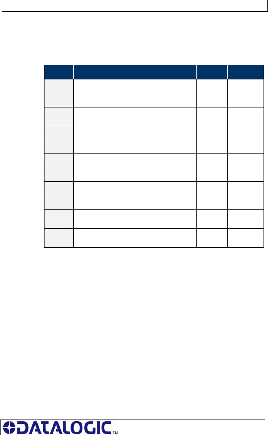
COBALT UHF-SERIES CHAPTER 8: STANDARD TCP/IP INTERFACE
PAGE 125 OF 140
8.3.1 Standard TCP/IP - Command Structure & Example
In the following example, a 12-byte command has been issued to the Cobalt,
instructing the controller to read six bytes from a tag within RF range. A Timeout
Value of five seconds has been set for the completion of the command.
WORD DESCRIPTION MSB LSB
00 Protocol Header in MSB = 0xFF
Node ID in LSB = default value for Cobalt -IND is
one (0x01)
0xFF 0x01
01 Overall Length: 2-byte integer indicating number
of “words” in the command packet
0x00 0x06
02 MSB = 0xAA
LSB = Command ID: (example: 0x05 – Read
Data)
0xAA 0x05
03 MSB = 0x00
LSB = Node ID: default value for Cobalt -IND is
one (0x01)
0x00 0x01
04 Timeout Value: 2-byte integer measured in .10
(1/10th) second increments.
(0x0032 = 50 x .10 or 5 seconds)
0x00 0x32
05 Start Address: 2-byte integer identifies tag
address where read will begin
0x00 0x01
06 Block Size: 2-byte integer indicates number of
bytes to retrieve
0x00 0x06
Table 8-1: Standard TCP/IP - Command Structure & Example
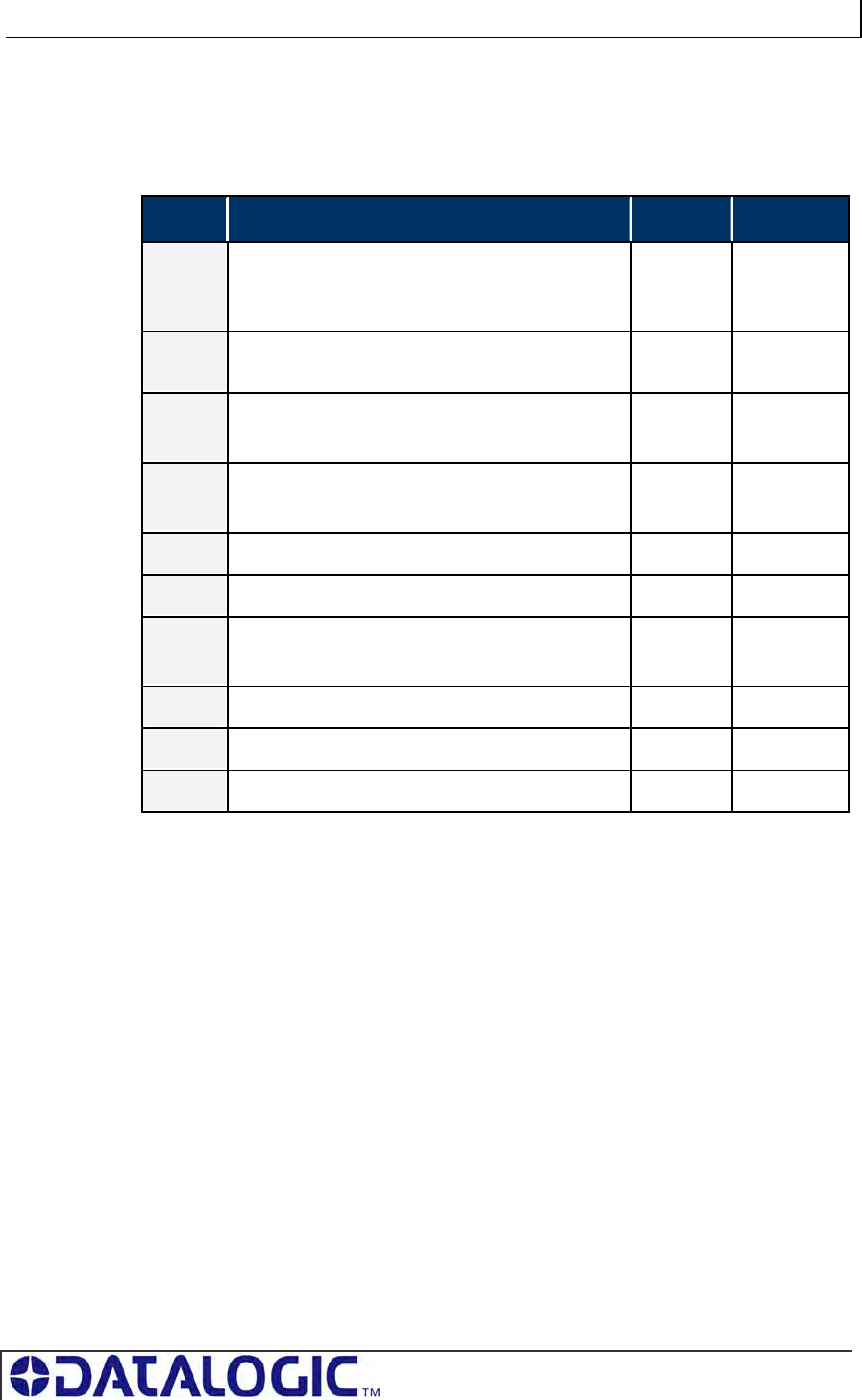
COBALT UHF-SERIES CHAPTER 8: STANDARD TCP/IP INTERFACE
PAGE 126 OF 140
8.3.2 Standard TCP/IP - Response Structure & Example
The following resembles a typical response to the command issued in the previous
example:
WORD DESCRIPTION MSB LSB
00 Protocol Header in MSB = 0xFF
Node ID in LSB = default value for Cobalt -IND is
one (0x01)
0xFF 0x01
01 Overall Length: 2-byte integer indicating number
of “words” in the response packet
0x00 0x09
02 MSB = 0xAA
LSB = Command Echo: (0x05 - Read Data)
0xAA 0x05
03 MSB = Instance Counter
LSB = Node ID: 0x01
<IC> 0x01
04 Time Stamp: Month / Day (March 19th) 0x03 0x13
05 Time Stamp: Hour / Minute (8:15 a.m.) 0x08 0x0E
06 MSB = Time Stamp: Seconds
LSB = Number of Additional Bytes Retrieved: 6
0x00 0x06
07 Retrieved Bytes 1 & 2 0x61 0x62
08 Retrieved Bytes 3 & 4 0x63 0x64
09 Retrieved Bytes 5 & 6 0x65 0x66
Table 8-2: Standard TCP/IP - Response Structure & Example
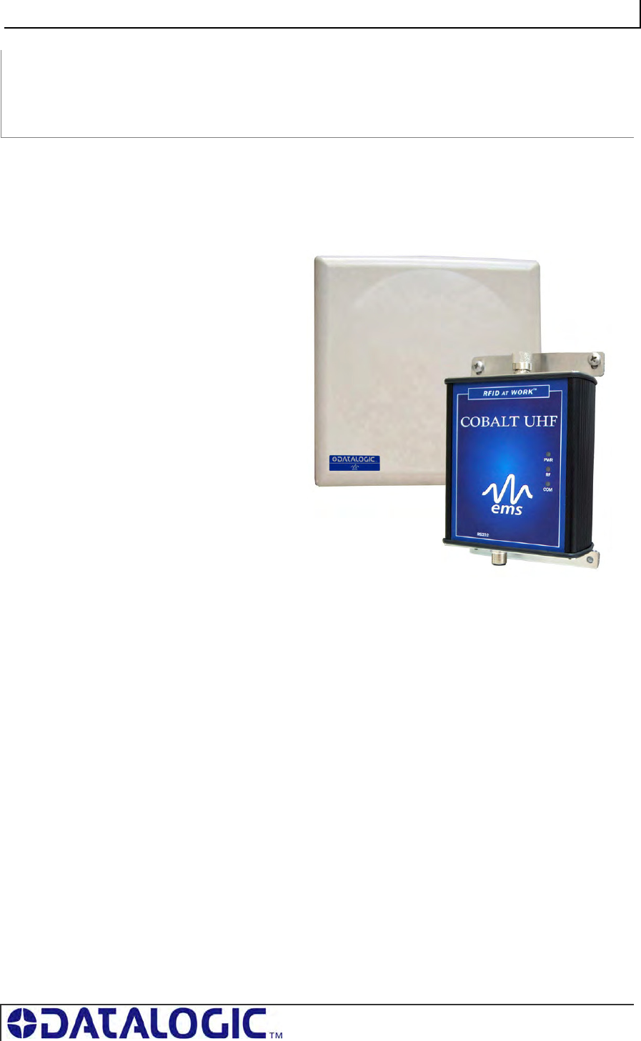
COBALT UHF-SERIES CHAPTER 9: RFID OVERVIEW
PAGE 127 OF 140
CHAPTER 9:
RFID OVERVIEW
9.1 RFID OVERVIEW
Cobalt UHF-Series products
are designed for use with
passive RFID tags, which do
not require batteries or
contain an internal power
supply. The tags collect the
power necessary to operate
from the RF field generated
by the reader and through a
process called backscattering
they can reflect some of this
power back to the reader,
thus creating a
communication channel.
When a passive tag comes in
contact with the RF field from
an RFID antenna, the
incoming radio frequency
signal generates a small, but
sufficient, electrical current
that powers the passive tag’s integrated circuit (IC)
When mounting RFID antennas and tags, it is important to understanding certain
principles. If your RFID application requires that the tag be attached directly to a
metal surface, always use a non-metallic tag spacer to avoid a possible reduction in
read/write range.
In addition, motors, conveyors and other automation equipment can produce
excessive electrical noise that may also negatively affect RF performance. Cobalt
UHF-Series products should only be used with well-grounded systems. Conveyor
equipment should be tied directly to an earth ground by an electrician. All cables
used on or around Cobalt UHF RFID devices must be shielded. Cable shields
typically should be grounded at only one end.
The majority of the Antenna-to-Tag range results specified in this publication were
measured in a free air environment – where no metallic objects were within the
antenna’s RF field. Yet because proximity to metals and other environmental
conditions can adversely affect read and write range, it is not possible to state
absolute range results achieved under all conditions. System integrators should
validate the RF performance of the RFID products used and should not rely solely on
Datalogic’s published range specifications.
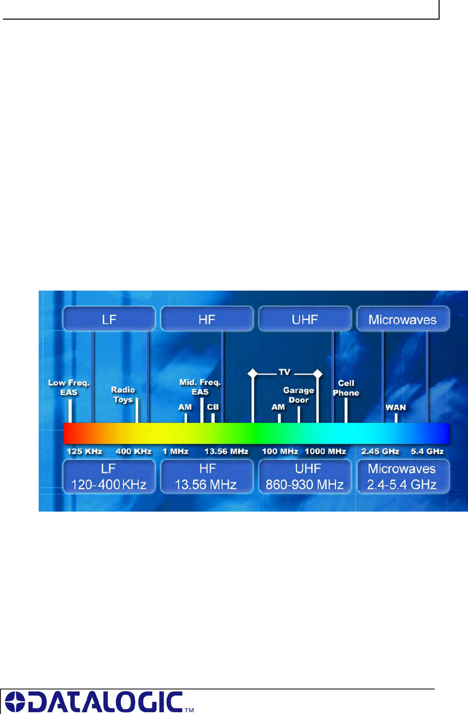
COBALT UHF-SERIES CHAPTER 9: RFID OVERVIEW
PAGE 128 OF 140
9.2 OVERVIEW ON ULTRA HIGH FREQUENCY RFID
APPLICATIONS
9.2.1 UHF Standards and Regulations
One of the most important aspects of a tag and reader coupling is the frequency at
which it operates. Frequency of operation can vary based on the application,
standards, and regulations.
The most common RFID frequency ranges are Low Frequency (LF) at 135kHz or
less, High Frequency (HF) at 13.56MHz, Ultra High Frequency (UHF) starting at
300MHz. Microwave Frequency at 2.45GHz and 5.4GHz is also used in some
applications.
Ultra High Frequency (UHF) designates a range (or band) of electromagnetic waves
with frequencies between 300 MHz and 2.45 GHz (2,450 MHz).
Figure 9-1: Radiowaves Spectrum Diagram
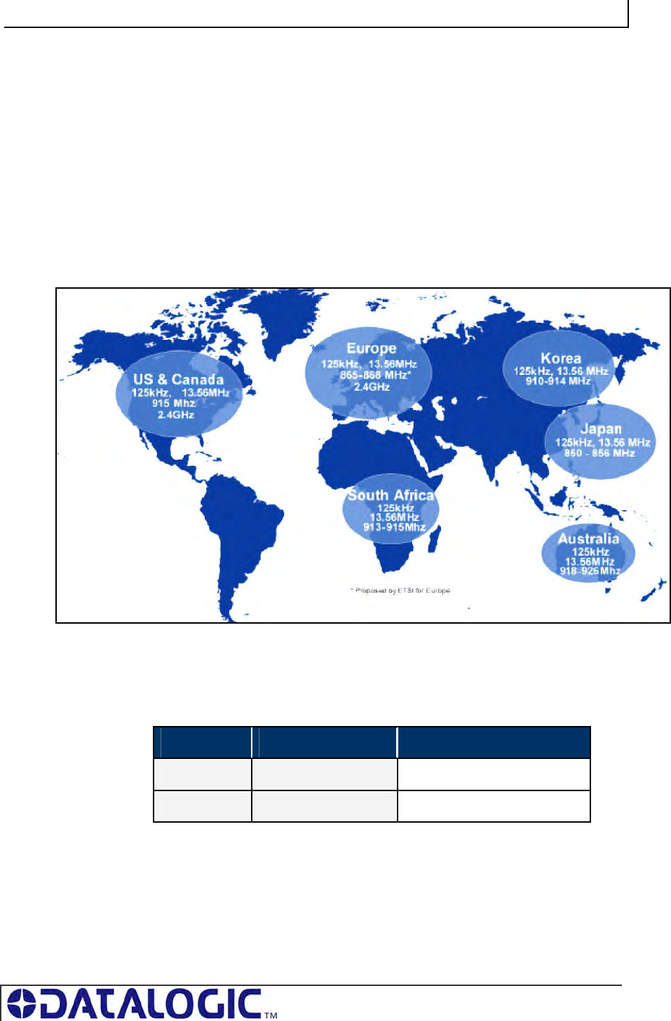
COBALT UHF-SERIES CHAPTER 9: RFID OVERVIEW
PAGE 129 OF 140
There are different UHF operating frequency standards all over the world, regulated
by governmental authorities in most countries: for instance, Federal Communications
Commission (FCC) in the United States and ETSI (European Telecommunications
Standards Institute) in Europe.
Globally, each country has its own frequency allocation for RFID.
For instance, RFID UHF bands are:
865–870 MHz in Europe
902–928 MHz in North and South America
950–956 MHz in Japan and some Asian countries
Figure 9-2: Radiofrequency Bands Allocation
With reference to power limits, the maximum allowed reader radiated power is 4
Watts in the US, and 2 Watts in Europe.
REGION REGULATIONS RADIATED POWER
USA FCC Part 15 4 W EIRP (36 dBm)
Europe EN 302 208 2 W ERP (35 dBm)
Table 9-1:Reader Radiated Power Limits Expressed in Watt or dBm
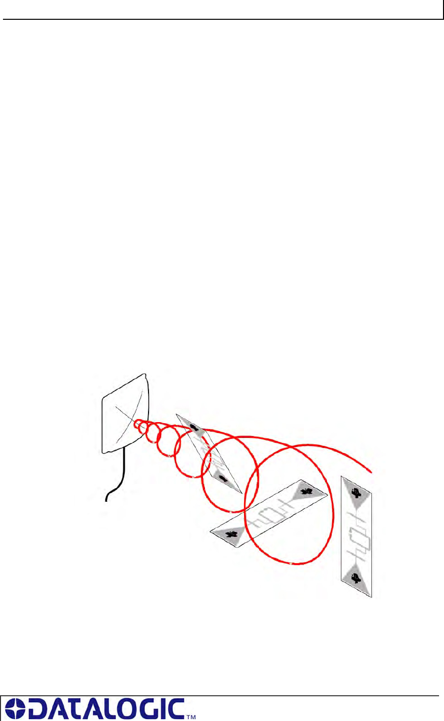
COBALT UHF-SERIES CHAPTER 9: RFID OVERVIEW
PAGE 130 OF 140
9.2.2 UHF Signal Propagation
In general, the frequency defines the data transfer rate (speed) between the tag and
the reader. For this reason, UHF systems feature long range, and high speed
read/write rates.
Small antennas and even smaller tags have proven this to be an effective frequency
for tracking pallets through dock doors, as well as trucking and transportation
applications. Industrial UHF applications have also begun to effectively be developed
for tracking parts, product and carriers through production.
In this context, Cobalt UHF is ideal for industrial applications where single or multiple
tags must be read at long distance and at high speed.
The main advantage of UHF transmission is the physically short wave that is
produced by the high frequency. The size of transmission and reception equipment,
(particularly antennas), is related to the size of the radio wave.
The higher the frequency, the shorter the wavelength for RF transmission. Without
going into the details of the physics, the shorter the wavelength, the better a small
antenna like an RFID tag is able to receive a transmission at greater distances.
Therefore, smaller and less conspicuous antennas can be used with higher
frequency bands.
For the Cobalt UHF- Series product line, Datalogic offers a range of circular polarized
antennas, for which tag orientation is less critical.
In effect, the helical nature of the field from a circular polarized antenna allows it to
read tags in random orientation.
Figure 9-3: Circular Polarized Antenna’s Field Pattern
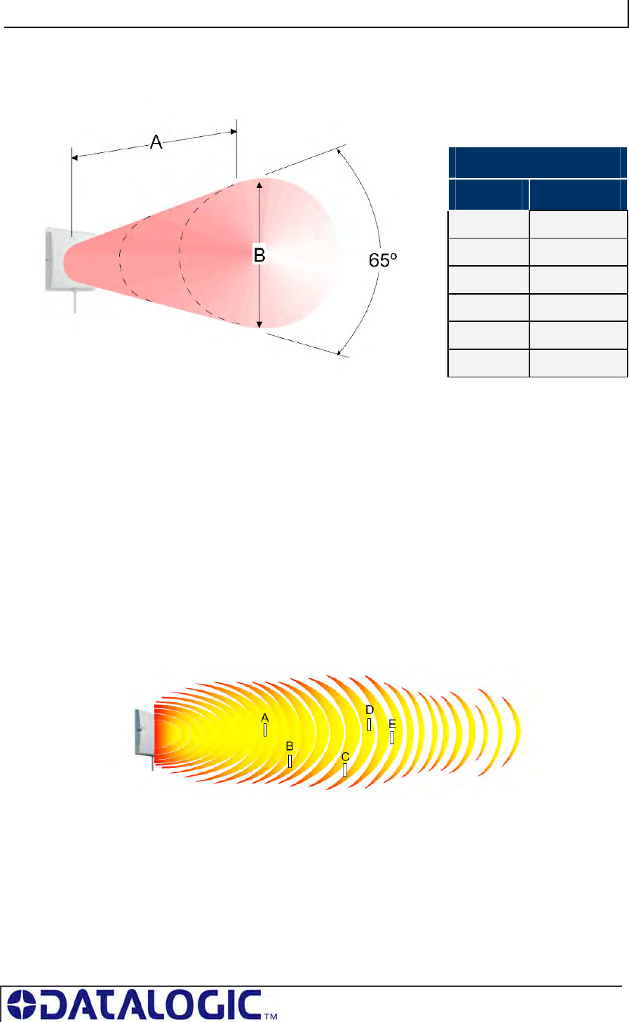
COBALT UHF-SERIES CHAPTER 9: RFID OVERVIEW
PAGE 131 OF 140
Furthermore, the Cobalt UHF antennas feature a 3dB Beamwidth, 63° or 65°,
providing a large reading zone.
Figure 9-4: Circular Polarized Antenna’s Reading Range
As considered above, the ability for signals to propagate within environment is
dependent on the signal wavelength, and hence frequency. UHF will have challenges
with crowded environments: within warehouses, truck yards, and other facilities, the
ability for an RFID system to operate in and around obstructions is critical.
These obstructions are often metallic, such as vehicles and metal shelving racks,
requiring signals to propagate “around” rather than “through” the obstructions. For
that reason, for industrial applications involving significant environmental obstructions
HF is a preferred frequency.
At UHF frequencies, multi-path RF waves caused by reflections from the floor and
other obstructions may combine constructively or destructively. When these signals
are in-phase they combine to give a stronger signal, but when out-of-phase, they
cancel and create ‘reading holes that get worse with distance from the antenna.
Therefore, referring to the picture above:
Tags A and D are in strong zones and will read.
Tag B will read if its antenna is long enough to ‘span the gap’
Tag C and E will not read
3 DB BEAM WIDTH
A B
0.5 0.6
1.0 1.3
1.5 2.0
2.0 2.6
2.5 3.1
3.0 3.7

COBALT UHF-SERIES CHAPTER 9: RFID OVERVIEW
PAGE 132 OF 140
All materials reduce the power of the RF signal to some extent, but direct contact on
metals and liquids can cause particular problems:
Metals reflect the signal. A metal object may change the tuning of a tag (or
frequency on which it can receive signals), reflecting the RF waves from a
reader, or block communication from a specific antenna.
Liquids (including atmospheric moisture) absorb the signal. All radio waves
are partially absorbed by atmospheric moisture. Atmospheric absorption reduces,
or attenuates, the strength of radio signals over long distances. In addition, the
effects of attenuation increases according to the frequency; thereby, UHF signals
are generally more degraded by moisture than lower bands.
9.2.3 Limiting Interference and UHF Signal Attenuation
The following hints may be useful to get the best performance from your RFID
application.
Reading holes can be reduced in a number of ways:
By removing metal from the reading area: if the reflections can be reduced so
will the holes
By movement of the tag past the antenna.
As the tag moves, it will cross the holes and be read at some point. The exact
speed is a compromise between the number of tags and the bandwidth of the
system. Because of Governmental regulation, for instance, readers are capable
of reading more tags in the same time in the USA than is possible in Europe.
Multiple readers operating in the same environment may interfere with one another.
A number of techniques can help limit these unwanted effects:
Use photo-cell triggering to initiate reading - don’t have the reader
transmitting all the time
Reduce the power
Reduce the downlink rate
Shield between reading systems with absorptive material (metals could make
the problem worse)
Most important, testing should be performed in the actual environment to achieve
more precise range results.
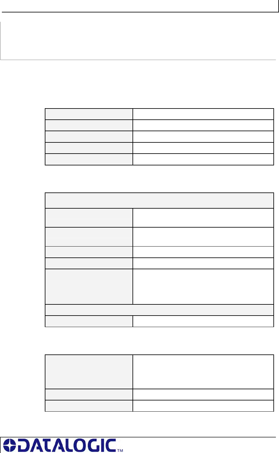
COBALT UHF-SERIES APPENDIX A: TECHNICAL SPECIFICATIONS
PAGE 133 OF 140
APPENDIX A:
TECHNICAL SPECIFICATIONS
COBALT UHF CONTROLLERS - TECHNICAL SPECIFICATIONS
ELECTRICAL
DC Input Voltage Range 12 – 30 VDC
Power 6.7 W (280 mA @24 VDC)
Reverse Polarity Protection Series Diode protection on DC power pins
Tolerable Ripple 100 mVpp
Over-current Protection 1 amp internal limit
RADIO
Transmitter
Frequency 902 to 928 MHz (FCC part 15)
865.600 to 867.600 (ETSI EN 302 208)
Output Power Programmable in 8 steps
up to 500 mW conducted @ 5 V (27 dBm)
Antenna Connector Reverse TNC
Frequency Tolerance ±10 ppm over the entire temperature range
Number of Channels 10 channels
(compliant to ETSI EN 302 208)
50 hopping channels
(compliant to FCC part 15)
Air Interface
Standard Compliance EPC C1G2
COMMUNICATION
UHF-CNTL-232-02 Point-to-Point: RS232
Baudrate: 9.6 to 115 kbit/s data rate (configurable)
Data Bits: 8; Stop Bits: 1; Parity: none; Flow
control: none
UHF-CNTL-485-02 Multi-drop: Subnet16 (RS485)
UHF-CNTL-IND-02 Ethernet: Ethernet/IP, MODBUS TCP, TCP/IP
COBALT UHF-SERIES APPENDIX A: TECHNICAL SPECIFICATIONS
PAGE 134 OF 140
MECHANICAL
Dimensions 163mm (6.4 inches) H x 112mm (4.4 inches) L x
48mm (1.9 inches) W
Weight .56 KG (.97 lb., 560 grams)
Enclosure Powder-coated Aluminum
ENVIRONMENTAL
Operating Temperature -20° to 50°C (-4° to 122°F),
Storage Temperature -40° to 85°C (-40° to 185°F)
Humidity 90% non-condensing
Protection Class IP65
Shock Resistance IEC 68-2-27 Test EA 30g,
11 milliseconds, 3 shocks each axis
Vibration Resistance IEC 68-2-6 Test FC 1.5mm; 10 to 55Hz;
2 hours each axis
NOTE: Specifications are subject to change without notice.
COBALT UHF-SERIES APPENDIX A: TECHNICAL SPECIFICATIONS
PAGE 135 OF 140
COBALT UHF ANTENNAS - TECHNICAL SPECIFICATIONS
ELECTRICAL
UHF-ANT-2626-01-86
Frequency Range 865 - 870 MHz
Gain 8.5 dBic (min) - 9.5 dBic (max)
3 dB Beamwidth 65° (typ)
Polarization RHCP
Input Impedance 50 (Ohm)
Input Power 6 Watt (max)
UHF-ANT-3030-01-91
Frequency Range 902 – 928 MHZ
Gain 9 dBic (min) - 10 dBic (max)
3 dB Beamwidth 63° (typ)
Polarization RHCP
Input Impedance 50 (Ohm)
Input Power 6 Watt (max)
MECHANICAL
UHF-ANT-2626-01-86
Dimensions (LxWxD) 260x260x30 mm (max)
Weight 1 Kg (max)
Connector N – type female
UHF-ANT-3030-01-91
Dimensions (LxWxD) 305x305x25 mm
Weight 1,2 Kg (max)
Connector N – type female
NOTE: Specifications are subject to change without notice.
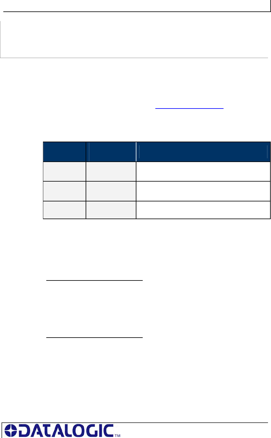
COBALT UHF-SERIES APPENDIX B: MODELS & ACCESSORIES
PAGE 136 OF 140
APPENDIX B:
MODELS & ACCESSORIES
Datalogic Automation designs, manufactures and distributes a wide range of ultra
high frequency (UHF) RFID equipment, including RFID controllers, network interface
modules (Gateways and Hubs), RFID tags and the cables needed to make it all work.
This portion of the manual lists the products and accessories available for the Cobalt
UHF-Series RFID product family. To purchase any of the items listed below contact
your EMS distributor or visit our Web site: http://www.ems-rfid.com.
COBALT UHF SERIES ACCESSORIES
The following accessories are available for the Cobalt UHF Series RFID Controllers:
MODEL PART
NUMBER DESCRIPTION
UHF-CBL-01 970106002 Coaxial Cable Controller-Antenna, TNC-Reverse
Male to N-Plug Male, 1 meter
UHF-CBL-03 970106003 Coaxial Cable Controller-Antenna, TNC-Reverse
Male to N-Plug Male, 3 meters
Mounting Kit
for Antenna 970103035 Mounting Kit for large size UHF Antennas
Table Appendix B-1:Cobalt UHF Series Accessories
COBALT UHF-SERIES RFID CONTROLLERS
There are six models of the Cobalt UHF RFID Controllers:
EU- BAND MODELS (865-870 MHZ)
UHF-CNTL-232-02 EU for RS232 interface connections
UHF-CNTL-485-02 EU for Subnet16 Multidrop connections
UHF-CNTL-IND-02 EU for Ethernet Industrial interface connections
US- BAND MODELS (902-928 MHZ)
UHF-CNTL-232-02 US for RS232 interface connections
UHF-CNTL-485-02 US for Subnet16 Multidrop connections
UHF-CNTL-IND-02 US for Ethernet Industrial interface connections
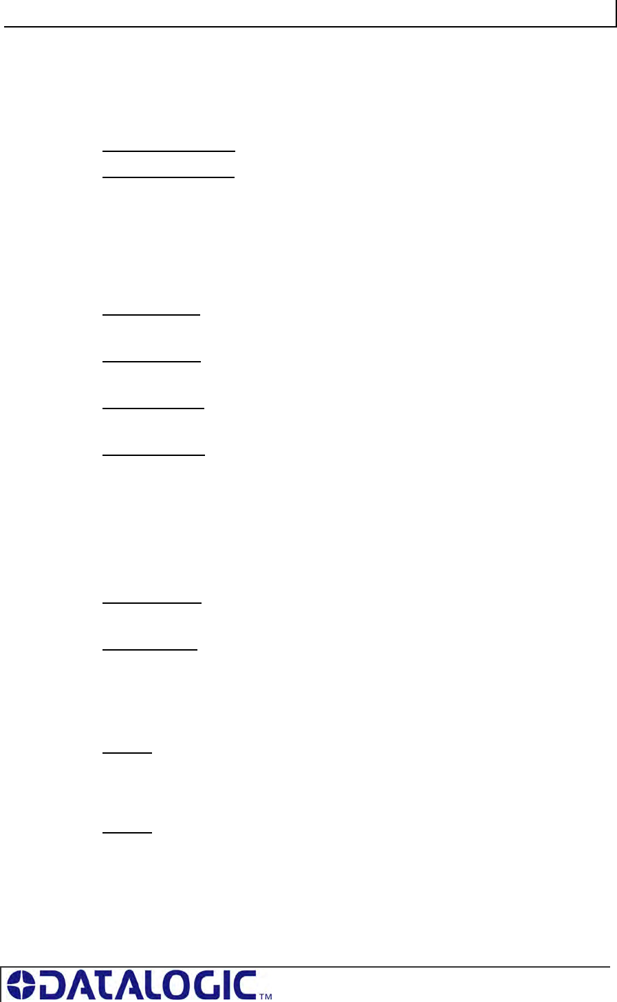
COBALT UHF-SERIES APPENDIX B: MODELS & ACCESSORIES
PAGE 137 OF 140
COBALT UHF-SERIES ANTENNAS
(COMPATIBLE WITH THE UHF SERIES CONTROLLERS ABOVE)
There are two models of the Cobalt UHF RFID Antenna:
UHF-ANT-2626-01-86 26cm x 26cm, 868 MHz
UHF-ANT-3030-01-91 30cm x 30cm, 915 MHz
SUBNET16 GATEWAYS
(COMPATIBLE WITH THE UHF-CNTL-485-02 CONTROLLER MODEL)
There are four models of the Subnet16 Gateway:
GWY-01-232-01
Subnet16™ RS232 Gateway
GWY-01-IND-01
Subnet16™ Industrial Ethernet Gateway
GWY-01-TCP-01
Subnet16™ TCP/IP Gateway
GWY-01-DNT-01
Subnet16™ DeviceNet Gateway
SUBNET16 HUBS
(COMPATIBLE WITH THE UHF-CNTL-485-02 CONTROLLER MODEL)
There are two models of the Subnet16 Hub.
HUB-04-TCP-01
Subnet16™ TCP/IP Hub (4-port)
HUB-04-IND-01
Subnet16™ Industrial Ethernet Hub (4-port)
POWER SUPPLIES
00-1166
1.88A max @ 24VDC (45W), Universal Input (90-264VAC, 47-63Hz), 5.5x2.5mm
plug, positive tip (requires country specific power cord to mate to IEC 320 power cord
receptacle).
00-1167
4.17A max @ 24VDC (100W), Universal Input (90-264VAC, 47-63Hz), 5.5x2.5mm
plug, positive tip (requires country specific power cord to mate to IEC 320 power cord
receptacle).
COBALT UHF-SERIES APPENDIX B: MODELS & ACCESSORIES
PAGE 138 OF 140
00-1168
5.0A max @ 24VDC (120W), Universal Input (88-132VAC/176-264VAC switch
selectable, 47-63Hz) DIN Rail Mount (AC wire receptacles are spring clamped for
direct wire connections).
SOFTWARE APPLICATIONS
Visit the Escort Memory Systems website (www.ems-rfid.com) for download
instructions.
Cobalt Dashboard
Communicate in real time with one or more readers directly or via Multi-drop network.
Allows users to configure, monitor and control their RFID devices from anywhere on
their network.
C-Macro Builder Utility
C-Macro Builder is an easy to use, GUI-driven utility that provides rapid development
and implementation of custom RFID command macros.
COBALT CABLES & ACCESSORIES
EMS P/N DESCRIPTION
CBL-1478 Cable Assembly: RS232, with 2.5mm DC Power Jack, 2m
CBL-1480-XX Cable: M12, 5-pin, Male/Female, ThinNet
CBL-1481-XX Cable: M12, 5-pin, Male/Male, ThinNet
CBL-1481-02 Cable: M12, 5-pin, Male/Male, ThinNet, 2m (Gateway to Drop-T)
CBL-1482-XX Cable: M12, 5-pin, Male/Right-Angle Female, ThinNet
CBL-1483-XX Cable: 7/8–16, 5-pin, Male/Female, ThickNet
CBL-1484-XX Cable: 7/8-16, 5-pin, Right-Angle Male/Bare Wire, ThickNet
CBL-1485 Drop-T Connector: 5-pin, 7/8-16 F / M12 F / 7/8-16 M (ThickNet to ThinNet)
CBL-1486 Drop-T Connector: 5-pin M12, F/F/M (ThinNet to ThinNet)
CBL-1487 Field Mountable Connector: 5-pos, Straight Female M12,
CBL-1488-XX Cable: 8-pin, Female M12 / Bare Wires
CBL-1489 Termination Resistor Plug: 7/8-16, Male, 5-pin, (ThickNet)
CBL-1490 Termination Resistor Plug: M12, Male, 5-pin, (ThinNet)
CBL-1491 Connector: 5-pos, Right-Angle Female M12, Field Mountable
COBALT UHF-SERIES APPENDIX B: MODELS & ACCESSORIES
PAGE 139 OF 140
CBL-1492-XX Cable: 8-pin, Right-Angle Female M12 / Bare Wires
CBL-1493 Connector: 8-pos, Straight Female M12, Field Mountable
CBL-1494-01 Cable: M12, 5P, F/Bare Wire Leads, ThinNet, 1M
CBL-1495-XX Cable: 7/8-16, 5P F/Bare Wire Leads
CBL-1496 Plug: Termination Resistor M12, 5P, F
CBL-1497 Plug: Termination Resistor, 7/8-16, 5P, F
CBL-1498-02 Cable: M12, 5P, M/Bare Wire Leads, ThinNet, 2M
CBL-1513 Cable Assembly: M12, 5-Pin, Male, Reverse Keyed to Type A, USB, 3M
CBL-1514 Connector: M12, Male, 5-Pin, Straight, Reverse Keyed (for USB)
CBL-1515-05 Cable: CAT5E Shielded Ethernet/M12, 5-Pin, Male, D-Code, 5M
Table Appendix B-2: Cobalt Cables and Accessories
XX = Length in Meters
COBALT UHF-SERIES WARRANTY
PAGE 140 OF 140
WARRANTY
Datalogic Automation warrants that all EMS RFID products of its own manufacturing
conform to Datalogic Automation’s specifications and are free from defects in material and
workmanship when used under normal operating conditions and within the service conditions
for which they were furnished. The obligation of Datalogic Automation hereunder shall expire
one (1) year after delivery, unless otherwise specified, and is limited to repairing, or at its
option, replacing without charge, any such product that in Datalogic Automation’s sole
opinion proves to be defective within the scope of this Warranty.
In the event Datalogic Automation is not able to repair or replace defective products or
components within a reasonable time after receipt thereof, Buyers shall be credited for their
value at the original purchase price. Datalogic Automation must be notified in writing of the
defect or nonconformity within the warranty period and the affected product returned to
Datalogic Automation factory or to an authorized service center within thirty (30) days after
discovery of such defect or nonconformity. Shipment shall not be made without prior
authorization by Datalogic Automation.
This is Datalogic Automation's sole warranty with respect to the products delivered
hereunder. No statement, representation, agreement or understanding oral or written, made by
an agent, distributor, representative, or employee of Datalogic Automation which is not
contained in this warranty, will be binding upon Datalogic Automation, unless made in writing
and executed by an authorized Datalogic Automation employee.
Datalogic Automation makes no other warranty of any kind what so ever, expressed or
implied, and all implied warranties of merchantability and fitness for a particular use which
exceed the aforementioned obligation are here by disclaimed by Datalogic Automation and
excluded from this agreement.
Under no circumstances shall Datalogic Automation be liable to Buyer, in contract or in tort,
for any special, indirect, incidental, or consequential damages, expenses, losses or delay
however caused. Equipment or parts that have been subjected to abuse, misuse, accident,
alteration, neglect, unauthorized repair or installation are not covered by warranty. Datalogic
Automation shall make the final determination as to the existence and cause of any alleged
defect. No liability is assumed for expendable items such as lamps and fuses.
No warranty is made with respect to equipment or products produced to Buyer’s specification
except as specifically stated in writing by Datalogic Automation in the contract for such
custom equipment. This warranty is the only warranty made by Datalogic Automation with
respect to the goods delivered hereunder, and may be modified or amended only by a written
instrument signed by a duly authorized officer of Datalogic Automation and accepted by the
Buyer.
Extended warranties of up to five years are available for purchase for most Escort Memory
Systems products. Contact Datalogic Automation or your distributor for more information.
EMS™ and the Escort Memory Systems logo are registered trademarks of Datalogic
Automation.
Copyright © 2009 Datalogic Automation S.r.l., ALL RIGHTS RESERVED