BAOLONG AUTOMOTIVE TPMS203OTR Tire Pressure Monitoring System User Manual
SHANGHAI BAOLONG AUTOMOTIVE CORPORATION Tire Pressure Monitoring System
User Manual
1
TABLE OF CONTENTS
1.1 INTRODUCTION................................................................................................................................2
1.2 WORKING MODE..............................................................................................................................2
1.2.1 NORMAL PRESSURE INSPECTING.............................................................................................................2
1.2.2 LOW PRESSURE WARNING MODE .............................................................................................................2
1.2.3 AIR LEAKAGE WARNING MODE........................................................................................................ 2
1.2.4 STATIONARY WORKING MODE········································································································2
1.2.5 HIGH TEMPERATURE WARNING MODE··························································································3
1.2.6 LOW FREQUENCE AWAKING MODE································································································3
1.3 INSTALLATION TRANSMITTER................................................................................................................ 3
1.3.1 INSTALLATION TRANSMITTER ...............................................................................................................................3
1.3.2 INSTALLATION ID MODULE....................................................................................................................................8
1.3.3 REMOVING TRANSMITTER ....................................................................................................................................8
1.4 PARAMETERS OF THE PRODUCTS ...............................................................................................8
1.5 FCC's AUNTHENTICATION ANNOUNCEMENT...............................................................................9
1.6 EUROPEAN REGULATIONS ANNOUNCEMENTS ..........................................................................9
1.7 CE DIRECTIVE ANNOUMCEMENT ..................................................................................................9
2
1.1 INTRODUCTION
1.1.1
Patchy Installation Method Magnetic Installation Method
1.2 WORKING MODE
1.2.1 NORMAL PRESSURE INSPECTING
If the pressure and temperature of tire is normal(when the pressure is over 4bar and the
temperature is below 80℃), the transmitter will send pressure and temperature data every
30 seconds.
1.2.2 LOW PRESSURE WARNING MODE
If the pressure of tire is between 0.66 Bar and 4 Bar, the transmitter will send pressure data
every 4 seconds including low pressure warning sign.
1.2.3 AIR LEAKAGE WARNING MODE
Transmitter: Mounted inside the tire on the centre of wheel using magnet or patch to continuously
monitor tire’s pressure and temperature every 10-second and transmit data via RF to the
integrated display at 30-second intervals when tires are normal or immediately when the tires are
abnormal.
ID Module: ID module is an international patented innovative
technology used to identify tire’s position without any activation
tool or complicated operation. Each ID module has an exclusive
transmitter with the same ID code. The ID module is mounted in
the display and Trailer ID box to register transmitter’s ID code into
the display that will recognize wheel positions as well as the
baseline pressures for all tires.
3
If over 0.33 Bar / 4.78PSI pressure loss in 16 seconds: the sensor will send data with quick
leakage icon immediately; If over 0.16bar/2.32PSI pressure loss in 8 seconds: the sensor
will send data without quick leakage icon immediately.
1.2.4 STATIONARY WORKING MODE
If the pressure is below 0.66Bar, the sensor will not send any data and enter into stationary
working mode.
1.2.5 HIGH TEMPERATURE WARNING MODE
If the temperature is over 80 ℃, the sensor will send temperature data with high
temperature warning icon.
1.2.6 LOW FREQUENCE AWAKING MODE
Use the handled tool to awake the sensor to find out its ID number, pressure and
temperature data.
1.3 INSTALLATION TRANSMITTER
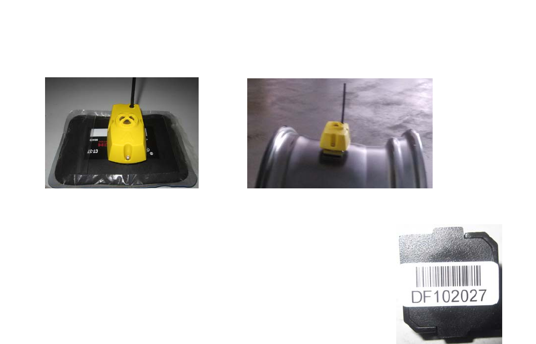
• Before installation, make sure you identify each pair of transmitter and ID
module. We have two installation methods: magnetic installation method and patchy
installation method. For magnetic installation method, there is a pair of transmitters
& ID modules along with two magnets packed in a small box, they have the same ID
code. For patchy installation method, there is also a pair of transmitters & ID
modules along with a patch packed in a small box, they have the same ID code. For
example: DF102027.
Install the transmitter in the wheel with magnets or patch. Then install the ID
modules in the corresponding position of display and trailer ID box.
1.3.1 Installation Transmitter
1.3.1.1 Remove the wheel from the vehicle and then remove the tire. Clean the area where
the transmitter is to be installed.
1.3.1.2 Installation the transmitter
4
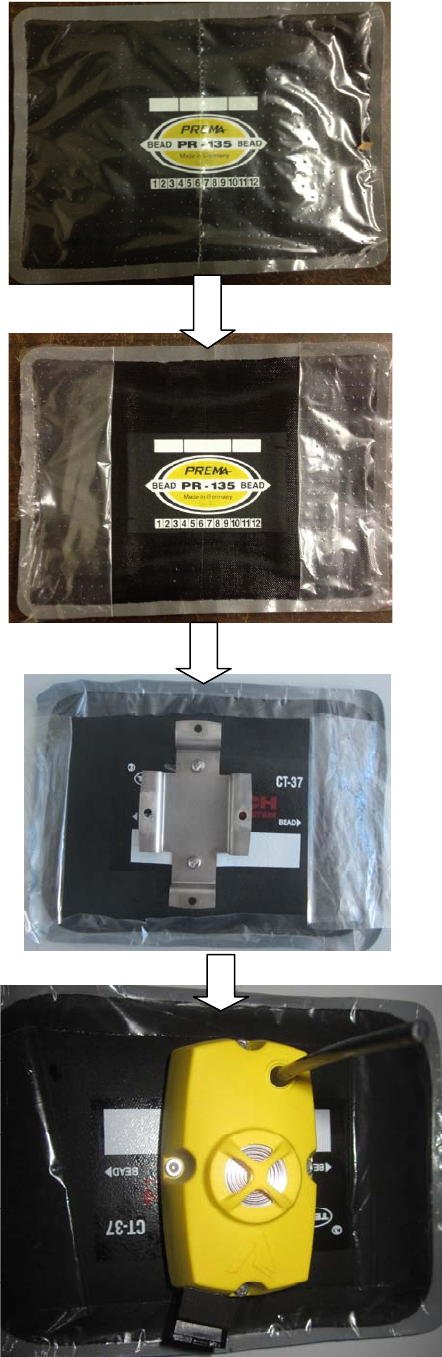
1> Patchy installation method
Carefullycuttheplasticcoverwithoutcuttingthepatch
5
Oncethesensoriscorrectlyinplacewiththemountingholeslinedupwiththe
mountingbracket,replacethescrewstosecurethesensortothemounti:
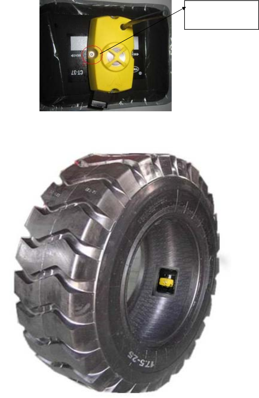
The final installation is shown in the following picture:
Mounting hole and
Mounting screw
6
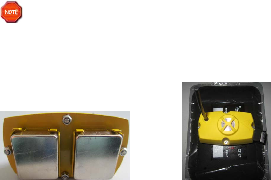
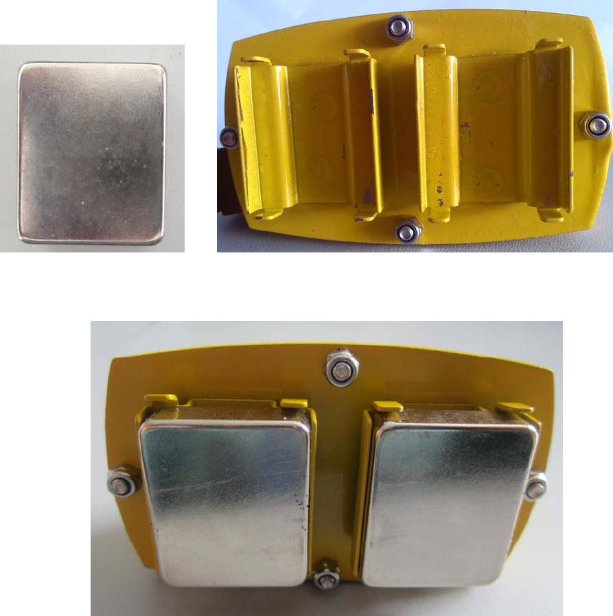
2> Magnetic Installation Method
Clean the magnets and the bottom of the sensor:
Insert the two magnets into the frame of the sensor’s bottom:
Take the rubber cover of the tire and then attach the sensor (shown as in the following
picture) to the rim:
7
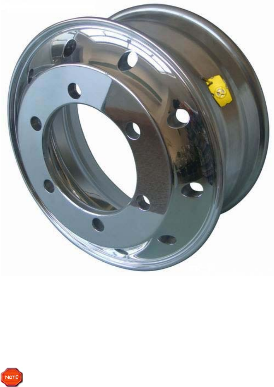
NOTE: The transmitter must be positioned in the lowest spot possible and installed
beside the tire valve in order to know its approximate location after the tire has been
mounted.
NOTE: When fixing the transmitter on the rim, make sure the section of steel strap
installed through the transmitter is complete NOT TOOTHED.
1.3.1.3 Mount the tire on the rim, inflate tire to standard cold inflation pressure specified on
tire sidewall and dynamic balance the wheel before it is put back on the vehicle.
Ensure that the tire beads and mounting hook do not touch the transmitter
during mounting. Pay attention to the transmitter antenna not be clamped by tire
bead and broken by mounting hook. DO NOT inflate tire higher than maximum
pressure stamped on tire sidewall.
1.3.1.4 Use the same procedure to install the other transmitters. And record all ID numbers
labeled on the rim in the Annex table so that you can attach the ID modules to the proper
location.
8
1.3.2 Installation ID Module
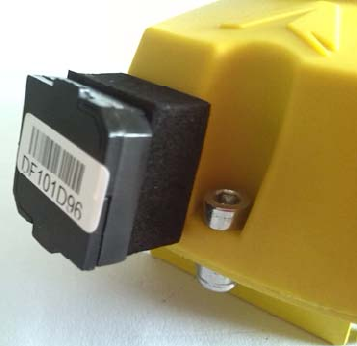
As it’s shown in the picture, the ID module is pasted on the transmitter for convenient
installation. Every ID module has a unique ID number like
DF101D96; this number is only accordant with the attached
transmitter.
When installing the ID module, remove it from the
transmitter and then insert the ID module to the display.
Use the same procedure to install the other ID modules
and make sure your installation is correct.
1.3.3 Removing Transmitter
1.3.3.1 Deflate the tire and remove the wheel weights from the rim. Push the tire bead away
from the rim. Make sure to always set the bead breaker at least 90 degrees from the valve
stem to avoid damaging the transmitter.
1.3.3.2 Firmly fix the wheel on the turntable clamps. (If the mounting head of the tire
changer is positioned at 12 o'clock, then the valve stem should be at the 11 o'clock position.)
Apply lubricant to both tire bead and rim, and then demount the upper tire bead。
1.3.3.3 Use the same procedure to demount the lower tire bead. (If the mounting head of
the tire changer is at the 12 o'clock position, then the valve should also be at the 12 o'clock
position.)
1.3.3.4 Final inspection: Visually inspect the rim and transmitter to ensure no damage has
occurred.
1.4 PARAMETERS OF THE PRODUCTS
Transmitter
Weight: 123g (4.34 oz.)
Dimensions: 8.3 x 4.9 x 3.4 cm (3.27x1.93x1.34 inch)
Operating Temperature Range: -40°C to 85°C (-40°F to 185°F)
Pressure Accuracy: ±0.04 Bar / 0.58PSI (at 0°C ~85°C)
Temperature Accuracy: ± 3°C /5.4 °F(at -20℃~70℃) ,± 5°C /9 °F(-40℃~20℃、70℃~100℃)
Battery Life: 5years at 20 hours driving per day
Maximum Range: 14Bar (203PSI)
Frequency: 433.92MHz
9
1.5 FCC's authentication announcement
This device complies with part 15 of the FCC rules and Industry Canada licence-exempt
RSS standard(s). Operation is subject to the following two conditions (1) this device may
not cause harmful interference, and (2) this device must accept any interference received,
including interference that may cause undesired operation.
This equipment has been tested and found to comply with the limits for a Class B digital
device, pursuant to Part 15 of the FCC Rules. These limits are designed to provide
reasonable protection against harmful interference in a residential installation. This
equipment generates uses and can radiate radio frequency energy and, if not installed and
used in accordance with the instructions, may cause harmful interference to radio
communications. However, there is no guarantee that interference will not occur in a
particular installation. You can test that if this equipment does cause harmful interference to
radio or television reception by turning the equipment off and on.
Caution content: changes or modifications not expressly approved by the party responsible
for compliance could void the user's authority to operate the equipment.
Le présent appareil est conforme aux CNR d'Industrie Canada applicables aux appareils
radio exempts de licence. L'exploitation est autorisée aux deux conditions suivantes : (1)
l'appareil ne doit pas produire de brouillage, et (2) l'utilisateur de l'appareil doit accepter tout
brouillage radioélectrique subi, même si le brouillage est susceptible d'en compromettre le
fonctionnement.
1.6 European regulations announcements
This device complies with all European Electromagnetic compatibility regulations (95/54/EC
and EN300 220-1). The equipment has been tested and found to comply with the above
regulations, and in addition it meets the requirements for low powered
transmitters/receivers as defined by the relevant radio approval authority. The regulations
are designed to provide reasonable protection against harmful interference or susceptibility.
1.7 CE directive announcement
This device complies with the essential protection requirements of Council Directive
89/336/EEC on the approximation of the law of the Member states relating to
electromagnetic compatibility. Operation is subject to the following two conditions: (1) this
device may not cause harmful interference, and (2) this device can accept any interference
received, including interference that may cause undesired operation.