BARCO AMM190WTDSW LCD Color Display User Manual
Advan Int'l Corp. LCD Color Display Users Manual
BARCO >
Users Manual
WiSe™ 19" HDTV
Surgical Display
0240030990
Contents
1 Warnings and Cautions
2 Warnings
2 Cautions
4 About Your Device
4 Intended Use
5 Indications
5 Contraindications
6 Package Content
7 Device Features
10 Setup
10 Connections
12 Basic Video Setup
13 Operation
13 On-Screen Display (OSD)
19 Troubleshooting
21 Periodic Maintenance
21 Cleaning
22 Disposal
23 Technical Specications
27 Symbols

1
Warnings and Cautions
Please read this manual and follow its instructions carefully. e words warning,
caution, and note carry special meanings and should be carefully reviewed:
Warning e personal safety of the patient may be involved. Disregarding this
information could result in personal injury.
Caution Special service procedures or precautions must be followed to avoid
damaging the device.
Note Special information to make maintenance easier or important
information more clear.
An exclamation mark within a triangle is intended to alert the
user to the presence of important operating and maintenance
instructions in this manual.
A lightning bolt within a triangle is intended to warn of the presence
of hazardous voltage. Refer all service to authorized personnel.
e WiSe 19" HDTV Surgical Display has been tested under the UL 60601-1
standard and is UL listed for medical application.
e warranty is void if any of the following warnings or cautions are disregarded.
2
Warnings
To avoid potential serious injury to the user and the patient and/or damage to
this device, please note the following warnings:
• Read this manual thoroughly and
be familiar with its contents prior
to using this device.
• Federal law (United States of
America) restricts this device
to sale by, or on the order of, a
physician.
• Carefully unpack the device and
check if any damage occurred
during shipment.
• is device is non-sterile and
therefore should not be placed in
the sterile eld.
• Do not place the device or any
other heavy object on the power
cord. Damage to the cable can
cause re or electric shock.
• To avoid electric shock, avoid
removing the bezel.
• is device should not be used
adjacent to or stacked with other
devices. If adjacent or stacked use
is necessary, the device should
be observed to verify normal
operation in the conguration in
which it will be used.
• Test this device prior to a surgical
procedure. is device was
fully tested at the factory before
shipment.
• Do not attempt internal repairs
or adjustments not specically
detailed in this manual. Ensure
that readjustments, modications,
and/or repairs are carried out by
persons authorized by Stryker
Endoscopy.
• Do not put any liquid or solid
object into the panel. If this occurs,
unplug the device and have it
checked by qualied personnel
before operating it any further.
• Use appropriate caution to prevent
contact with uids if the device is
being used with a power supply in
patient environments.
• e use of cables and/or other
accessories with this device, other
than those specied, may result in
increased emissions or decreased
immunity of this device.
Cautions
• Connect the device to an AC
adapter connected to a hospital
grade power cord ensuring the
power cord is plugged into a
grounded power outlet to achieve
grounding reliability.
• Do not sterilize the device, as
the delicate electronics cannot
withstand this procedure.
• Use only the proprietary surgical
display power supply for the
display. Completely secure the
connection between the DC power
cord and the extension cord.
• Never operate the device
immediately aer transportation
from a cold location to a warm
location.
3
• To connect to an international
power supply, use an attachment
plug appropriate for the power
outlet, as outlined in the "Technical
Specications" section of this
manual.
• Unplug the device if it is not to
be used for an extended period
of time. To disconnect the cord,
unscrew the plug rst, then pull
the cord out by the plug. Never
pull the cord itself.
• Do not expose the device to
moisture or apply liquid cleaners
directly to the screen. Spray the
cleaning solution into a so cloth
and clean gently. For further detail,
refer to the "Periodic Maintenance"
section of this manual.
• Allow adequate air circulation to
prevent internal heat buildup. Do
not place the device on surfaces
(rugs, blankets, etc.) or near
materials (curtains, draperies) that
may block the ventilation slots.
e device is cooled by natural
convection and has no fan.
• Do not touch the patient with
signal input or output connectors.
Equipment with SIP/SOP
connectors should either comply
with IEC60601-1 and/or IEC
60601-1-1 harmonized national
standards or the combination
should be evaluated for safety.
• To ensure electromagnetic
compatibility, refer to the
“Electromagnetic Compatibility”
section of this manual. e WiSe
19" HDTV Surgical Display
(0240030990) must be installed
and operated according to the
EMC information provided in this
manual.
• Pay close attention to the cleaning
instructions in this manual. A
deviation may cause damage.
• Do not install the device
near sunlight, excessive dust,
mechanical vibration, or shock.
• Do not operate with the glass
device screen facing downward.
• Handle the device with care. Do
not strike or scratch the screen.
• Changes or modications not
expressly approved by the party
responsible for compliance could
void the user’s authority to operate
the device.
Note: is device has been tested and
found to comply with the limit for a Class
B digital device, pursuant to Part 15 of
the FCC Rules. ese limits are designed
to provide reasonable protection against
harmful interference in a residential
installation. is device generates, uses,
and can radiate radio frequency energy
and, if not installed and used in accordance
with the instructions, may cause harmful
interference to radio communications.
ere is no guarantee that interference will
not occur in a particular installation, which
can be determined by turning the device
o and on. e user is encouraged to try to
correct the interference by one or more of
the following measures:
• Reorient or relocate the receiving device.
• Increase the separation distance between
the device.
• Connect the device to an outlet on a
circuit dierent from that to which the
other device(s) are connected.
• Consult the manufacturer or eld service
technician for help.
4
About Your Device
e WiSe 19" HDTV Surgical Display (display) is a wide screen LCD surgical
display that can support a maximum resolution of 1080p. e display supports
various video inputs, including digital RGB, analog RGB, serial digital interface
(SDI), component video (YPbPr/RGB), S-video, C-video, and wireless RGB.
e display features an optional WiSe HDTV Transmitter, which allows it to
receive a high-denition video signal over a radio-frequency link (USA and
Canada only).
Intended Use
e WiSe 19" HDTV Surgical Display is intended for video display during
surgical procedures.
5
Indications
is device is indicated for the following surgical procedures:
• General surgery
• General laparoscopy
• Nasopharynogoscopy
• Ear endoscopy
• Sinusocopy
• Plastic surgery wherever
a laparoscope/endoscope/
arthroscope is indicated for use
• Laparoscopic cholecystectomy
• Laparoscopic hernia repair
• Laparoscopic appendectomy
• Laparoscopic pelvic lymph node
dissection
• Laparoscopically assisted
hysterectomy
• Laparoscopic & thorascopic
anterior spinal fusion
• Anterior cruciate ligament
reconstruction
• Knee arthroscopy
• Shoulder arthroscopy
• Small joint arthroscopy
• Decompression xation
• Wedge resection
• Flexible endoscopy
• Urology
• Gynecology
• Lung biopsy
• pleural biopsy
• Dorsal sympathectomy
• Pleurodesis
• Internal mammary artery
dissection for coronary artery
bypass graing where endoscopic
visualization is indicated and
examination of the evacuated
cardiac chamber during
performance of valve replacement
e indicated users of this device are as follows:
• General surgeons
• Gynecologists
• Cardiac surgeons
• oracic surgeons
• Plastic surgeons
• Orthopedic surgeons
• ENT surgeons
• Urologists
e display is a non-sterile, reusable device not intended for use in the sterile
eld. e display is intended for use by qualied physicians having complete
knowledge of these surgical procedures.
Contraindications
ere are no known contraindications for this device.
6
Package Content
1
2
4
35
Package Content Part Number
1. WiSe 19" HDTV Surgical Display 240-030-990
2. (4) M4 × 10 mm VESA screws –
3. Hospital-grade AC power cord (USA and Canada only) –
4. WiSe 19'' Surgical Power Supply 240-030-992
5. Cable Cover –
Optional Accessories Part Number
WiSe HDTV Transmitter (USA and Canada only) 240-030-971
15-. (5 pin) DC extension cable 240-030-951
75-. (5 pin) DC extension cable 240-030-952
WiSe 19" Display Cover 240-030-991
Hospital-grade AC power cord (USA and Canada only) 105-033-001
7
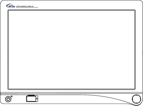
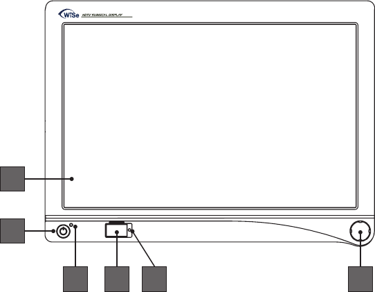
Device Features
Front panel
Operate the display using the rotary control located on the front panel. A list
of the display controls and their functions is provided below.
1
3 4 65
2
1. Display Screen Shows video image.
2. Power switch (so) Powers the display ON and OFF.
3. Power LED Indicates current status. Shines green if the
display is powered on or is in screen saver mode;
blinks red if the display is in standby mode;
blinks amber if over voltage.
4. Token slot Token insertion site used to establish a wireless
connection with the transmitter (optional for
USA and Canada only).
5. Token LED Provides feedback when linking the display and
transmitter (optional for USA and Canada only).
6. Rotary control Accesses the on-screen display and navigates
through its functions.
8
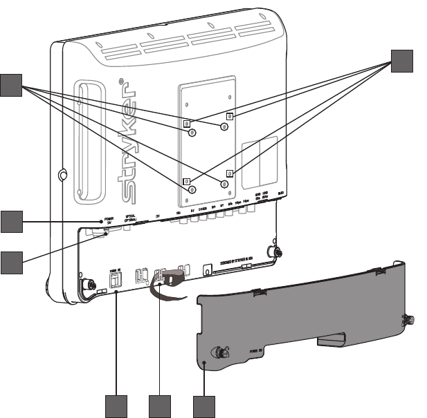
Rear panel
5 6
4
3
1
7
2
1. VESA mounting holes
(75mm)
Provide access points for mounting the
display.
2. VESA mounting holes
(100mm)
Provide access points for mounting the
display.
3. Connector labels Indicate the types of video connectors.
4. Power connector Connects to the 13V DC power supply.
5. Power switch (hard) Powers the input DC power ON and OFF.
6. Cable-management
Velcro Straps
Organize cables (3 straps included).
7. Cable-management cover Covers cables.
9
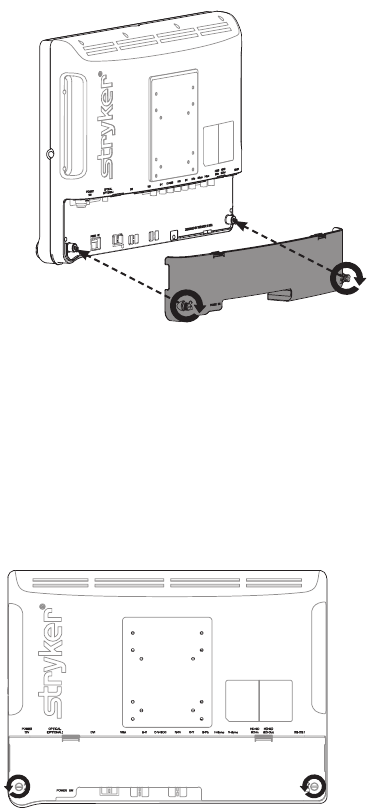
Cable Cover
Installing the Cable Cover
1. Align the le and right hinges of the cable cover onto the bottom rear
of the display.
2. Snap on the top section of the cable cover to the aligning clips.
3. With your ngers, turn the thumbscrews clockwise to tighten and lock
the cable cover onto the display.
Uninstalling the Cable Cover
1. With your ngers, turn the thumbscrews counter clockwise to loosen.
2. Once the thumbscrews are completely loosened, pinch the le and
right clips and pull the cable cover towards you.
3. Remove the cable cover o the le and right hinges.
10
Setup
Stryker Endoscopy considers instructional training, or inservice, an integral part
of this device. Your local Stryker Endoscopy sales representative will perform at
least one inservice at your convenience to help set up your device and instruct
you and your sta on its operation and maintenance. To schedule an inservice,
contact your local Stryker Endoscopy representative aer your device has
arrived.
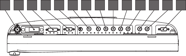
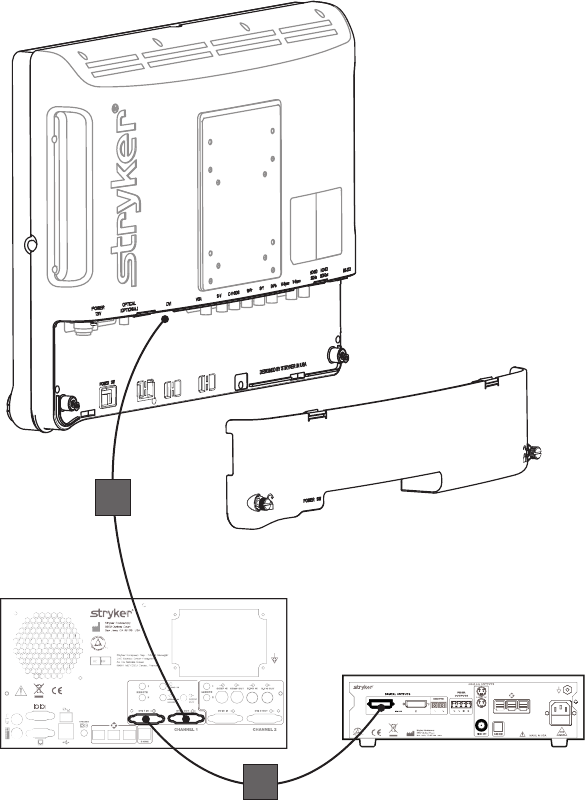
Connections
Connection Ports
Video input signals are connected to the rear of the display, as illustrated
below:
1 2 3 4 5 141312116 7 8 9 10
1. Power 13V
2. Non-Functional
3. DVI
4. VGA
5. S-Video
6. C-Video/SOG
7. R/Pr
8. G/Y
9. B/Pb
10. H-sync
11. V-sync
12. HD/SD SDI IN
13. HD/SD SDI OUT
14. RS232
11
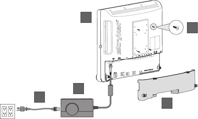
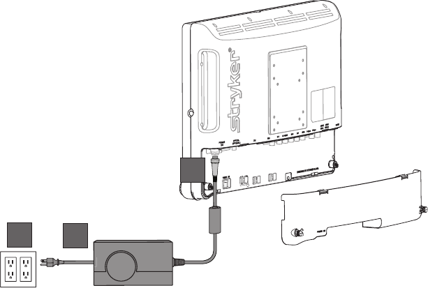
Connecting the WiSe 19" Surgical Display Power Supply
1
2
3
1. Connect the power supply to the 13V input on the display.
2. Connect the power cord to the power supply.
3. Connect the AC power, using the supplied hospital-grade power cord.
4. (Optional, not shown) Connect an extension cord between the power
supply and display.
5. Install cable cover.
12
Basic Video Setup
WiSe 19" HDTV Surgical Display
SDC
Camera
1
2
1. Ensure the cable cover has been removed.
2. Route the video output 1 from the camera to the SDC.
3. Route the video output 1 from the SDC to input on the DVI input on the
display.
4. Reinstall the cable cover.

13
Operation
Operate the display using the rotary control located on the front panel. A list of
the display controls and their functions is provided below.
On-Screen Display (OSD)
Accessing the On-Screen Display
To access the OSD, use the Rotary Control as outlined below:
• Turn Right/Le — With the on-screen display menu activated, turning
increases/decreases the value of the selected parameter. With the on-screen
display deactivated, turning activates the video source selection menu.
• Push — Accesses/selects on-screen display menu.
• Push and Hold — Exits on-screen display menu.
Operating On-Screen Display
e device OSD helps navigate through various device menus.
1. Press the Rotary Control to activate the OSD menu.
2. Rotate the Rotary Control to move up or down through the menu.
e parameter will be highlighted when selected.
3. Press the Rotary Control to enter the next level OSD.
4. Rotate the Rotary Control to increase or decrease the value of the selected
parameter, or to make a selection on dierent options.
5. To exit the OSD menu screen from the second — or third — level OSD
menu, select the Exit option. To completely exit the OSD, press and hold
the Rotary Control. If no keys are pressed, the OSD will automatically exit
aer the factory-set predetermined time (the time is customizable).
6. While the OSD menu is deactivated, rotate the Rotary Control to activate
the input signal selection menu. e current input signal will be indicated
by a dot. Rotate the Rotary Control to select the preferred input signal.
Input Selection List
• Digital RGB • HD/SD-SDI • C-Video
• Analog RGB • SOG • Wireless RGB
• S-Video • RGBS • Exit
• Component (Y/Pb/Pr)

14
OSD Menus
Speciality
Menu Item Description Range
Color Temperature* Chooses between
color temperatures for
Standard, Arth, Lap,
PACS, or Norm
—
Red Red balance -128–127
Green Green balance -128–127
Blue Blue balance -128–127
Gamma Gamma value 0.1–2.5, S0, S1, S2
Setting
Menu Item Description Range
Brightness Increases or decreases the
brightness 0–100
Contrast Increases or decreases the
contrast 0–100
Phase** Increases or decreases the
Phase level 0–100
Chroma** Increases or decreases the
Chroma level 0–100
Image Sharpness Sets image sharpness 1–10
Video Sharpness** Increases or decreases the
video sharpness 0–100
* Color Temperature RGB adjustment is available only for Standard, Arth, and Lap settings.
PACS and Norm adjustments are only avaliable under SOG input.
** Only available under SDI-, S-, or C-video input.

15
Image Effect
Menu Item Description
Scale Mode Chooses scale mode between Fill All, V-Fill,
H-Fill, One-To-One, or Fill-Aspect
Freeze Frame Enables or disables freeze frame
PIP Enables PIP (picture in picture) function
POP Enables POP (picture on picture) function
PBP Enables PBP (picture by picture) function
Advanced
Menu Item Description
Key Lock Sets to key lock mode
Auto Source Select Adjusts Auto Source Select between on and o
DPMS Chooses DPMS (display power
management signaling)
OFF, 30, 60, 90,
or 120min
OSD Control Controls OSD Menu Position, Background, and
Time out
Restore Factory
Settings
Sets to factory default
Screen Control*** Controls and adjusts Horizontal, Vertical,
Frequency, and Phase
*** Only available under analog inputs under certain respective inputs.
Wireless Module (for the USA and Canada only)
Status Description
RX MAC: XXXXXXXX
RX SW: vXX.XX.XX
Receiver
TX MAC: XXXXXXXX
TX SW: vXX.XX.XX
SIGNAL: Excellent, Good, Poor
REGIONLAL SETTING: XXXXXXXX
CHANNEL XXXX MHz
Transmitter

16
Information
Menu Item Description
User Name Entry Enters custom user name display for boot-up
display
Serial Number Displays device serial number
Runtime Displays current device total run time
Input Format Displays current input format
Note: Actual on-screen display values may vary with updated versions of the rmware and user
settings.
17
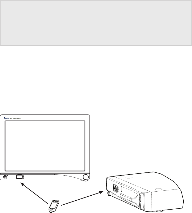
Linking Transmitter to Auxiliary Display (for USA and
Canada Only)
Temporary Linking
Caution Equipment that employs RF communications may aect
the normal function of the transmitter. When choosing a
location for the transmitter, consult the “Electromagnetic
Compatibility” section of this manual to ensure proper
function.
e transmitter functions in the 4.9 – 5.9 GHz spectrum. As necessary,
remove or recongure other wireless devices from the environment, such
as cordless phones and 802.11a/n routers to make channels available for the
transmitter and display.
To link the display to the transmitter and thereby enable wireless
communication, any blue WiSe HDTV Transmitter token will suce.
1. Power on the transmitter and auxiliary display. e token LED shines
amber as the units perform startup functions.
2. Insert the token into the token slot on the transmitter. e token LED
continues to shine amber as it writes the data.
3. When the token LED turns green, remove the token from the transmitter.
4. Within 2 minutes, insert the token into the token slot on the auxiliary
display. An audible tone will sound from the transmitter and the token
LED will change from amber to green when the display and transmitter
have been linked.
18
5. Remove the token from the token slot on the auxiliary display.
6. By repeating steps 4 and 5, as many as two additional auxiliary displays
may be linked. All linking must be done within two minutes.
7. Store the token in the transmitter token slot when not in use.
Note: If multiple transmitters are within 100 feet of each other, for example, inadjacent
operating rooms, link each transmitter to its respective display(s) one set at a time. Wait 15
seconds before linking the next transmitter/display set.
Permanent Linking
Please contact your Stryker rep in order to permanently link the display(s)
with a specic transmitter, as deemed appropriate. A permanent link may
be desirable in certain cases. Once the display(s)/transmitter set has been
permanently linked, the set will automatically link when powered on.
Display(s)/transmitter sets that have been set to permanent link mode should
be kept in the same operating room.
To return the display(s)/transmitter set to default linking mode please follow
the instructions below using a blue WiSe Linking Token.
1. Power on the display(s) and transmitter.
2. Insert the blue token into the transmitter and remove it when the token
LED turns green.
3. Insert the blue token into each display, one at a time, and remove the token
when the token LED turns green.
4. Power o all devices.
5. Power on all devices.
Now the system can be linked as described in the default linking mode
procedure.

19
Troubleshooting
Before returning your display for service, consult the troubleshooting list below:
Display
Problem Current Status Remedy
No picture Power LED on Using the OSD Menu, adjust
the brightness and contrast to
maximum, or reset them to their
default settings.
Power LED o Ensure the power switch at the
front and rear of the display are set
to ON.
Check if the AC power cord is
properly connected to the AC
adapter and outlet.
Power LED
blinking
Check if the video signal cable
isproperly connected at the back
ofthe display.
Check if power of the video signal
source system is ON.
Abnormal
picture
Oversized,
undersized,
ormissing
display; or
center shi.
Using the Screen Control Menu,
adjust the Phase, Frequency,
Horizontal, and settings in order
to correct the display image.
Wait a few seconds aer initial
sync of video signals, or power
cycle the display.
OSD Menu
error message
“Video format
notsupported”
Ensure that an acceptable video
source is connected. Refer to
the "Technical Specications"
section of this manual for a list
ofacceptable video formats.

20
Optional Transmitter (for the USA and Canada Only)
Problem Current Status Remedy
Wireless link
not established
within 2
minutes (with
optional
WiSe HDTV
transmitter).
“Wireless RGB
NoSignal”
Cycle the hard power switch at the
rear of the display. Cycle the hard
power switch at the front of the
transmitter.
Wireless link
established
with some but
not all displays
(with optional
WiSe HDTV
transmitter).
“Wireless RGB
NoSignal”
Cycle the hard power switch on
the aected display only. Re-insert
the token into the display.
Transmitter
token LED
blinks amber
No channels
available for
WiSe System
Remove or recongure other
wireless devices from the
environment, such as cordless
phones and 802.11 a/n routers,
tomake channels available for
thedisplay and transmitter.

21
Periodic Maintenance
Caution Do not expose the display to moisture or apply liquid
cleaners directly to the display screen. Spray the cleaning
solution into a so cloth and clean the screen gently.
Cleaning
1. Disconnect the display from the power supply before cleaning.
2. Clean the plastic areas of the display with a dry, so cloth, or a so cloth
lightly moistened with mild detergent solution. Do not use any type of solvent,
such as alcohol or benzine, which might damage the nish. Recommended
cleaning agents for bezel cleaning based on testing include:
• Cidex (2.4% glutaraldehyde solution)
• 0.5% Chlorhexidine in 70% isopropyl alcohol
3. Clean the display screen with a dry, so cloth, or so cloth lightly moistened
with warm water. Other acceptable cleaning agents are listed below:
• 70% isopropyl alcohol
• Cidex (2.4% glutaraldehyde solution)
• 0.5% Chlorhexidine in 70% isopropyl alcohol
4. Dry thoroughly with a so towel or gauze surgical sponge.
Before using a cleaning agent not listed, ensure that the respective agent is
validated in order to assure durability of the cleanability of the device. To validate
the agent, a cleaning process repeated 104 times needs to be conducted with the
respective cleaning agent. is cleaning process includes using the prospective
cleaning agent, moistening a cloth or sponge, and wiping the front and sides of
the console.
A visual check incorporating the following is used to ensure compatibility:
• e device should still function appropriately
• e device nish should not discolor or scratch
• e device nish should not dissolve or rub o
• e device labeling should still be legible
ese validation steps need to be performed in order to validate any and all
cleaning agents outside of those listed.

22
Disposal
is product contains electrical waste or electronic equipment. It must
not be disposed of as unsorted municipal waste and must be collected
separately in accordance with applicable national or institutional
related policies relating to obsolete electronic equipment.
Dispose of any system accessories according to normal institutional practice
relating to potentially contaminated items.
23
Technical Specifications
Display
LCD Display Panel 18.95"(481.33mm)Diagonal
(a-Si TFT active matrix LCD)
Synchronization 2.5 – 5.0Vppseparated sync
Pixel Pitch 0.2835(H)×0.2835(V)mm
Response Time <5msTyp
Viewing Angle Right/Left80(Typ)
Up75(Typ),Down85(Typ)
Display Colors 16.7millioncolors
Native Resolution 1440(H)lines×900(V)lines
Input Signal 1DVI, 1VGA, 1HD/SD-SDI, 1C-Video/SOG, 1S-Video,
1Component (Y/G, Pb/B, Pr/R, H, VS), 1Wireless
Maximum Pixel Clock 160MHz
Electrical
Power Adapter
Power Consumption
Current
100–240VAC;13VDC
90W(max)
Direct
Current/Voltage Rating
Please ensure the respective power cord complies with applicable local regulations and standards.
110V +/- 10V power outlets Select a power supply cord that is UL Listed and C.S.A Certied,
type SJT or SVT, 3 – conductor, 18AWG, terminated in a molded
on hospital grade plug cap rated 110V+/-10V, 15A, with a
minimum length of six feet.
220V +/- 20V power outlets Select a power supply cord that is internationally harmonized
and marked “<HAR>”, 3 – conductor, 0.75 mm^2 minimum
wire, rated 220V+/-20V, 10A with a PVC insulated jacket. e
cord must have a molded on plug cap rated 220V+/-20V,10A.
e cord and plug cap must be suitable for medical use.
Dimensions
Dimensions (W × H × D) 462.3×340.8×106.7mm
18.2×13.4×4.2in
Weight (approximate) 5.8kg;12.79lbs.
VESA Mounting Interface VESA100×100mm
VESA75×75mm
Operating Conditions
Operating Temperature
Relative Humidity
Electrical Input Rating
41 – 104°F (5 – 40°C)
30 – 95%
13V DC 6.92A

24
Transport & Storage Conditions
Storage
Relative Humidity Range
-0.4 – 140°F (-18 – 60°C)
10 – 85%
Classication and Approvals
Class I Equipment
Medical equipment with respect to electric shock, re, and mechanical hazards only in
accordance with UL 60601-1 and CAN/CSA C22.2 No.601.1.
IPX1 Water Ingress Protection
Continuous Operation
Compliance
Medical Safety Standards IEC 60601-1:1988 + A1:1991 + A2:1995
CAN/CSA C22.2 No 601.1-M90
UL 60601-1:2003
AS/NZS 3200.1.0:1998
CSA 22.2.601.1.1:2002
Medical EMC Standard IEC 60601-1-2:2007
FCC Regulations FCC Part 15 Class B
FCC Identier: QVXAMM190WTDSW
IC Regulations IC: 7680A-AMN12100 (WiSe 19" and 26" HDTV Surgical
Display)
Note: Please contact your local Stryker Endoscopy sales representative for information on changes
and new products.
Electromagnetic Compatibility
Like other electrical medical equipment, the WiSe™ 19" HDTV Surgical Display requires special
precautions to ensure electromagnetic compatibility with other electrical medical devices. To
ensure electromagnetic compatibility (EMC), the display must be installed and operated according
to the EMC information provided in this manual. e display has been designed and tested to
comply with IEC 60601-1-2:2001 requirements for EMC with other devices.
Warning
When this device is connected with other electrical equipment, leakage
currents may be additive. To minimize total leakage current per patient,
ensure that all systems are installed according to the requirements of IEC
60601-1-1.
Caution Portable and mobile RF communications equipment may aect the normal
function of the display.
Do not use cables or accessories other than those provided with the display,
as this may result in increased electromagnetic emissions or decreased
immunity to such emissions.
If the display is used adjacent to or stacked with other equipment, observe
and verify normal operation of the display in the conguration in which
it will be used prior to using it in a surgical procedure. Consult the tables
below for guidance in placing the display.

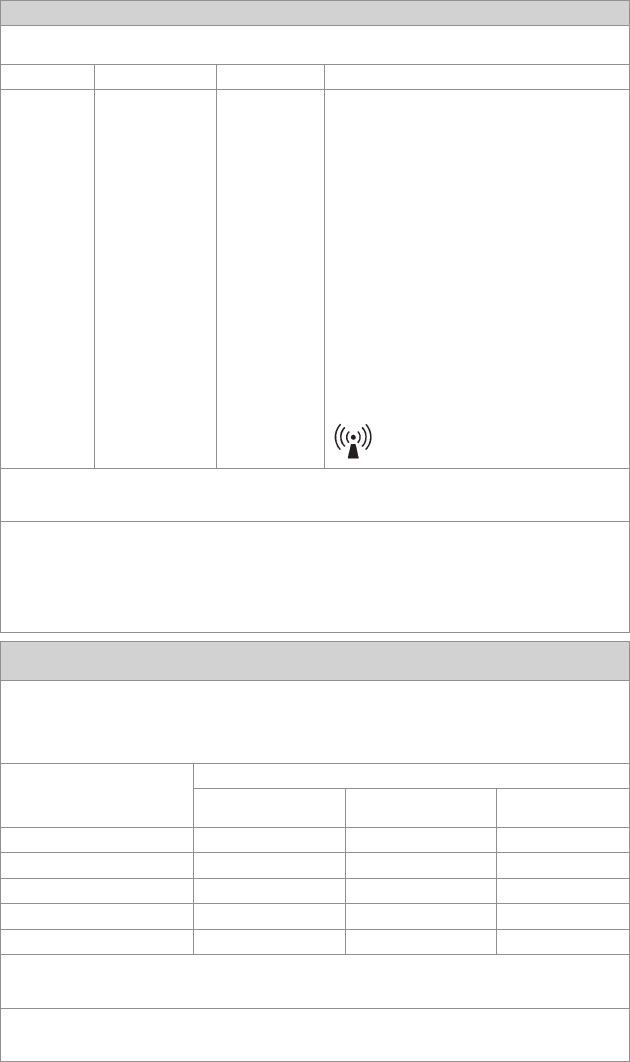
25
Guidance and Manufacturer’s Declaration: Electromagnetic Emissions
e WiSe™ 19" HDTV Surgical Display is intended for use inthe electromagnetic environment specied below. e customer or
the user of the WiSe™ 19" HDTV Surgical Display should ensure it is used in such an environment.
Emissions test Compliance Electromagnetic Environment - guidance
RF emissions CISPR 11 Group 1 e WiSe™ 19" HDTV Surgical Display uses RF energy only for its
internal function; therefore, its RF emissions are very low and are not
likely to cause any interference in nearby electronic equipment.
RF emissions CISPR 11 Class B e WiSe™ 19" HDTV Surgical Display is suitable for use in all
establishments other than domestic establishments and those directly
connected to the public low-voltage power supply network that
supplies buildings used for domestic purposes, provided the following
warning is heeded:
Warning: is system is intended for use by health care professionals
only. is system may cause radio interference or may disrupt the
operation of nearby equipment. It may be necessary to take mitigation
measures, such as reorienting or relocating the system or shielding
the location.
Harmonic emissions IEC61000-3-2 Class D
Voltage Fluctuations/ icker
emissions IEC61000-3-3
Complies
Guidance and Manufacturer’s Declaration — Electromagnetic Immunity
e WiSe™ 19" HDTV Surgical Display is intended for use in the electromagnetic environment specied below. e customer or
the user of the WiSe™ 19" HDTV Surgical Display should ensure that it is used in such an environment.
Immunity Test IEC 60601 Test Level Compliance Level Electromagnetic Environment--
Guidance
Electrostatic
Discharge (ESD)
IEC61000-4-2
6kV contact
8kV air
6kV contact
8kV air
Floors should be wood, concrete,
or ceramic tile. If oors are
covered with synthetic material,
the relative humidity should be
at least 30%.
Electrical fast
transient/burst
IEC61000-4-4
2kV for power supply lines
1kV for input/output lines
2kV line to ground
1kV line to line
Mains power quality should be
that of a typical commercial or
hospital environment.
Surge
IEC61000-4-5
1kV dierential mode
2kV common mode
1kV dierential mode
2kV common mode
Mains power quality should be
that of a typical commercial or
hospital environment
Voltage dips, short
interruptions and
voltage variations on
power supply input
lines
IEC61000-4-11
• <5% Ut (>95% dip in Ut)
for 0.5 cycle
• 40% Ut (60% dip in Ut) for
5 cycles
• 70% Ut (30% dip in Ut) for
25 cycles
• <5% Ut (>95% dip in Ut)
for 5 sec.
• <5% Ut (>95% dip in Ut)
for 0.5 cycle
• 40% Ut (60% dip in Ut) for
5 cycles
• 70% Ut (30% dip in Ut) for
25 cycles
• <5% Ut (>95% dip in Ut)
for 5 sec
Mains power quality should be
that of a typical commercial or
hospital environment. If the
user of the transmitter requires
continued operation during
power mains interruptions, it is
recommended that the Wireless
Transmitter be powered from an
uninterruptible power supply or
a battery.
Power frequency
(50/60Hz) magnetic
eld
IEC 61000-4-8
3.0 A/m 3.0 A/m Power-frequency magnetic elds
should be at levels characteristic
of a typical location in a
typical commercial or hospital
environment.
Note: Ut is the AC mains voltage prior to application of the test level.
26
Guidance and Manufacturer’s Declaration: Electromagnetic Immunity
e WiSe™ 19" HDTV Surgical Display is intended for use in the electromagnetic environment specied below.
e customer or the user of the WiSe™ 19" HDTV Surgical Display should ensure that it is used in such an environment.
Immunity Test IEC 60601 Test level Compliance Level Electromagnetic Environment - Guidance
Portable and mobile RF communications equipment
should be used no closer to any part of the WiSe 19"
HDTV Surgical Display, including its cables, than the
recommended separation distance calculated from the
equation applicable to the frequency of the transmitter.
Recommended Separation Distance:
Conducted RF
IEC 61000-4-6
3 Vrms
150 kHz to 80 MHz
3 V d = 1.17√P
Radiated RF
IEC 61000-4-3
3 V/m
80MHz to 2.5 GHz
3 V/m d = 1.17√P 80 MHz to 800 MHz
d = 2.33√P 800 MHz to 2.5 GHz
where P is the maximum output power rating of the
transmitter in watts (W) according to the transmitter
manufacturer and d is the recommended separation
distance in meters (m).
Field strengths from xed RF transmitters, as determined by
an electromagnetic site survey (a), should be less than the
compliance level in each frequency range(b).
Interference may occur in the vicinity of equipment marked
with the following symbol:
NOTE 1: At 80 MHz and 800 MHz, the higher frequency range applies.
NOTE 2: ese guidelines may not apply in all situations. Electromagnetic propagation is aected by absorption and reection
from structures, objects, and people.
(a) Field strengths from xed transmitters, such as base stations for radio (cellular/cordless) telephones and land mobile radios,
amateur radio, AM and FM radio broadcast, and TV broadcast, cannot be predicted theoretically with accuracy. To assess the
electromagnetic environment due to xed RF transmitters, an electromagnetic site survey should be considered. If the measured
eld strength in the location in which the WiSe™ 19" HDTV Surgical Display is used exceeds the applicable RF compliance
level above, the display and transmitter should be observed to verify normal operation. If abnormal performance is observed,
additional measures may be necessary, such as reorienting or relocating the WiSe™ 19" HDTV Surgical Display.
(b) Over the frequency range 150 kHz to 80 MHz, eld strengths should be less than 3 V/m.
Recommended Separation Distances Between Portable and Mobile RF Communications Equipment and the WiSe™ 19"
HDTV Surgical Display
e WiSe™ 19" HDTV Surgical Display is intended for use in an electromagnetic environment in which radiated RF
disturbances are controlled. e user of the WiSe™ 19" HDTV Surgical Display can help prevent electromagnetic interference
by maintaining a minimum distance between portable and mobile RF communications equipment (transmitters) and the
WiSe™ 19" HDTV Surgical Display as recommended below, according to the maximum output power of the communications
equipment.
Rated maximum output power (W)
of transmitter
Separation distance (m) according to frequency of transmitter
150 kHz to 80 MHz
d = 1.17√P
80 kHz to 800 MHz
d = 1.17√P
800 kHz to 2.5 GHz
d = 1.17√P
0.01 0.12 0.12 0.23
0.1 0.37 0.37 0.74
1 1.17 1.17 2.33
10 3.70 3.70 7.37
100 11.70 11.70 23.30
For transmitters rated at a maximum output power not listed above, the recommended separation distance (d) in meters (m)
can be estimated using the equation applicable to the frequency of the transmitter, where P is the maximum output power rating
of the transmitter in watts (W) according to the transmitter manufacturer.
Note 1: At 80 MHz and 800 MHz, the separation distance for the higher frequency range applies.
Note 2: ese guidelines may not apply in all situations. Electromagnetic propagation is aected by absorption and reection
from structures, objects, and people.
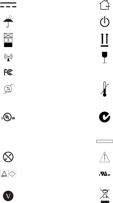
27
Symbols
e following symbols appear on the product, its labeling, or the product
packaging. Each symbol carries a special denition, as dened below:
Direct Current For Indoor Use Only
Do Not Get Device Wet DC Power Control Switch
Maximum Stacking is Side Up
Wireless Transmission Fragile
Tested to comply with FCC
Class B standards IPX1 Degrees of protection against the
ingress of water
Operating Humidity Ratings Operating Temperature Ratings
Medical Equipment is in
accordance with UL 60601-1
and CAN/CSA C22.2 No. 601.1
in regards to electric shock,
re hazards, and mechanical
hazards.
is symbol indicates that this
product is compliant to applicable
standards and is suitable for the
Australian market.
IC Industrial Canada MADE IN KOREA Made in Korea
No Servicable Parts Refer to Instructions
Japan PSE Mark Denan UL Functional Safety Recognized
Component
Eciency Level
is product contains waste
electrical or electronic equipment. It
must not be disposed of as unsorted
municipal waste and must be
collected separately.
Stryker Endoscopy
5900 Optical Court
San Jose, CA 95138 USA
1-408-754-2000, 1-800-624-4422
www.stryker.com
European Representative:
Regulatory Manager, Stryker France
ZAC Satolas Green Pusignan
Av. De Satolas Green
69881 MEYZIEU Cedex, France
Stryker Corporation or its divisions or
other corporate aliated entities own,
use or have applied for the following
trademarks or service marks: WiSe and
the Stryker logo. All other trademarks
are trademarks of their respective
owners or holders.
P16023 A
2011/04