BARCO AMM215MPWTD LCD Color Medical Monitor User Manual
Advan Int'l Corp. LCD Color Medical Monitor
BARCO >
User manual
AUTO - SCANNING WITH DIGITAL CONTROL
LCD COLOR MEDICAL MONITOR
AMM215MPWTD
Operation Manual
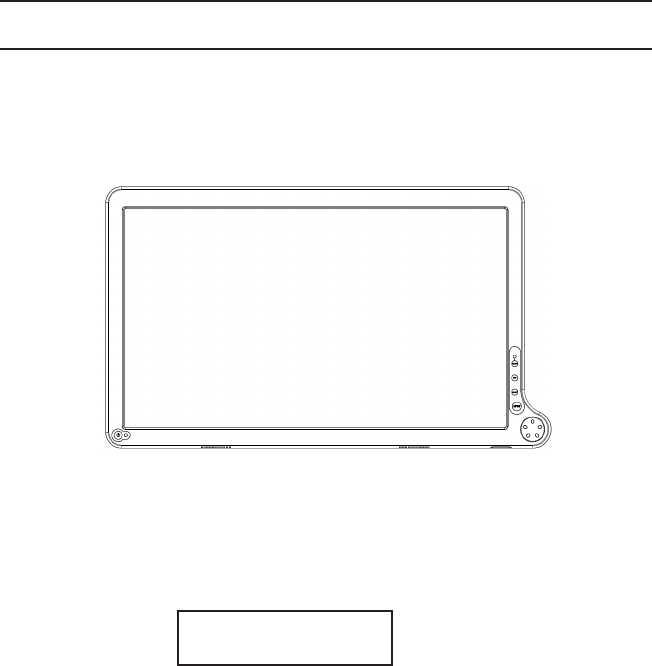
For future reference, record the serial number of your display
monitor in the space below :
Serial Number
The serial number is located on the back of the monitor
back of the monitor
ADVAN INT’L CORP.2013
All other trademarks are the property of their reference owners.
This document is subject to change without notice.
Advan provides this information as reference only. Reference to other vendor’s
products does not imply any recommendation or endorsement.
Revision Control
WARNING
The title «WARNING» is used to inform the users of pos-
sible causes that could inict the injury, death, or property
damage to the patients.
CAUTION
The title «CAUTION» is used to inform the users of pos-
sible causes that could inict the patients although it might
not severe enough to cause deaths.
NOTE
The title «NOTE» is used to inform the users of items that
are of importance in terms of installation, operation, or
maintenance of the Equipment although the failure does
not inict the bodily harm to the patients.
Document Number
Rev. A
AMM215MPWTD 1
ENGLISH

TABLE OF CONTENTS
Product Description and Intended Use ......................................................
Warnings and Cautions .............................................................................
Symbol Explanations .................................................................................
EU Declaration of Conformity for Medical Applications .............................
Safety Precaution ......................................................................................
Cleaning Your Monitor ...............................................................................
Recommendation to Use more than One Unit...........................................
On Burn-in .................................................................................................
Power Management Function....................................................................
Preset Modes..............................................................................................
Video Signals .............................................................................................
PIP / POP / PBP function...........................................................................
DDC ...........................................................................................................
Monitor Installation ....................................................................................
PCoIP Installation ......................................................................................
Connecting the Power Cord ......................................................................
User Function / Messages.........................................................................
OSD Section ..............................................................................................
Troubleshooting .........................................................................................
Specication of (AMM215MPWTD) ...........................................................
Classication .............................................................................................
Electromagnetic Compatibility ...................................................................
Dimension Drawing (mm) of AC Adapter ...................................................
Dimension Drawing (mm) of AMM215MPWTD .........................................
Connectors ................................................................................................
Description of Warranty .............................................................................
Accessory Item List ...................................................................................
3
4
7
8
9
9
9
9
10
11
12
12
13
13
14
15
16
17
25
26
27
28
30
31
32
33
37
2 User’s Guide
Product Description and Intended Use
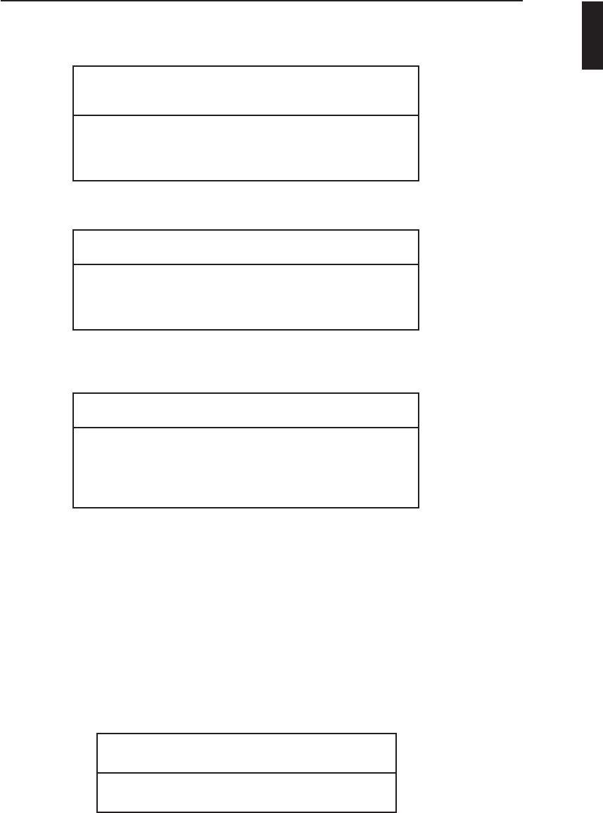
Please check the following items are present when you unpack the box, and save
the packing materials in case you will need to ship or transport the monitor in future.
• AMM215MPWTD LCD Monitor(the equipment that displays information,
graphic data, image and video on its LCD screen) and two video cables
(1) HD15 VGA cable (1) DVI-I cable
• AC Power cord*
• AC-Adapter
• User Manual and 4pcs VESA screws
Cable Cover
*Might vary pending on region standard
CAUTION
Model No : JMW1100KB1300F02
AMM215MPWTD 3
ENGLISH

Warnings and Cautions
Please read this manual and follow its instructions carefully. The words warning,
caution, and note carry special meanings and should be carefully reviewed:
Warning The personal safety of the patient or physician may be
involved. Disregarding this information could result in
injury to the patient or physician.
Caution Special service procedures or precautions must be
followed to avoid damaging the instrument.
Note Special information to make maintenance easier or important
information more clear.
An exclamation mark within a triangle is intended to alert the
user to the presence of important operating and maintenance
instructions in the literature accompanying the product.
A lightning bolt within a triangle is intended to warn of the
presence of hazardous voltage. Refer all service to authorized
personnel.
Warning TO AVOID POTENTIAL SERIOUS INJURY TO THE USER
AND THE PATIENT AND/OR DAMAGE TO THIS DEVICE,
THE USER MUST :
Warranty is void if any of these warnings are disregarded.
ADVAN Int’l Corp accepts full responsibility for the effects on safety, reliability, and
performance of the equipment only if:
• Re-adjustments, modications, and/or repairs are carried out exclusively
by ADVAN Int’l Corp.
• The electrical installation of the relevant operating room complies with the
applicable IEC and CE requirements.
Warning Federal law (United States of America) restricts this
device to use by, or on order of a physician.
The ADVAN Int’l Corp AMM215MPWTD monitor has been tested under UL 60601-1
standard and UL listed for Medical application.
ADVAN Int’l Corp reserves the right to make improvements in the product(s)
described herein. Product(s), therefore, may not agree in detail to the published
design or specications. All specications are subject to change without notice.
Please contact ADVAN Int’l Corp directly or phone your local ADVAN Int’l Corp sales
representative or agent for information on changes and new products.
4 User’s Guide

Warnings
1. Read the operating manual thoroughly and be familiar with its contents prior to using
this equipment.
2. Carefully unpack the unit and check if any damage occurred during shipment.
3. Should any solid object or liquid fall into the panel, unplug the unit and have it checked
by qualied personnel before operating it any further.
4. Uplug the unit if it is not to be used for an extended period of time. To disconnect the
cord, pull it out by the plug. Never pull the cord itself.
5. Be a qualied physician, having complete knowledge of the use of this equipment.
6. Test this equipment prior to a medical procedure. This monitor was fully tested at the
factory before shipment.
7. Avoid removing covers on control unit to avoid electric shock.
8. Attempt no internal repairs or adjustments not specically detailed in this operating
manual.
9. Pay close attention to the care, cleaning instructions in this manual. A deviation may
cause damage (refer to the Cleaning section).
10. DO NOT STERILIZE MONITOR.
11. Read the entire instruction manual before assembling or connecting the camera.
12. Do not place the monitor or any other heavy object on the power cord. Damage to the
cable can cause re or electirc shock.
13. Monitor with power supply is suitable for use in patient environment.
14. DO NOT stack more than 3 boxes high
This equipment has been tested and found to comply with the limits for medical devices in
IEC 60601-1-2:2003. These limits are designed to provide reasonable protection against
harmful interference in a typical medical installation.
This equipment generates, uses and can radiate radio frequency energy and, if not installed
and used in accordance with the instructions, may cause harmful interference to other devic-
es in the vicinity. However, there is no guarantee that interference will not occur in a particular
installation. If this equipment does cause harmful interference to other devices, which can be
determined by turning the equipment off and on, the user is encouraged to try to correct the
interference by one or more of the following measures:
- Reorient or relocate the receiving device.
- Increase the separation between the equipment.
- Connect the equipment into an outlet on a circuit different from that to which the other
device(s) are connected.
- Consult the manufacturer or eld service technician for help.
NOTICES TO USER
This device complies with Part 15 of the FCC Rules. Operation is subject to the following two
conditions:
(1) this device may not cause harmful interference, and (2) this device must accept any inter-
ference received, including interference that may cause undesired operation.
FCC WARNING
This equipement generates or uses radio frequency energy. Changes or modications not
expressly approved by the party responsible for compliance could void the user’s authority
to operate the equipment. The user could lose the authority to operate this equipment if an
unauthorized change or modication is made.
AMM215MPWTD 5
ENGLISH

Cautions
1. The AC Adapter must be plugged into a Grounded power outlet.
2. Use only the proprietary AMM215MPWTD power supply for the
AMM215MPWTD monitor. Make a proper connection by ensuring that the
shrink tubing completely secures the connection between the DC power cord and the
extension cord.
3. Turn power off when unit is not in use.
4. Never operate the unit right after having transported from a cold location directly to a
warm location.
5. Do not expose the monitor to moisture or directly apply liquid cleaners directly to the
screen. Spray the cleaning solution into a soft cloth and clean gently.
6. Handle the monitor with care. Do not strike or scratch the screen.
7. Do not block the monitor cooling vents. The monitor is cooled by natural convection
and has no fan.
8. Do not force the monitor past 28 degrees of vertical when adjusting the screen
position. (For monitors equipped with stands only.)
9. Remove the power module and connection when transporting the unit.
10. Save the original carton and associated packing material. They will be useful should
you have to transport or ship the unit.
11. Allow adequate air circulation to prevent internal heat buildup.
12. Do not place the unit on surfaces (rugs, blankets, etc.) or near materials (curtains,
draperies) that may block the ventilation slots.
13. Do not install the unit near sunlight, excessive dust, mechanical vibration or shock.
14. The unit is designed for operation in a horizontal position. Never operate the unit in
a vertical position.
15. Keep the unit away from equipment with strong magnets (i.e. a large loudspeaker.)
16. Do not expose the monitor to moisture or excessive dust.
17. Equipment with SIP/SOP connectors should either comply with IEC 60601-1 and/or
IEC 60601-1-1 harmonized national standard or the combination should be evaluated.
Do not touch the patient with signal input or output connectors.
18. Use only a hospital grade power supply cord.
19. This equipment has been tested and found to comply with the limit for a Class B digital
device, pursuant to Part 15 of the FCC Rules. These limits are designed to provide
reasonable generate uses and can radiate radio frequency energy, if not installed and
used in accordance with the instructions, may cause harmful interference to radio
communications. However, there is no guarantee that interference will not occur in
a particular installation, which can be detemined by turing the equipment off and on,
the user is encourage to try to correct the interference by one or more of the following
measures:
• Reorient or relocate the receiving device.
• Increase the separation distance between the equipment.
• Connect the equipment to an outlet on a circuit different from that to which the
other device(s) are connected.
20. Grounding reliability can only be achieved when the equipment is connected to an
equipment receptacle labeled “Hospital Only” or “Hospital Grade.”
22. Do not use the unit with connected with unshielded LAN cable. EMI compliance can only
be achieved when use with shielded LAN cable.
Note To connect to an international power supply, use a an attachment plug
appropriate for the power outlet.
Note Refer to the “Electromagnetic Compatibility” (EMC) section of this manual to
ensure EMC. The AMM215MPWTD must be installed and operated
according to the EMC information provided in this manual.
6 User’s Guide
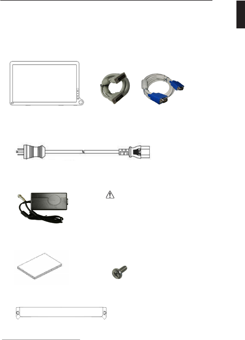
Symbol Denitions
AMM215MPWTD 7
ENGLISH
Dangerous: High Voltage
Direct Current
Serial Number
This way up
Fragile, handle with care
Stacking limit by number
Keep dry
Recyclable
See accompanying document
Indicates proof of confor-
mity to applicable European
EconomicCommunity Council
directives and to harmonized
standards published in the of-
cial journal of the European
Communities.
Authorized Representative in
Europe
Date of Manufacture
51LJ
Medical Equipment
E215822
Indicates protective earth
ground.
For indoor use only.
Tested to comply with FCC
Class B standards.
DC power control switch
Tested to comply with Japan
VCCI certication
Tested to comply with China
CCC certication
China RoHS symbol. Number
indicates EFUP(Environmental
Friendly Use Period) from the
date of manufacturing.
Medical Equipment is in ac-
cordance with UL 60601-1 and
CAN/CSA C22.2 No. 601.1
in regards to electric shock,
re hazards, and mechanical
hazards
Tested to comply with IP
(ingression protection) Rating
WEEE symbol for the
recyclable product. Please do
not throw the product with this
symbol in the bin.
Manufacturer

EU Declaration of Conformity for Medical Applications
A Declaration of Conformity has been led for this product. A sample
of this document may be found in the addendum which accompanied
this manual. For a copy of the Declaration of Conformity document,
please contact ADVAN Int’l Corp. and request for AMM215MPWTD
DOC.
Prepare for Unpack
Before you unpack your monitor, prepare a suitable workspace. You
need a stable and level surface near a grounded wall outlet in an area
which is relatively free of glare from sunlight or other sources of bright
light. The monitor is cooled by natural convection (it has no fan).
For optimum performance, do not block the cooling vents.
While unpacking the monitor, inspect it and other package contents
for shipping damage that could cause a re or shock hazard. Imme-
diately report any shipping damage to the carrier or transportation
company and contact customer service for monitor in the future or in
case of return.
After you unpack the monitor, make sure the following items are in-
cluded
• Monitor with video cable
• AC adapter with cable
CAUTION: AC Adapter must be plugged into Grounded a power outlet
CAUTION : AC adapter
Model No: JMW1100KB1300F02
• This operations manual
Note: Your system provider may offer alternative cords or cables
depending on the installation requirement and local geography issues.
8 User’s Guide

SAFETY PRECAUTION
· Avoid placing the monitor, or any other heavy object, on the power cord
to prevent re or electrical shock from damage to the power cord.
· Do not expose the monitor to rain, excessive moisture, or dust to avoid
re or shock hazard.
· Do not cover the slots or openings of the monitor for proper heat
dissipation. Always put the monitor in a place where there is adequate
ventilation.
· Avoid placing the monitor against a bright background or where sunlight
or other light sources may reect on the area of the monitor. Place the
monitor just below eye level.
· Handle with care when transporting the monitor.
· Refrain from giving the shock or scratch to the screen, as screen is
fragile.
CLEANING YOUR MONITOR
No specic liquid or chemical necessary when cleaning this LCD monitor
However, we suggest to clean the monitor with non-abrasive cloths and cleaning
solutions used in hospitals to clean similar equipment. We recommend using 70%
Isopropyl alcohol for the screen surface and warm water and a mild detergent for all
other surfaces. Other acceptable cleaning agents are listed below:
• 70% isopropyl alcohol
• Cidex (2.4% glutaraldehyde solution)
• 0.5% Chlorhexidine in 70% isopropyl alcohol
To clean the screen, do not spray liquid cleaners directly on to the unit. Stand away
Form the monitor and spray cleaning solution onto a cloth. Without applying exces-
sive pressure, clean the screen with the slightly dampened rag.
Recommendation to Use more than One Unit
As unforeseen situation can occasionally occur for the monitor, when the display
is used for safety control of human, equipments or unstable picture, or for
emergencies, we strongly recommend you use more than one unit or prepare a
spare unit.
AMM215MPWTD 9
ENGLISH
On Burn-in
Permanent burn-in may occur from the followings:
• Displaying color bar or static images repeately or for a long period of time.
• Using the unit repeatedly in a high temperature/ high humidity environment
• Displaying an image smaller than the monitor continuously.
To reduce the risk of burn- in, we recommend turning off the power of the unit, and
reducing the brightness when the unit is not in use.

POWER MANAGEMENT FUNCTION
The monitor is equipped with the power management function which automatically
reduce the power consumption when not in use in three power level modes.
• Stand-by Mode
The monitor goes into stand-by mode when the horizontal sync signal is off for
about 10 seconds. In this mode, the screen goes off and the power LED blinks
for 1 seconds On and 1 second Off. The screen is displayed after the horizontal
sync signal is restored.
• Suspend Mode
The monitor goes into suspend mode when the vertical sync signal is off for
about 10 seconds. In this mode, the screen goes off and the power LED blinks
for 1 seconds On and 1 second Off. The screen is displayed after the vertical
sync signal is restored.
• Off Mode
The monitor goes into power-off mode when the vertical and horizontal sync
signals are off for about 10 seconds. In this mode, the screen goes off and the
power LED blinks for 1 seconds On and 1 second Off. The screen is displayed
after the vertical and horizontal sync signals are restored.
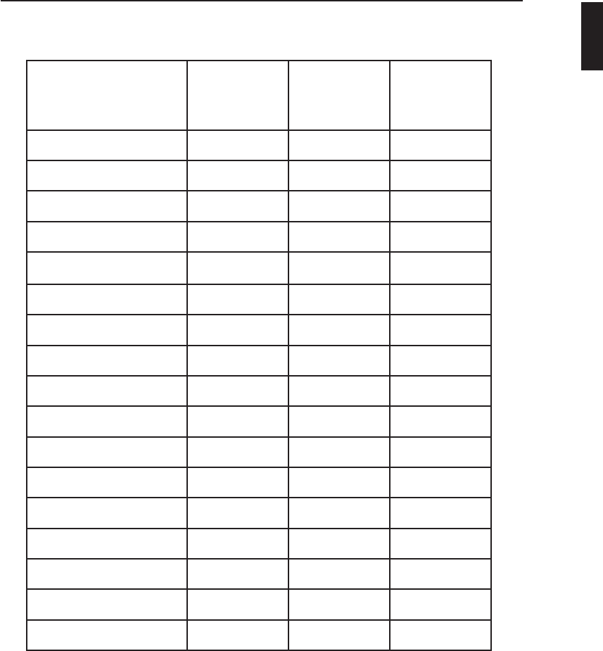
Power Management System
The AMM215MPWTD Medical Monitor power management proposal. Provides four
phases of power-saving modes by detecting the horizontal sync signal as shown in
the table below.
When the monitor is power saving mode or detects an incorrect timing, the screen
will be blank and power LED indicator will blink.
10 User’s Guide
PCoIP ON PCoIP OFF
State Normal
Operation
DPMS
Standby
DPMS
Suspend DPMS Off Normal
Operation
Normal
Operation
DPMS
Suspend DPMS Off
Horizontal
Sync Active Active Active Inactive Active Active Active Inactive
Vertical Sync Active Active Inactive Inactive Active Active Inactive Inactive
Video Active Blanked Blanked Blanked Active Blanked Blanked Blanked
Power
Indicator Green
Green
Flashing
(1 sec.
Interval)
Green
Flashing
(1 sec.
Interval)
Green
Flashing
(1 sec.
Interval)
Green
Green
Flashing
(1 sec.
Interval)
Green
Flashing
(1 sec.
Interval)
Green
Flashing
(1 sec.
Interval)
Power
Consumption 65 W 25 W 25 W 25 W 45 W 4.5 W 4.5 W 4.5 W
PRESET MODES
AMM215MPWTD 11
Resolution
Horizontal
frequency
( KHz )
Vertical
frequency
( Hz )
Pixel clock
( MHz )
640 x 350 @70Hz 31.469 70.087 25.175
640 x 480 @60Hz 31.469 59.940 25.175
640 x 480 @75Hz 37.500 75.000 31.500
800 x 600 @56Hz 35.156 56.250 36.000
800 x 600 @60Hz 37.879 60.317 40.000
800 x 600 @75Hz 46.875 75.000 49.500
1024 x 768 @60Hz 48.363 60.004 65.000
1024 x 768 @70Hz 56.476 70.069 75.000
1024 x 768 @75Hz 60.023 75.029 78.750
1152 x 864 @60Hz 54.348 60.053 80.000
1152 x 864 @70Hz 63.955 70.016 94.200
1152 x 864 @75Hz 67.500 75.000 108.000
1280 x 1024 @60Hz 63.981 60.020 108.000
1680 x 1050 @60Hz 64.742 59.946 119.125
1680 x 1050 @60Hz 65.160 59.944 147.000
1600 x 1200 @60Hz 74.077 59.981 130.375
1920 x 1080@60Hz 67.500 60.00 148.500
DVI and VGA input signal formats
ENGLISH
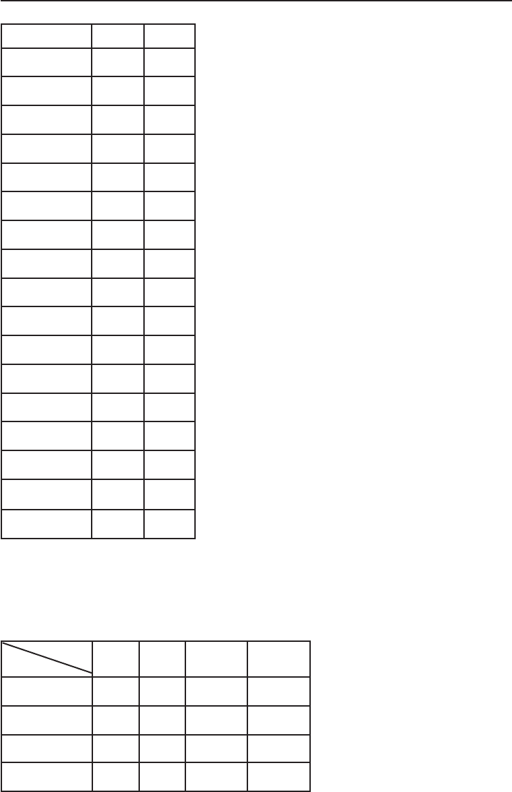
Video Signals
12 User’s Guide
Format DVI 1/2 VGA
480/59.94i O
480/59.94p
576/50i O
576/50p O O
720/50p O O
720/59.94p O O
720/60p O O
1080/23.98p O
1080/24p O
1080/25p O O
1080/29.97p O O
1080/30p O O
1080/50i O O
1080/59.94i O O
1080/60i O O
1080/50p O O
1080/60P O O
PIP / POP / PBP function
The following combination options are available to you:
PIP
Main DVI 1 DVI 2 PCoIP VGA
DVI 1 x x x O
DVI 2 x x x O
PCoIP x x x O
VGA O O O x
AMM215MPWTD 13
ENGLISH
DDC
To make your installation easier, the monitor is able to Plug and Play with your
system if your system also supports DDC protocol. The DDC (Display Data
Channel) is a communication protocol through which the monitor automatically
informs the host system about its capabilities, for example, supported resolutions
and corresponding timing. The monitor supports DDC1 and DDC2B standard.
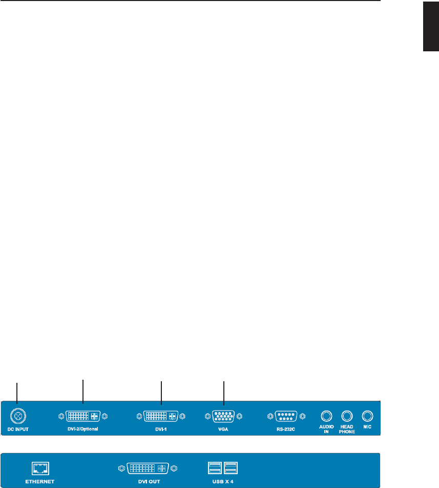
MONITOR INSTALLATION
To install the monitor to your host system, please follow the steps as given below:
Steps
1. Use the supplied cable (DVI, VGA) then connect to the
host system accordingly.
2. Connect the DC power to the DC power connector on the monitor.
3. Connect one end of AC power cord into the AC Adapter and the other end to AC
power outlet.
4. Then turn the host system on and then the monitor.
5. If the monitor still does not function properly, please refer to the troubleshooting
section to diagnose the problem.
DVI VGA
DC Power DVI
14 User’s Guide
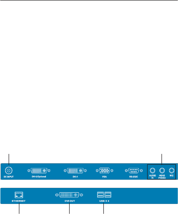
PCoIP INSTALLATION
To install the Zero client, please follow the steps as given below:
Steps
1. Use an Ethernet cable to connect the Ethernet switch or router to the Client’s
Ethernet jack.
2. Connect a USB keyboard and mouse to the USB ports.
3. If you are using dual monitors, use a DVI cable to connect DVI out to another
monitor.
4. Optionally connect the following to the Zero Client.
a. Audio in
b. Headphones
c. MIC
5. Connect the DC power to the DC power connector on the monitor.
6. Connect one end of AC power cord into the AC adapter and the other end to AC
power outlet.
7. Power on the monitor.
8. If the monitor still does not function properly, please refer to the troubleshooting
section to diagnose the problem.
Ethernet DVI Out USB
AudioDC Input
For more information on OSD, visit our website (http://www.advancorp.com)
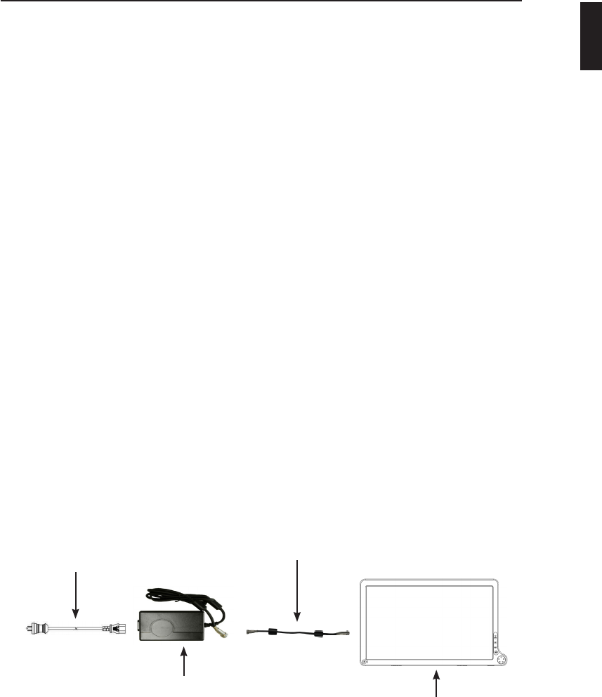
CONNECTING the POWER CORD
* Check rst to make sure that the power cord you use is the correct type required
for your area.
* This monitor has an universal AC adapter that allows operation in either
AC 100 - 240 V ac voltage area. No user-adjustment is required.
* Plug one end of the power cord to the AC adapter, plug another end to a proper
AC outlet.
The cord set should have the appropriate safety approvals for the country in which
the equipment will be installed and marked HAR.
For 120 volt Applications, use only UL Listed detachable power cord with NEMA
conguration 5-15P type (parallel blades) plug cap. For 240 volt applications use
only UL Listed Detachable power supply cord with NEMA conguration 6-15P type
(tandem blades) plug cap.
AMM215MPWTD 15
Hospital-grade
power cord
Power Supply
Model No: JMW1100KB1300F02 AMM215MPWTD
Extension power cord (optional)
Manufacturer: Bridgepower
Part No: CB-47D2001P50MF (5ft) or
CB-47D2004P57MF (15ft) or
CB-47D2022P86MF (75ft)
ENGLISH
16 User’s Guide
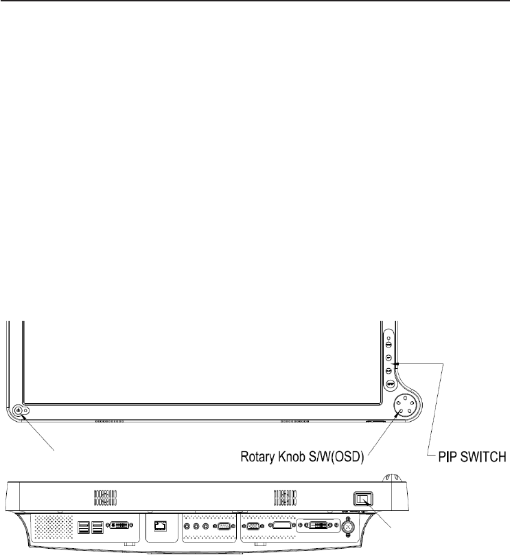
User Functions / Messages
Key Name and Function
Power LED: Lights up to indicate the power is turned ON.
Standby Power Button: To power ON or OFF the monitor.
Rotary switch (Turn right or left): With the OSD menu activated, increases or
decrease the value of the selected parameter. With the OSD deactivated, activates
the video source selection menu.
PCoIP button (Push): Turn ON client mode (Green LED ON) or to disconnect with
server (Green LED Blinking).
PCoIP button (Push and Hold): Turn OFF client mode (LED OFF)
PIP Switch (Push): To Enter PIP function or change to POP/PBP Mode.
PIP Switch (Push and Hold): Exit the PIP/POP/PBP Mode.
Adjust Switch*: To activate or deactivate image adjustment in sub screen of PIP,
PBP,POP mode.
Input Switch: To change the video source.
Power Switch: To turn ON or OFF the system.
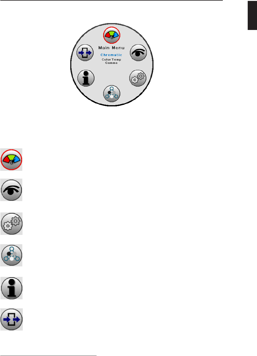
How to access the menu.
1. Push the “Knob” button to activate the OSD menu.
2. Able to turn left or right the button to select those icons. The icon will be
highlighted when is selected.
3. Push the “knob” button to go into the another OSD menu.
4. Turn left or right “Knob” button to increase or decrease the number of selected
function.
5. In order to exit from the OSD menu in a different layer, then choose the “Exit
option”. In case of long pushing and holding the button around two or three
seconds, then it will completely out from the menu regardless wherever you are.
6. Turn the “Knob” button in a fast way to the left or right, while the menu is not
activated, then input signal menu will turns up with “V” mark which is chosen
current available input signal. You can switch to another input signal source by
turning the knob slowly then select the target source by pushing the knob.
Standby Power Button
Power Switch
AMM215MPWTD 17
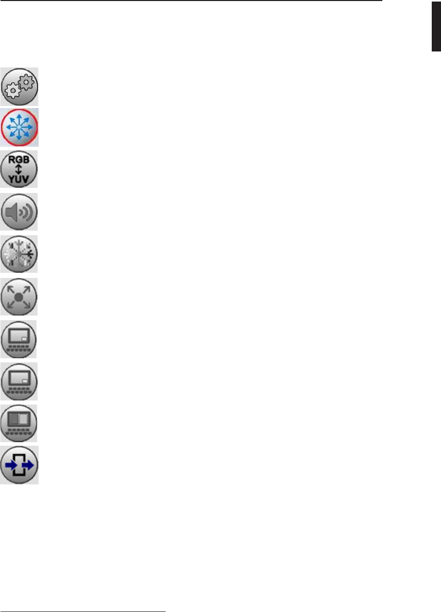
OSD Section
Chromatic Adjust Color Temp, Gamma
Visual Adjust Brightness, Contrast, Phase*, Chroma*,
Sharpness-H, Sharpness-V
Setting Adjust Scale Mode, Color Space*, Speaker, Freeze Frame,
Zoom / Pan, PIP, POP, PBP
Advanced Adjust OSD Position Control, Screen Control, DPMS, Auto
Source Select, Smart Select, Restore Factory, Key Lock,
Overscan
Information Adjust Custom Entry, SN, Run Time, Input Format
Exit Exit the menu
Main Menu
ENGLISH
*Functions not available for AMM215MPWTD
18 User’s Guide
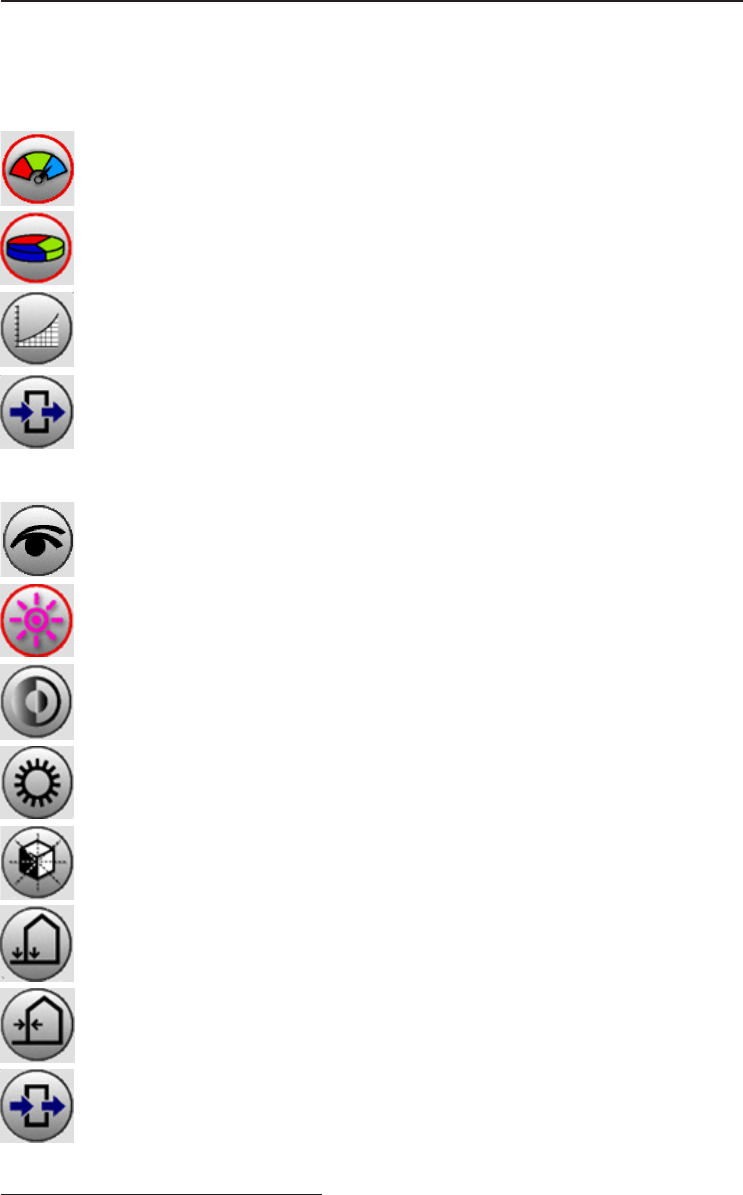
OSD Section
Chromatic
Color Temp Change the color temperature - D65, D93, S1, S2
Gamma Change the gamma value - 1.8, 1.9, 1.95, 2.1, 2.1S, 2.2, 2.3,
2.4, 2.4S, S0, Radio graph
Exit Exit the menu
Visual
Brightness Adjust the brightness of panel (Range 0 - 100)
Contrast Adjust the contrast of video (Range 0 - 100)
Phase* Adjust the phase of video (Range 0 - 100)
Chroma* Adjust the chroma of video (Range 0 - 100)
Sharpness-V Set the sharpness of vertical image (Range 0 - 20)
Sharpness-H Set the sharpness of horizontal image (Range 0 - 20)
Exit Exit the menu
*Functions not available for AMM215MPWTD
OSD Section
Setting
Scale Mode Change the scale mode - Fill all, One to One,
Vertical - ll, Horizontal - ll, Fill aspect ratio
Color Space* Change color space between RGB and YPbPr
Speaker Adjust volume (Range 0 - 100)
Freeze Frame Off / On freeze frame
Zoom / Pan Enable zoom - in and pan function
PIP Enable PIP (Picture In Picture) function
POP Enable POP (Picture On Picture) function
PBP Enable PBP (Picture By Picture) function
Exit Exit the menu
AMM215MPWTD 19
ENGLISH
*Functions not available for AMM215MPWTD
20 User’s Guide
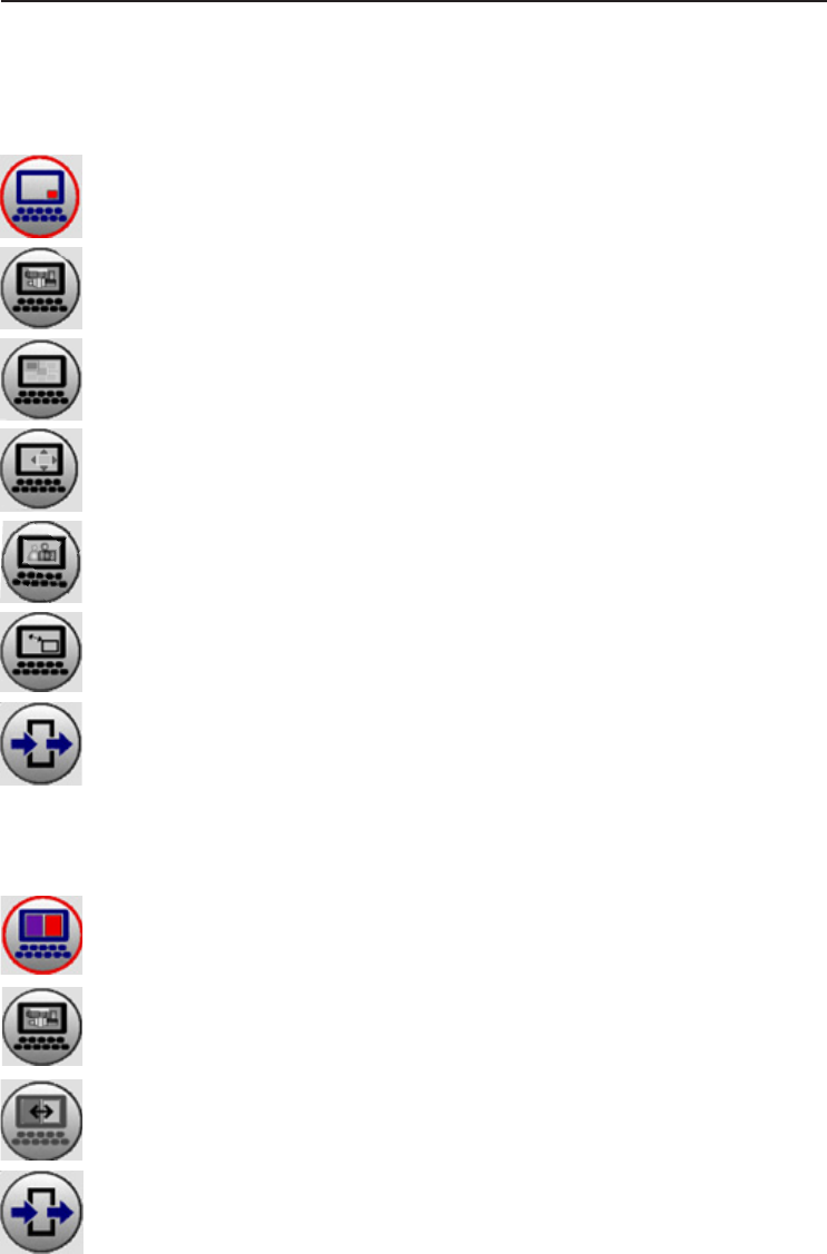
OSD Section
Mode PIP Mode ON / Off
Source PIP sub screen source - VGA, DVI1/2, PCoIP
Position PIP sub screen position - Top L, Top R, Bottom L, Bottom R
Size PIP sub screen size - Small, Medium, Large
Blending PIP sub screen blending (Range 0 - 20)
Swap PIP sub screen swap
Exit Exit the menu
Mode PBP Mode ON / Off
Source PBP sub screen source - VGA, DVI1/2, PCoIP
Swap PBP sub screen swap
Exit Exit the menu
Sub menu of PBP
Sub menu of PIP

Mode POP Mode ON / Off
Source POP sub screen source - VGA, DVI1/2, PCoIP
Position POP sub screen position - Top L, Top R, Bottom L, Bottom R
Size POP sub screen size - Small, Medium, Large
Blending POP sub screen blending (Range 0 - 20)
Swap POP sub screen swap
Exit Exit the menu
Sub menu of POP
AMM215MPWTD 21
OSD Section
ENGLISH
22 User’s Guide
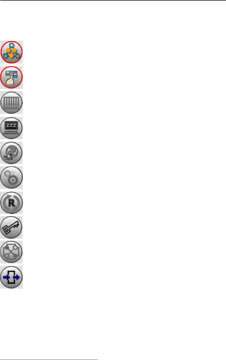
OSD Section
Advanced
OSD Position Change the OSD menu - Position, Background,
Control OSD time out, Language
Screen Control Control and adjust H and V position, Freqency, Phase
Noise Reduction*, Motion Offset*
DPMS Change the DPMS
Auto Source Adjust Auto Source Select between on and off
Select
Smart Select Enable / Disable smart select sub menu
Restore Factory Changes the all OSD value to factory outgoing status
Key Lock Set to key lock mode
Overscan Adjust Overscan ratio
Exit Exit the menu
*Functions not available for AMM215MPWTD
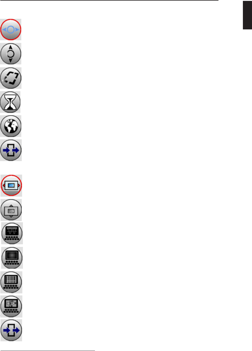
OSD Section
Sub menu of OSD Control
H-position Adjust OSD H - position (Range 0 - 100)
V-position Adjust OSD V - position (Range 0 - 100)
Back ground Adjust transparency of OSD back ground (Range 0 - 20)
OSD Time out Adjust OSD time out - 5s, 10s, 15s, 20s, 1m, 2m
Language OSD language - English, Japanese, Chinese, Korean,
French, German
Exit Exit the menu
H-position Adjust screen H - position (Range 0 - 100)
*available for VGA
V-position Adjust screen V - position (Range 0 - 100)
*available for VGA
Frequency Adjust frequency (Range 0 - 100)
*available for VGA
Phase Adjust phase (Range 0 - 100)
*available for VGA
Noise Noise reduction (Range 0 - 31)
Reduction*
Motion Offset* Motion offset (Range 0 - 100)
Exit Exit the menu
Sub menu of Screen Control
AMM215MPWTD 23
ENGLISH
*Functions not available for AMM215MPWTD

24 User’s Guide
OSD Section
Information
Custom Entry Change the user or monitor’s name
SN Display the serial number
Run Time Display the total run time
Input Format Display the current input resolution and vertical frequency
Exit Exit the menu

TROUBLESHOOTING
Before sending your LCD monitor for servicing, please check the troubleshooting
list below to see if you can self-diagnose the problem.
AMM215MPWTD 25
Problems Current Status Remedy
No Picture LED ON · Using OSD, adjust brightness and
contrast to maximum or reset to their
default settings.
LED OFF · Check the Rocker switch and Power
switch.
· Check if AC power cord is properly
connected to the AC adapter.
LED Blinking · Check if video signal cable is properly
connected at the back of monitor.
· Check if the power to computer system
is ON.
Abnormal Picture Unstable Picture · Check if the specication of graphics
adapter and monitor is in compliance
which may be causing the input signal
frequency mismatch.
Display is missing, center shift,
or too small or too large in
display size
· Using the Screen Control Menu, adjust
the Phase, Frequency, Horizontal, and
Vertical settings in order to correct the
display image.
ENGLISH

26 User’s Guide
SPECIFICATION*
* All contents are subject to change without notice.
Model AMM215MPWTD
Client
Processor TERA2321 PCoIP Client Processor
Memory 512MB DDR3
LCD Panel
Description a-Si TFT Active Matrix, LED Backlight
Active Screen Size 21.46 inches (545.22mm) diagonal
Resolution 1920 (H) x 1080 (V) @60Hz
Pixel Pitch 0.2475 mm
Display Color 16.7M colors
Color Tone Up to 256 color tone
Response Time <25ms (Typ.)
Face Finishing Protective Filter with Anti-Reected Hard Coated
Viewing Angle R/L 178°, U/D 178° (CR > 10)
Brightness** 250 cd/m2 (Typ.)
Contrast Ratio 1000:1 (Typ.)
Input
VGA
15pin D-Sub x 1
R/G/B : 0.7 ± 0.1 Vp-p
H/V Sync : TTL Level (V high ≥2.3V, V low ≤0.5V)
DVI1 DVI-I x 1
DVI2 / Optional Input DVI-I x 1
Remote Input 9–pin D-Sub (RS-232C) x 1
Audio In Stereo Phone Jack
20~20,000hz Audio signal, Max 1 Vrms stereo signal
MIC In Stereo Phone Jack
20~20,000hz Audio signal
USB In A-type USB Receptacle. x 4
USB 2.0 Interface, support up to 500mA per USB port.
Ethernet RJ45 x 1
Scanning Frequency Horizontal : 31.47~80.0Khz Vertical : 50~85Hz
Output
DVI DVI-I x 1
Headphone Stereo Phone Jack
60mW at 32 ohm head phone load
Speaker Dynamic Speaker x 2
1.3W (Max)/8ohm
General
Power Adaptor AC 100 ~ 240V 50-60Hz, 2.0A
DC 13V, 6.92A
Power Consumption 60W
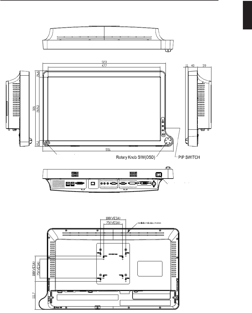
Dimension 523 (W) x 321 (H) x 110 (D) mm
Weight Monitor: 5.42Kg (Approximately)
AC adaptor: 720g
VESA Mounting 100mm x 100mm
Operating/Storage Environment
Operating Temperature 32° ~ 95°F (0° - 35°C)
Operating Humidity 20% ~ 80%, non-condensing
Storage Temperature -4° ~ 140°F (-20° - 60°C)
Storage Humidity 10 ~ 85%RH (without condensation)
Compliance &Certication
Safety UL (UL60601-1), cUL (CAN/CSA-C22.2 No.6011-M90), CE (EN60601-1), AS/NZS 3200-1-0.
CCC (GB4943-2001), CB-ITE (IEC60950-1), IP23 Compliance
EMC FCC (Part 15 Class B), CE (EN60601-1-2), AS/NZS 3200-1-2, VCCI (Class B), CCC
(GB9254, GB17625.1)
Optional Module
DC Extension Cable 5ft, 15ft, 75ft length
Base Stand Adjustable high, swivel and tilt base stand
This monitor is intended for use in Health Care Facilities model AMM215MPWTD
Equipment is not suitable for use in the presence of ammable anesthetic mixture
with air or with oxygen or nitrous oxide.
No user serviceable parts inside, ask qualied personnel when accessing inside.
For disposal of waste product, follow the requirement of local code.
Electrical input rating: 13V DC 6.92A
Classication
Type of protection against electric shock: Class I Equipment.
Degree of protection against the ingress of water: IP23 compliance.
Mode of operation: Continuous
This monitor has been tested to comply with IEC/EN 60601-1, IEC/EN60601-1-2
and is certied by UL to medical standard UL60601-1(UL/cUL Mark).
Because many medical ofces are located in residential areas, this monitor, in ad-
dition to the medical requirements, has also been tested and found to comply with
the limits for FCC Class B computing devices in a typically congured system. It is
the system integrator or congurer’s responsibility to test and ensure that the entire
system complies with applicable EMC laws.
Environmental conditions for transport and storage:
- Temperature range within -4° to 140° F (-20° to 60°C)
- Relative humidity range within 10% to 85%
- Atmospheric pressure range within 500 to 1060 hPa.
: UL approval mark according to the
safety standard for Medical equipment
: Direct Current
MEDICAL EQUIPMENT
WITH RESPECT TO ELECTRIC SHOCK,
FIRE AND MECHANICAL HAZARDS ONLY
IN ACCORDANCE WITH UL 60601-1, AND
CAN/CSA C22.2 NO. 601.1
51LJ
Medical Equipment
E215822
AMM215MPWTD 27
ENGLISH
28 User’s Guide
Electromagnetic Compatibility
Like other electrical medical equipment, the AMM215MPWTD requires special
precautions to ensure electromagnetic compatibility with other electrical medical devices.
To ensure electromagnetic compatibility (EMC), the AMM215MPWTD must be installed and
operated according to the EMC information provided in this manual.
Note The AMM215MPWTD has been designed and tested to comply with IEC
60601-1-2:2001 requirements for EMC with other devices.
Caution Portable and mobile RF communications equipment may affect
the normal function of the AMM215MPWTD.
Warning Do not use cables or accessories other than those provided
with the AMM215MPWTD, as this may result in increased electromagnetic
emissions or decreased immunity to such emissions.
Warning If the AMM215MPWTD is used adjacent to or stacked with
other equipment, observe and verify normal operation of the AMM215MPWTD
in the conguration in which it will be used prior to using it in
a
surgical pro-
cedure. Consult the tables below for guidance in placing the AMM215MPWTD.
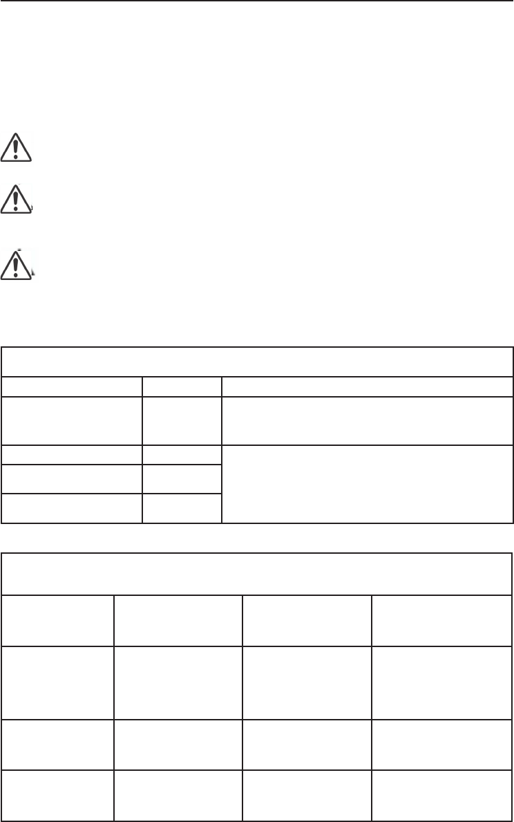
The Model AMM215MPWTD is intended for use in the electromagnetic environment specied below.
The customer or the user of AMM215MPWTD should assure that it is used in such an environment.
Emission test Compliance Electromagnetic environment - guidance
RF emissions CISPR 11 Group 1
The Model AMM215MPWTD uses RF energy only for its internal
function. Therefore, its RF emissions are very low and are not
likely to cause any interference in nearby electronic equipment
RF emissions CISPR 11 Class B
AMM215MPWTD is suitable for use in all establishments,
including domestic establishments and those directly connected
to the public low-voltage power supply network that supplies
buildings used for domestic purposes
Harmonic emissions
IEC61000-3-2 Class D
Voltage Fluctuations
IEC61000-3-3 Complies
Manufacturer’s declaration - electromagnetic emission
The Model AMM215MPWTD is intended for use in the electromagnetic environment specied below.
The customer or the user of AMM215MPWTD should assure that it is used in such an environment.
Immunity Test IEC 60601 Test Level Compliance Level Electromagnetic
environment - guidance
Electrostatic discharge
(ESD)
IEC61000-4-2
6 kV contact
8 kV air
6 kV contact
8 kV air
Floors should be wood,
concrete or ceramic tile.
If oors are covered with
synthetic material, the relative
humidity should be at least
30%.
Electrical fast transient
/burst IEC61000-4-4
2 kV for power supply lines
1 kV for input / output lines
2 kV for power supply lines
1 kV for input / output lines
Mains power quality
should be that of a typical
commercial or hospital
environment.
Surge
IEC61000-4-5
1 kV differential mode
2 kV common mode
1 kV differential mode
2 kV common mode
Mains power quality
should be that of a typical
commercial or hospital
environment.
Manufacturer’s declaration - electromagnetic immunity
Power frequency
(50/60Hz) mag-
netic eld
IEC 61000-4-8
3.0 A/m 3.0 A/m
Power frequency mag-
netic elds should be
at levels characteristic
of a typical location in
a typical commercial or
hospital environment.
Voltage dips, short
interruptions and
voltage variations on
power supply input
lines IEC61000-4-11
<5% Ut (>95% dip in Ut)
for 0.5 cycle
40% Ut (60% dip in Ut)
for 5 cycles
70% Ut (30% dip in Ut)
for 25 cycles
<5% Ut (>95% dip in Ut)
for 5 sec.
<5% Ut (>95% dip in Ut)
for 0.5 cycle
40% Ut (60% dip in Ut)
for 5 cycles
70% Ut (30% dip in Ut)
for 25 cycles
<5% Ut (>95% dip in Ut)
for 5 sec.
Mains power quaility
should be that of a typical
commercial or hospital
environment. If the user
of the AMM215MPWTD
image intensier requires
continued operation dur-
ing power mains interrup-
tions, it is recommended
that the AMM215MPWTD
image intensier be
powered from an uninter-
ruptible power supply or
a battery.
Note: Ut is the A.C. mains voltage prior to application of the test level.
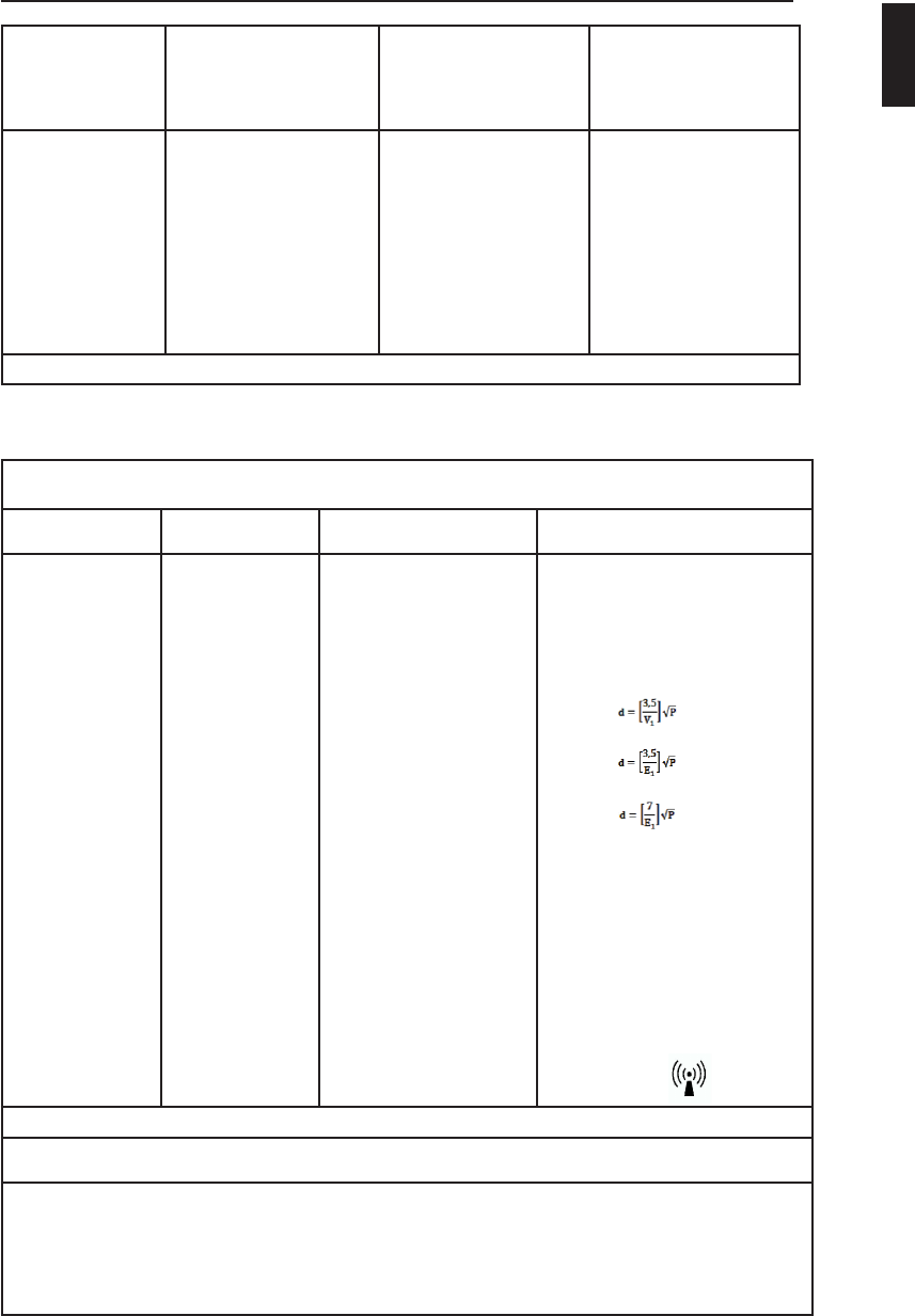
The Model AMM215MPWTD is intended for use in the electromagnetic environment specied below.
The customer or the user of AMM215MPWTD should ensure that it is used in such an environment.
Immunity Test IEC 60601 Test
Level Compliance Level Electromagnetic environment
- guidance
Conducted RF
IEC61000-4-6
Radiated RF
IEC 61000-4-3
3 Vrms
150 KHz to 80 MHz
3 V/m
80MHz to 2.5 GHz
3 Vrms
150 KHz to 80 MHz
3 V/m
80MHz to 2.5 GHz
Portable and mobile RF communications
equipment should be used no closer
to any part of the AMM215MPWTD,
including cables, than the recommended
separation distance calculated from the
equation applicable to the frequency of the
transmitter.
Recommended Separation Distance
0.15 MHz to 80 MHz
80 MHz to 800 MHz
800 MHz to 2.5 GHz
where P is the maximum oputput power
rating of the transmitter in watts (W)
according to the transmitter manufacturer
and d is the recommended separation
distance in meters (m).
Field strengths from xed RF transmitters,
as deter-mined by an electromagnetic
site survey (a), should be less than the
compliance level in each frequency range
(b).Interferency may occur in the vicinity
of equipment marked with the follwing
symbol:
NOTE 1: At 80MHz and 800MHz, the higher frequency range applies.
NOTE 2: These guidelines may not apply in all situations. Electromagnetic propagation is affected by absorption and
reection from structures, objects, and people.
(a) Field strengths from xed transmitters, such as base stations for radio (cellular/cordless) telephones and land mobile
radios, amateur radio, AM and FM radio broadcast and TV broadcast, connot be predicted theoretically with accuracy.
To assess the electromagnetic environment due to xed RF transmitters, an electromagnetic site survey should be con-
sidered. If the measured eld strength in the location in which the AMM215MPWTD is used exceeds the applicable RF
compliance level above, the AMM215MPWTD should be observed to verify normal operation. If abnormal performance
is observed, additional measures may be necessary, such as reorienting or relocating the AMM215MPWTD.
(b) Over the frequency range 150kHz to 80MHz, eld strengths should be less than [V1] V/m.
Manufacturer’s declaration - electromagnetic immunity
AMM215MPWTD 29
ENGLISH
30 User’s Guide
Recommended Separation Distances Between Portable and Mobile RF Communications Equi-
pement and the AMM215MPWTD System
The AMM215MPWTD system is intended for use in an electromagnetic environment in which radiated RF
disturbances are controlled. The user of the AMM215MPWTD system can help prevent electromagnetic
interference by maintaining a minimum distance between portable and mobile RF communications
equipment (transmitters) and the AMM215MPWTD system as recommended below, according to the
maximum output power of the communications equipment.
Rated maximum output
power (W) of transmitter
Separation distance (m) according to frequency of transmitter
150kHz to 80MHz
d=1.17, p
80MHz to 800MHz
d=1.17, p
800MHz to 2.5GHz
d=2.33, p
0.01 0.12 0.12 0.23
0.1 0.37 0.37 0.74
1 1.17 1.17 2.33
10 3.70 3.70 7.37
100 11.70 11.70 23.30
For transmitters rated at a maximum output power not listed above, the recommended separation distance (d) in me-
ters (m) can be estimated using the equation applicable to the frequency of the transmitter, where P is the maximum
output power rating of the transmitter in watts (W) according to the transmitter manufacturer.
NOTE 1: At 80 MHz and 800 MHz, the separation distance for the higher frequency range applies.
NOTE 2: These guidelines may not apply in all situations. Electromagnetic propagation is affected by absorption and
reection from structures, objects, and people.
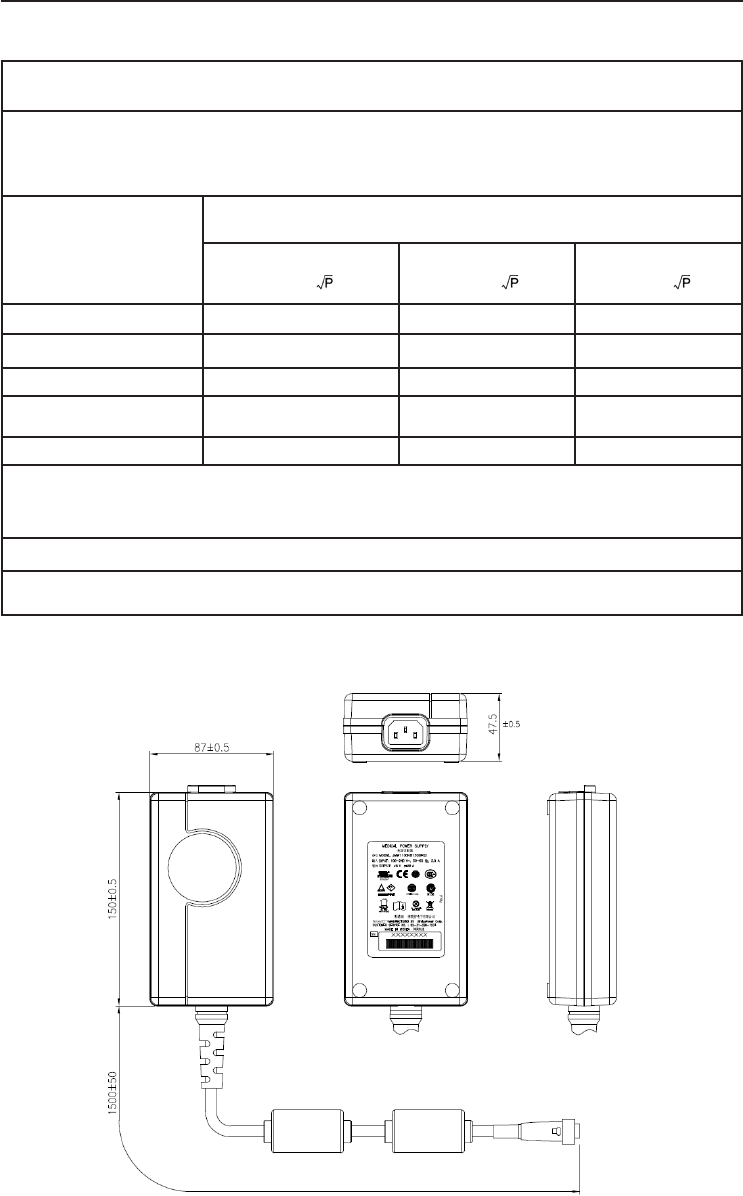
Dimension Drawing (mm) of AC Adapter
AMM215MPWTD 31
ENGLISH
Dimension Drawing (mm) of AMM215MPWTD
Power Switch
Standby Power Button
32 User’s Guide
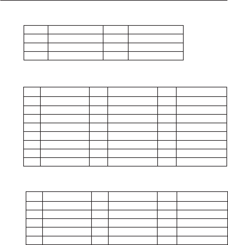
Connectors
DC Input
Connector Jack Power Input
Video Input
24 pin DVI-I connector.
DDWG or equivalent connector.
Pin Description Pin Description Pin Description
1 T.M.D.S. Data2- 9T.M.D.S. Data1- 17 T.M.D.S. Data0-
2 T.M.D.S. Data2+ 10
T.M.D.S. Data1+
18 T.M.D.S. Data0+
3T.M.D.S. Data2 Shield 11 T.M.D.S. Data1 Shield 19 T.M.D.S. Data0 Shield
4 NC 12 NC 20
NC
5NC 13 NC 21 NC
6DDC Clock 14 +5V Power 22 T.M.D.S. Clock Shield
7 DDC Data 15 Ground (for +5V 23 T.M.D.S. Clock+
8 NC 16 Hot Plug Detect 24 T.M.D.S. Clock-
15 pin VGA connector.
Pin Description Pin Description Pin Description
1RED 6GND- RED 11 GND
2GREEN 7 GND- GREEN 12 DDC SDA
3 BLUE 8 GND- BLUE 13 HSYNC
4 GND 9 G5V 14 VSYNC
5GND 10 GND 15 DDC SCL
Pin Description Pin Description
1GND 4 NC
2GND 5 13V Input
313 V Input

AMM215MPWTD 33
ENGLISH
Description of Warranty
ADVAN warrants to the rst Buyer (Buyer) that the product purchased when
shipped in its original container will conform to ADVAN specications, and to any
ADVAN approved specications furnished to ADVAN by the Buyer, and will be
free of defects in materials and workmanship. ADVAN warrants that the product
purchased is manufactured from new components which meet ADVAN standards,
quality and specications.
Subject to the conditions and limitations set forth below, ADVAN will, at its option,
either repair any component of its products that prove defective by reason of
improper workmanship or materials or ADVAN has the exclusive right to replace
with refurbished units or with an equivalent product. ADVAN warrants that the
components used for repair, refurbished units or equivalent product will meet
ADVAN standards, quality and specications.
Commencement and Duration of Warranty
The product purchased will be warranted for a period of eighteen (18) months
(excluding the LCD panel, touch screen, and the protection lter) from the date of
shipment.
LCD panels and touch screens are warranted for a period of twelve (12) months
from the date of shipment.
Protection lters are not warranted as damage to the protection lter is considered
to be normal wear and tear and can be replaced at Buyer’s cost.
Components used for repair, refurbished units or equivalent product will be
warranted for a period of twelve (12) months from the date of repair.
Limitation of Warranty
This limited warranty does not cover any damage to this product or other non-
ADVAN products that results from any of the following: improper installation
or operation; accident; abuse; misuse; natural disaster; war; insufcient or
excessive electrical supply; abnormal mechanical or environmental conditions; any
unauthorized disassembly, repair or modication; normal wear and tear; tampering
by anyone other than an ADVAN engineer or an ADVAN Authorized Service Center
(ASC); the use of supplies, consumable items and conditions beyond the control
of ADVAN, such as common carrier provided equipment and/or facilities; operation
of ADVAN product in excess of the specications. This limited warranty also does
not apply to any product that has not been handled or packaged correctly, that has
been sold as second-hand or has been resold contrary to the US export regulations,
on which the original identication information (i.e. serial number, rating and/or
warranty label) has been altered, obliterated or removed.

34 User’s Guide
Return Material Authorization (RMA) Procedure
All claims must be submitted through the ADVAN website, whether in warranty
or out, rst Buyer, distributor or OEM. End Users who have purchased through a
distributor or OEM, please contact the distributor or OEM.
http://www.advancorprma.com
Follow the instructions to receive an RMA number, shipping instructions and a
shipping label to be placed on the outside of the shipping container. A serial
number and a detailed reason for return are required.
In-transit damage is not covered by warranty. ADVAN will only pay for the return
shipment by surface transportation.
Returns without an RMA number will not be accepted.
For product support, please e-mail details of your inquiry including product model:
service@advancorp.com
In Warranty
ADVAN or its ASC will repair or replace if defective in material or workmanship
without cost, for a period of eighteen (18) months, (LCD panels and touch screens
for a period of twelve (12) months) after the date of shipment.
Buyer must notify ADVAN or its ASC of the defect before expiration of the warranty
period, and request an RMA number. If the conguration has been modied in
any manner, the product must be returned to its original conguration before any
warranty service will be performed by ADVAN or its ASC. No goods are to be
returned to ADVAN or its ASC without prior authorization. Buyer will be responsible
for packaging (preferably original container) and shipping the defective goods to
ADVAN or its ASC, shipping charges prepaid.
ADVAN or its ASC will return the in warranty product, at no cost to the buyer.

AMM215MPWTD 35
ENGLISH
Out-of-Warranty
ADVAN or its ASC will repair or replace if defective in material or workmanship with
fee, any product which the warranty period has expired (out-of-warranty).
Buyer must notify ADVAN or its ASC of the defect and request an RMA number. If
the conguration has been modied in any manner, the product must be returned to
its original conguration before any service will be performed by ADVAN or its ASC.
No goods are to be returned to ADVAN or its ASC without prior authorization. Buyer
will be responsible for packaging (preferably original container) and shipping the
defective goods to ADVAN or its ASC, shipping charges prepaid.
ADVAN or its ASC will return the out-of-warranty product, at cost to the buyer.
Product End of Life (EOL)
In the event of an RMA of an EOL product(s), ADVAN will hold or store major
components of its products for a period of ve (5) years, after the EOL of its
products. ADVAN shall continue to perform the service of its products as long as
ADVAN holds or stores said components of the products, with reasonable charge.
The forgoing Warranty and Out-of-Warranty terms apply.

36 User’s Guide
Disclaimer
THE FORGOING IS THE COMPLETE WARRANTY FOR ADVAN PRODUCTS
AND SUPERSEDES ALL OTHER WARRANTIES AND REPRESENTATIONS,
WHETHER ORAL OR WRITTEN. EXCEPT AS EXPRESSLY SET FORTH
ABOVE, NO OTHER WARRANTIES ARE MADE WITH RESPECT TO ADVAN
PRODUCTS AND ADVAN EXPRESSLY DISCLAIMS ALL WARRANTIES NOT
STATED HEREIN, INCLUDING, TO THE EXTENT PERMITTED BY APPLICABLE
LAW, ANY WARRANTY THAT MAY EXIST UNDER NATIONAL, STATE,
PROVINCIAL OR LOCAL LAW INCLUDING BUT NOT LIMITED TO ANY IMPLIED
WARRANTY ON NON-INFRINGEMENT, MERCHANTABILITY OR FITNESS
FOR A PARTICULAR PURPOSE. ALL WARRANTIES, WHETHER EXPRESS
OR IMPLIED, ARE LIMITED TO THE PERIODS OF TIME SET FORTH ABOVE.
SOME STATES OR OTHER JURISDICTIONS DO NOT ALLOW THE EXCLUSION
OF IMPLIED WARRANTIES OR LIMITATIONS ON HOW LONG AN IMPLIED
WARRANTY LASTS, SO THE ABOVE LIMITATIONS MAY NOT APPLY.
ADVAN’S TOTAL LIABILITY UNDER THIS OR ANY OTHER WARRANTY,
EXPRESSED OR IMPLIED, IS LIMITED TO REPAIR OR REPLACEMENT, AND
ARE THE SOLE AND EXCLUSIVE REMEDIES FOR BREACH OF WARRANTY
OR ANY OTHER LEGAL THEORY. TO THE FULLEST EXTENT PERMITTED
BY APPLICABLE LAW, ADVAN SHALL NOT BE LIABLE TO THE PURCHASER
OR END USER CUSTOMER OF AN ADVAN PRODUCT FOR ANY DAMAGES,
EXPENSES, LOST DATA, LOST REVENUES, LOST SAVINGS, LOST PROFITS,
OR ANY OTHER INCIDENTAL OR CONSEQUENTIAL DAMAGES ARISING
FROM THE PURCHASE, USE OR INABILITY TO USE THE ADVAN PRODUCT,
EVEN IF ADVAN HAS BEEN ADVISED OF THE POSSIBILITY OF SUCH
DAMAGES. SOME STATES OR OTHER JURISDICTIONS DO NOT ALLOW
THE EXCLUSION OR LIMITATION OF INCIDENTAL OR CONSEQUENTIAL
DAMAGES, SO THE ABOVE LIMITATIONS MAY NOT APPLY.
THE LIMITED WARRANTY GIVES YOU SPECIFIC LEGAL RIGHTS, AND YOU
MAY ALSO HAVE OTHER RIGHTS WHICH VARY FROM STATE TO STATE OR
JURISDICTION TO JURISDICTION.
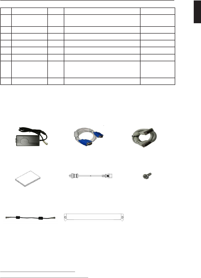
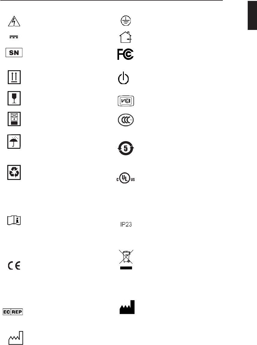
Accessory Item List
No. Parts Name Q’ty Description Remark
1AC- Adaptor 1 Model Number: JMW1100KB1300F02
Parts Number: PS-52141209002E
BridgePower
2VGA Cable 1 RGB 15P TO 15P, 1.8M, IVORY
3 DVI cable 1 DVI-I type CABLE 29P TO 29P
4 User’s Manual 1Rev. A
5Power Cord*1 Medical Grade 115V, GRAY
6VESA Screw 4 BH,+,M4x10,Ni
7 Extension Power
Cord** 1 Part No: CB-47D2001P50MF (5ft) or
CB-47D2004P57MF (15ft) or
CB-47D2022P86MF (75ft)
BridgePower
8 Cable Cover 1
* Might vary pending on region standard
**Optional item, check with local representative
Adaptor VGA Cable DVI Cable
User’s Manual Power Cord* VESA Screw
Extension
Power Cord ** Cable Cover
AMM215MPWTD 37
ENGLISH
ADVAN Korea
#605, Kolon Science Valley 2-cha, 55, Digital-ro, 34-gil, Guro-gu, Seoul, 152-728
Korea
Tel : +82 2 783 5197
Fax : +82 2 868 0880
Web Page : http://www.advancorp.com
ADVAN INT’L CORP
47817 Fremont Blvd. Fremont, CA 94538, USA
Tel : 1 510 490 1005
Fax : 1 510 490 1151
Web Page : http://www.advancorp.com