BARCO AMM215MWTD LCD Color Display (Model: AMM215MWTD) User Manual
Advan Int'l Corp. LCD Color Display (Model: AMM215MWTD)
UserManual.wiki
>
BARCO
>
AMM215MWTD User Manual
User Manual
Navigation menu
Upload a User Manual
Namespaces
Wiki Guide
HTML
PDF
Info
Views
User Manual
Discussion / Help
Navigation
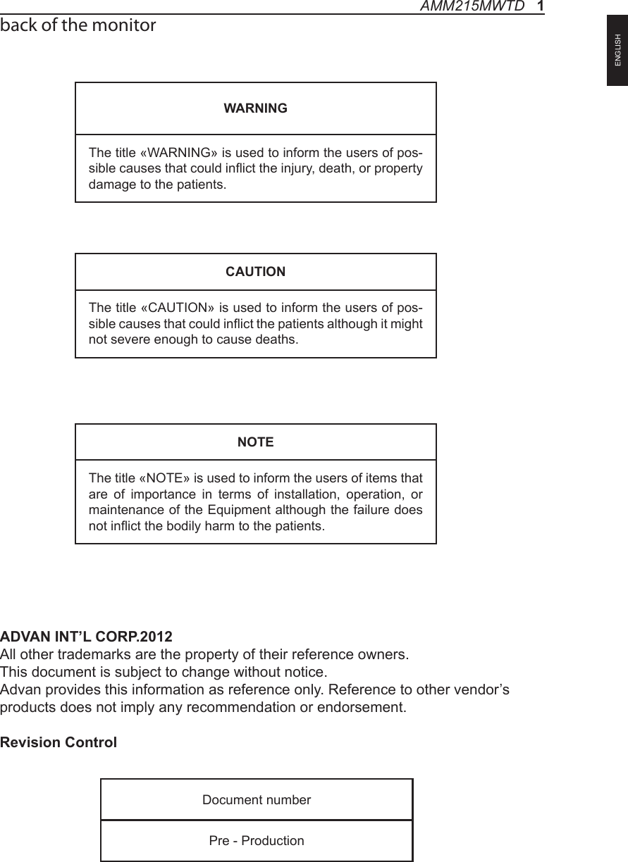
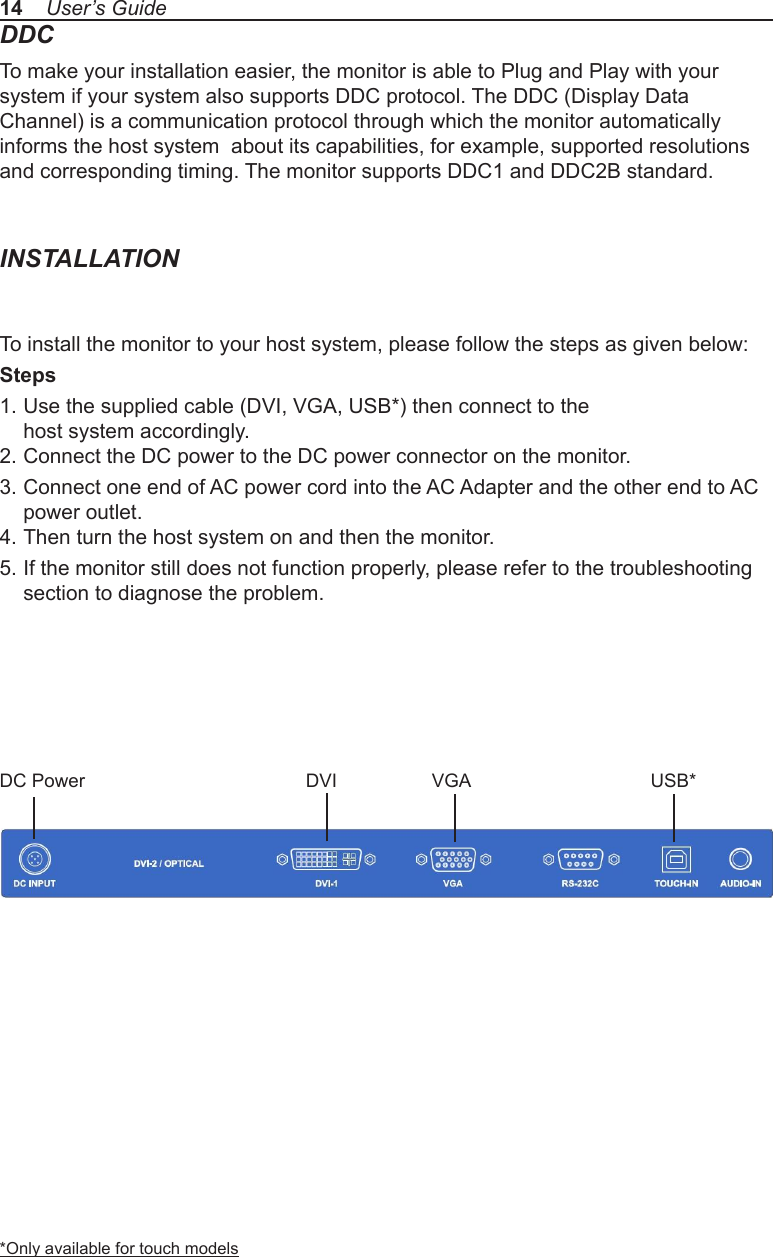
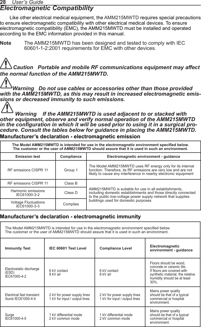
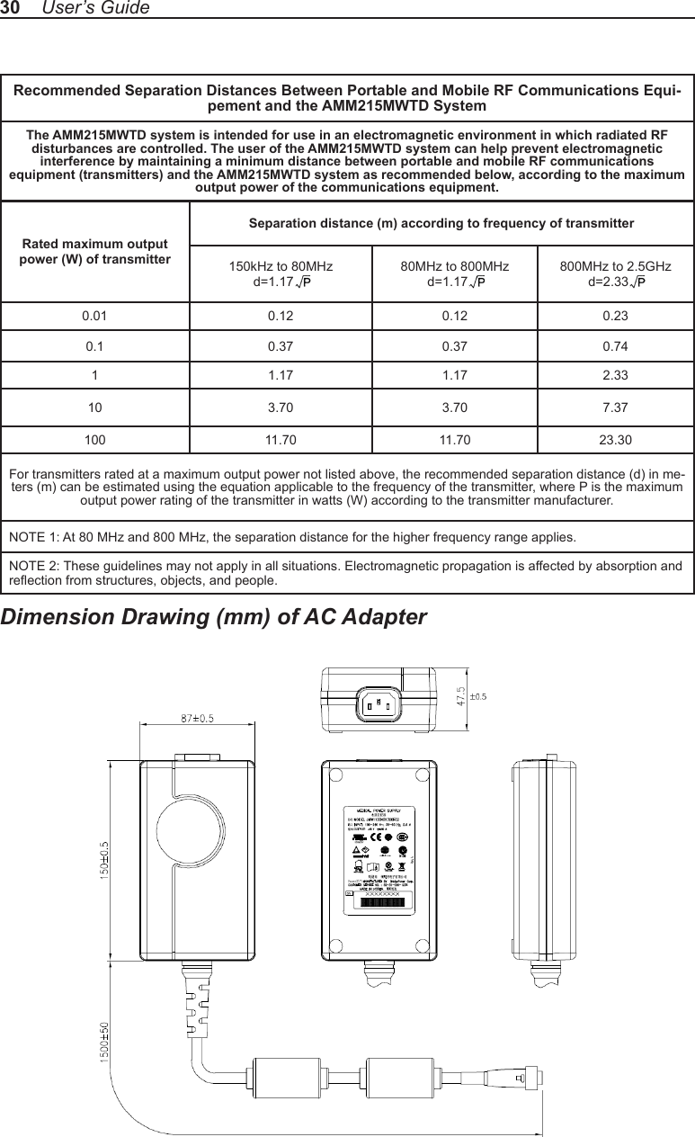
![Power frequency (50/60Hz) mag-netic eld IEC 61000-4-8 3.0 A/m 3.0 A/mPower frequency mag-netic elds should be at levels characteristic of a typical location in a typical commercial or hospital environment.Voltage dips, short interruptions and voltage variations on power supply input lines IEC61000-4-11<5% Ut (>95% dip in Ut) for 0.5 cycle40% Ut (60% dip in Ut) for 5 cycles70% Ut (30% dip in Ut) for 25 cycles<5% Ut (>95% dip in Ut) for 5 sec.<5% Ut (>95% dip in Ut) for 0.5 cycle40% Ut (60% dip in Ut) for 5 cycles70% Ut (30% dip in Ut) for 25 cycles<5% Ut (>95% dip in Ut) for 5 sec.Mains power quaility should be that of a typical commercial or hospital environment. If the user of the AMM215MWTD image intensier requires continued operation dur-ing power mains interrup-tions, it is recommended that the AMM215MWTD image intensier be powered from an uninter-ruptible power supply or a battery.Note: Ut is the A.C. mains voltage prior to application of the test level.The Model AMM215MWTD is intended for use in the electromagnetic environment specied below. The customer or the user of AMM215MWTD should ensure that it is used in such an environment. Immunity Test IEC 60601 Test Level Compliance Level Electromagnetic environment - guidanceConducted RFIEC61000-4-6Radiated RFIEC 61000-4-33 Vrms 150 KHz to 80 MHz3 V/m 80MHz to 2.5 GHz3 Vrms 150 KHz to 80 MHz3 V/m 80MHz to 2.5 GHzPortable and mobile RF communications equipment should be used no closer to any part of the AMM215MWTD, including cables, than the recommended separation distance calculated from the equation applicable to the frequency of the transmitter.Recommended Separation Distance0.15 MHz to 80 MHz80 MHz to 800 MHz800 MHz to 2.5 GHzwhere P is the maximum oputput power rating of the transmitter in watts (W) according to the transmitter manufacturer and d is the recommended separation distance in meters (m).Field strengths from xed RF transmitters, as deter-mined by an electromagnetic site survey (a), should be less than the compliance level in each frequency range (b).Interferency may occur in the vicinity of equipment marked with the follwing symbol:NOTE 1: At 80MHz and 800MHz, the higher frequency range applies.NOTE 2: These guidelines may not apply in all situations. Electromagnetic propagation is affected by absorption and reection from structures, objects, and people.(a) Field strengths from xed transmitters, such as base stations for radio (cellular/cordless) telephones and land mobile radios, amateur radio, AM and FM radio broadcast and TV broadcast, connot be predicted theoretically with accuracy. To assess the electromagnetic environment due to xed RF transmitters, an electromagnetic site survey should be con-sidered. If the measured eld strength in the location in which the AMM215MWTD is used exceeds the applicable RF compliance level above, the AMM215MWTD should be observed to verify normal operation. If abnormal performance is observed, additional measures may be necessary, such as reorienting or relocating the AMM215MWTD.(b) Over the frequency range 150kHz to 80MHz, eld strengths should be less than [V1] V/m.Manufacturer’s declaration - electromagnetic immunityAMM215MWTD 29ENGLISH](https://usermanual.wiki/BARCO/AMM215MWTD/User-Guide-1887831-Page-31.png)