BARCO AMM260WTDS 26" LCD Color Display User Manual SV4 frontcover
Advan Int'l Corp. 26" LCD Color Display SV4 frontcover
BARCO >
Contents
- 1. User Manual
- 2. User Manual 1 of 2
- 3. User Manual 2 of 2
User Manual 2 of 2
8
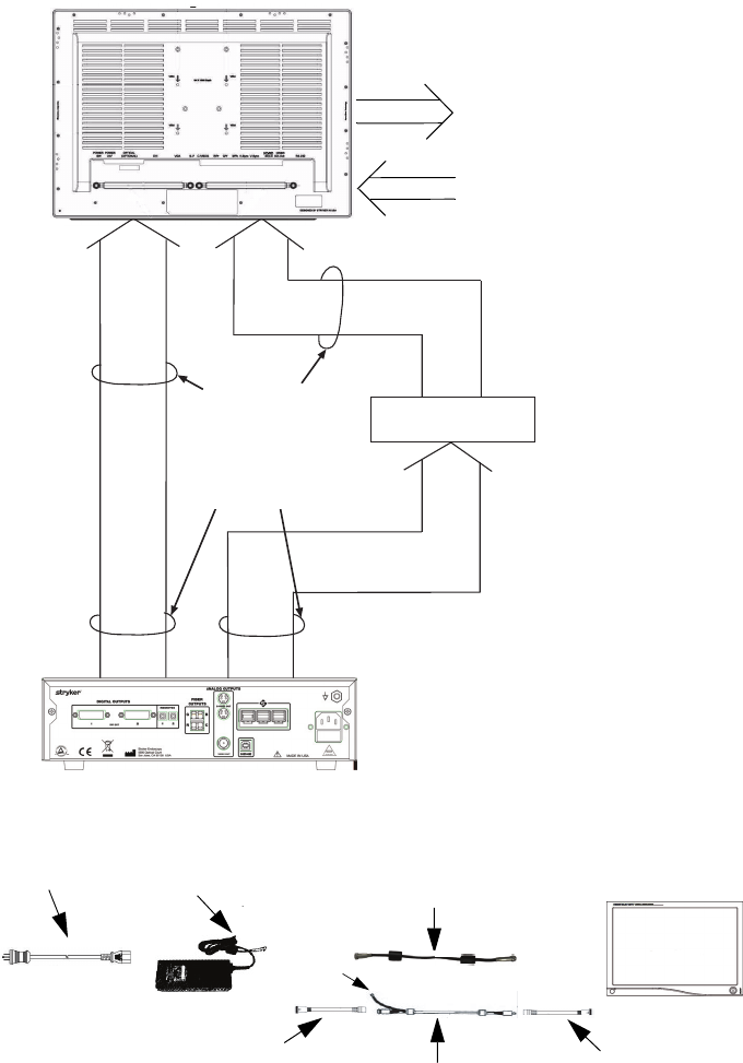
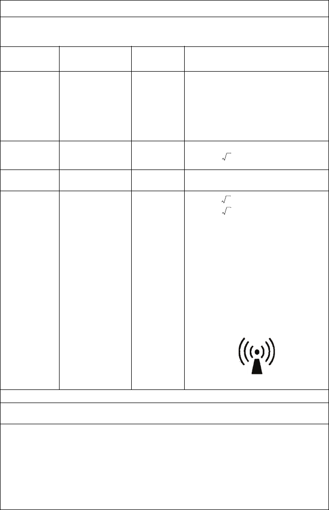
System Interconnection
Power Connection
Video Input Signals
eg:
SDC
SIDNE
VIDEO PRINTER
DVD/VCR
etc...
Video Sources:
Camera (1188 Series,
1088 Series, 988 Series)
Video Peripheral
Signal Output
DVI
RGBHV
S-Video
C-Video
(Model 240-030-930)
VISIONELECT
VISION ELECT HDTV
(Model 240-030-960)
Video Input Signals
Video Peripheral
Signal Output:
DVI
RGBHV
S-Video
C-Video
SDI
Fiber (Optional)
eg:SDC
SIDNE
VIDEO PRINTER
DVD/VCR
etc....
Video Sources: Camera (xx88 Series)
SD/HD-SDI
output
Additional Inputs:
RGBS
YPbPr
SD/HD-SDI
SOG
Hospital-grade
power cord
Power Supply 240-030-950
Manufacturer: JEC Korea
Model : JMW1150KA2400F07
Extension cord
Manufacturer: JEC Korea
Model : 1501047 (15Ft)
or 1501047001 (75Ft)
or 1501047002 (6Ft)
Stryker P/N: 240-030-951 (15Ft)
or 240-030-952 (75Ft)
Converter cord
Manufacturer: JEC Korea
Model : 1501055
Converter cord
Manufacturer: JEC Korea
Model : 1501055001
Connect to
cart chasis
Manufacturer: Nortra Cables
Model : 240-030-722 (15Ft)
or 240-030-932 (75Ft)
or
VISION ELECT HDTV
(Model 240-030-960)
9
English
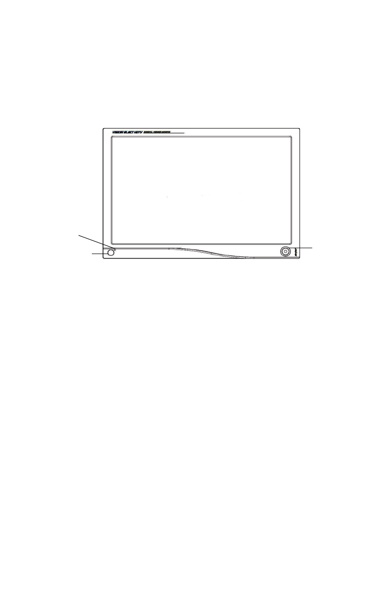
Operating the Monitor
Front Panel Controls
Operate the monitor using the rotary control located on the front panel.
A list of the monitor controls and their functions is provided below.
Figure 1: The VISION ELECT HDTV LCD Monitor front panel controls.
1. Power LED: Indicates menu current status. Displays green if
monitor is powered on, blinks if monitor is in Standby mode.
2. Power Switch (Soft): Turns the power ON or OFF.
3. Rotary Control (Turn Right / Left): With the on-screen display
menu activated, increases/decreases the value of the selected
parameter. With the on-screen display deactivated, activates the
video source selection menu.
4. Rotary Control Switch (Push): Accesses/selects on-screen
display menu.
5. Rotary Control Switch (Push and Hold): Exits on-screen
display menu.
Rotary
Control
Power LED
Power Switch
(Soft)
10
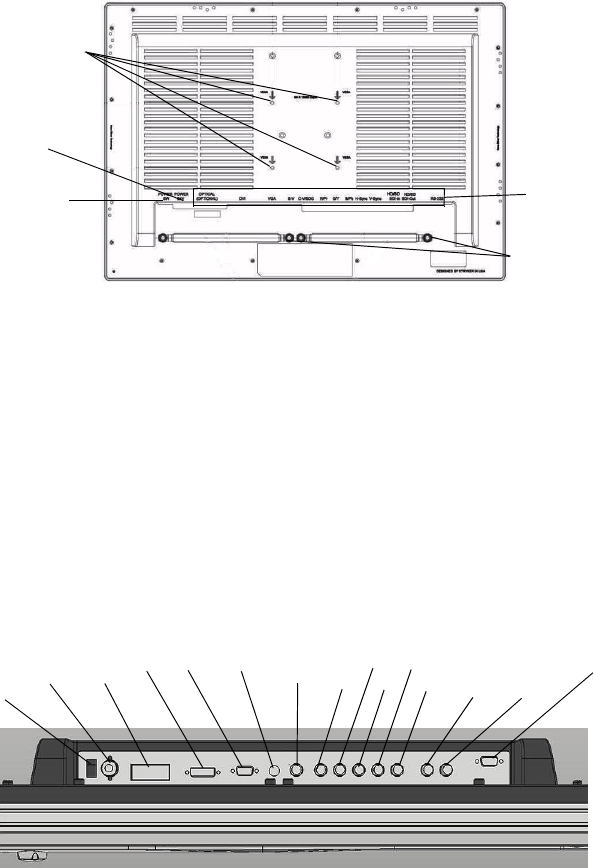
Rear Panel
Figure 2: The VISION ELECT HDTV LCD Monitor rear panel.
1. VESA mounting holes (100mm): Use to mount the monitior.
2. Power connector: DC power connector.
3. Power Switch (Hard): Turns the input DC power ON or OFF.
4. Connectors tag: Indicate types of connectors.
5. Cable Managerment Clamps: Cables organizer.
Cable
Managerment
Clamps
VESA
mounting holes
(100mm)
Power Switch
(Hard)
Connector
tags
Power
connector
Power
24V
Optical
(optional)
S-Video HD/SD
SDI
IN
G/Y H-sync
R/Pr B/Pb V-sync
Power
Switch
(hard)
DVI VGA C-Video/
SOG
HD/SD
SDI
OUT
RS232
Input Port Layout
11
English
Digital RGB
Analog RGB
Digital Optical*
HD/SD-SDI
Component (Y/Pb/Pr)
RGBS
S-Video
C-Video
SOG
Exit
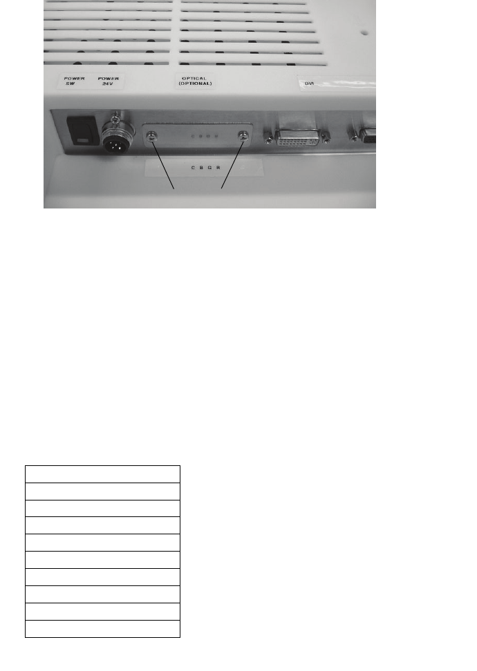
Fiber Optic Module (optional) installation/
Activation
1. Turn Off the monitor by Power Switch (Hard).
2. Unscrew the two screws over the cover plate, then remove the
cover plate.
3. Insert Fiber Optic Module (Stryker P/N 240-030-962) into the
Fiber Optical Module slot.
CAUTION: Excessive force or miss alignment during insertion might
damage the module connector.
4. Turn ON the monitor by Power Switch (Hard).
5. Turn OFF the monitor by Power Switch (Soft).
6. Press and hold the Power Switch (Soft) for 10 seconds to activate
the Fiber Optic input from the Input Selection menu.
Input Selection List
Unscrew those 2 screws
*Greyout if module not installed

12
Standard On-Screen Display (OSD) Operation
The monitor provides an on-screen display to help navigate through the
various monitor-adjustment menus.
1. Press the Rotary Control to activate the on-screen display (OSD)
menu.
2. Rotate the Rotary Control to move up or down through the menu.
The parameter will be highlighted when selected.
3. Press the Rotary Control to enter the next level OSD.
4. Rotate the Rotary Control to increase or decrease the value of
the selected parameter, or to make a selection on different
options.
5. To exit the OSD menu screen from the second- or third-level OSD
menu, select the Exit option. To completely exit the OSD, press
and hold the rotary control. If no keys are pressed for a time
period, the OSD automatically times out.
6. While the OSD menu is deactivated, rotate the Rotary Control to
activate the input signal selection menu. The current input signal
will be highlighted with a dot. Rotate the rotary control to select
the preferred input signal.
Stryker Camera Preset Modes
Camera Resolution
(H x V)
Horizontal
Frequency
(KHz)
Vertical
Frequency
(Hz)
988 1024 x 768 49.09 59.90
988i 1024 x 768 41.25 50.00
1088/SDC Pro2 1024 x 768 50.03 60.00
1088i/SDC Pro2 1024 x 768 41.10 50.00
1088/1188/SDC HD 1280 x 1024 64.02 60.10
1088i/1188i/SDC HD 1280 x 1024 59.99 50.00
1188w720 1280 x 720 45.00 60.00
1188iw720 1280 x 720 37.50 50.00

13
English
OSD Function Description
Actual on-screen display values may vary with updated versions of the firmware and user setting.
* Color Temperature RGB adjustment is avilable only for Standard, Arth and Lap settings.
* PACS and Norm selection only available under SOG input.
** Only available under SDI, S or C video input.
*** Only available under VGA input.
Item Function Description Range
Specialty
Color Temperature * Choose between color temperatures for Standard, Arth, Lap, PACS, or
Norm
Red Red balance -128 to 128
Green Green balance -128 to 128
Blue Blue balance -128 to 128
Gamma Gamma value 0.1 to 2.5, S0,
S1, S2
Setting
Brightness Increase or decrease the brightness 0-100
Contrast Increase or decrease the contrast 0-100
Phase** Increase or decrease the Phase level 0-100
Chroma** Increase or decrease the Chroma level 0-100
Image Sharpness Set image sharpness 1-10
Video Sharpness** Increase or decrease the video sharpness 0-100
Image Effect
Scale Mode Choose scale mode between Fill All, V-Fill, H-Fill, One To One or Fill To
Aspect
Freeze Frame Enable or Disable freeze frame
Zoom/Pan Enable zoom-in and pan function
PIP Enable PIP (Picture In Picture) function
POP Enable POP (Picture On Picture) function
PBP Enable PBP (Picture By Picture) function
Advanced
OSD Control Control OSD Menu Position, Background, and Timeout
Screen Control*** Control and adjust Horizontal, Vertical, Frequency, Phase
DPMS Choose DPMS (Display Power Management
Signaling)
ON, OFF, 60min,
90min, 120min
Auto Source Select Adjust Auto Source Select between on and off
Restore Factory
Settings Set to factory default
Key lock Set to Key lock mode
Information
User Name Entry Enter custom username display for boot-up display
Serial Number Display monitor serial number
Runtime Display current run time of monitor
Input Format Display current input format
14
Cleaning the Monitor
Caution Do not expose the monitor to moisture or directly
apply liquid cleaners directly to the screen. Spray the
cleaning solution into a soft cloth and clean gently.
Cleaning display plastic area
No specific liquid or chemical is necessary for cleaning the VISION
ELECT HDTV (model 240-030-960) LCD monitor. Use only non-abrasive
cloths and cleaning solutions to clean similar equipment used in hospitals.
1. Clean with a dry soft cloth, or a soft cloth lightly moistened with
mild detergent solution. Do not use any type of solvent, such as
alcohol or benzine, which might damage the finish.
2. Apply alcohol to glass surfaces with soft cotton applicator to aid in
cleaning and drying without leaving spots or streaks.
3. Dry thoroughly with soft towel or gauze surgical sponge.
Acceptable cleaning agents for bezel cleaning include:
• Cidex (2.4% glutaraldehyde solution)
• 0.5% Chlorhexidine in 70% isopropyl alcohol
Cleaning display filter area
Cleaning with a dry soft cloth, or soft cloth lightly moistened with warm
water. Other acceptable cleaning agents are listed below:
• 70% isopropyl alcohol
• Cidex (2.4% glutaraldehyde solution)
• 0.5% Chlorhexidine in 70% isopropyl alcohol

15
English
Troubleshooting
Before returning your LCD monitor for service, consult the
troubleshooting list below
Problem Current Status Remedy
No Picture
LED ON
Using the OSD, adjust the brightness and contrast
to maximum, or reset them to their default
settings.
LED OFF
Check the power switch at the front and the back
of monitor.
Check if the AC power cord is properly connected
to the AC adapter.
LED Blinking
Check if the video signal cable is properly
connected at the back of the monitor.
Check if power of the video signal source system
is ON.
Abnormal
Picture
Oversized,
undersized display,
missing display, or
center shift
Using the Screen Menu, adjust the PHASE,
FREQUENCY, HORIZONTAL, and VERTICAL
setting with non-standard video signal timing.
Wait a few seconds after initial sync of video
signals or power cycle the monitor.
16
Technical Specifications
Display
LCD Monitor Panel 25.54 inches
(a-Si TFT Active matrix LCD)
Synchronization 2.5 - 5.0 Vpp separated sync
Pixel Pitch 0.2865(W) x 0.2865(H)
Response Time <25ms Typ
View Angle +/-89° (L/R) × +/-89° (U/D)
Display Colors 16 million colors
Native Resolution 1920 dots × 1200 dots
Input Signal 1 x DVI
1 x VGA
1 x HD/SD-SDI
1 x C-Video/SOG
1 x S-Video
1 x Component (Y/G, Pb/B, Pr/
R, H/CS, VS)
1 x Optical (optional)
Maximum Pixel Clock 170MHz
Electrical
Power Adapter AC 100-240V; DC 24V
Power Consumption 150W (max)
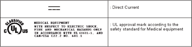
Current Direct
Dimensions
Dimensions (W × H × D) 616.4 x 428.8 x 121.2mm
Weight 19.62 lbs
VESA Mounting Interface VESA 100 x 100mm
Operating Conditions
Operating Temperature 41 to 90°F (5 to 32.2°C)
Relative Humidity 10 to 60%
Atmospheric Pressure Range 500 to 1060 hPa
Electrical Input Rating 24V DC 6.25A
Transport & Storage Conditions
Storage -4 to 140°F (-20 to 60°C)
Relative Humidity Range 10 to 85%
Atmospheric Pressure Range 500 to 1060 hPa
17
English
Classification and Approvals
Class I Equipment
Medical equipment with respect to electric shock, fire and mechanical
hazards only in accordance with UL 60601-1 and CAN/CSA C22.2
No. 601.1.
IPX1 Water Ingress Protection
Continuous operation
Warning This equipment is not suitable for use in the presence
of a FLAMMABLE ANESTHETIC MIXTURE WITH AIR, or
WITH OXYGEN OR NITROUS OXIDE.
This monitor is intended for use on Health Care Facilities model
240-030-960.
No user serviceable parts inside. Ask qualified personnel before
accessing internal components.
Caution For disposal of waste product, follow the requirement
of the local code.
This product is considered electronic equipment. It must not be disposed
of as unsorted municipal waste, and must be collected separately. Please
contact the manufacturer or other authorized disposal company to
decommission your equipment.
51 LJ
Medical Equipment
E215822

18
Electromagnetic Compatibility
Like other electrical medical equipment, the VISION ELECT HDTV
(model 240-030-960) monitor requires special precautions to ensure
electromagnetic compatibility with other electrical medical devices. To
ensure electromagnetic compatibility (EMC), the VISION ELECT HDTV
(model 240-030-960) monitor must be installed and operated according to
the EMC information provided in this manual.
Note The VISION ELECT HDTV (model 240-030-960) monitor
has been designed and tested to comply with IEC
60601-1-2:2003 requirements for EMC with other devices.
Caution The VISION ELECT HDTV (model 240-030-960) monitor
may be interfered with by other equipment, including
portable and mobile RF communication equipment,
even if such equipment meets the applicable
emissions requirements.
Warning Using cables or accessories other than those provided
with the VISION ELECT HDTV (model 240-030-960)
monitor, may result in increased electromagnetic
emissions or decreased immunity to such emissions.
Warning If the VISION ELECT HDTV (model 240-030-960)
monitor is used adjacent to or stacked with other
equipment, observe and verify normal operation of the
VISION ELECT HDTV (model 240-030-960) monitor in
the configuration in which it will be used prior to using
it in a surgical procedure. Consult the tables below for
guidance in placing the VISION ELECT HDTV (model
240-030-960) monitor
Warning When this device is connected with other electrical
equipment, leakage currents may be additive. To
minimize total leakage current per patient, ensure that
all systems are installed according to the requirements
of IEC 60601-1-1.

19
English
Manufacturer's declaration - electromagnetic emissions
VISION ELECT HDTV (model 240-030-960) monitor is intended for use in the electromagnetic
environment specified below. The customer or the user of VISION ELECT HDTV (model 240-030-
960) monitor should assure that it is used in such an environment.
Emissions test Compliance Electromagnetic Environment - guidance
RF emissions
CISPR11 Group 1
The VISION ELECT HDTV (model 240-030-
960) monitor must emit electromagnetic energy
in order to perform its intended function. Nearby
electronic equipment may be affected.
RF emissions
CISPR11 Class B
VISION ELECT HDTV (model 240-030-960)
monitor is suitable for use in all establishments,
including domestic establishments and those
directly connected to the public low-voltage
power supply network that supplies buildings
used for domestic purposes.
Harmonic emissions
IEC61000-3-2 Class D
Voltage Fluctuations/
flicker emissions
IEC61000-3-3
Complies

20
Manufacturer's declaration - electromagnetic immunity
VISION ELECT HDTV (model 240-030-960) monitor is intended for use in the electromagnetic
environment specified below. The customer or the user of VISION ELECT HDTV (model 240-030-960)
monitor should assure that it is used in such an environment.
Immunity Test IEC 60601
Test Level Compliance Level
Electromagnetic
environment -
guidance
Electrostatic Discharge
(ESD)
IEC61000-4-2
6kV contact
8kV air
6kV contact
8kV air
Floors should be
wood, concrete, or
ceramic tile. If floors
are covered with
synthetic material,
the relative humidity
should be at least
30%.
Electrical fast transient/
burst
IEC61000-4-4
2kV for power
supply lines
1kV for input/output
lines
2kV for power
supply lines
1kV for input/output
lines
Mains power quality
should be that of a
typical commercial or
hospital environment.
Surge
IEC61000-4-5
1kV differential
mode
2kV common mode
1kV differential
mode
2kV common mode
Mains power quality
should be that of a
typical commercial or
hospital environment.
Power frequency
(50/60Hz) magnetic field
IEC 61000-4-8
3.0 A/m 3.0 A/m
Power frequency
magnetic fields
should be at levels
characteristic of a
typical location in a
typical commercial or
hospital environment.
Voltage dips, short
interruptions and voltage
variations on power supply
input lines
IEC61000-4-11
<5% Ut (>95% dip
in Ut) for 0.5 cycle
40% Ut (60% dip in
Ut) for 5 cycles
70% Ut (30% dip in
Ut) for 25 cycles
<5% Ut (>95% dip
in Ut) for 5 sec.
<5% Ut (>95% dip
in Ut) for 0.5 cycle
40% Ut (60% dip in
Ut) for 5 cycles
70% Ut (30% dip in
Ut) for 25 cycles
<5% Ut (>95% dip
in Ut) for 5 sec.
Mains power quality
should be that of a
typical commercial or
hospital environment.
If the user of VISION
ELECT HDTV (model
240-030-960) image
intensifier requires
continued operation
during power mains
interruptions, it is
recommended that
VISION ELECT
HDTV (model 240-
030-960) image
intensifier be
powered from an
uninterruptible power
supply or a battery.
NOTE: Ut is the A.C. mains voltage prior to application of the test level.
21
English
Manufacturer's declaration - electromagnetic immunity
VISION ELECT HDTV (model 240-030-960) monitor is intended for use in the electromagnetic
environment specified below. The customer or the user of VISION ELECT HDTV (model 240-030-960)
monitor should ensure that it is used in such an environment.
Immunity Test IEC 60601
Test Level
Compliance
Level Electromagnetic Environment: Guidance
Portable and mobile RF communications
equipment should be used no closer to any
part of the VISION ELECT HDTV (model
240-030-960) monitor system, including
cables, than the recommended separation
distance calculated from the equation
applicable to the frequency of the
transmitter.
Conducted RF
IEC 61000-4-6
3 Vrms
150 kHz to 80 MHz 3 V
Recommended Separation Distance
Radiated RF
IEC 61000-4-3
3 V/m
80MHz to 2.5 GHz 3 V/m
80 MHz to 800 MHz
800 MHz to 2.5 GHz
where P is the maximum output power
rating of the transmitter in watts (W)
according to the transmitter manufacturer
and d is the recommended separation
distance in meters (m).
Field strengths from fixed RF transmitters,
as determined by an electromagnetic site
survey (a), should be less than the
compliance level in each frequency
range (b).
Interference may occur in the vicinity of
equipment marked with the following
symbol:
NOTE 1: At 80 MHz and 800 MHz, the higher frequency range applies.
NOTE 2: These guidelines may not apply in all situations. Electromagnetic propagation is affected by
absorption and reflection from structures, objects, and people.
(a) Field strengths from fixed transmitters, such as base stations for radio (cellular/cordless) telephones
and land mobile radios, amateur radio, AM and FM radio broadcast, and TV broadcast, cannot be
predicted theoretically with accuracy. To assess the electromagnetic environment due to fixed RF
transmitters, an electromagnetic site survey should be considered. If the measured field strength in the
location in which the VISION ELECT HDTV (model 240-030-960) monitor system is used exceeds the
applicable RF compliance level above, the VISION ELECT HDTV (model 240-030-960) monitor system
should be observed to verify normal operation. If abnormal performance is observed, additional
measures may be necessary, such as reorienting or relocating the VISION ELECT HDTV (model 240-
030-960) monitor unit.
(b) Over the frequency range 150 kHz to 80 MHz, field strengths should be less than 3 V/m.
d1.17P=
d1.17P=
d2.33P=
22
Recommended Separation Distances Between Portable and Mobile RF Communications
Equipment and the VISION ELECT HDTV (model 240-030-960) monitor System
The VISION ELECT HDTV (model 240-030-960) monitor system is intended for use in an
electromagnetic environment in which radiated RF disturbances are controlled. The user of the
VISION ELECT HDTV (model 240-030-960) monitor system can help prevent electromagnetic
interference by maintaining a minimum distance between portable and mobile RF communications
equipment (transmitters) and the VISION ELECT HDTV (model 240-030-960) monitor system as
recommended below, according to the maximum output power of the communications equipment.
Rated maximum output
power (W) of transmitter
Separation distance (m) according to frequency of transmitter
150 kHz to 80 MHz 80 MHz to 800 MHz 800 MHz to 2.5 GHz
0.01 0.12 0.12 0.23
0.1 0.37 0.37 0.74
1 1.17 1.17 2.33
10 3.70 3.70 7.37
100 11.70 11.70 23.30
For transmitters rated at a maximum output power not listed above, the recommended separation
distance (d) in meters (m) can be estimated using the equation applicable to the frequency of the
transmitter, where P is the maximum output power rating of the transmitter in watts (W) according to
the transmitter manufacturer.
NOTE 1: At 80 MHz and 800 MHz, the separation distance for the higher frequency range applies.
NOTE 2: These guidelines may not apply in all situations. Electromagnetic propagation is affected by
absorption and reflection from structures, objects, and people.
d1.17P=d1.17P=d2.33P=

ADVAN INT'L CORP.
47817 Fremont Blvd. Fremont, CA94538 U.S.A.
Tel: 510-490-1005 Fax: 510-490-1151
www.advancorp.com
2007/11 1000-401-075 A