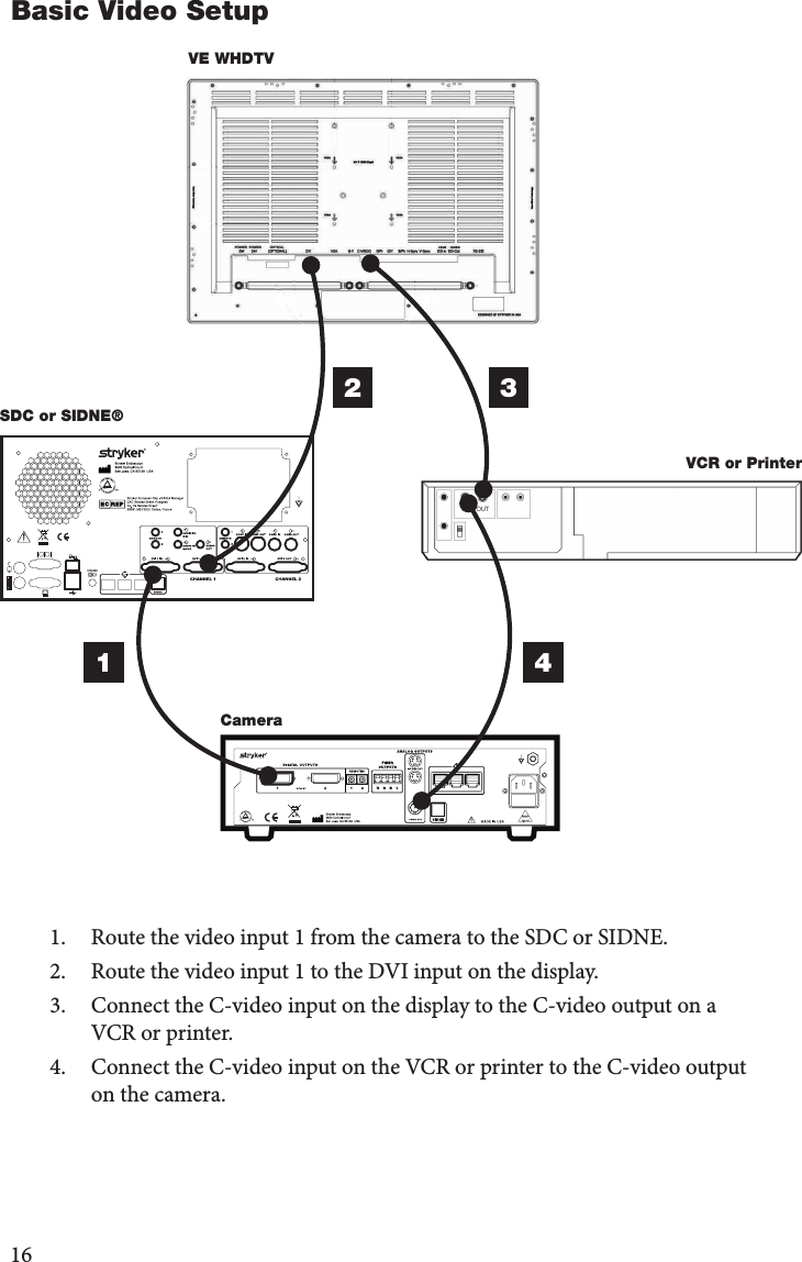
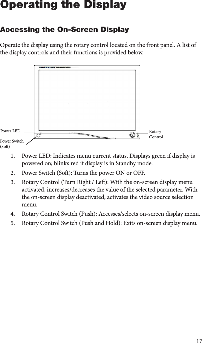
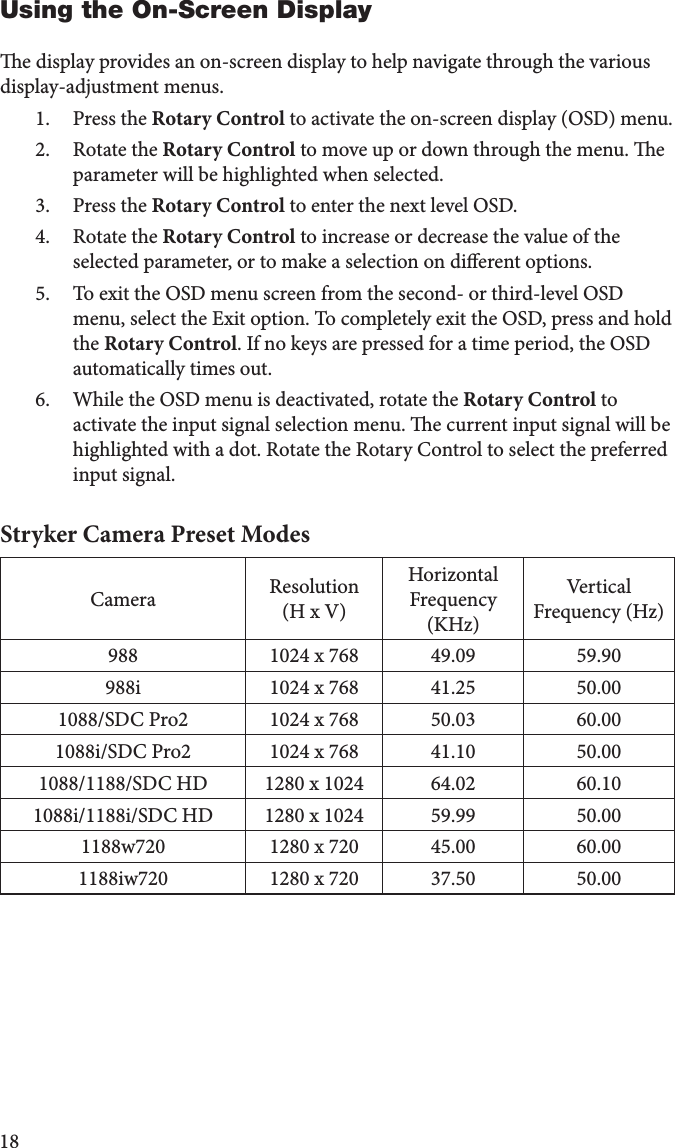
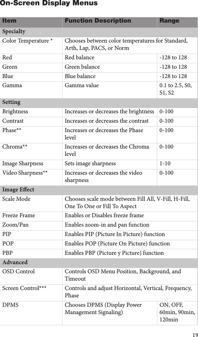
BARCO AMM260WTDSW 26" LCD Color Display User Manual

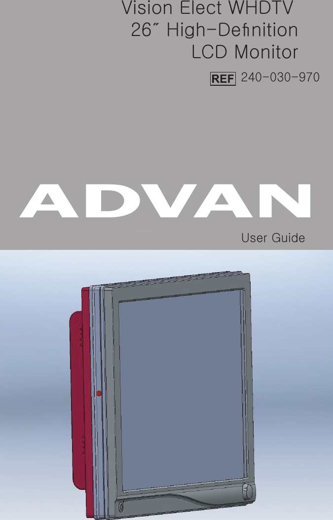
Advan Int'l Corp. 26" LCD Color Display

User Manual

Vision Elect WHDTV 26˝ High-DefinitionLCD Monitor240-030-970User GuideADVAN
ContentsWarnings and Cautions .................................................... 5Symbol Definitions .............................................................. 8Product Description ........................................................... 9Intended Use ...........................................................................9Indications/Contraindications ...............................................10Package Contents .................................................................11Device Features ....................................................................12Setup and Interconnection .......................................... 14Connection Ports ..................................................................14Connecting AC Power ...........................................................15Basic Video Setup .................................................................16Operating the Display ..................................................... 17Accessing the On-Screen Display ........................................17Using the On-Screen Display ................................................18On-Screen Display Menus ....................................................19  Cleaning and Maintenance .......................................... 27Maintenance ..........................................................................27Troubleshooting .................................................................. 28Technical Specifications ............................................... 29Electromagnetic Compatibility .................................. 32Warranty .................................................................................. 37Return Policy .........................................................................38 2121 22 23 25 30 31
5Warnings and CautionsPlease read this manual and follow its instructions carefully. e words warning, caution, and note carry special meanings and should be carefully reviewed:Warning  Indicates risks to the safety of the patient or user. Failure to follow warnings may result in injury to the patient or user. Caution  Indicates risks to the equipment. Failure to follow cautions may result in product damage. Note   Provides special information to clarify instructions or present additional useful information.An exclamation mark within a triangle is intended to alert the user to the presence of important operating and maintenance instructions in the manual. A lightning bolt within a triangle is intended to warn of the presence of hazardous voltage. Refer all service to authorized personnel. WarningsWarning To avoid potential serious injury to the user and the patient and/or damage to this device, please note the following warnings: 1.  Read the operating manual thoroughly and be familiar with its contents prior to using this equipment.2.  Carefully unpack the unit and check if any damage occurred during shipment.3.  Test this equipment prior to a surgical procedure. is display was fully tested at the factory before shipment.4.  Do not place the display or any other heavy object on the power cord. Damage to the cable can cause re or electric shock.5.  is equipment is not suitable for use in the presence of a ammable anesthetic mixture with air, or with oxygen or nitrous oxide.6.  Do not put any liquid or solid object into the panel. If this occurs, unplug the unit and have it checked by qualied personnel before operating it any further.7.  Unplug the unit if it is not to be used for an extended period of time. To
6disconnect the cord, unscrew the plug rst then, pull the cord out by the plug. Never pull the cord itself.8.  To avoid electric shock, avoid removing the control unit covers.9.  Do not attempt internal repairs or adjustments not specically detailed in this operating manual.10.  Pay close attention to the care and cleaning instructions in this manual. A deviation may cause damage (refer to the “Cleaning” section).11  Do not sterilize the display.12.  Use appropriate caution to prevent contact with uids if the unit is being used with a power supply in patient environments.13.  Federal law (United States of America) restricts this device to sale by, or on the order of, a physician.Cautions1.  Plug the AC adapter in to a grounded power outlet.2.  Use only the proprietary Vision Elect WHDTV power supply (P/N 240-030-950, Manufacturer: JEC Korea, Model No: JMW1150KA2400F07) for the Vision Elect WHDTV display (model 240-030-970). Completely 3.  Connect equipment to a receptacle labeled “Hospital Only” or “Hospital Grade” to achieve grounding reliability.4.  To connect to an international power supply, use an attachment plug appropriate for the power outlet5.  Power o the unit when it is not in use.6.  Remove the power module and connection when transporting the unit.8.  Handle the display with care. Do not strike or scratch the screen.9.  Never operate the unit right aer having been transported from a cold location directly to a warm location.10.  Do not expose the display to moisture or apply liquid cleaners directly to the screen. Spray the cleaning solution into a so cloth and clean gently.11.  Allow adequate air circulation to prevent internal heat buildup. 12.  Do not place the unit on surfaces (rugs, blankets, etc.) or near materials (curtains, draperies) that may block the ventilation slots. e display is cooled by natural convection and has no fan. 13.  Do not install the unit near sunlight, excessive dust, mechanical vibration, or shock.14.  Do not operate the unit in a vertical position. e unit is designed for operation in a horizontal position.
715.  Keep the unit away from equipment that uses strong magnets (i.e., large loudspeakers).16.  Do not touch the patient with signal input or output connectors. Equipment with SIP/SOP connectors should either comply with IEC 60601-1 and/or IEC 60601-1-1 harmonized national standards or the combination should be evaluated. 17.  CAUTION: Changes or modications not expressly approved by the party responsible for compliance could void the user’s authority to operate the equipment. Note  is equipment has been tested and found to comply with the limit for a Class B digital device, pursuant to Part 15 of the FCC Rules. ese limits are designed to provide reasonable protection against harmful interference in a residential installation. is equipment generates, uses, and can radiate radio frequency energy and, if not installed and used in accordance with the instructions, may cause harmful interference to radio communications. ere is no guarantee that interference will not occur in a particular installation, which can be determined by turning the equipment o and on. e user is encouraged to try to correct the interference by one or more of the following measures:•  Reorient or relocate the receiving device.•  Increase the separation distance between the equipment.•  Connect the equipment to an outlet on a circuit dierent from that to which the other device(s) are connected.•  Consult the manufacturer or eld service technician for help.18.  To ensure electromagnetic compatibility, refer to the “Electromagnetic Compatibility” section of this manual. e VISION ELECT WHDTV (model 240-030-970) display must be installed and operated according to the EMC information provided in this manual.e VISION ELECT WHDTV (model 240-030-970) display has been tested under the UL 60601-1 standard and is UL listed for medical application. e warranty is void if any of these warnings or cautions are disregarded.
8Symbol DefinitionsDangerous High VoltageConsult accompanying documentsDirect CurrentProtective earth groundFor indoor use onlyDC power control switchSerial NumberTop - BottomFragileDo not get wet3Maximum StackingManufacturerEuropean Authorized RepresentativeIndicates proof of conformity to applicable European Economic Community journal of the European CommunitiesMedical Equipment is in accordance with UL 60601-1 and CAN/CSA C22.2 Tested to comply with FCC Class B standardsIPX1 Degrees of protection against the ingress of water•DC power on at locker switchmust not be disposed as unsorted municipal waste and must be collected separately. Please contact the manufacturer or other authorized disposal company to decommission your equipment.
9Product Descriptione Vision Elect WHDTV (VE WHDTV) is a high-denition, widescreen LCD surgical display with a maximum resolution of WUXGA (1920 × 1200 at 60 Hz). e VE WHDTV supports various video inputs, including digital RGB, analog RGB, serial digital interface (SDI), component video (YPbPr/RGB), S-video, and C-video.Intended Usee VE WHDTV  is intended to display video images during the following types of surgical procedures:  •  arthroscopy (orthopedic surgery)•  laparoscopy (general and gynecological surgery)•  thoracoscopy•  endoscopy (general, gastroenterological, and ENT surgery)•  general surgery e VE WHDTV is intended for use by qualied general surgeons, gynecologists, urologists, thoracic, orthopedic, ENT, and plastic surgeons adequately trained in these surgical procedures. It is a non-sterile, reusable device, not intended for use in the sterile eld.
10Indications/Contraindicationse VE WHDTV is indicated for use as an accessory to an endoscopic  surgical camera during  general surgery, general laparoscopy, nasopharyngoscopy, ear endoscopy, sinusoscopy, and plastic surgery wherever a laparoscope/endoscope/arthroscope is indicated for use.Some  of the more common endoscopic surgeries where the VE WHDTV is indicated for use include: cholecystectomy; hernia repair; appendectomy; pelvic lymph node dissection; hysterectomy; laparoscopic and thoracoscopic anterior spinal fusion; anterior cruciate ligament reconstruction; knee, shoulder, and small-joint arthroscopy; decompression xation; wedge resection; exible endoscopy; urology and gynecology; lung and pleural biopsy; dorsal sympathectomy; pleurodesis; internal mammary artery dissection for coronary artery bypass; coronary artery bypass graing where endoscopic visualization is indicated; and examination of the evacuated cardiac chamber during performance of valve replacement .ere are no known contraindications.
11Package Contents(h)(g)(f)(e)(d)(c)(b)(a)(j)(i)a.  1 DVI cableb.  1 VGA HDDB15 cablec.  1 AC adapter (Stryker P/N 240-030-950,   Manufacturer: JEC, Model No: JMW1150KA2400F07)d.  1 Hospital-grade AC power corde.  4 M4 × 10mm VESA screwsf.  1 BNC cableg.  1 S-Video cableh.  2 Cable-management clampsi.  1 User guidej.   1 VE WHDTV display
12Device FeaturesFront panelOperate the display using the rotary control located on the front panel. A list of the display controls and their functions is provided below.12431.  Power LED Shines green if the display is powered on; blinks red if the display is in standby mode.2.  Power switch (so) Powers the display on and o3.  Rotary control Accesses the on-screen display and navigates through its functions.
13Rear panel125431.  Power connector Connects to the 24V DC power converter2.  Power switch (hard)  Powers on and o the input DC power3.  VESA mounting holes (100mm)Provide access points for mounting the monitor4.  Connector tags Indicate the types of video connectors.5.  Cable-management clampsOrganize cables
14Setup and InterconnectionStryker Endoscopy considers instructional training, or inservice, an integral part of the transmitter. Your local Stryker Endoscopy sales representative will perform at least one inservice at your convenience to help set up your equipment and instruct you and your sta on its operation and maintenance. To schedule an inservice, contact your local Stryker Endoscopy representative aer your equipment has arrived.Connection PortsVideo input signals are connected to the rear of the VE WHDTV display, as illustrated below:Power Switch (hard)RS232HD/SD SDI  INV-syncH-syncB/PbG/YR/PrC-Video SOGS-VideoVGADVIOptical (optional)Power 24 V HD/SD SDI  OUT.
15Connecting AC Power1321.  Connect the AC power, using the supplied hospital-grade power cord.2.  Connect the power cord to the power supply. (240-030-950, manufacturer: JEC Korea, model JMW1150KA2400F07)3.  Connect the power supply to the 24V input on the display.
16Basic Video Setup43SDC or SIDNE®CameraVCR or PrinterVE WHDTV211.  Route the video input 1 from the camera to the SDC or SIDNE.2.  Route the video input 1 to the DVI input on the display. 3.  Connect the C-video input on the display to the C-video output on a VCR or printer.4.  Connect the C-video input on the VCR or printer to the C-video output on the camera.
17Operating the DisplayAccessing the On-Screen DisplayOperate the display using the rotary control located on the front panel. A list of the display controls and their functions is provided below.Power LED Rotary ControlPower Switch (So)1.  Power LED: Indicates menu current status. Displays green if display is powered on; blinks red if display is in Standby mode.2.  Power Switch (So): Turns the power ON or OFF.3.  Rotary Control (Turn Right / Le): With the on-screen display menu activated, increases/decreases the value of the selected parameter. With the on-screen display deactivated, activates the video source selection menu.4.  Rotary Control Switch (Push): Accesses/selects on-screen display menu.5.  Rotary Control Switch (Push and Hold): Exits on-screen display menu.
18Using the On-Screen Displaye display provides an on-screen display to help navigate through the various display-adjustment menus.1.  Press the Rotary Control to activate the on-screen display (OSD) menu.2.  Rotate the Rotary Control to move up or down through the menu. e parameter will be highlighted when selected.3.  Press the Rotary Control to enter the next level OSD.4.  Rotate the Rotary Control to increase or decrease the value of the selected parameter, or to make a selection on dierent options.5.  To exit the OSD menu screen from the second- or third-level OSD menu, select the Exit option. To completely exit the OSD, press and hold the Rotary Control. If no keys are pressed for a time period, the OSD automatically times out.6.  While the OSD menu is deactivated, rotate the Rotary Control to activate the input signal selection menu. e current input signal will be highlighted with a dot. Rotate the Rotary Control to select the preferred input signal.Stryker Camera Preset ModesCamera Resolution (H x V)Horizontal Frequency (KHz)Vertical Frequency (Hz)988 1024 x 768 49.09 59.90988i 1024 x 768 41.25 50.001088/SDC Pro2 1024 x 768 50.03 60.001088i/SDC Pro2 1024 x 768 41.10 50.001088/1188/SDC HD 1280 x 1024 64.02 60.101088i/1188i/SDC HD 1280 x 1024 59.99 50.001188w720 1280 x 720 45.00 60.001188iw720 1280 x 720 37.50 50.00
19On-Screen Display MenusItem Function Description RangeSpecialtyColor Temperature * Chooses between color temperatures for Standard, Arth, Lap, PACS, or NormRed Red balance -128 to 128Green Green balance -128 to 128Blue Blue balance -128 to 128Gamma Gamma value 0.1 to 2.5, S0, S1, S2SettingBrightness Increases or decreases the brightness 0-100Contrast Increases or decreases the contrast 0-100Phase** Increases or decreases the Phase level0-100Chroma** Increases or decreases the Chroma level0-100Image Sharpness Sets image sharpness 1-10Video Sharpness** Increases or decreases the video sharpness0-100Image EectScale Mode Chooses scale mode between Fill All, V-Fill, H-Fill, One To One or Fill To AspectFreeze Frame Enables or Disables freeze frameZoom/Pan Enables zoom-in and pan functionPIP Enables PIP (Picture In Picture) functionPOP Enables POP (Picture On Picture) functionPBP Enables PBP (Picture y Picture) functionAdvancedOSD Control Controls OSD Menu Position, Background, and TimeoutScreen Control*** Controls and adjust Horizontal, Vertical, Frequency, PhaseDPMS Chooses DPMS (Display Power Management Signaling)ON, OFF, 60min, 90min, 120min
20Item Function Description RangeAuto Source Select Adjusts Auto Source Select between on and oRestore Factory SettingsSets to factory defaultKey lock Sets to Key lock modeWirelessMac ID Unique Machine ID of WHDTV TransmitterStatus Status MessageInformationUser Name Entry Enters custom username display for boot-up displaySerial Number Displays display serial numberRuntime Displays current run time of displayInput Format Displays current input formatActual on-screen display values may vary with updated versions of the rmware and user setting.*   Color Temperature RGB adjustment is available only for Standard, Arth and    Lap settings.*   PACS and Norm selection only available under SOG input.**   Only available under SDI, S, or C-video input.***   Only available under VGA input.
27Cleaning and MaintenanceCaution Do not expose the display to moisture or apply liquid cleaners directly to the screen. Spray the cleaning solution into a so cloth and clean the screen gently. No specic liquid or chemical is necessary for cleaning the VISION ELECT WHDTV (model 240-030-970) LCD display. Use only non-abrasive cloths and cleaning solutions to clean similar equipment used in hospitals.1.  Clean the plastic areas of the display with a dry so cloth, or a so cloth lightly moistened with mild detergent solution. Do not use any type of solvent, such as alcohol or benzine, which might damage the nish. Acceptable cleaning agents for bezel cleaning include:•  Cidex (2.4% glutaraldehyde solution)•  0.5% Chlorhexidine in 70% isopropyl alcohol2.  Apply alcohol to glass surfaces with so cotton applicator to aid in cleaning and drying without leaving spots or streaks.3.  Clean the display lter with a dry so cloth, or so cloth lightly moistened with warm water. Other acceptable cleaning agents are listed below:•  70% isopropyl alcohol•  Cidex (2.4% glutaraldehyde solution)•  0.5% Chlorhexidine in 70% isopropyl alcohol 4.  Dry thoroughly with so towel or gauze surgical sponge.Maintenancee VE WHDTV requires no periodic maintenance. ere are no user-serviceable parts inside. Refer all service questions to authorized Stryker service representatives.21
28TroubleshootingBefore returning your LCD display for service, consult the troubleshooting list below:Problem Current Status RemedyNo picture LED on Using the OSD, adjust the brightness and contrast to maximum, or reset them to their default settings.LED o Check the power switch at the front and back of the display.Check if the AC power cord is properly connected to the AC adapter.LED blinking Check if the video signal cable is properly connected at the back of the display.Check if power of the video signal source system is ON.AbnormalAbnormal picture Oversized, undersized, or missing display; or center shi.Using the Screen Menu, adjust the PHASE, FREQUENCY, HORIZONTAL, and VERTICAL settings with non-standard video signal timing.Wait a few seconds aer initial sync of video signals, or power cycle the display.OSD error message“No wireless channels available”Please turn o potential wireless interference, such as 802.11a/n access points and 5.8 GHz phonesOSD error message“Video format not supported”Ensure that an acceptable video source is connected. Refer to technical specications for a list of acceptable video formats.22
29Technical SpecificationsDisplay   LCD Display Panel 25.54 inches     (a-Si TFT Active matrix LCD)Synchronization 2.5 - 5.0 Vpp separated syncPixel Pitch    0.2865(W) × 0.2865(H)Response Time <25ms TypView Angle   +/-89° (L/R) × +/-89° (U/D)Display Colors 16 million colorsNative Resolution 1920 dots × 1200 dotsInput Signal 1 × DVI     1 × VGA     1 × HD/SD-SDI     1 × C-Video/SOG     1 × S-Video     1 × Component (Y/G, Pb/B, Pr/R, H/CS, VS)     1 × Optical (optional)     1 × Wireless (optional)Maximum Pixel Clock 170MHzElectrical    Power Adapter AC 100-240V; DC 24VPower Consumption 150W (max)Current DirectDimensions   Dimensions (W × H × D) 616.4 × 428.8 × 121.2mmWeight    19.62 lbsVESA Mounting Interface VESA 100 × 100mmOperating Conditions   Operating Temperature 41 to 90°F (5 to 32.2°C)Relative Humidity 10 to 60%Atmospheric Pressure Range  500 to 1060 hPaElectrical Input Rating 24V DC 6.25ATransport & Storage Conditions   Storage    -4 to 140°F (-20 to 60°C) Relative Humidity Range 10 to 85%Atmospheric Pressure Range  500 to 1060 hPaand ApprovalsClass I Equipmenthazards only in accordance with UL 60601-1 and CAN/CSA C22.2 No. 601.1.IPX1 Water Ingress Protection23 .
30Continuous operationis display is intended for use on Health Care Facilities model 240-030-970.24
32Electromagnetic CompatibilityLike other electrical medical equipment, the VISION ELECT WHDTV (model 240-030-970) requires special precautions to ensure electromagnetic compatibility with other electrical medical devices. To ensure electromagnetic compatibility (EMC), the display must be installed and operated according to the EMC information provided in this manual.Note  e VISION ELECT WHDTV (models 240-030-970 and -971) has been designed and tested to comply with IEC 60601-1-2:2001 requirements for EMC with other devices.Caution  Portable and mobile RF communications equipment may aect the normal function of the display.Caution  Do not use cables or accessories other than those provided with the display, as this may result in increased electromagnetic emissions or decreased immunity to such emissions.Caution  If the display is used adjacent to or stacked with other equipment, observe and verify normal operation of the display in the conguration in which it will be used prior to using it in a surgical procedure. Consult the tables below for guidance in placing the display.Warning When this device is connected with other electrical equipment, leakage currents may be additive. To minimize total leakage current per patient, ensure that all systems are installed according to the requirements of IEC 60601-1-1. 25
33Guidance and Manufacturer’s Declaration: Electromagnetic EmissionsThe Model 240-030-970 is intended for use in the electromagnetic environment specied below. The customer or the user of Model 240-030-970 should ensure that it is used in such an environment..Emissions test Compliance Electromagnetic Environment - guidanceRF emissions CISPR 11 Group 1Model 240-030-970 uses RF energy only for its internal function; therefore, its RF emissions are very low and are not likely to cause any interference in nearby electronic equipment.RF emissions CISPR 11 Class B The Model 240-030-970 is suitable for use in all establishments other than domestic establishments and those directly connected to the public low-voltage power supply network that supplies buildings used for domestic purposes, provided the following warning is heeded:Warning: This system is intended for use by healthcare professionals only. This sys-tem may cause radio interference or may disrupt the operation of nearby equipment. It may be necessary to take mitigation measures, such as reorienting or relocat-ing the system or shielding the location.Harmonic emissions IEC61000-3-2 Class DVoltage Fluctuations/ icker emissions IEC61000-3-3 Complies26
34Guidance and Manufacturer’s Declaration--Electromagnetic ImmunityModel 240-030-970 is intended for use in the electromagnetic environment specied below. The customer or the user of  Model 240-030-970 should ensure that it is used in such an environment.Immunity Test IEC 60601 Test LevelCompliance LevelElectromagnetic Environment-- GuidanceElectrostatic Discharge (ESD)IEC61000-4-26kV contact8kV air6kV contact8kV airFloors should be wood, concrete, or ceramic tile. If oors are covered with synthetic material, the relative humidity should be at least 30%.Electrical fast transient/burst IEC61000-4-42kV for power supply lines 1kV for input/output lines2kV line to ground1kV line to lineMains power quality should be that of a typical commercial or hospital environment.SurgeIEC61000-4-51kV differential mode2kV common mode1kV differential mode 2kV common modeMains power quality should be that of a typical commercial or hospital environmentVoltage dips, short interruptions and voltage variations on power supply input lines IEC61000-4-11<5% Ut (>95% dip in Ut) for 0.5 cycle40% Ut (60% dip in Ut) for 5 cycles70% Ut (30% dip in Ut) for 25 cycles<5% Ut (>95% dip in Ut) for 5 sec.<5% Ut (>95% dip in Ut) for 0.5 cycle40% Ut (60% dip in Ut) for 5 cycles70% Ut (30% dip in Ut) for 25 cycles<5% Ut (>95% dip in Ut) for 5 secMains power quality should be that of a typical commercial or hospital environment. If the user of Wireless Transmitter requires continued operation during power mains interruptions, it is recommended that Wireless Transmitter be powered from an uninterruptible power supply or a battery.Power frequency (50/60Hz) magnetic eldIEC 61000-4-83.0 A/m 3.0 A/mPower-frequency magnetic elds should be at levels characteristic of a typical location in a typical commercial or hospital environment.NOTE: Ut is the AC mains voltage prior to application of the test level.27
35Guidance and Manufacturer’s Declaration: Electromagnetic ImmunityModel 240-030-970 is intended for use in the electromagnetic environment specied below. The customer or the user of  Model 240-030-970 should ensure that it is used in such an environment.Immunity Test IEC 60601 Test levelCompliance LevelElectromagnetic  Environment - guidancePortable and mobile RF communications equipment should be used no closer to any part of the Wireless Transmitter system, including its cables, than the recommended separation distance calculated from the equation applicable to the frequency of the transmitter.Recommended Separation DistanceConducted RFIEC 61000-4-63 Vrms150 kHz to 80 MHz3 V d = 1.17√PRadiated RFIEC 61000-4-33 V/m80MHz to 2.5 GHz3 V/m d = 1.17√P  80 MHz to 800 MHzd = 2.33√P  800 MHz to 2.5 GHzwhere P is the maximum output power rating of the transmitter in watts (W) according to the transmitter manufacturer and d is the recommended separation distance in meters (m).Field strengths from xed RF transmitters, as determined by an electromagnetic site survey (a), should be less than the compliance level in each frequency range(b).Interference may occur in the vicinity of equipment marked with the following symbol:NOTE 1: At 80 MHz and 800 MHz, the higher frequency range applies.NOTE 2: These guidelines may not apply in all situations. Electromagnetic propagation is affected by absorption and reection from structures, objects, and people.(a) Field strengths from xed transmitters, such as base stations for radio (cellular/cordless) telephones and land mobile radios, amateur radio, AM and FM radio broadcast, and TV broadcast, cannot be predicted theoretically with accuracy. To assess the electromagnetic environment due to xed RF transmitters, an electromagnetic site survey should be considered. If the measured eld strength in the location in which the Model 240-030-970 system is used exceeds the applicable RF compliance level above, the Model 240-030-970 system should be observed to verify normal operation. If abnormal performance is observed, additional measures may be necessary, such as reorienting or relocating the Model 240-030-970 unit.(b) Over the frequency range 150 kHz to 80 MHz, eld strengths should be less than 3 V/m.28
36Recommended Separation Distances Between Portable and Mobile RF Communications Equipment and the Model 240-030-970 SystemThe Model 240-030-970 system is intended for use in an electromagnetic environment in which radiated RF disturbances are controlled. The user of the Model 240-030-970 system can help prevent electromagnetic interference by maintaining a minimum distance between portable and mobile RF communications equipment (transmitters) and the Model 240-030-970 system as recommended below, according to the maximum output power of the communications equipment..Rated maximum output power (W) of transmitterSeparation distance (m) according to frequency of transmitter150 kHz to 80 MHzd = 1.17√P80 kHz to 800 MHz d = 1.17√P800 kHz to 2.5 GHz d = 1.17√P0.01 0.12 0.12 0.230.1 0.37 0.37 0.7411.17 1.17 2.3310 3.70 3.70 7.37100 11.70 11.70 23.30For transmitters rated at a maximum output power not listed above, the recommended separation distance (d) in meters (m) can be estimated using the equation applicable to the frequency of the transmitter, where P is the maximum output power rating of the transmitter in watts (W) according to the transmitter manufacturer.NOTE 1: At 80 MHz and 800 MHz, the separation distance for the higher frequency range applies.NOTE 2: These guidelines may not apply in all situations. Electromagnetic propagation is affected by absorption and reection from structures, objects, and people.29
37WarrantyStryker Endoscopy warrants all products, subject to the exceptions provided herein, to be free from defects in design, materials and workmanship and to substantially conform to the product specications contained in the documentation provided by Stryker Endoscopy with the products for a period of one year from the date of purchase (the “Warranty Period”).  is warranty shall apply only to the original end-user purchaser of products directly from Stryker Endoscopy or a Stryker Endoscopy authorized distributor.  is warranty may not be transferred or assigned without the express written consent of Stryker Endoscopy.If a valid warranty claim is received within the Warranty Period, Stryker will, in its sole discretion: (1) repair the product at no charge, (2) replace the product at no charge with a product that is at least functionally equivalent to the original product, or (3) refund the purchase price of the product.  In any event, Stryker’s liability for breach of warranty shall be limited to the replacement value of the defective or non-conforming part or component.is warranty does not apply to: (1) products that have been misused, neglected, modied, altered, adjusted, tampered with, improperly installed or refurbished; (2) products that have been repaired by any person other than Stryker Endoscopy personnel without the prior written consent of Stryker Endoscopy; (3) products that have been subjected to unusual stress or have not been maintained in accordance with the instructions in the user manual or as demonstrated by a Stryker Endoscopy representative; (4) products on which any original serial numbers or other identication marks have been removed or destroyed; or (5) products that have been repaired with any unauthorized or non-Stryker components, including replacement lamps.If Stryker determines in its reasonable discretion that the claimed defect or non-conformance in the product is excluded from warranty coverage as described hereunder, it will notify the customer of such determination and will provide an estimate of the cost of repair of the product.  In such an event, any repair would be performed at Stryker’s standard rates.Products and product components repaired or replaced under this warranty continue to be warranted as described herein during the initial Warranty Period or, if the initial Warranty Period has expired by the time the product is repaired or replaced, for thirty (30) days aer delivery of the repaired or replaced product.  When a product or component is replaced, the item provided in replacement will be the customer’s property and the replaced item will be Stryker’s property.  If a refund is provided by Stryker, the product for which the refund is provided must be returned to Stryker and will become Stryker’s property.e inspection, testing, acceptance or use of the products and services furnished hereunder shall not aect Stryker’s obligation under this warranty, and such warranty shall survive inspection, test, acceptance and use.30
38Notwithstanding the above, the following products are warranted for a period of ninety (90) days from the date of purchase: Scopes, Fiber Optic Cables, VCRs, Displays, and Printers. Replacement light bulbs are warranted for a period of sixty (60) days from the date of purchase.TO THE FULLEST EXTENT PERMITTED BY LAW, THE EXPRESS WARRANTY SET FORTH HEREIN IS THE ONLY WARRANTY APPLICABLE TO THE PRODUCTS AND IS EXPRESSLY IN LIEU OF ANY OTHER WARRANTY BY STRYKER, EXPRESSED OR IMPLIED, INCLUDING, BUT NOT LIMITED TO, ANY IMPLIED WARRANTY OF MERCHANTABILITY OR FITNESS FOR A PARTICULAR PURPOSE. EXCEPT AS SPECIFICALLY PROVIDED IN THIS WARRANTY AND TO THE EXTENT PERMITTED BY LAW, STRYKER IS NOT RESPONSIBLE FOR INDIRECT, SPECIAL, INCIDENTAL OR CONSEQUENTIAL DAMAGES RESULTING FROM ANY BREACH OF WARRANTY OR UNDER ANY OTHER LEGAL THEORY.Return PolicyA Returned Merchandise Authorization (“RMA”) number must be obtained from Stryker Endoscopy before returning product.  To obtain an RMA number, please contact Stryker Endoscopy Customer Service at 1-800-624-4422.  Please send any returned products to: Stryker Endoscopy, Attn: Service Unit, 5900 Optical Court, San Jose, CA 95138.With the return, please include the RMA number, the applicable purchase order number, the original invoice number, the name, address, and account number of the organization returning the product, an itemization of the items being returned, and the reason for the return.  Please carefully package the product being returned.  Credit will not be given for items that are damaged in return shipment due to inadequate packaging.  Please clean and sterilize all potentially contaminated products prior to returning them to Stryker Endoscopy.  It is unlawful to transport bio-contaminated products through interstate commerce, unless they are properly packaged and labeled as such.  Stryker Endoscopy reserves the right to destroy contaminated product at the customer’s expense and charge the customer for a replacement unit.31
3932
ADVAN Int’l Corp.47817 Fremont Blvd.Fremont, CA 94538 USA1-510-490-10052008/06 1000401089 A

Navigation menu