BARCO AMM261WTDS 26 Inch LCD Monitor User Manual P22286A Book indb
Advan Int'l Corp. 26 Inch LCD Monitor P22286A Book indb
BARCO >
User manual
VisionPro 26” LED Display
0240-031-020
Table of Contents
Warnings and Cautions ............................................................................................1
About Your Device .....................................................................................................3
Intended Use ........................................................................................................................3
Indications .............................................................................................................................3
Contraindications ................................................................................................................3
Package Contents ...............................................................................................................4
Device Features....................................................................................................................5
Setup ............................................................................................................................9
Connections ..........................................................................................................................9
Basic Video Setup .............................................................................................................11
Operation ................................................................................................................. 12
On-Screen Display (OSD) ...............................................................................................12
OSD Menus .........................................................................................................................14
Troubleshooting ...............................................................................................................16
Cleaning and Maintenance ................................................................................... 17
Technical Speci cations ........................................................................................ 18
Symbols and De nitions ....................................................................................... 22

1
Warnings and Cautions
Please read this manual and follow its instructions carefully. The words warning, caution,
and note carry special meanings and should be carefully reviewed:
Warning: Indicates measures to avoid potential serious injury to the user and the patient
and/or damage to this device.
Caution: Indicates risks to the equipment. Failure to follow cautions may result in product
damage.
Note: Provides special information to clarify instructions or present additional useful
information.
Warnings
To avoid potential serious injury to the user and the patient and/or damage to this device, please
note the following warnings:
1. Read this manual thoroughly and be familiar with its contents prior to using this device.
2. Federal law (United States of America) restricts this device to sale by, or on the order of, a
physician.
3. Carefully unpack the device and check if any damage occurred during shipment.
4. This device is non-sterile and therefore should not be placed in the sterile eld.
5. Do not place the device or any other heavy object on the power cord. Damage to the cable
can cause re or electric shock.
6. To avoid electric shock, avoid removing the bezel.
7. This device should not be used adjacent to or stacked with other devices. If adjacent or
stacked use is necessary, the device should be observed to verify normal operation in the
con guration in which it will be used.
8. Test this device prior to a surgical procedure. This device was fully tested at the factory
before shipment.
9. Do not attempt internal repairs or adjustments not speci cally detailed in this manual.
Ensure that readjustments, modi cations, and/or repairs are carried out by persons
authorized by Stryker Endoscopy.
10. Do not put any liquid or solid object into the panel. If this occurs, unplug the device and
have it checked by quali ed personnel before operating it any further.
11. Use appropriate caution to prevent contact with uids if the device is being used with a
power supply in patient environments.
12. The use of cables and/or other accessories with this device, other than those speci ed, may
result in increased emissions or decreased immunity of this device.
Cautions
1. Connect the device to an AC adapter connected to a hospital grade power cord ensuring the
power cord is plugged into a grounded power outlet to achieve grounding reliability.
2. Do not sterilize the device, as the delicate electronics cannot withstand this procedure.
3. Use only the proprietary surgical display power supply for the display. Completely secure the
connection between the DC power cord and the extension cord.
2
4. Never operate the device immediately after transportation from a cold location to a warm
location.
5. To connect to an international power supply, use an attachment plug appropriate for the
cations" section of this manual.
6. Unplug the device if it is not to be used for an extended period of time. To disconnect the
rst, then pull the cord out by the plug. Never pull the cord itself.
7. Do not expose the device to moisture or apply liquid cleaners directly to the screen. Spray
the cleaning solution into a soft cloth and clean gently. For further detail, refer to the
"Cleaning and Maintenance" section of this manual.
8. Allow adequate air circulation to prevent internal heat buildup. Do not place the device
on surfaces (rugs, blankets, etc.) or near materials (curtains, draperies) that may block the
ventilation slots. The device is cooled by natural convection and has no fan.
9. Do not touch the patient with signal input or output connectors. Equipment with SIP/
national standards or the combination should be evaluated for safety.
10. To ensure electromagnetic compatibility, refer to the “Electromagnetic Compatibility” section
11. Pay close attention to the cleaning instructions in this manual. A deviation may cause
damage.
12. Do not install the device near sunlight, excessive dust, mechanical vibration, or shock.
cult to disconnect the power cord from the supply
mains.
14. Do not operate with the glass device screen facing downward.
15. Handle the device with care. Do not strike or scratch the screen.
cations not expressly approved by the party responsible for compliance
could void the user’s authority to operate the device.
The warranty is void if any of these warnings or cautions are disregarded.
This product contains electrical waste or electronic equipment. It must not be disposed of as
unsorted municipal waste and must be collected separately.
For a Class B digital device or peripheral, the instructions furnished the user shall include the
following or similar statement, placed in a prominent location in the text of the manual:
NOTE: This equipment has been tested and found to comply with the limits for a Class B digital
device, pursuant to part 15 of the FCC Rules. These limits are designed to provide reasonable
protection against harmful interference in a residential installation. This equipment generates,
uses and can radiate radio frequency energy and, if not installed and used in accordance with
the instructions, may cause harmful interference to radio communications. However, there is no
guarantee that interference will not occur in a particular installation. If this equipment does cause
harmful interference to radio or television reception, which can be determined by turning the
equipment o and on, the user is encouraged to try to correct the interference by one or more of
the following measures:
—Reorient or relocate the receiving antenna.
—Increase the separation between the equipment and receiver.
—Connect the equipment into an outlet on a circuit dierent from that to which the receiver
is connected.
—Consult the dealer or an experienced radio/TV technician for help.
(c) The provisions of paragraphs (a) and (b) of this section do not apply to digital devices exempted
from the technical standards under the provisions of § 15.103.
(d) For systems incorporating several digital devices, the statement shown in paragraph (a) or (b) of
this section needs to be contained only in the instruction manual for the main control unit.
(e) In cases where the manual is provided only in a form other than paper, such as on a computer
disk or over the Internet, the information required by this section may be included in the manual in
that alternative form, provided the user can reasonably be expected to have the capability to access
information in that form.
3
About Your Device
VisionPro 26” LED Display
REF: 0240-031-020
The VisionPro 26” LED Display is a wide screen LED surgical display that can support a maximum
resolution of WUXGA (1920x1200). The display supports various video inputs, including digital
RGB, analog RGB, serial digital interface (SDI), component video (YPbPr/RGBS), S-video, and
C-video.
Intended Use
The VisionPro 26” LED Display is intended for video display during surgical procedures.
Indications
This device is indicated for the following surgical procedures:
• Arthroscopy (orthopedic surgery)
• Laparoscopy (general and gynecological surgery)
• Thorascopy
• Endoscopy (general, gastroenterological and ENT)
• ENT
• Gynecology
• General surgery
The display is a non-sterile, reusable device not intended for use in the sterile eld. The display
is intended for use by quali ed physicians having complete knowledge of these surgical
procedures.
Contraindications
There are no known contraindications for this device.
4
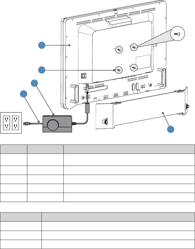
Package Contents
1
2
3
4
5
Reference Part Number Package Contents
1 0240-031-020 VisionPro 26” LED Display
2 – (4) M4 × 16 mm VESA screws
3 – Hospital-grade AC power cord
4 0240-031-004 Medical Power Supply
5 – Cable Cover
Part Number Optional Accessories
0240-031-002 VisionPro 26” Display Cover
0240-030-951 15-ft. (5 pin) DC extension cable
0240-030-952 75-ft. (5 pin) DC extension cable
5
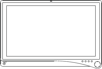
Device Features
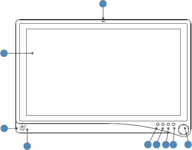
Front panel
Operate the display using the rotary control located on the front panel. A list of the display
controls and their functions is provided below.
2
3
45 8
7
6 9
1
1. Auxilliary device status
indicator
LED shines red to indicate an active connection to a
connected device.
2. Display Screen Shows video image.
3. Power switch (soft) Powers the display ON and OFF.
4. Power LED Indicates current status. Shines green if the display is
powered on or is in screen saver mode; blinks red if the
display is in sleep mode; blinks amber if over or under
voltage.
5. PIP Accesses the Picture in Picture adjustment menu.
6. Bright Accesses the Brightness adjustment menu
7. Specialty Accesses the Specialty adjustment menu
8. Input Accesses the Input selection menu
9. Rotary control Accesses the on-screen display and navigates through
its functions.
6
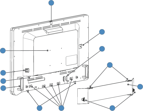
Rear panel
2
4
5
3
9
6
10
8
1
11
12
7
1. Accessory mount Provides an access point for mounting optional
accessories.
2. VESA mounting holes Provide access points for mounting the display.
3. Power switch (hard) Powers the input DC power ON and OFF.
4. Power connector Connects to the 24V DC power supply.
5. Handles Aid in display positioning.
Caution: The handles are not intended to bear the
entire weight of the display
6. Cable cover hinges Attach the bottom of the cable cover to the display.
7. Velcro straps Straps aid in cable management.
8. Cable cover thumbscrews Attach the cable cover to the display, and are
tightened or loosened using ngers.
9. Cable cover Covers and conceals cables.
10. Cable cover clips Attach the top of the cable cover to the display.
11. Cable wrap Provides a location for wrapping cables.
12. Locking feature A locking mechanism or cable may be routed here
for security purposes.
7
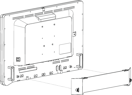
Cable Cover
Installing the Cable Cover
1. Align the left and right hinges of the cable cover onto the bottom rear of the display.
2. Snap on the top section of the cable cover to the aligning clips.
3. With your ngers, turn the thumbscrews clockwise to tighten and lock the cable cover
onto the display.
Removing the Cable Cover
1. With your ngers, turn the thumbscrews counterclockwise to loosen.
2. Once the thumbscrews are completely loosened, pinch the left and right clips and pull the
cable cover towards you.
3. Remove the cable cover from the left and right hinges.
8
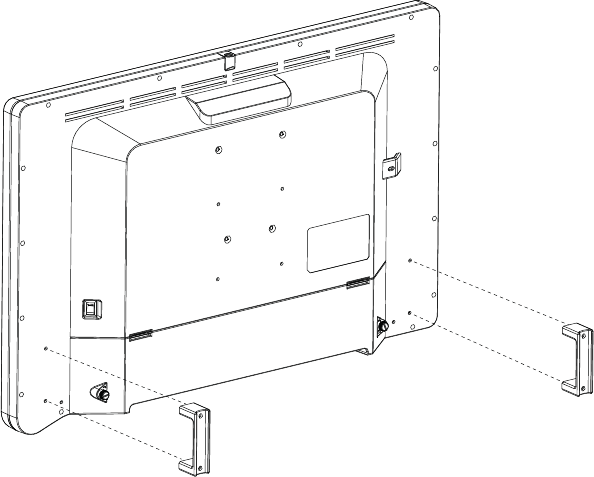
Display Handles
Caution: The handles are intended to aid in positioning the display, not for transporting the
display. The handles should not bear the full weight of the display.
Removing or Reinstalling the Display Handles
To Remove:
1. Using a 3mm hex key, loosen the two M4 x 30mm screws and gently pull the handle away
from the display.
To Reinstall:
1. Align the handle with the screw holes on the rear of the display.
2. Using a 3mm hex key, install the two M4 x 30mm screws to attach the handle.
9
Setup
Stryker Endoscopy considers instructional training, or inservice, an integral part
of this device. Your local Stryker Endoscopy sales representative will perform at
least one inservice at your convenience to help set up your device and instruct
you and your sta on its operation and maintenance. To schedule an inservice,
contact your local Stryker Endoscopy representative after your device has arrived.
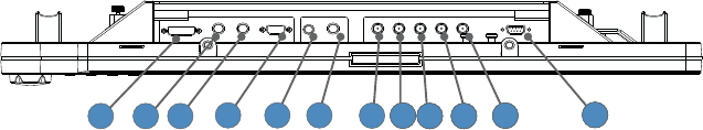
Connections
Connection Ports
Video input signals are connected to the rear of the display, as illustrated below:
1 2 3 4 5 6 66687 6669 66610 66611 66612
1. DVI
2. 3G/HD/SD
SDI-in
3. 3G/HD/SD
SDI-out
4. VGA
5. S-Video
6. C-Video/SOG
7. R/Pr
8. G/Y
9. B/Pb
10. H-sync
11. V-sync
12. RS232
10
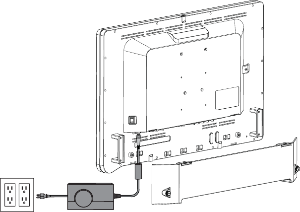
Connecting the Power Supply
1. Connect the power supply to the 24V input on the display.
2. Connect the AC power cord to the power supply*.
3. Connect the AC power, using the supplied hospital-grade power cord.
4. (Optional, not shown) Connect an extension cord between the power supply and display.
5. Install cable cover.
* Power supply
Model Number: BPM150S24F11
Manufacturer: Bridgepower Corp.
11
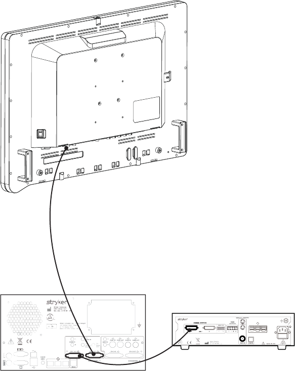
Basic Video Setup
1. Route the video output 1 from the camera to the SDC DVI input.
2. Route the video output 1 from the SDC DVI output to the DVI input on the display.
12
Operation
Operate the display using the rotary control and the four buttons located on the front panel. A list
of the display controls and their functions is provided below.
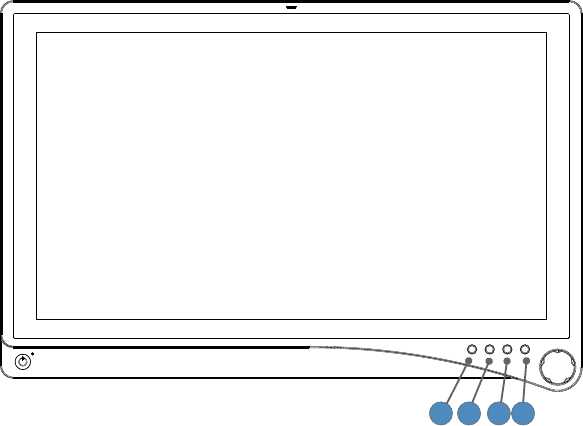
On-Screen Display (OSD)
Accessing the On-Screen Display
1 4
3
2
To use the four front-panel buttons:
Note: Use the Rotary Control to navigate the menus once they are activated.
1. PIP: Activates Picture Mode (Picture in Picture, Picture by Picture, Picture on Picture)
2. Bright: Activates the Brightness adjustment menu.
3. Specialty: Activates the Specialty adjustment menu.
4. Input: Activates the Input selection menu.
To use the Rotary Control:
• Push — Accesses/selects on-screen display menu.
• Turn Right/Left — With the on-screen display menu activated, turning increases/decreases
the value of the selected parameter.
• Push and Hold — Exits on-screen display menu.

13
Operating On-Screen Display
The device OSD helps navigate through various device menus.
1. Press the Rotary Control to activate the OSD menu.
2. Rotate the Rotary Control to move up or down through the menu.
The parameter will be highlighted when selected.
3. Press the Rotary Control to enter the next level OSD.
4. Rotate the Rotary Control to increase or decrease the value of the selected parameter, or to
make a selection on di erent options.
5. To exit the OSD menu screen from the second — or third — level OSD menu, select the
Exit option. To completely exit the OSD, press and hold the Rotary Control. If no keys are
pressed, the OSD will automatically exit after the factory-set predetermined time (the time is
customizable).
14
OSD Menus
Speciality
Menu Item Description Range
Color Temperature* Chooses between color temperatures for Lap A, Lap B,
Standard, Arthro, PACS, NORM, ENT, GYN.
—
Red Red balance -128–127
Green Green balance -128–127
Blue Blue balance -128–127
Gamma Gamma value 0.1–2.5,
S0, S1, S2
*Color Temperature RGB adjustment is available only for Standard, Arth, and Lap settings. PACS and
Norm adjustments are only avaliable under SOG input.
Brightness Settings
Menu Item Description Range
Brightness Increases or decreases the brightness 0–100
Contrast Increases or decreases the contrast 0–100
Phase** Increases or decreases the Phase level 0–100
Chroma** Increases or decreases the Chroma level 0–100
Image Sharpness Sets image sharpness 1–10
Video Sharpness** Increases or decreases the video sharpness 0–100
** Only available under SDI-, S-, or C-video input.
Image E ect
Menu Item Description
Scale Mode Chooses scale mode between Fill All, V-Fill, H-Fill, One-To-One, or
Fill-Aspect
Freeze Frame Enables or disables freeze frame
PIP Enables PIP (picture in picture) function
POP Enables POP (picture on picture) function
PBP Enables PBP (picture by picture) function
Advanced Settings
Menu Item Description
Key Lock Key lock on: Disables all key functions
Press and hold the rotary knob to turn o key lock.
15
Menu Item Description
Auto Source Select Scans inputs until an active video source is detected.
Sleep Timer On: The display enters sleep mode if no active video source is
detected.
O : The display will not enter sleep mode.
Timer: Set the time until the display enters sleep mode:
30, 60, 90, or 120 minutes.
OSD Control Controls OSD (On Screen Display) Menu Position, Background,
and Timeout
Restore Factory Settings Sets to factory default
Screen Control
VGA
• Horizontal
• Vertical
• Phase
• Frequency
S-Video,
C-Video,
SOG, RGBs,
Component
• Horizontal
• Vertical
Information
Menu Item Description
User Name Entry Enters custom user name display for boot-up display
Serial Number Displays device serial number
Runtime Displays current device total run time
Input Format Displays current input format
Note: Actual on-screen display values may vary with updated versions of the rmware
and user settings.

16
Troubleshooting
Before returning your display for service, consult the troubleshooting list below:
Problem Current Status Remedy
No picture Power LED on Using the OSD Menu, adjust the brightness
and contrast to maximum, or reset them to
their default settings.
Power LED o Ensure the power switch at the front and
rear of the display are set to ON.
Check if the AC power cord is properly
connected to the AC adapter and outlet.
Check that the power supply is fully
connected and functioning properly.
Power LED blinking Red Display is in sleep mode. Press
any key to wake the display.
Amber The power supply may be over or
under voltage.
Abnormal picture Oversized, undersized,
ormissing video; or
center shift.
Using the Screen Control Menu, adjust the
Phase, Frequency, Horizontal, and Vertical
settings in order to correct the display
image.
Adjust settings in Scale Mode
For VGA input only: push and hold the
rotary control for 1-2 seconds to re-sync the
video feed.
Wait a few seconds after initial sync of video
signals, or power cycle the display.
OSD error message “Out of Range” Ensure that an acceptable video source
is connected. Refer to the “Technical
Speci cations” section of this manual for a
list ofacceptable video formats.
17
Cleaning and Maintenance
Warning
To avoid electric shock and potentially fatal injury, unplug the display from the electrical
outlet before cleaning.
Caution
• Do not spray cleaning liquid directly onto the display as product damage may result.
Spray on the cloth before wiping the unit.
• Do not immerse the display in any liquid as product damage will result.
• Do not use corrosive cleaning solutions to clean the display as product damage may
result.
• Do not sterilize the display as product damage may result.
Cleaning
Should the unit need cleaning:
1. If the display cover is in place, remove the cover prior to cleaning.
2. Apply standard disinfectant or mild detergent to a dry sterile cloth.
3. Wipe the unit.
4. Take extra care when cleaning the screen. Excess liquid or drips that enter the bottom of the
screen may result in product damage.
Disposal
This product contains electrical waste or electronic equipment. It must not be
disposed of as unsorted municipal waste and must be collected separately in
accordance with applicable national or institutional related policies relating to
obsolete electronic equipment.
Dispose of any system accessories according to normal institutional practice relating to
potentially contaminated items.
18
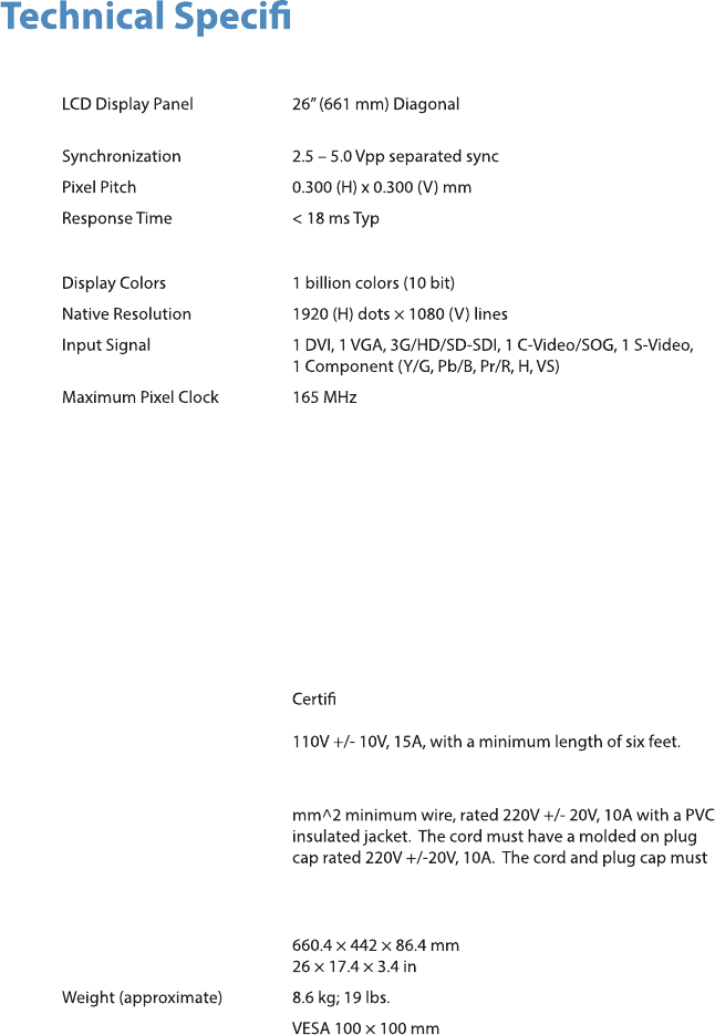
cations
Display
(a-Si TFT active matrix LCD)
Viewing Angle Right/Left/Up/Down 89 Degrees
Electrical
Power Adapter Input: 100 – 240 VAC; 50 – 60 Hz; 2.5 A
Output: 24V DC; 6.25A (150W Max)
Model Number: BPM150S24F11
Power Consumption
(approximate)
35 - 65 Watts
Current/Voltage Rating
Please ensure the respective power cord complies with applicable local regulations and
standards.
110V +/- 10V power
outlets
Select a power supply cord that is UL Listed and C.S.A
ed, type SJT or SVT, 3 – conductor, 18AWG,
terminated in a molded on hospital grade plug cap rated
220V +/- 20V power
outlets
Select a power supply cord that is internationally
harmonized and marked “<HAR>”, 3 – conductor, 0.75
be suitable for medical use.
Dimensions
Dimensions (W × H
× D)
VESA Mounting
Interface
Operating Conditions
Temperature Range
Relative Humidity
Range
41 – 104°F (5 – 40°C)
30 – 95%
Transport & Storage Conditions
19
Temperature Range
Relative Humidity Range
-0.4 – 140°F (-18 – 60°C)
15 – 90%
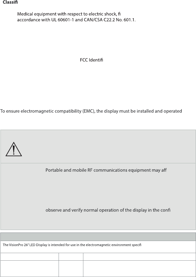
cation and Approvals
Class I Equipment
re, and mechanical hazards only in
IP23 Water Ingress Protection
Continuous Operation
Compliance
FCC Regulations FCC Part 15 Class B
er: QVXAMM261WTDS
Note: Please contact your local Stryker Endoscopy sales representative for information on
changes and new products.
Electromagnetic Compatibility
Like other electrical medical equipment, the VisionPro 26” LED Display requires special
precautions to ensure electromagnetic compatibility with other electrical medical devices.
according to the EMC information provided in this manual. The display has been designed and
tested to comply with IEC 60601-1-2 requirements for EMC with other devices.
Warning
When this device is connected with other electrical equipment, leakage
currents may be additive. To minimize total leakage current per patient,
ensure that all systems are installed according to the requirements of
IEC 60601-1-1.
Caution
ect the
normal function of the display.
Do not use cables or accessories other than those provided with the
display, as this may result in increased electromagnetic emissions or
decreased immunity to such emissions.
If the display is used adjacent to or stacked with other equipment,
guration
in which it will be used prior to using it in a surgical procedure. Consult
the tables below for guidance in placing the display.
Guidance and Manufacturer’s Declaration: Electromagnetic Emissions
ed below. The customer or the
user of the display should ensure it is used in such an environment.
ecnadiug - tnemnorivnE citengamortcelEecnailpmoCtset snoissimE
RF emissions CISPR 11 Group 1 The VisionPro 26” LED Display uses RF energy only for its internal
function; therefore, its RF emissions are very low and are not likely to
cause any interference in nearby electronic equipment.

20
RF emissions CISPR 11 Class B The VisionPro 26” LED Display is suitable for use in all establishments
other than domestic establishments and those directly connected to
the public low-voltage power supply network that supplies buildings
used for domestic purposes, provided the following warning is heeded:
Warning: This system is intended for use by health care professionals
only. This system may cause radio interference or may disrupt the
operation of nearby equipment. It may be necessary to take mitigation
measures, such as reorienting or relocating the system or shielding the
location.
Harmonic emissions IEC61000-3-2 Class D
Voltage Fluctuations/ icker
emissions IEC61000-3-3
Complies
Guidance and Manufacturer’s Declaration — Electromagnetic Immunity
The VisionPro 26” LED Display is intended for use in the electromagnetic environment speci ed below. The customer or the
user of the display should ensure that it is used in such an environment.
Immunity Test IEC 60601 Test Level Compliance Level Electromagnetic Environment--
Guidance
Electrostatic
Discharge (ESD)
IEC61000-4-2
± 6kV contact
± 8kV air
± 6kV contact
± 8kV air
Floors should be wood, concrete,
or ceramic tile. If oors are covered
with synthetic material, the relative
humidity should be at least 30%.
Electrical fast
transient/burst
IEC61000-4-4
± 2kV for power supply lines
± 1kV for input/output lines
± 2kV line to ground
± 1kV line to line
Mains power quality should be that
of a typical commercial or hospital
environment.
Surge
IEC61000-4-5
± 1kV di erential mode
± 2kV common mode
± 1kV di erential mode
± 2kV common mode
Mains power quality should be that
of a typical commercial or hospital
environment
Voltage dips, short
interruptions and
voltage variations
on power supply
input lines
IEC61000-4-11
• <5% UT (>95% dip in Ut)
for 0.5 cycle
• 40% UT (60% dip in Ut) for
5 cycles
• 70% UT (30% dip in Ut) for
25 cycles
• <5% UT (>95% dip in Ut)
for 5 sec.
• <5% UT (>95% dip in Ut)
for 0.5 cycle
• 40% UT (60% dip in Ut) for
5 cycles
• 70% UT (30% dip in Ut) for
25 cycles
• <5% UT (>95% dip in Ut)
for 5 sec
Mains power quality should be
that of a typical commercial or
hospital environment. If the user of
the transmitter requires continued
operation during power mains
interruptions, it is recommended
that the Wireless Transmitter be
powered from an uninterruptible
power supply or a battery.
Power frequency
(50/60Hz) magnetic
eld
IEC 61000-4-8
3.0 A/m 3.0 A/m Power-frequency magnetic
elds should be at levels
characteristic of a typical location
in a typical commercial or hospital
environment.
Note: UT is the AC mains voltage prior to application of the test level.
21
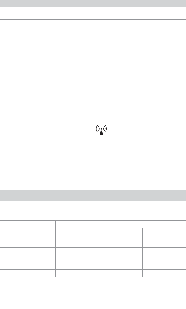
Guidance and Manufacturer’s Declaration: Electromagnetic Immunity
The VisionPro 26” LED Display is intended for use in the electromagnetic environment speci ed below.
The customer or the user of the display should ensure that it is used in such an environment.
Immunity Test IEC 60601 Test level Compliance Level Electromagnetic Environment - Guidance
Portable and mobile RF communications equipment should
be used no closer to any part of theVisionPro 26” LED Display,
including its cables, than the recommended separation
distance calculated from the equation applicable to the
frequency of the transmitter.
Recommended Separation Distance:
Conducted RF
IEC 61000-4-6
3 Vrms
150 kHz to 80 MHz
3 V d = 1.17√P
Radiated RF
IEC 61000-4-3
3 V/m
80MHz to 2.5 GHz
3 V/m d = 1.17√P 80 MHz to 800 MHz
d = 2.33√P 800 MHz to 2.5 GHz
where P is the maximum output power rating of the
transmitter in watts (W) according to the transmitter
manufacturer and d is the recommended separation distance
in meters (m).
Field strengths from xed RF transmitters, as determined by
an electromagnetic site survey (a), should be less than the
compliance level in each frequency range(b).
Interference may occur in the vicinity of equipment marked
with the following symbol:
NOTE 1: At 80 MHz and 800 MHz, the higher frequency range applies.
NOTE 2: These guidelines may not apply in all situations. Electromagnetic propagation is a ected by absorption and re ection
from structures, objects, and people.
(a) Field strengths from xed transmitters, such as base stations for radio (cellular/cordless) telephones and land mobile radios,
amateur radio, AM and FM radio broadcast, and TV broadcast, cannot be predicted theoretically with accuracy. To assess
the electromagnetic environment due to xed RF transmitters, an electromagnetic site survey should be considered. If the
measured eld strength in the location in which the VisionPro 26” LED Display is used exceeds the applicable RF compliance
level above, the display and transmitter should be observed to verify normal operation. If abnormal performance is observed,
additional measures may be necessary, such as reorienting or relocating the VisionPro 26” LED Display.
(b) Over the frequency range 150 kHz to 80 MHz, eld strengths should be less than 3 V/m.
Recommended Separation Distances Between Portable and Mobile RF Communications Equipment
and the VisionPro 26” LED Display
The VisionPro 26” LED Display is intended for use in an electromagnetic environment in which radiated RF disturbances are
controlled. The user of the VisionPro 26” LED Display can help prevent electromagnetic interference by maintaining a minimum
distance between portable and mobile RF communications equipment (transmitters) and the VisionPro 26” LED Display as
recommended below, according to the maximum output power of the communications equipment.
Rated maximum output power (W)
of transmitter
Separation distance (m) according to frequency of transmitter
150 kHz to 80 MHz
d = 1.17√P
80 kHz to 800 MHz
d = 1.17√P
800 kHz to 2.5 GHz
d = 1.17√P
0.01 0.12 0.12 0.23
0.1 0.37 0.37 0.74
1 1.17 1.17 2.33
10 3.70 3.70 7.37
100 11.70 11.70 23.30
For transmitters rated at a maximum output power not listed above, the recommended separation distance (d) in meters (m)
can be estimated using the equation applicable to the frequency of the transmitter, where P is the maximum output power
rating of the transmitter in watts (W) according to the transmitter manufacturer.
Note 1: At 80 MHz and 800 MHz, the separation distance for the higher frequency range applies.
Note 2: These guidelines may not apply in all situations. Electromagnetic propagation is a ected by absorption and re ection
from structures, objects, and people.
22
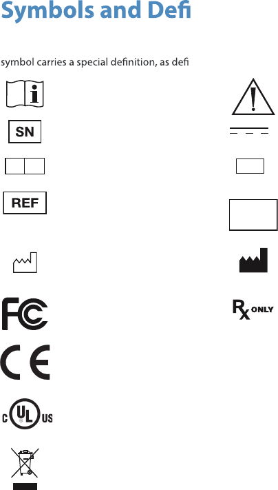
nitions
The following symbols appear on the product, its labeling, or the product packaging. Each
ned below:
Consult Instructions for Use Attention: See Instructions for Use
Serial Number Direct Current
EC REP Authorized European
Representative
QTY Quantity
Catalog number Made in
Korea Country of Origin
Date of Manufacture Legal manufacturer
Tested to comply with FCC
Class B standards
Federal law restricts this device
to sale by or on the order of a
physician
Complies with the
requirements of directive
93/42/EEC
This p
Medical Equipment is in accordance with UL 60601-1 and CAN/CSA C22.2 No. 601
in regards to electric shock, re hazards, and mechanical hazards.
roduct contains electrical waste or electronic equipment. It must not be
disposed of as unsorted municipal waste and must be collected separately.
IP23 Degrees of protection against the
ingress of water
23
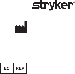
Produced for:
Stryker Endoscopy
5900 Optical Court
San Jose, CA 95138 USA
1-408-754-2000, 1-800-624-4422
www.stryker.com
European Representative:
Regulatory Manager, Stryker France
ZAC Satolas Green Pusignan
Av. De Satolas Green
69881 MEYZIEU Cedex, France
P22286A
2013/02