BARCO AMM320ES LCD Color Medical Monitor User Manual
Advan Int'l Corp. LCD Color Medical Monitor
BARCO >
User manual
1
32” 4K Surgical Display
240-031-050

2
Warning and Cautions
Please read this manual and follow its instructions carefully. The words warning, caution, and note carry special
meanings and should be carefully reviewed:
Warning: Indicates measures to avoid potential serious injury to the user and the patient.
Caution: Indicates risks to the equipment. Failure to follow cautions may result in product damage.
Note: Provides special information to clarify instructions or present additional useful information.
Warnings
To avoid potential serious injury to the user and the patient, please note the following warnings:
1. Read this manual thoroughly and be familiar with its contents prior to using this device.
2. Federal law (United States of America) restricts this device to sale by, or on the order of, a physician.
3. Carefully unpack the device and check if any damage occurred during shipment.
4. This device is non-sterile and therefore should not be placed in the sterile field.
5. Do not place the device or any other heavy object on the power cord. Damage to the cable can cause fire or electric
shock.
6. To avoid electric shock, avoid removing the bezel.
7. This device should not be used adjacent to or stacked with other devices. If adjacent or stacked use is necessary, the
device should be observed to verify normal operation in the configuration in which it will be used.
8. Test this device prior to a surgical procedure. This device was fully tested at the factory before shipment.
9. Do not attempt internal repairs or adjustments not specifically detailed in this manual. Ensure that readjustments,
modifications, and/or repairs are carried out by persons authorized by Stryker Endoscopy.
10. Do not put any object into the panel. If this occurs, unplug the device and have it checked by qualified personnel
before operating it any further.
11. Use appropriate caution to prevent contact with fluids if the device is being used with a power supply in patient
environments.
12. The use of cables and/or other accessories with this device, other than those specified, may result in increased
emissions or decreased immunity of this device.
13. AC adapter is not protected against water. DO NOT expose AC adapter to water
3
Cautions
1. Connect the device to an AC adapter connected to a hospital grade power cord ensuring the power cord is plugged
into a grounded power outlet to achieve grounding reliability.
2. Do not sterilize the device, as the delicate electronics cannot withstand this procedure.
3. Use only the proprietary surgical display power supply for the display. Completely secure the connection between the
DC power cord and the extension cord.
4. Never operate the device immediately after transportation from a cold location to a warm location.
5. To connect to an international power supply, use an attachment plug appropriate for the power outlet
6. Unplug the device if it is not to be used for an extended period of time. To disconnect the cord, unscrew the plug first,
then pull the cord out by the plug. Never pull the cord itself.
7. Do not expose the device to moisture or apply liquid cleaners directly to the screen. Spray the cleaning solution onto a
soft cloth and clean gently. For further detail, refer to the "Cleaning and Maintenance" section of this manual.
8. Allow adequate air circulation to prevent internal heat buildup. Do not place the device on surfaces (rugs, blankets,
etc.) or near materials (curtains, draperies) that may block the ventilation slots. The device is cooled by natural
convection and has no fan.
9. Do not touch the patient with signal input or output connectors. Equipment with SIP/SOP connectors should either
comply with IEC 60601-1 and/or IEC 60601-1-1 harmonized national standards or the combination should be evaluated
for safety.
10. To ensure electromagnetic compatibility, refer to the “Electromagnetic Compatibility” section of this manual. The 32”
4K Surgical Display (240-031-050) must be installed and operated according to the EMC information provided in this
manual.
11. Pay close attention to the cleaning instructions in this manual. A deviation may cause damage.
12. Do not install the device near sunlight, excessive dust, mechanical vibration, or shock.
13. Do not position the device so that it is difficult to disconnect the power cord from the supply mains.
14. Do not operate with the glass device screen facing downward.
15. Handle the device with care. Do not strike or scratch the screen.
16. Changes or modifications not expressly approved by the party responsible for compliance could void the user’s
authority to operate the device.
17. Note: This device has been tested and found to comply with the limit for a Class B digital device, pursuant to Part
15 of the FCC Rules. These limits are designed to provide reasonable protection against harmful interference in a
residential installation. This device generates, uses, and can radiate radio frequency energy and, if not installed and
used in accordance with the instructions, may cause harmful interference to radio communications. There is no
guarantee that interference will not occur in a particular installation, which can be determined by turning the device
off and on. The user is encouraged to try to correct the interference by one or more of the following measures:
• Reorient or relocate the receiving device.
• Increase the separation distance between the device.
4
• Connect the device to an outlet on a circuit different from that to which the other device(s) are connected.
• Consult the manufacturer or field service technician for help.
The warranty is void if any of these warnings or cautions is disregarded.
This product contains electrical waste or electronic equipment. It must not be disposed of as unsorted municipal waste
and must be collected separately.
5
About Your Device
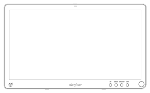
32” 4K Surgical Display
REF: 240-031-050
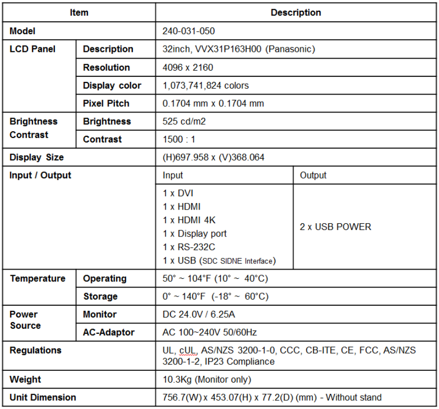
32” 4K Surgical Display is 32” LED Display is a wide screen LED surgical display that can support a maximum resolution of
UHD (4096 x 2160). The display supports the following video inputs: digital RGB (DVI), HDMI and HDMI (4K). It supports
serial communication via the RS232 port and SDC SIDNE port. It also supports USB ports (2) for 5V, 1A power supply for
accessories and peripherals.
Intended Use
32” 4K Surgical Display is intended for video display during surgical procedures. The display is a non-sterile reusable
device not intended for use in the sterile field. The display is intended for use by qualified physicians having complete
knowledge of these surgical procedures.
Indications for Use
General Surgical Population
Contraindications:
There are no known contraindications for this device.
6
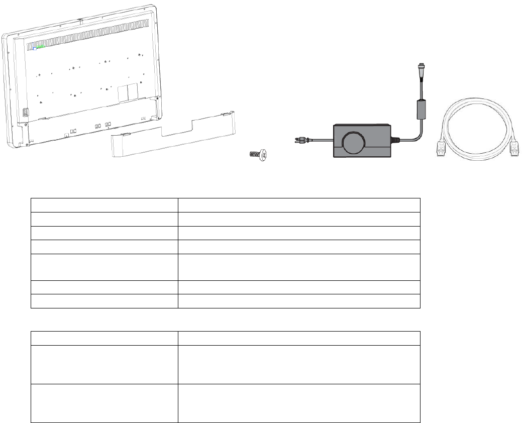
Package Contents
x4
Part Number
Package Contents
240-031-050
32” 4K Surgical Display
-
(4) M4 x 16mm VESA screws
-
Hospital-grade AC power cord
0240-031-004
Medical Power Supply
Model : BPM150S24F11 (Bridgepower)
-
HDMI Cable
-
Cable Cover
Part Number
Optional Accessories
0240-030-951
15-ft. (5 pin) DC extension cable
Model: 1501047***(Bridgepower) ***: blank or
001~999
0240-030-952
75-ft. (5 pin) DC extension cable
Model: 1501047***(Bridgepower) ***: blank or
001~999
7
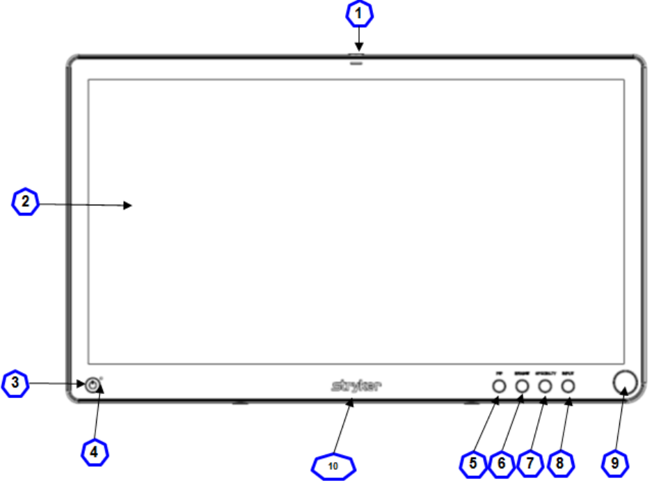
Device Features
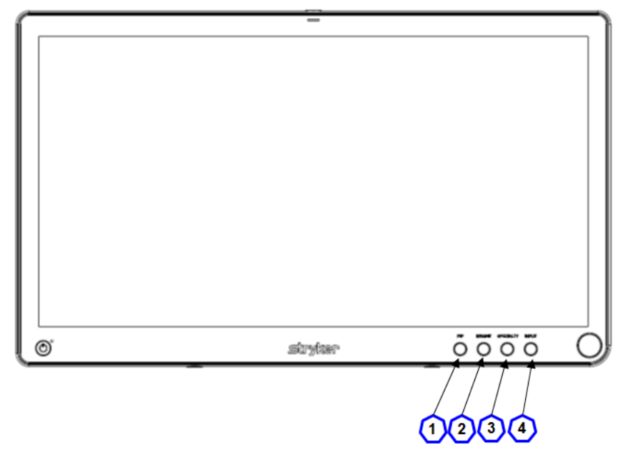
Front panel
1. Auxiliary device status LED shines red to indicate an active connection to a connected device
2. Display Screen Shows video image
3. Power switch(soft) Powers the display ON and OFF.
4. Power LED* Indicates current status
5. PIP Accesses the Picture in Picture adjustment menu.
6. Bright Accesses the Brightness adjustment menu.
7. Specialty Accesses the Specialty selection menu.
8. Input Access the Input selection menu.
9. Rotary control Access the on-screen and navigates through its function.
10. Logo Light Indicates current status.
*: Refer to following Power management menu

8
This system saves energy by switching your monitor into a low-mode when is has not been used for a certain period of
time. Power Management system operates with a VESA DPMS compliant video card installed in your computer. You use
a software utility installed on your computer to set up this feature.
State
Normal
Operation
DPMS Standby
DPMS suspend
DPM Off
Horizontal Sync
Active
Inactive
Active
Inactive
Vertical Sync
Active
Active
Inactive
Inactive
Video
Active
Blanked
Blanked
Blanked
Power LED
GREEN
Green Flashing
Green Flashing
Green Flashing
Logo Light
White
Breathing Light
Breathing Light
Breathing Light
Power
Consumption
TBD
TBD
TBD
TBD
NOTE : This monitor automatically returns to normal operation when horizontal and vertical sync return. This occurs
when you move the computer’s mouse or press a key on the keyboard.
9
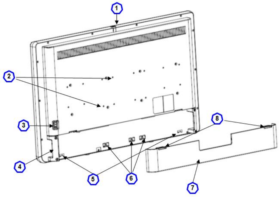
Rear Panel
1. Accessory mount Provide an access point for mounting optional accessories.
2. VESA mounting holes Provide access point for mounting the display. (100x100, 200x100)
3. Power switch (hard) Powers the input DC power On and OFF.
4. Handles Aid in display positioning
Caution: The handles are not intended to bear the entire weight of the display.
5. Cable cover hinges Attach the bottom of the cable cover to the display
6. Velcro straps Straps aid in cable management.
7. Cable cover Covers and conceals cables.
8. Cable cover clips Attach the top of the cable cover to the display.
10
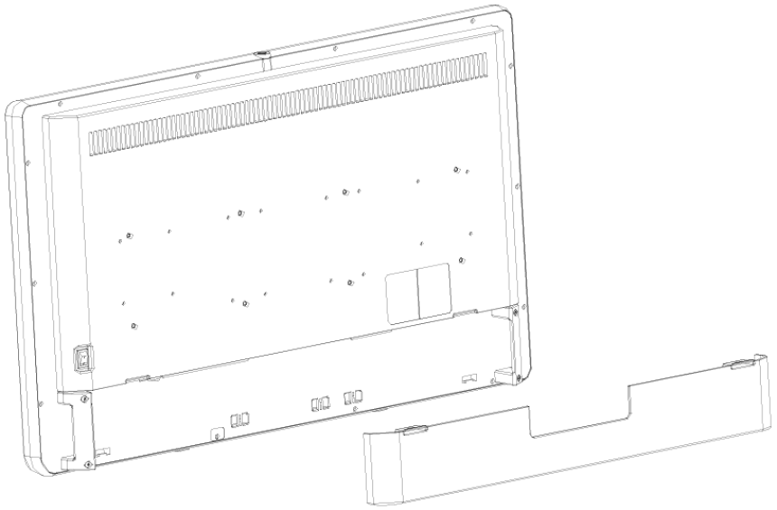
Cable Cover
Installing the Cable Cover
1. Align the left and right hinges of the cable cover onto the bottom rear of the display.
2. Snap on the top section of the cable cover to the aligning clips.
Removing the Cable Cover
1. Pinch the left and right clips and pull the cable cover towards you.
2. Remove the cable cover from the left and right hinges.
11
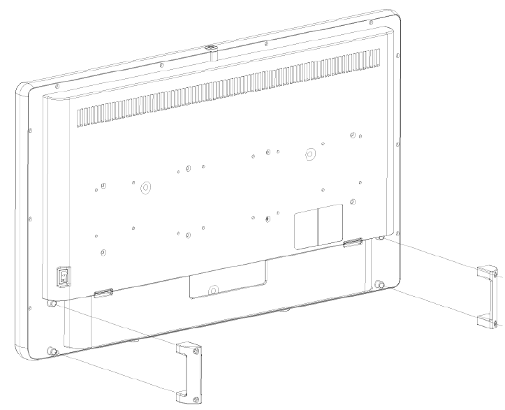
Display Handles
Caution: The handles are intended to aid in positioning the display, not for transporting the display. The handles
should not bear the full weight of the display.
Removing the Display Handles
1. Using a 3mm hex key, loosen the two M4 x 25mm screws and gently pull the handle away from the display.
Installing the Display Handles
1. Align the handle with the screw holes on the rear of the display.
2. With using a 3mm hex key, install the two M4 x 25mm screws to attach the handle.
12
Setup
Stryker Endoscopy considers instructional training, or inservice, an integral part of this device. Your local Stryker
Endoscopy sales representative will perform at least one inservice at your convenience to help set up your device and
instruct you and your staff on its operation and maintenance. To schedule an inservice, contact your local Stryker
Endoscopy representative after your device has arrived.
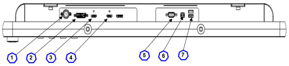
Connections
32” 4K Surgical Display Connection Ports
Video input and output signals are connected to the rear of the display, as illustrated below:
1. Power Connector (24V)
2. DVI
3. HDMI
4. HDMI 4K
5. RS-232
6. SDC SIDNE
7. ACC POWER
13
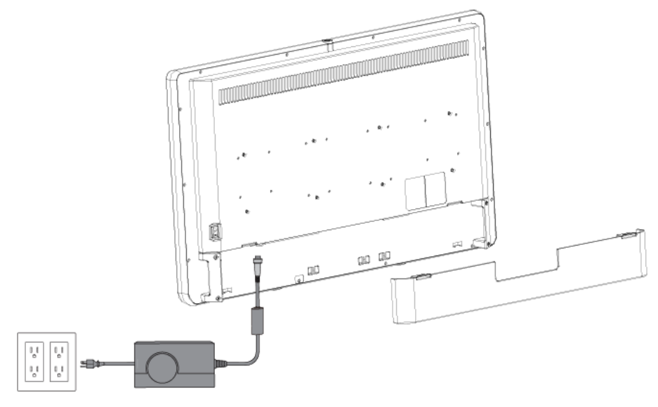
Connecting the Power Supply
1. Connect the power supply to the 24V input on the display
2. Connect the AC power cord to the power supply*.
3. Connect the AC power, using the supplied hospital-grade power cord.
4. (Optional, not shown) Connect an extension cord between the power supply and display.
5. Install cable cover.
* Power supply information: Model Number: BPM150S24F11, Manufacturer: Bridgepower Corp.
14
Operation
Operate the display using the rotary control and the four buttons located on the front panel. A list of the display controls
and their functions is provided below.
On-Screen Display (OSD)
Accessing the On-Screen Display
To use the four front-panel buttons:
1. PIP: Press to activate Picture Mode (Picture in Picture, Picture by Picture, Picture on Picture)
2. Bright: Activates the Brightness adjustment menu.
3. Specialty: Activates the Specialty adjustment menu.
4. Input: Activates the Input selection menu.
Use the Rotary Control to navigate the on-screen menus once they are activated:
• Push — Accesses/selects on-screen display menu.
• Turn Right/Left — With the on-screen display menu activated, turning increases/decreases the value of the selected
parameter.
• Push and Hold — Exits on-screen display menu.
15
Operating On-Screen Display
The device OSD helps navigate through various device menus.
1. Press the Rotary Control to activate the OSD menu.
2. Rotate the Rotary Control to move up or down through the menu.
The parameter is highlighted when selected.
3. Press the Rotary Control to enter the next level OSD.
4. Rotate the Rotary Control to increase or decrease the value of the selected parameter, or to make a selection on
different options.
5. To exit the OSD menu screen from the second or third level OSD menu, select the Exit option. To completely exit the
OSD, press and hold the Rotary Control. If no keys are pressed, the OSD will automatically exit after the factory-set
predetermined time (the time is customizable).
16
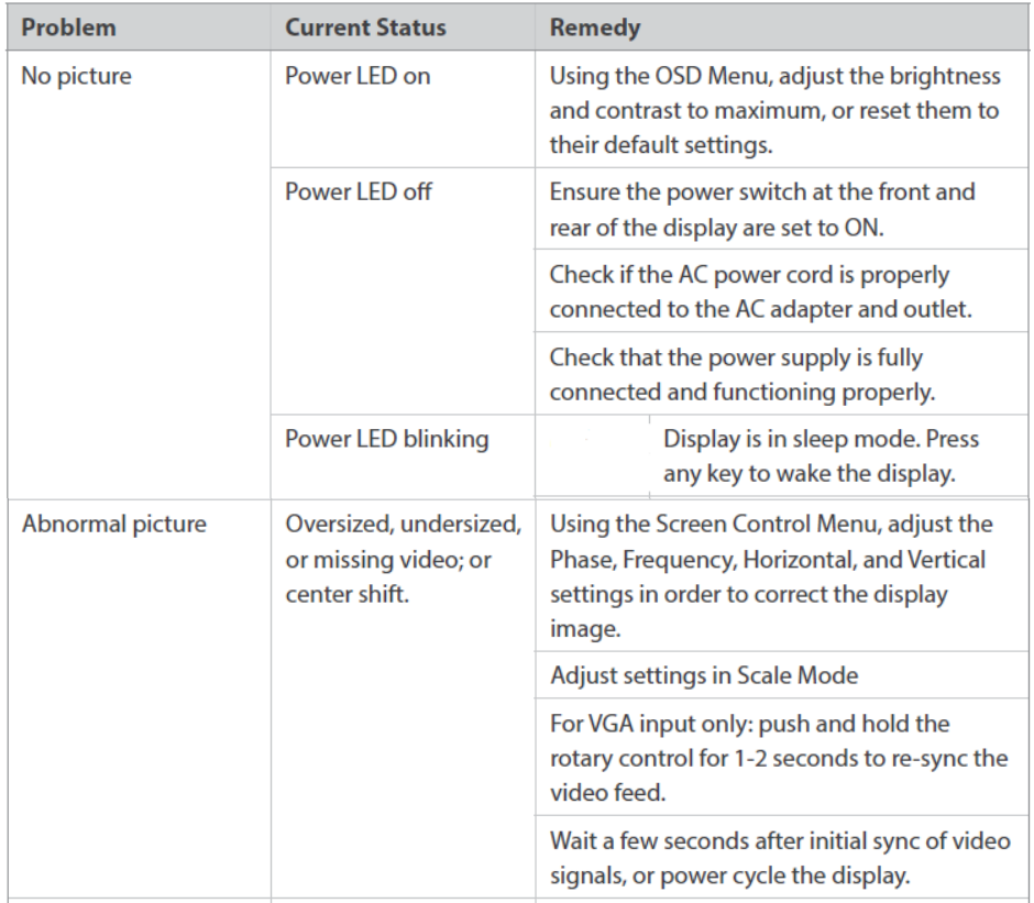
Troubleshooting
Before returning your display for service, consult the troubleshooting list below:

17
Cleaning and Maintenance
Warning
To avoid electric shock and potentially fatal injury, unplug the display and power supply from the electrical outlet before
cleaning.
Caution
• Do not spray cleaning liquid directly onto the display or the power supply as product damage may result. Spray on the
cloth before wiping the unit.
• Do not immerse the display or power supply in any liquid as product damage will result.
• Do not use corrosive cleaning solutions to clean the display or power supply as product damage may result.
• Do not sterilize the display or power supply as product damage may result.
Cleaning
To clean the display or the power supply:
1. If the display cover is in place, remove the cover prior to cleaning.
2. Apply standard disinfectant or mild detergent to a dry sterile cloth.
3. Wipe the display or power supply.
4. Take extra care when cleaning the display screen. Excess liquid or drips that enter the bottom of the screen or the
power supply receptacle may result in product damage.
Disposal
This product contains electrical waste or electronic equipment. It must not be disposed of as unsorted municipal
waste and must be collected separately in accordance with applicable national or institutional related policies relating to
obsolete electronic equipment.
Dispose of any system accessories according to normal institutional practice relating to potentially contaminated items.
18
Technical Specification
General Description
Classification and Approvals
Class 1 Equipment
Medical equipment with respect to electric shock, fi re, and mechanical hazards only in accordance with ANSI/AAMI
ES60601-1 and CAN/CSA C22.2 No. 60601.1.
IP23: Protection against access to hazardous parts from fingers or similar objects, protection from ingress of spraying
water (less than 60° from vertical)
Continuous Operation
Compliance
FCC Regulations: FCC Part 15 Class B
FCC Identifier: QVXAMM320ES
19
Electromagnetic Compatibility
Like other electrical medical equipment, 32” 4K Surgical Display requires special precautions to ensure
electromagnetic compatibility with other electrical medical devices. To ensure electromagnetic compatibility
(EMC), the display must be installed and operated according to the EMC information provided in this manual.
The display has been designed and tested to comply with IEC 60601-1-2 requirements for EMC with other
devices.
Warning
When this device is connected with other electrical equipment, leakage currents may be
additive. To minimize total leakage current per patient, ensure that all systems are
installed according to the requirements of IEC 60601-1-1.
Caution
Portable and mobile RF communications equipment may affect the normal function of the
display.
Do not use cables or accessories other than those provided with the display, as this may
result in increased electromagnetic emissions or decreased immunity to such emissions.
If the display is used adjacent to or stacked with other equipment, observe and verify
normal operation of the display in the configuration in which it will be used prior to using
it in a surgical procedure. Consult the tables below for guidance in placing the display.
Guidance and Manufacturer’s Declaration: Electromagnetic Emissions
32” 4K Surgical Display is intended for use in the electromagnetic environment specified below. The customer or
the user of the display should ensure it is used in such an environment.
Emissions test
Compliance
Electromagnetic Environment -
guidance
RF emissions CISPR 11
Group 1
The display use RF energy only for
their internal function; therefore,
their RF emissions are very low and
are not likely to cause any
interference in nearby electronic
equipment.
RF emissions CISPR 11
Class B
The display is suitable for use in all
establishments other than
domestic establishments and those
directly connected to the public
low-voltage power supply network
that supplies buildings used for
domestic purposes, provided the
following warning is heeded:
Warning: This system is intended
for use by health care professionals
only. This system may cause radio
interference or may disrupt the
operation of nearby equipment. It
may be necessary to take
mitigation measures, such as
reorienting or relocating the
system or shielding the location.
Harmonic emissions IEC61000-3-2
Class D
Voltage Fluctuations/ flicker
emissions IEC61000-3-3
Complies

20
Guidance and Manufacturer’s Declaration: Electromagnetic Immunity
32” 4K Surgical Display is intended for use in the electromagnetic environment specified below. The customer or
the user of the display should ensure that it is used in such an environment.
Immunity Test
IEC 60601 Test Level
Compliance Level
Electromagnetic
Environment Guidance
Electrostatic Discharge
(ESD)
IEC61000-4-2
± 6kV contact
± 8kV air
± 6kV contact
± 8kV air
Floors should be wood,
concrete, or ceramic tile.
If floors are covered with
synthetic material, the
relative humidity should
be at least 30%.
Electrical fast
transient/burst
IEC61000-4-4
± 2kV for power supply
lines
± 1kV for input/output
lines
± 2kV line to ground
± 1kV line to line
Mains power quality
should be that of a typical
commercial or hospital
environment.
Surge
IEC61000-4-5
± 1kV differential mode
± 2kV common mode
± 1kV differential mode
± 2kV common mode
Mains power quality
should be that of a typical
commercial or hospital
environment
Voltage dips, short
interruptions and voltage
variations on power
supply input lines
IEC61000-4-11
• <5% UT (>95% dip in UT)
for 0.5 cycle
• 40% UT (60% dip in UT)
for
5 cycles
• 70% UT (30% dip in UT)
for
25 cycles
• <5% UT (>95% dip in UT)
for 5 sec.
• <5% UT (>95% dip in UT)
for 0.5 cycle
• 40% UT (60% dip in UT)
for
5 cycles
• 70% UT (30% dip in UT)
for
25 cycles
• <5% UT (>95% dip in UT)
for 5 sec
Mains power quality
should be that of a typical
commercial or hospital
environment. If the user
of the transmitter
requires continued
operation during power
mains interruptions, it is
recommended that the
Wireless Transmitter be
powered from an
uninterruptible power
supply or a battery.
Power frequency
(50/60Hz) magnetic
field
IEC 61000-4-8
3.0 A/m
3.0 A/m
Power-frequency
magnetic fields should be
at levels characteristic of
a typical location in a
typical commercial or
hospital environment.
Note: UT is the AC mains voltage prior to application of the test level.
Guidance and Manufacturer’s Declaration: Electromagnetic Immunity
32” 4K Surgical Display is intended for use in the electromagnetic environment specified below.
The customer or the user of the display should ensure that it is used in such an environment.
Immunity Test
IEC 60601 Test level
Compliance Level
Electromagnetic Environment - Guidance
Portable and mobile RF communications
equipment should be used no closer to any
part of the display, including their cables,
21
Conducted RF
IEC 61000-4-6
Radiated RF
IEC 61000-4-3
3 Vrms
150 kHz to 80 MHz
3 V/m
80MHz to 2.5 GHz
3 V
3 V/m
than the recommended separation distance
calculated from the equation applicable to
the frequency of the transmitter.
Recommended Separation Distance:
d = 1.17√P
d = 1.17√P 80 MHz to 800 MHz
d = 2.33√P 800 MHz to 2.5 GHz
where P is the maximum output power
rating of the transmitter in watts (W)
according to the transmitter manufacturer
and d is the recommended separation
distance in meters (m).
Field strengths from fixed RF transmitters, as
determined by an electromagnetic site
survey (a), should be less than
thecompliance level in each frequency
range(b).
Interference may occur in the vicinity of
equipment marked
with the following symbol:
NOTE 1: At 80 MHz and 800 MHz, the higher frequency range applies.
NOTE 2: These guidelines may not apply in all situations. Electromagnetic propagation is affected by absorption
and reflection from structures, objects, and people.
(a) Field strengths from fixed transmitters, such as base stations for radio (cellular/cordless) telephones and land
mobile radios, amateur radio, AM and FM radio broadcast, and TV broadcast, cannot be predicted theoretically
with accuracy. To assess the electromagnetic environment due to fixed RF transmitters, an electromagnetic site
survey should be considered. If the measured field strength in the location in which 32” 4K Surgical Display is
used exceeds the applicable RF compliance level above, the display and transmitter should be observed to verify
normal operation. If abnormal performance is observed, additional measures may be necessary, such as
reorienting or relocating the display.
(b) Over the frequency range 150 kHz to 80 MHz, field strengths should be less than 3 V/m.
Recommended Separation Distances Between Portable and Mobile RF Communications Equipment and 32”
4K Surgical Display
The display is intended for use in an electromagnetic environment in which radiated RF disturbances are
controlled. The user of the display can help prevent electromagnetic interference by maintaining a minimum
distance between portable and mobile RF communications equipment (transmitters) and the display as
recommended below, according to the maximum output power of the communications equipment.
Rated maximum output
power (W) of transmitter
Separation distance (m) according to frequency of transmitter
150 kHz to 80 MHz
d = 1.17√P
80 kHz to 800 MHz
d = 1.17√P
800 kHz to 2.5 GHz
d = 1.17√P

22
0.01
0.12
0.12
0.23
0.1
0.37
0.37
0.74
1
1.17
1.17
2.33
10
3.70
3.70
7.37
100
11.70
11.70
23.30
For transmitters rated at a maximum output power not listed above, the recommended separation distance (d)
in meters (m) can be estimated using the equation applicable to the frequency of the transmitter, where P is the
maximum output power rating of the transmitter in watts (W) according to the transmitter manufacturer.
Note 1: At 80 MHz and 800 MHz, the separation distance for the higher frequency range applies.
Note 2: These guidelines may not apply in all situations. Electromagnetic propagation is affected by absorption
and reflection from structures, objects, and people.
Hereby, Stryker declares that 32” 4K Surgical Display is in compliance with the essential requirements and other
relevant provisions of Directive 1999/5/EC. A copy of the declaration of conformity may be obtained from
Stryker Endoscopy, 5900 Optical Court, San Jose, CA, 95138, USA.
23
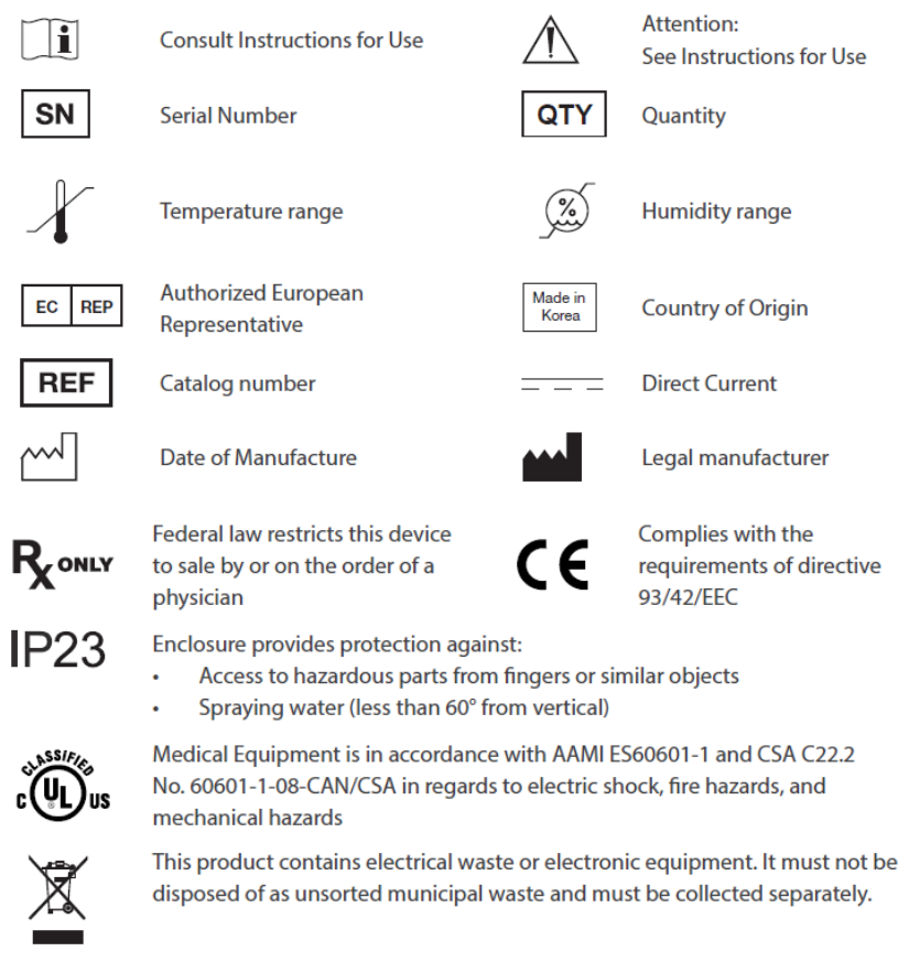
Symbols and Definitions
The following symbols appear on the product, its labeling, or the product packaging. Each symbol carries a special
definition, as defined below: