BCM Communication MOR600 Mobile Router User Manual
BCM Communication Co., Ltd. Mobile Router
User manual
FEDERAL COMMUNICATIONS COMMISSION
This device complies with Part 15 of the FCC Rules.Operation is subject to the following two
conditions:(1) this device may not cause harmful interference, and (2) this device must
accept any interference received, including interference that may cause undesired
operation.
NOTE
This equipment has been tested and found to comply with the limits for a Class B digital device,
pursuant to Part 15 of the FCC Rules. These limits are designed to provide reasonable protection
against harmful interference in a residential installation. This equipment generates, uses and can
radiated radio frequency energy and, if not installed and used in accordance with the
instructions, may cause harmful interference to radio communications. However, there is no
guarantee that interference will not occur in a particular installation If this equipment does cause
harmful interference to radio or television reception, which can be determined by turning the
equipment off and on, the user is encouraged to try to correct the interference by one or more of
the following measures:
-Reorient or relocate the receiving antenna.
-Increase the separation between the equipment and receiver.
-Connect the equipment into an outlet on a circuit different from that to which the receiver is
connected.
-Consult the dealer or an experienced radio/TV technician for help.
Changes or modifications not expressly approved by the party responsible for compliance could
void the user‘s authority to operate the equipment.
The antenna(s) used for this transmitter must not be co-located or operating in conjunction with
any other antenna or transmitter
This equipment complies with FCC RF radiation exposure limits ser forth for an uncontrolled environment.
This equipment should be installed and operated with a minimum distance of 20 centimeters between the
radiator and your body.
1 V 0.5
MOR600 Mobile Router Quick Installation Guide
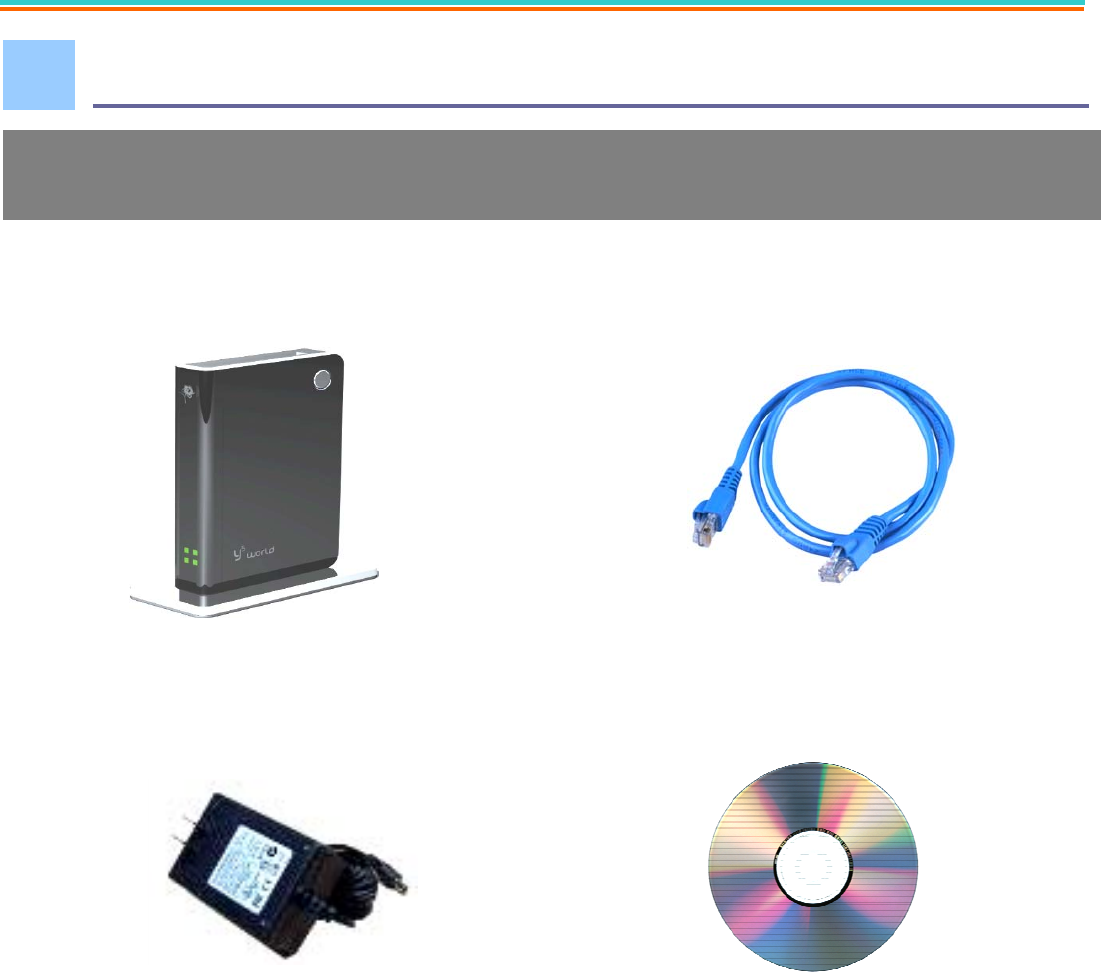
Verify Package Contents
• MOR600 Router • Ethernet Cable
• DC 5V/2A Power Adapter • User Guide on CD-ROM
• Quick Installation Guide
1.
The MOR600 Mobile Router package should contain the items Listed below . I
f
any of the items are missing please contact your Reseller .
2 V 0.5
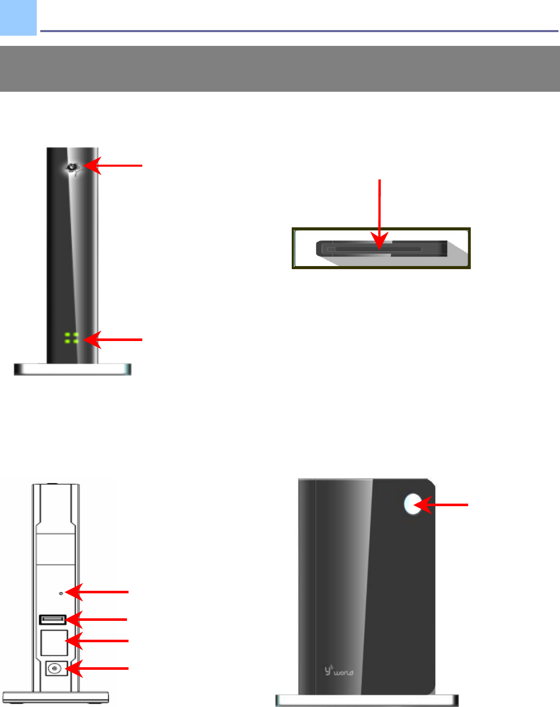
Connections and LEDS
Power
LED
Status
LED
PC Card Slot
WiFi Secure
Set Button
The following figures show the various connectors and status LED indicators
on the MOR600 Mobile Router .
2.
3 V 0.5
Default Button
Ethernet LAN Port
Power Jack
USB Port (Optional)
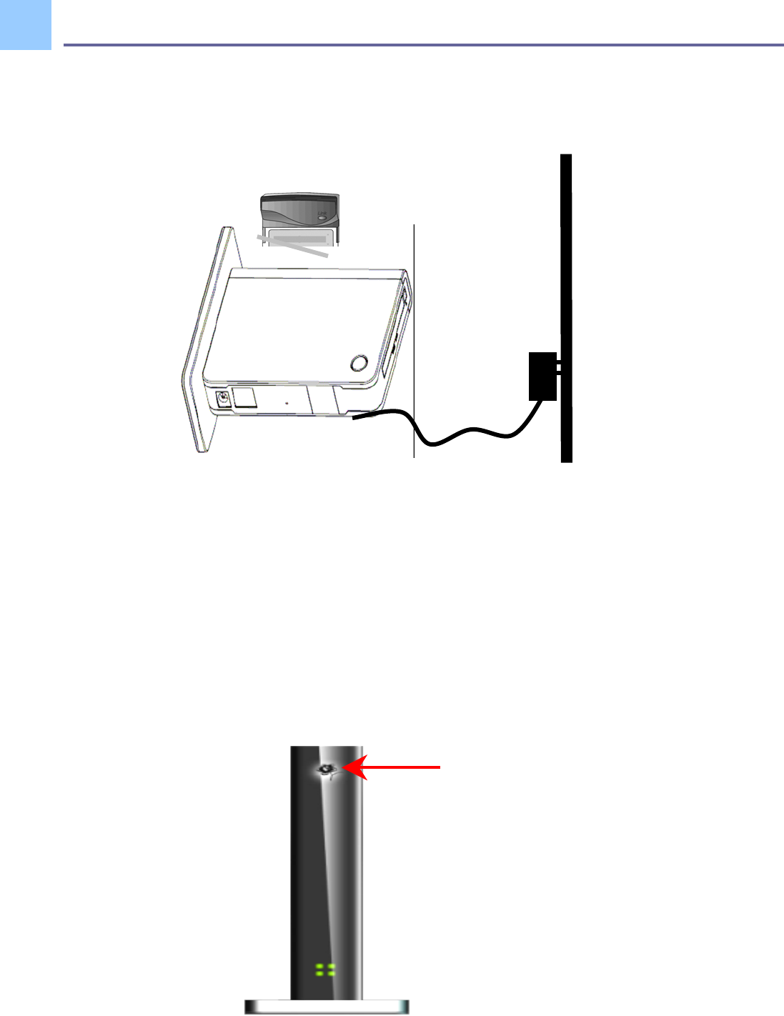
Getting Start
Step 1 Plug in power adapter
When connect the power adapter to back panel power Jack 。The power LED Will Turn ON
to indicate power has been applied.
Powe
r
LED
3.
4 V 0.5
STEP 2:Check Status LED
When Power ON the MOR600, the status LED Will Flash ON and OFF One by one as
MOR600 Performs initialization and Internet connection process。MOR600 Will Auto
Configured properly for your Internet Service Account。It Will take a few minutes。
When Complete, the status LED Will illuminate Green。Please refer the below Status
LED Activity table for each State。
Congratulation! You have Connected With Wireless Internet
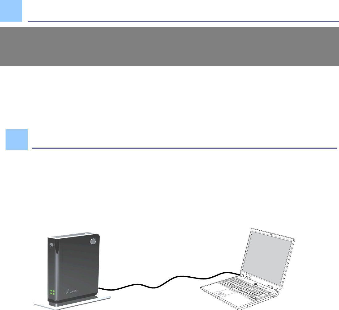
Advance Setting in Web page
STEP 1:Connect your PC/Notebook to MOR600
LAN
MOR600 Will Auto Configuration and enable the Wireless LAN. If you have to
any problem or need more advance feature Setting . Please refer the step 5 for
more detail.
4.
5.
5 V 0.5
6 V 0.5
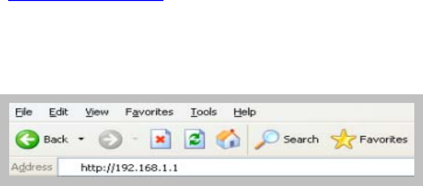
STEP 2:Open your browser Such as IE or Netscape and type Press
Enter http://192.168.1.1 in address bar.
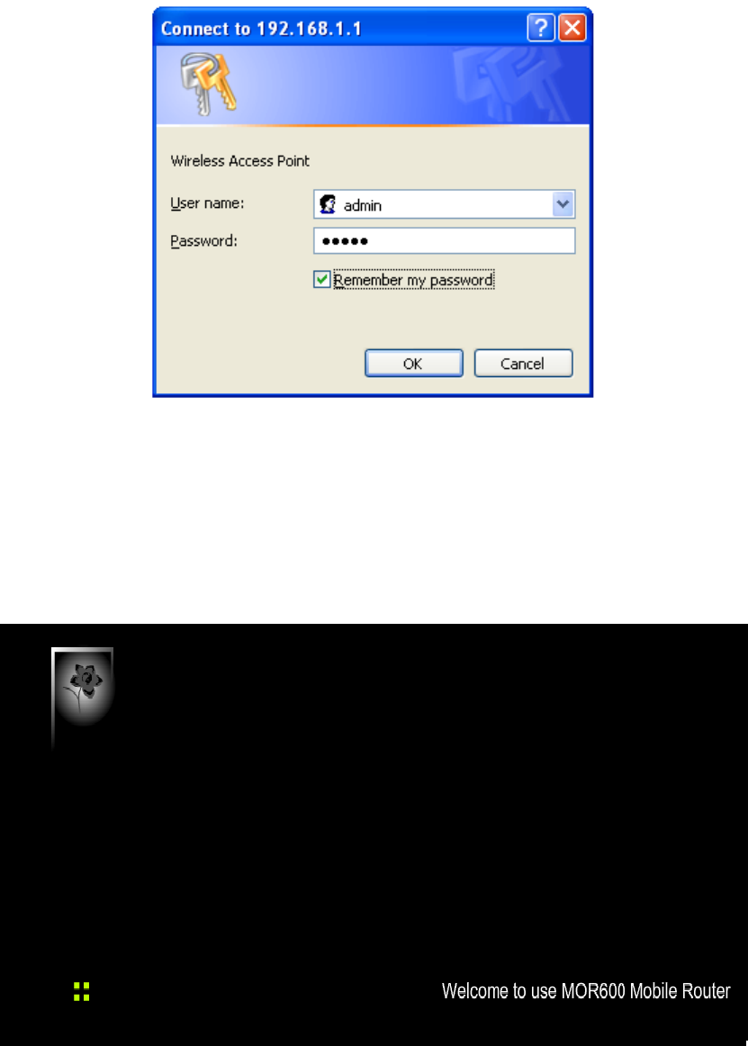
STEP 3:Login Mobile Router
•
Enter your user name in
the
User
name
box. The
default user name is
admin
.
•
Enter your passwor
d in
the
Passwor
d
box. The
default passwor
d is
admin
.
•
Click
OK
.
7 V 0.5
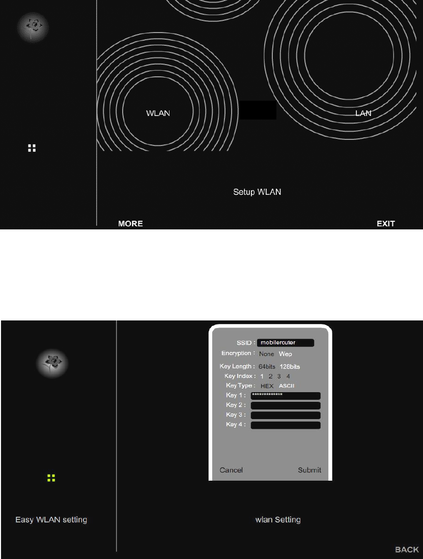
STEP 4:Once logged in the following screen is displayed
STEP 5:Click WLAN for wireless network setting
8 V 0.5
10 V 0.5
STEP 7:Click LAN for Local Network setting
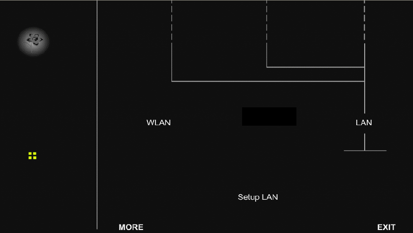
SSID :
Enter your SSID name in the field provided. SSID names Can contain
up to 32 ASCLL characters.
Encryption :You may select from two levels of encryption to secure your wireless
Network:None or WEP .
Key Length :Two levels of wireless encryption are available:64 bits and 128 bits.
Key Type :Two type of WEP Key:Hex or ASCII . choose the proper one for key
setting .
Key1~Key4 :
You can enter the WEP key by manually and choose Key1~Key4 for
enable.
11 V 0.5
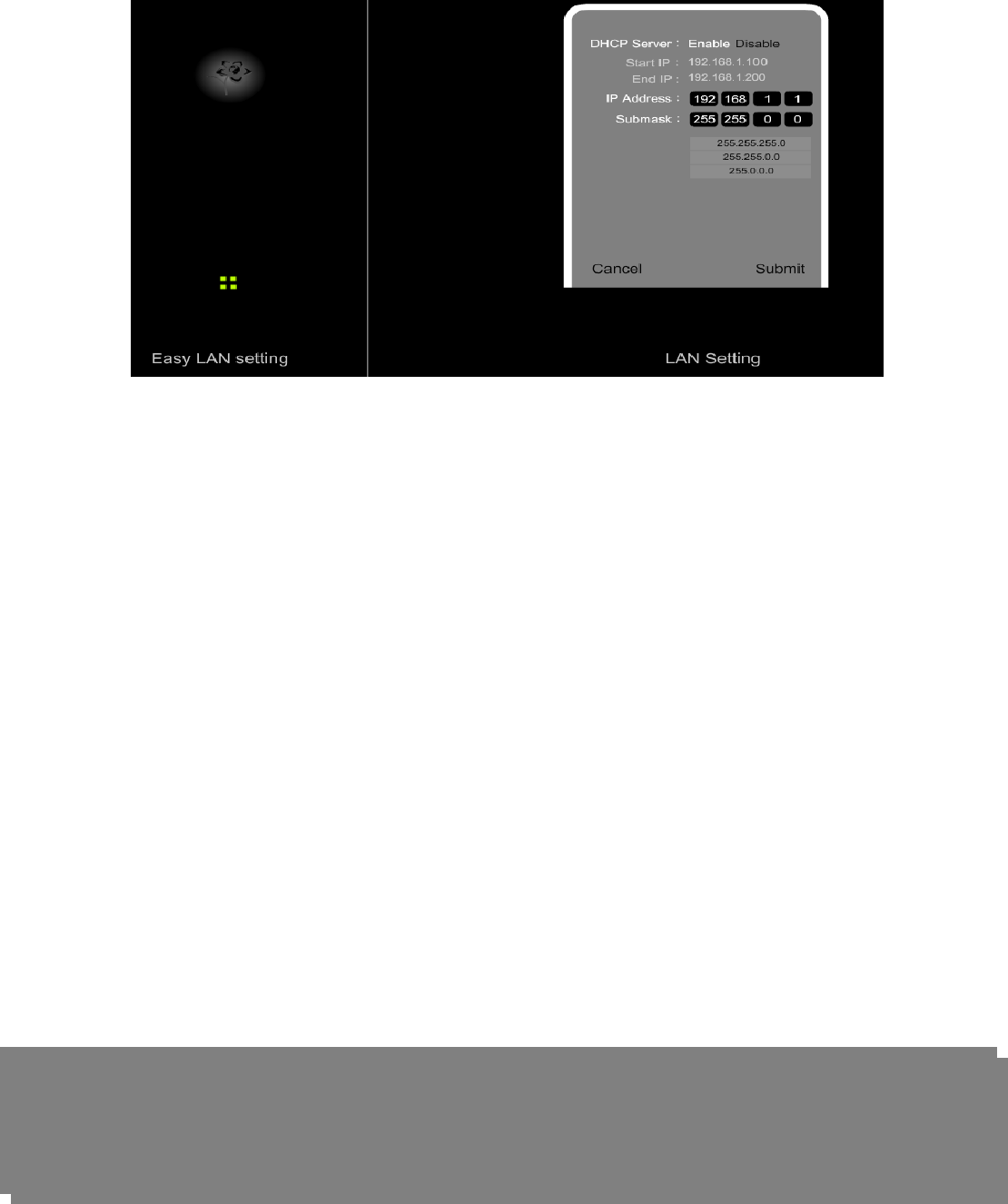
DHCP Server :
This setting is used to configure MOR600’s Dynamic Host Configuration
Protocol (DHCP)server function. MOR600 can be used as a DHCP
server for the internal LAN network . The DHCP server automatically
assigns an IP address to each computer in the LAN network . If you
choose to enable MOR600 s DHCP server option, you must configure all
of PCs in the LAN network to connect to this DHCP server (MOR600),
and make sure there is no other DHCP server on your network .
Start IP Address:Enter the values for start IP address. The default start IP address is
192.168.1.100.
End IP address :
Enter the values for end IP address. The default end IP address is
192.168.1.200.
IP Address :The IP Address of the LAN . The default IP address is 192.168.1.1
Net mask :
The subnet mask of the LAN
Note: When the DHCP server IP address range is set , it must be assured that
there is no other device in the network to use the IP address located in this
address range , such as printer server , file server , etc . Otherwise there is
risk for address conflict .
12 V 0.5