BEA orporated 10RD900 Receiver in the 902-928MHz band User Manual 75 5786 01 900 MHz TX RX 20140723 indd
BEA Incorporated Receiver in the 902-928MHz band 75 5786 01 900 MHz TX RX 20140723 indd
Users Manual
75.5786.01 900 MHz TX-RX 20140723 Page 1 of 4
900 MHZ TRANSMITTERS & RECEIVER
Digital transmitters and receiver with
frequency hopping and sequencing and
extended hold functionality
(US version)
ENGLISH
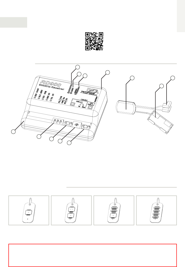
1. receiver (10RD900)
2. antenna wire
3. blue activation LED
4. red learn LED
5. tri-color signal strength LED
6. DIP switches
7. no-delay learn button
8. delay learn button
9. delay learn POT
10. transmitter (10TD900PB)
11. push plate connectors
12. battery cradle
2
3
4 5
10
11
12
HAND HELD TRANSMITTERS
DESCRIPTION
10TD900HH410TD900HH310TD900HH2
IMPORTANT:
This product is NOT intended for use directly with Magnetic Locks or Electric Strikes.
Contact BEA Technical Support for further information.
1
6
7
8 9
10TD900HH410TD900HH310TD900HH1
Page 2 of 4 75.5786.01 900 MHz TX-RX 20140723
• The device should not be used for purposes other than its intended use. All other uses cannot be guaranteed by
the manufacturer of the sensor.
• The installer of the door system is responsible for carrying out a risk assessment and installing the sensor and the
door system in compliance with applicable national and international regulations and standards on door safety.
• The manufacturer of the sensor cannot be held responsible for incorrect installations or inappropriate adjustments
of the sensor.
PRECAUTIONS
qShut off all power going to header before attempting any wiring procedures.
qMaintain a clean & safe environment when working in public areas.
qConstantly be aware of pedestrian traffic around the door area.
qAlways stop pedestrian traffic through the doorway when performing tests that may result in unexpected reactions
by the door.
qESD (electrostatic discharge): Circuit boards are vulnerable to damage by electrostatic discharge. Before handling
any board ensure you dissipate your body’s ESD charge.
qAlways check placement of all wiring before powering up to ensure that moving door parts will not catch any wires
and cause damage to equipment.
qEnsure compliance with all applicable safety standards (i.e. ANSI A156.10) upon completion of installation.
qDO NOT attempt any internal repair of the components. All repairs and/or component replacements must be
performed by BEA, Inc. Unauthorized disassembly or repair:
1. May jeopardize personal safety and may expose one to the risk of electrical shock.
2. May adversely affect the safe and reliable performance of the product resulting in a voided warranty.
Hand Held Configuration
INSTALLATION
Wiring
TERMINAL: 1 2 3 4 5
LABEL: 12-24 V 12-24 V COM NO NC
WIRE COLOR: red black white green yellow
SIGNAL: + voltage - voltage common normally open normally closed
DESCRIPTION: power relay contacts
SETUP
DIP Switches
DIP STATUS FUNCTION DESCRIPTION
1
PUL Pulse Relay pressing transmitter activates and holds relay according to DIP 2 and 3
TOG Toggle
Relay pressing transmitter once activates and holds relay indefinitely
pressing transmitter again deactivates relay immediately (no hold)
2
(PUL only)
0.5s 0.5 second
hold time relay remains active for 0.5 seconds after transmitter is...
pressed [STD] released [EH]
10s 10 second
hold time relay remains active for 10 seconds after transmitter is...
pressed [STD] released [EH]
3
STD standard
hold
relay acts according to DIP 1 and 2
(does not matter if transmitter is pressed/released or pressed/held)
EH extended
hold
relay remains active as long as transmitter is pressed and held
once released, relay acts according to DIP 1 and 2
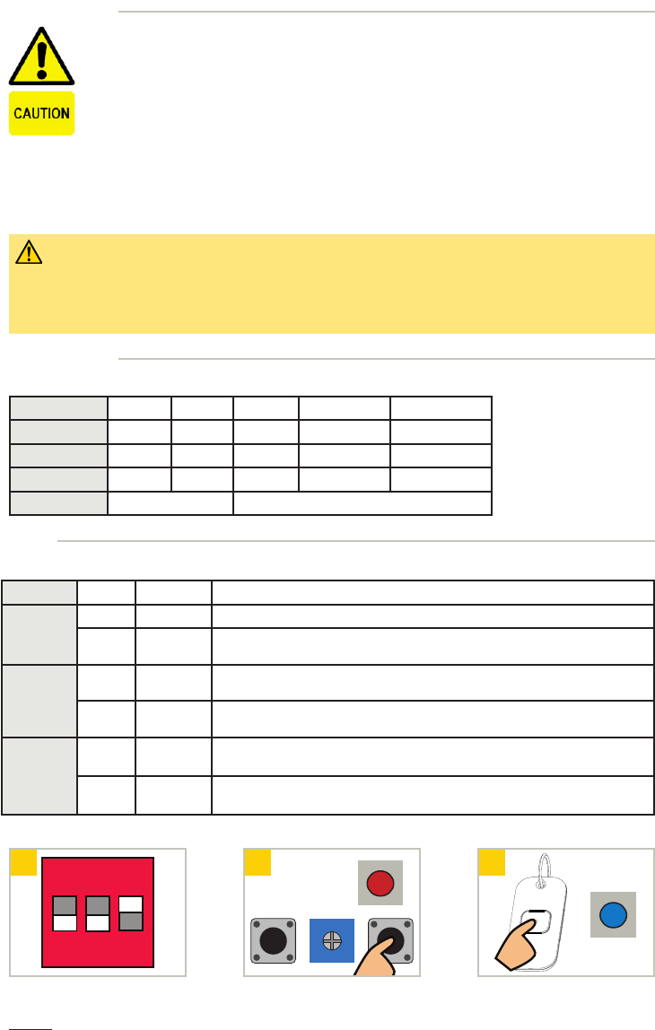
1 2 3
ON
1 2 3
Set DIP switches as desired. Press transmitter twice (blue LED
on receiver will illuminate).
Press and release desired learn button
(red LED on receiver will illuminate)1.
NOTES: 1If Learn w/ Delay button is used, adjust potentiometer (1 s to 30 s).
75.5786.01 900 MHz TX-RX 20140723 Page 3 of 4
All Transmitters
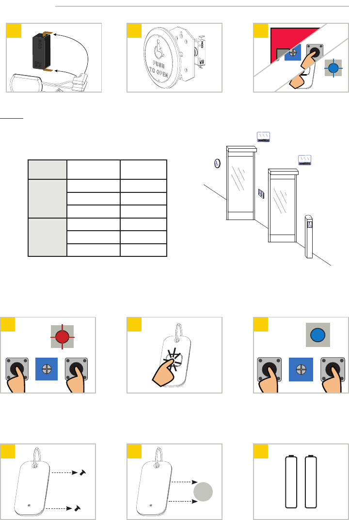
Removing Transmitters
Single Transmitter
1
x2
2 1
Press BOTH learn buttons until
red LED flashes once (~2 s). Press BOTH learn buttons until
blue LED illuminates (~10 s).
Press transmiter TWICE within
10 seconds.
SETUP (cont.)
Push Plate Configuration
21
1 2 3
ON
3
Connect transmitter1 to push plate
(NO & COM) and insert into box. Follow steps 1-3 in Hand Held
Configuration
Install push plate.
NOTES: 1: 10TD900PB required for push plates
Vestibule Configuration
RECEIVER TRANSMITTER LEARN1
Outer
outer (1) No Delay
inner (2) Delay
vestibule (4) No Delay
Inner
outer (1) Delay
inner (2) No Delay
vestibule (3) No Delay
Battery Replacement
Push Plate (TD900PB)Handheld (TD900HHx)
1
3 V
2
AAA Battery
AAA Battery
1
Remove back screws and
disassemble. Replace 2 AAA batteries
observing polarity.
Replace 3 volt (CR2032) battery
observing polarity and reassemble.
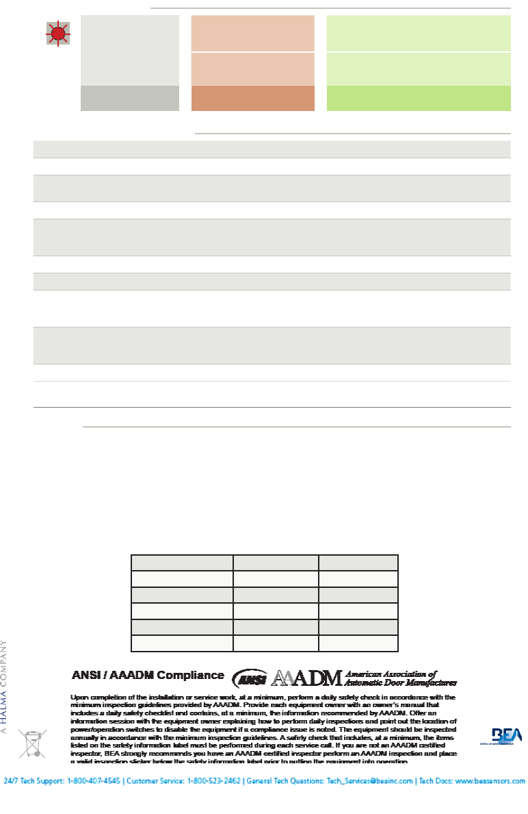
Low Battery Indicator - After transmitter button is pressed, low battery is indicated by three (3) transmiter LED blinks.
OUTER
RECEIVER
1
2
3
INNER
RECEIVER
4
Signal Strength Indicator - Pressing and holding transmitter button for 3 seconds activates signal strength tri-color LED
on receiver. Green = strong signal, Yellow = medium signal, Red = weak signal.
For vestibule applications, program each receiver to the appropriate
transmitters according to the chart below and the picture to the right.
NOTE: All transmitters must ONLY be powered with provided batteries or equivalent.
Page 4 of 4 75.5786.01 900 MHz TX-RX 20140723
PLEASE KEEP FOR FURTHER USE – DESIGNED FOR COLOR PRINTING
©BEA | Original Instructions | 75.5786.01 900 MHz TX-RX 20140723
TECHNICAL SPECIFICATIONS
Frequency: 908-918 MHz (frequency hopping)
Emitted radio power: -25 dBm (TX)
Power consumption: 30mA (TX)
40mA (RX)
Supply voltage: 12-24 VAC/DC
Contact rating: 1.0 A @ 30 VDC
0.5 A @ 125 VAC
0.3 A @ 60 VDC
Temperature range: 14°F to 131°F (-10°C to 55°C)
Programmable units per receiver: 74
LEDs: red (receiver learn)
blue (relay activation)
tri-color (signal strength)
Dimensions: 2.5” (W) x 2.0” (D) x 0.75” (H) [RD900]
2.75” (W) x 1.38” (D) x 0.56” (H) [TD900HHx]
1.75” (W) x 1.0” (D) x 0.3” (H) [TD900PB]
Certification: FCC, IC
Specifications are subject to changes without prior notice.
All values measured in specific conditions.
red LED on receiver
flickering; unable to
program
stuck push plate disconnect push plates to determine which is
stuck (LED should go out)
faulty transmitter
if LED does not go out, remove transmitter
batteries to determine which is faulty, replace
transmitter
weak signal receiver antenna positioned
poorly position antenna outside of door header
TROUBLESHOOTING
FCC / IC
“This device complies with Part 15 of the FCC Rules. Operation is subject to the following two conditions: (1) this device may not cause harmful interference, and
(2) this device must accept any interference received, including interference that may cause undesired operation.”
Changes or modifications not expressly approved by BEA Incorporated could void the user’s authority to operate the equipment.
Note: This equipment has been tested and found to comply with the limits for a Class A digital device, pursuant to part 15 of the FCC Rules. These limits are
designed to provide reasonable protection against harmful interference when the equipment is operated in a commercial environment. This equipment generates,
uses, and can radiate radio frequency energy and, if not installed and used in accordance with the instruction manual, may cause harmful interference to radio
communications. Operation of this equipment in a residential area is likely to cause harmful interference in which case the user will be required to correct the
interference at his own expense.
This device complies with Industry Canada licence-exempt RSS standard(s). Operation is subject to the following two conditions: (1) this device may not cause
interference, and (2) this device must accept any interference, including interference that may cause undesired operation of the device.
Le présent appareil est conforme aux CNR d’Industrie Canada applicables aux appareils radio exempts de licence. L’exploitation est autorisée aux deux conditions
suivantes : (1) l’appareil ne doit pas produire de brouillage, et (2) l’utilisateur de l’appareil doit accepter tout brouillage radioélectrique subi, même si le brouillage
est susceptible d’en compromettre le fonctionnement.
FCC ID: 2ABWS-10RD900 IC: 4680A-10RD900 MODEL: 10RD900
FCC ID: 2ABWS-10TD900PB IC: 4680A-10TD900PB MODEL: 10TD900PB
FCC ID: 2ABWS-10TD900HH4 IC: 4680A-10TD900HH4 MODEL: 10TD900HH1
FCC ID: 2ABWS-10TD900HH4 IC: 4680A-10TD900HH4 MODEL: 10TD900HH2
FCC ID: 2ABWS-10TD900HH4 IC: 4680A-10TD900HH4 MODEL: 10TD900HH3
FCC ID: 2ABWS-10TD900HH4 IC: 4680A-10TD900HH4 MODEL: 10TD900HH4