BEA 75.0084.06 SUPERSCAN SMR 20150618x User Guide Super Scan 20150618
User Manual: BEA User Guide - SuperScan User Guide
Open the PDF directly: View PDF ![]() .
.
Page Count: 17
75.0084.06 20150618 Page 1 of 17
DESCRIPTION
TECHNICAL
SPECIFICATIONS
SUPERSCAN
USER’S GUIDE
PRESENCE SENSOR
The SuperScan (10SSI, 10SSII, 10SSIII) detector is a door-mounted presence detection system that is used on automatic
pedestrian swing doors. The SuperScan can be used on an SMR or non-SMR system. Unlike other door-mounted sensing
devices, the SuperScan's unique electronic architecture allows the detection modules to be mounted near the top of the
door, out of harm's way. A rotating cam is used for the range adjustment of the detection zone. Width patterns may be
altered by adding slave modules to the master module. These slave modules are simply added by inserting them into the
aluminum extrusion, then connecting them with the attached flat ribbon cable to the next module without interrupting other
modules in the same extrusion. Once installed, the detection zone (in addition to being adjustable for distance) can be
angled independently from the other modules.
Each SuperScan module consists of two optics, a transmitter (TX) and a receiver (RX), and functions independently of the
other modules. The transmitter emits an extremely precise beam, which measures approximately 4" in diameter at a
distance of 8'. The receiver, in turn, receives the infrared beam reflected off of the floor. This transmission and reception
forms a detection triangle, which is the basic premise of detection (called triangulation). Should this angle be interrupted,
detection will occur. Detection is NOT based upon the intensity of the beam, and in principle will not be affected by the color
or background of the object that interrupts the angle.
• Shut off all power going to the header before attempting any wiring procedures.
• Maintain a clean & safe environment when working in public areas.
• Constantly be aware of pedestrian traffic around the door area.
• Always stop pedestrian traffic through the doorway when performing tests that may result in unexpected
reactions by the door.
• Always check placement of all wiring and components before powering up to ensure that moving door parts
will not catch any wires and cause damage to equipment.
• Ensure compliance with all applicable safety standards (i.e. ANSI A156.10, 156.27) upon completion of
installation.
DESCRIPTION
SPECIFICATION
Power Supply
12 to 24 VAC ± 10% / 12 to 24 VDC + 10%
Current Consumption:
Master: On = 60 mA max. / Master: Off = 30 mA max.
Slave: On = 40 mA. Max. / Slave: Off = 30 mA max.
Master: Off = 30 mA max.
Slave: On = 40 mA. max
Slave: Off = 30 mA max.
Input Inhibit
12 to 24 VAC ± 10%: / 12 to 24 VDC + 10% / Inhibited when voltage is applied
SMR Input Data
12-18 VDC: Inhibited when voltage is applied
Output Interface; relay
Relay; max. contact rating is 1A @ 30v ( resistive)
Detection Range
0' to 8'
Distance Adjustment
2’ to 8’ / Rotating cam with linear adjustment
Max. Mounting Height
8’
Detection Time
< 50 ms
Detection Signal Duration
Infinite Presence Detection
Output Hold Time
Potentiometer Range: 0.1 to 4.5 seconds.
LED Indications
Master: Red LED = Detection
Green LED = Active Output
Slave: Red LED = Detection
Operating Temperature
Range
-30° F to 140° F
PCB Dimensions
Master: 10.91" x 1.5"
Slave: 8.75" x 1.5"
Connection to Door
Controller
8 Position Screw Terminal on Master PCB
Connection: Master to
Slave
Flat Ribbon Cable With Connectors and Key Lock
Max. Number of Slaves
Standard = 9 / With Monitoring = 8 max.
Functions Selection
Detection Mode - NO or NC
Normal Mode or Background Analysis Mode
SAFETY
PRECAUTIONS
!
CAUTION
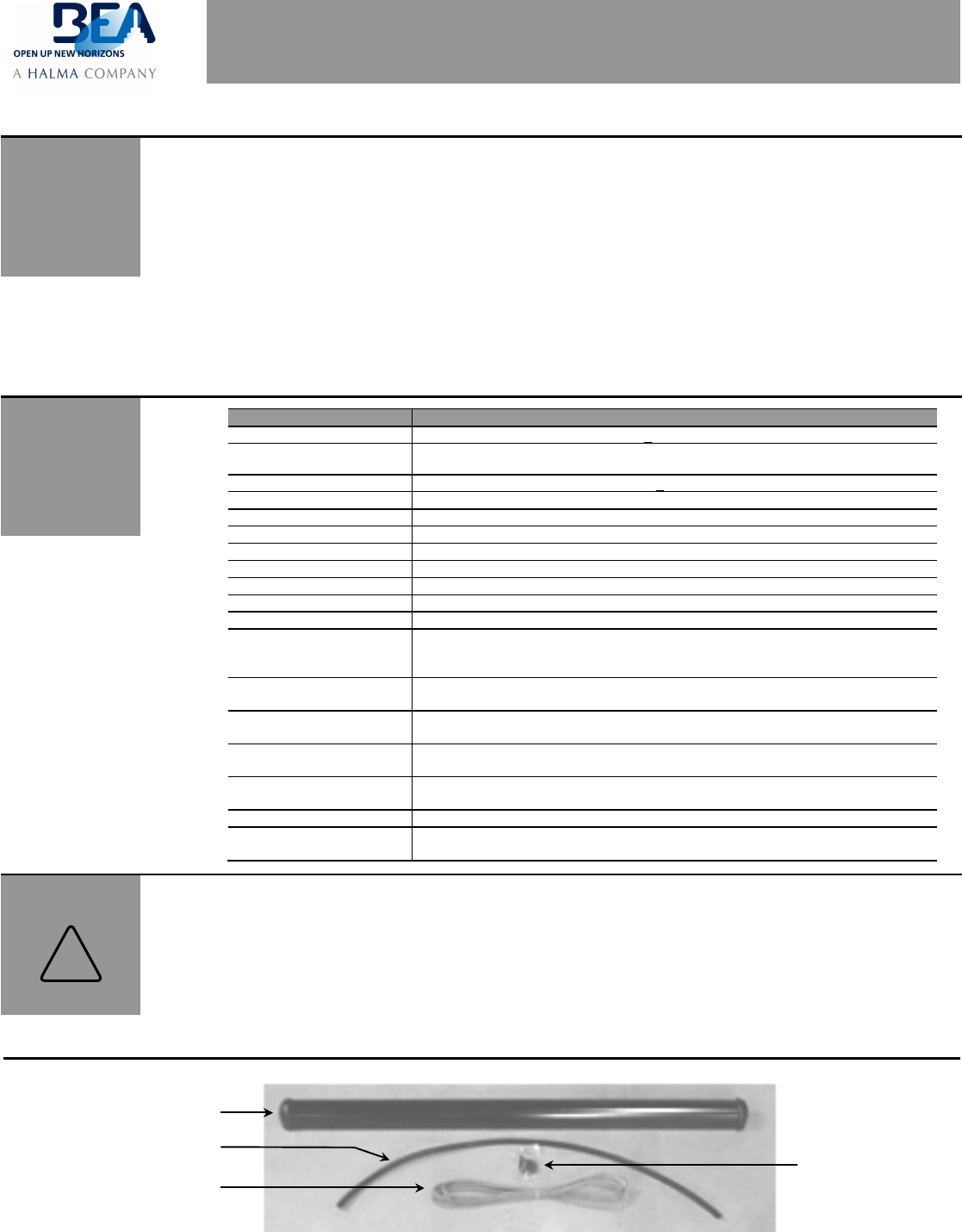
SuperScan Assembly
Wire Transfer Sheath
8-Wire Cable
Jamb Hole Cover
75.0084.06 20150618 Page 2 of 17
MECHANICAL
INSTALLATION-
PREPARING AND
MOUNTING THE
SENSOR
COMPONENT ID
CAUTION: REMOVE THE MASTER AND ALL SLAVE CIRCUIT BOARDS FROM THE ALUMINUM
EXTRUSION BEFORE PERFORMING ANY DRILLING. WHEN COMPLETE, ENSURE
THAT ALL METAL SHAVINGS ARE CLEANED FROM THE EXTRUSION BEFORE
RE-INSERTING THE CIRCUIT BOARDS.
INSTALLATION
TIPS
! The sensor must be
firmly fastened to
prevent vibration.
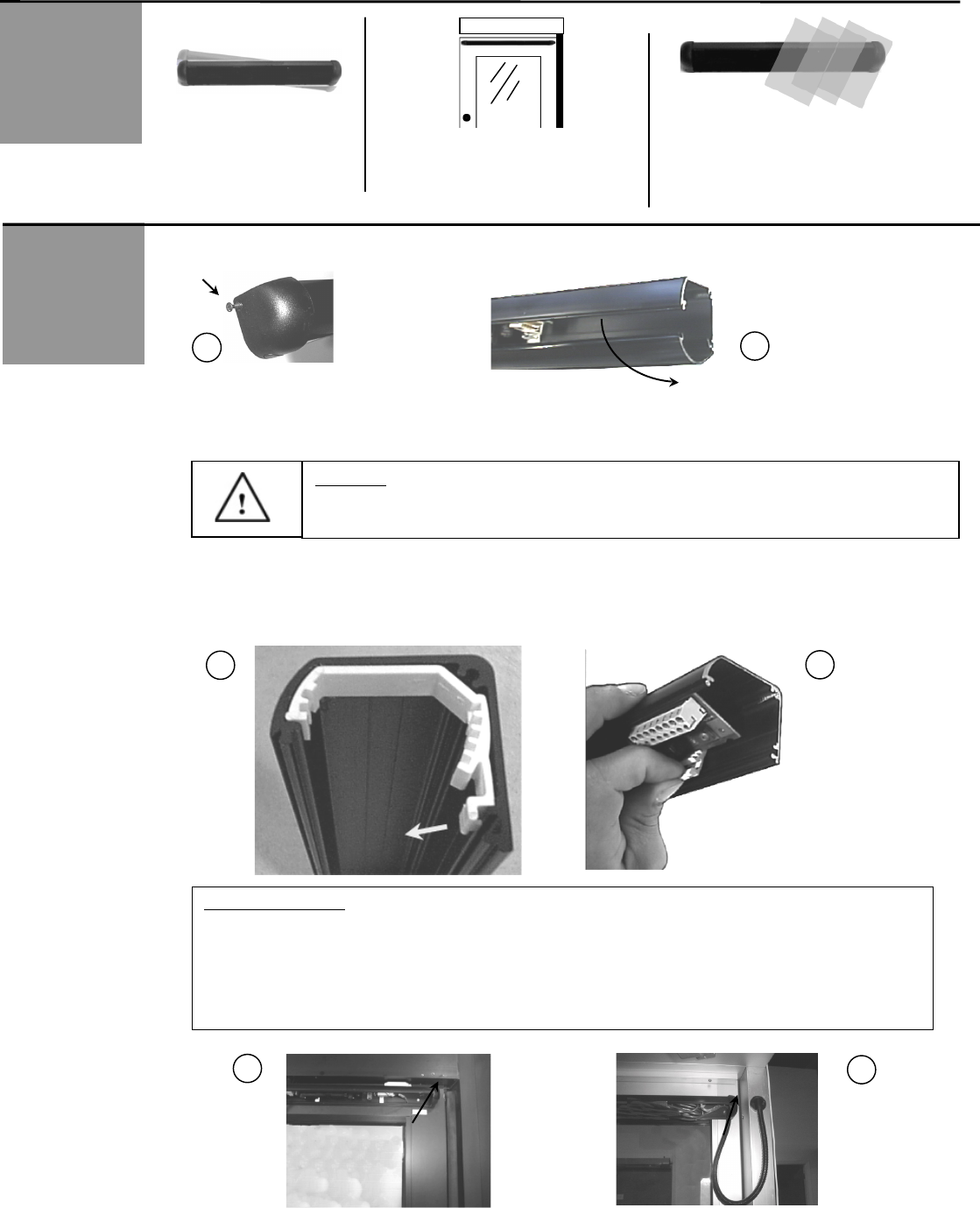
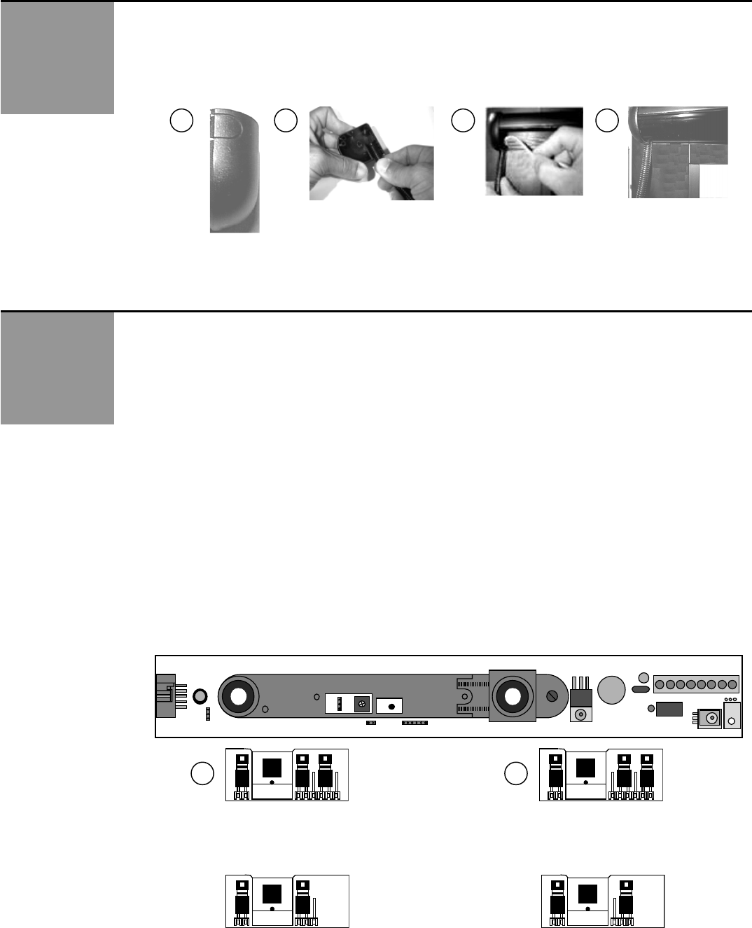
1. Remove the screw that secures the end cap to the SuperScan extrusion (as shown in Picture 1 below).
2. Remove the plastic lens by pulling the lens out from the top of the extrusion (as shown in Picture 2 above). Do not use a
screwdriver to pry the lens, as cracking may occur.
3. Picture #3 below shows the angle adjustment clip in its proper position within the extrusion (PCB’s are removed, and clip
is shown at end of extrusion for clarity only). To remove the clip, simply pull the tab out away and downward from the
extrusion, then rotate the module out from extrusion as shown in picture #4. To re-install, simply reverse the procedure -
the PCB must first be installed into the adjustment clip, then installed into the aluminum extrusion.
! Sensor must be in a location
that does not interfere with door
hardware (finger guards, lock
rods, etc.).
! The sensor must not
have any unwanted
objects likely to move or
vibrate in its path.
IMPORTANT NOTE: The end of the extrusion that is towards the pivot end of a center hung door, should be in
far enough from the edge of the door, as shown in picture #5, to prevent the end cap of the
SuperScan from rubbing against the finger guard during door movement. Pay particular
attention on the safety side of the door. Hinge hung doors will not require as much
clearance between the end of the SuperScan and hinge-side jamb as shown in picture #6
below. At the leading edge of the door, the edge of the SuperScan, including the end cap,
should be as close as possible to the leading edge of the door, without creating
mechanical interference with the door jamb or with an adjacent door (pairs).
1
2
3
4
5
6
75.0084.06 20150618 Page 3 of 17
MECHANICAL
INSTALLATION-
PREPARING AND
MOUNTING THE
SENSOR – Cont.
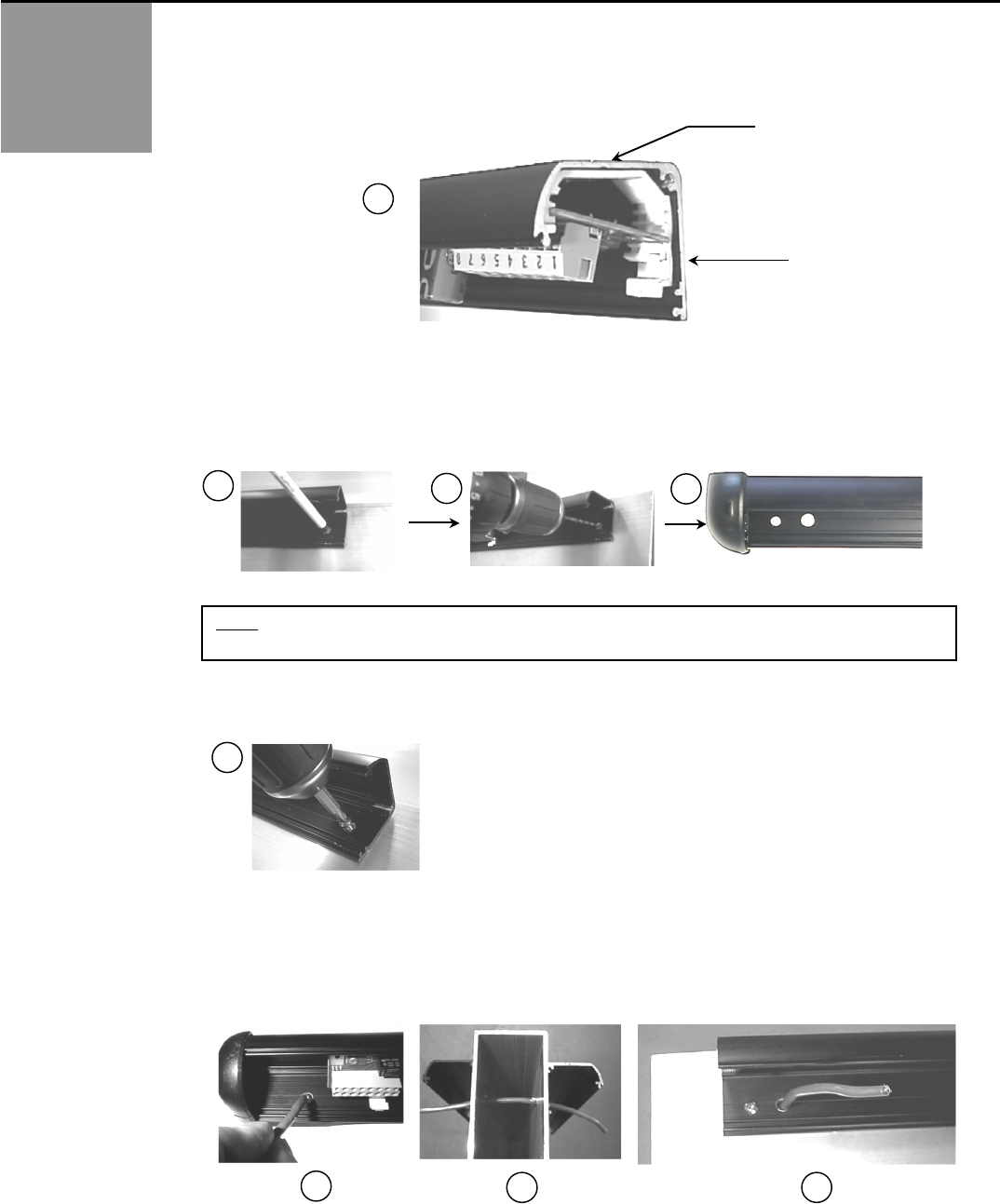
4. Hold the SuperScan extrusion up to the top of the door. Insure that the extrusion is oriented correctly as shown
below.
5. Mark and drill the extrusion (in the approximate locations as shown below) where the mounting holes (one at each
end) should be located. Also, be sure to mark and drill the proper end for an additional hole to be used for wire
passage. Wire passage hole should be approximately ¼” diameter. Screw mount holes only serve as a pilot hole for
ease of installing the self-drilling screws that are provided.
6. Hold the SuperScan back up to the door at the pre-drilled location and attach the unit to the door with the 2 screws
provided. Insure that the SuperScan extrusion is tight against the door.
7. If SuperScans are to be mounted on both sides of the door, a wire passage hole will be required through the door to
go from the approach side to the safety side, as shown below. Again, be sure not to drill through any through-bolts
or braces within the door. A cutaway view below (Picture 13) shows wire passage through the door. Picture 12 and
14 shows an approximate location for the wire passage hole. The extension wire going between the terminal blocks
should be approximately 18” long and can then be cut back if needed.
Back Side
Top Side
NOTE: Take care to avoid screw holes near the seams of the door, where it may be difficult to drill and install
a screw, and possibly damage the inside structural braces of the door.
7
8
9
10
11
12
13
14
75.0084.06 20150618 Page 4 of 17
ELECTRICAL
INSTALLATION-
CABLING &
CONNECTIONS
MECHANICAL
INSTALLATION-
PREPARING AND
MOUNTING THE
SENSOR – Cont.
8. Next, a wire passage hole will be required in the door header (Picture 15) and also in the jamb tube (Picture 16) at
approximately the same height as the SuperScan. The wire transfer hole in the jamb should be at the secure side of
the door. Normally this would be the interior side. Feed the wire through the jamb tube up to the header. Insure that
enough wire is left out to reach the SuperScan terminal block.
9. Once all cabling is in place, the plastic sheath must be installed over the wire coming out of the jamb tube. This
must be done before making final connection to the terminal block. The sheath may have to be cut to fit the
application. Once the wire is fed though, the plastic cap may be installed on the jamb, over the transfer hole.
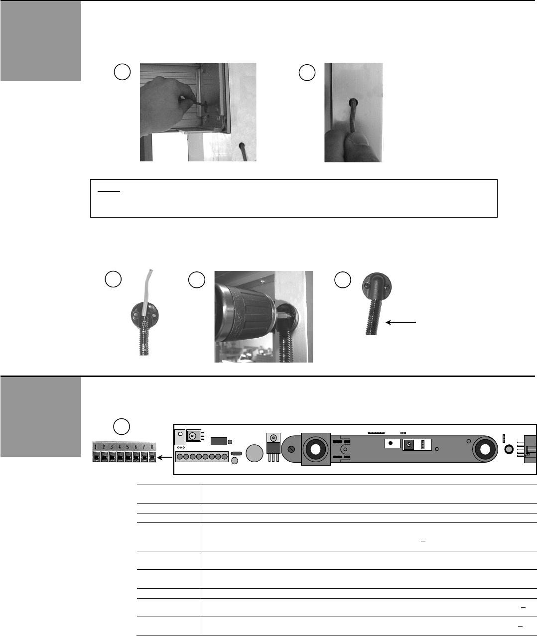
1. With cabling in place, wiring at the terminal connector on the SuperScan master module (picture 20) may be
completed. Wiring will vary according to the application. Available positions on the connector are shown below:
SuperScan
Terminal
Explanation of Wiring Connections
1
Test data - used with SMR systems only.
2
Ground. Negative terminal if Input inhibition is used.
3
Input inhibition: All detection is ignored. Infrared emission is stopped.
Inhibition occurs when 12 to 24 VAC ± 10% or 12 to 24 VDC + 10% is applied between
terminal 3 and terminal 2.
4 (NO)
JP2 factory default will close the relay contact on terminal 4 when the SuperScan is
energized and not in detection. Loss of power results in a N.O. contact
5 (NC)
JP2 factory default will open the relay contact on terminal 5 when the SuperScan is
energized and not in detection. Loss of power will result in a N.C. contact.
6 (COM)
Common contact for relay.
7 (-)
This terminal is used for power input. A voltage of 12 to 24 VAC ± 10% or 12 to 24 VDC +
10% must be supplied.
8 (+)
This terminal is used for power input. A voltage of 12 to 24 VAC ± 10% or 12 to 24 VDC +
10% must be supplied.
NOTE: Ensure there is enough slack in cabling to allow adequate movement of the cable throughout the range
of door travel.
Plastic ribbed sheath
J2
J1 J4
J3
P1
1
15
16
17
18
19
20
75.0084.06 20150618 Page 5 of 17
ELECTRICAL
INSTALLATION-
CABLING &
CONNECTIONS
Cont.
MECHANICAL
ADJUSTMENTS -
PRIOR TO
POWER-ON
2. Once all wiring has been completed, the end caps and lens may be installed. At the SuperScan end of the cable
(picture 23), leave enough slack to allow a relaxed connection at the terminal block. Locate the Superscan end cap
that goes towards the hinged end of the door. Remove the tab at the bottom of the cap (picture 21) to allow insertion of
the plastic sheath. Insert the plastic sheath (picture 22) and install the end cap. The SuperScan lens may then be
installed to fit tight against the end cap and plastic sheath to hold it in place, as shown in picture 24. Leave the end cap
off at the opposite end until all mechanical adjustments have been completed.
* Refer to the back of this Guide for various wiring schematics.
Master & Slave Module Jumper Settings: Prior to power-on, all jumper settings on the master and slave boards should
be set according to the installation.
Jumper settings include:
! Function J1: Background Analysis (master & slave boards)
! Function J2: Relay Mode (NO / NC) (master board only)
! Function J3: SMR Mode (master & slave boards)
! Function J4: Master Only or Master & Slave Configuration (master & slave boards)
1. Jumper J1, Background Analysis, is a 6-pin (older models) OR 3-pin (newer models) configuration located on each module,
as shown below in picture 25 - the location is the same for each. Background Analysis is the ability to analyze the
background in the area of the detection field, to help reduce chances of non-detection due to faulty environmental situations.
When ON (picture 26), Background Analysis allows constant detection in the event of one or more of the following situations:
! Module aimed too high
! Module incorrectly oriented (towards sky for example)
! Defective amplification chain
! Faulty infrared transmitter
! Not enough reflectivity off of floor surface
NOTE: Floor must have at least 5% reflectivity to allow Background Analysis to function properly.
This configuration greatly reduces the chance of allowing the modules to function less than optimally. If one of the above-
stated faults exists, the detector will remain active, thereby causing the door to stay open or to not open. This fail-safe
operation will cause the door to be inoperative in the automatic mode, since there will be a constant signal either to the
safety input or to the activation input of the door control, depending on which module is sensing detection. If an extreme IR
absorbent floor is present, set J1 to background analysis mode. The J1 function must be set on each module.
Newer Models – 3 Pin Jumper – Shown with same orientation as 6-pin jumper above
! The same logic applies as with the 6-pin: Center and left pin are for Normal Mode, center and right pin are for
Background Analysis Mode.
6-Pin
Normal Mode
(Default)
6-Pin
Background
Analysis Mode
3-Pin
Normal Mode
(Default)
3-Pin
Background
Analysis Mode
J3
J1
J1
J3
J3
J1
J3
J1
J2
J1
J4 J3
P1
1
21
21
22
23
24
25
26
75.0084.06 20150618 Page 6 of 17
MECHANICAL
ADJUSTMENTS -
PRIOR TO
POWER-ON
Cont.
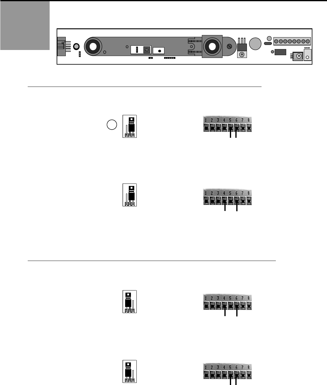
2. J2 is a two-position jumper, which enables either a passive or active relay to be selected. The SuperScan comes
factory preset with the relay in the ACTIVE MODE. J2 IS ON THE MASTER BOARD ONLY.
ACTIVE RELAY: THE RELAY IS ENERGIZED WHEN THE DETECTOR IS AT REST.
3. ACTIVE RELAY + NC & COM TERMINAL CONNECTION = CLOSED CONTACT DURING DETECTION
! Use the NC & COM terminals (5 & 6) & leave JP2 at the factory preset position.
! During detection, led indication will be green led OFF, red led ON.
! Upon power loss, the contact will be closed.
4. ACTIVE RELAY + NO & COM TERMINAL CONNECTION = OPEN CONTACT DURING DETECTION
! Use the NO & COM terminals (4 & 6) & leave JP2 at the factory preset position.
! During detection, led indication will be green led OFF, red led ON.
! Upon power loss, the contact will be open.
PASSIVE RELAY: THE RELAY IS DE-ENERGIZED WHEN THE DETECTOR IS AT REST.
5. PASSIVE RELAY + NO & COM TERMINAL CONNECTION = CLOSED CONTACT DURING DETECTION
! Use NO & COM terminals (4 & 6) & CHANGE JP2 from the factory preset position.
! During detection, led indication will be green led ON , red led ON.
! Upon power loss, the contact will be open.
6. PASSIVE RELAY + NC & COM TERMINAL CONNECTION = OPEN CONTACT DURING DETECTION
! Use the NC & COM terminals (5 & 6) & CHANGE JP2 from the factory preset position.
! During detection, led indication will be green led ON, red led ON.
! Upon power loss, the contact will be closed.
J2
View Looking
Toward P1
J2
View Looking
Toward P1
J2
View Looking
Toward P1
J2
View Looking
Toward P1
J2
J1
J4 J3
P1
1
27
75.0084.06 20150618 Page 7 of 17
MECHANICAL
ADJUSTMENTS -
PRIOR TO
POWER-ON
Cont.
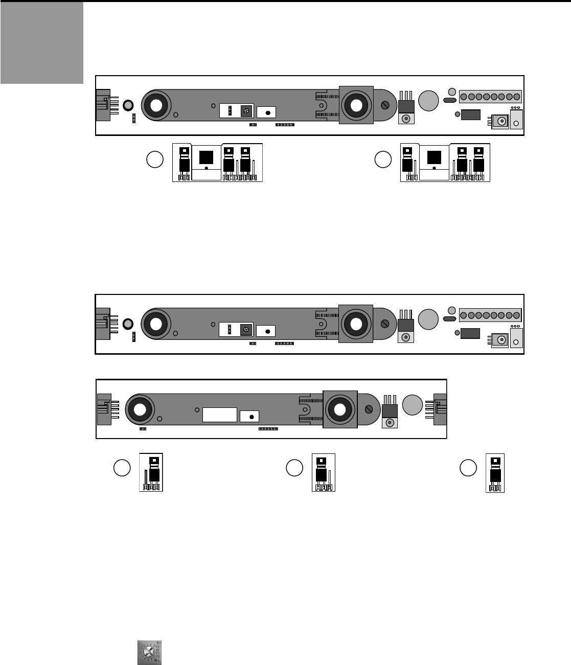
7. Jumper J3 is to toggle the SMR mode on and off, and is located on the master module only.
! Jumper installed on both pins = SMR OFF (default setting), Picture 28.
! Jumper removed (may be stored on one pin) = SMR ON, Picture 29.
! SMR is not available on master modules without jumper J3 installed. See page 8 for module configurations.
8. Jumper J4, is found on the master module, and is also found on the slave module. On the master module, it determines
‘master only’ or ‘master and slave’ configuration for use when SMR is ON. When the jumper is installed in ‘master only’
configuration, as shown below in picture 30, it is intended for use without slave modules added to the chain and is for ‘master
only’ operation. The jumper is located at the Output end of the master module. With jumper J4 installed as shown in picture
31, the master is intended for slave modules to be added. Jumper J4 is also installed on the slave module near the output end
of the module. SMR is not available on master and slave modules without jumper J4 installed. See page 8 for module
configurations.
As Shipped From BEA, Inc., default placement of J4 jumpers is as follows:
! If a Master ONLY is shipped: Jumper will be positioned for Master Only
! If a Slave ONLY is shipped: No jumper on Slave J4 position
! If a kit is shipped (i.e. SuperScan II): Jumpers correctly placed for that configuration.
9. On the slave module, jumper J4 should be installed on the last slave module in the chain, as shown above in picture
32. All slave modules between the master and the last slave should have the jumper removed. Latest module
configurations without jumper J4 installed can simply be installed in chain with the master and slaves. See page 8 for
module configurations.
10. There is a hold-time potentiometer (P1) located on the master module. It is located between the receiver and
transmitter. Adjustability ranges from 0.1 to 4.5 seconds. When installed, clockwise rotation increases time
delay.
J3
J1
J3
J1
SMR ‘OFF’
SMR ‘ON’
J4
View Looking Toward
Master Output
Master
Slave
View Looking Toward
Master Output
J4
J4
P1
J2
J1
J4 J3
P1
1
J2
J1
J4 J3
P1
1
J1
J4
28
29
30
31
32
75.0084.06 20150618 Page 8 of 17
MASTER / SLAVE
CONFIGURATION
AND
COMPATIBILITY
LIST
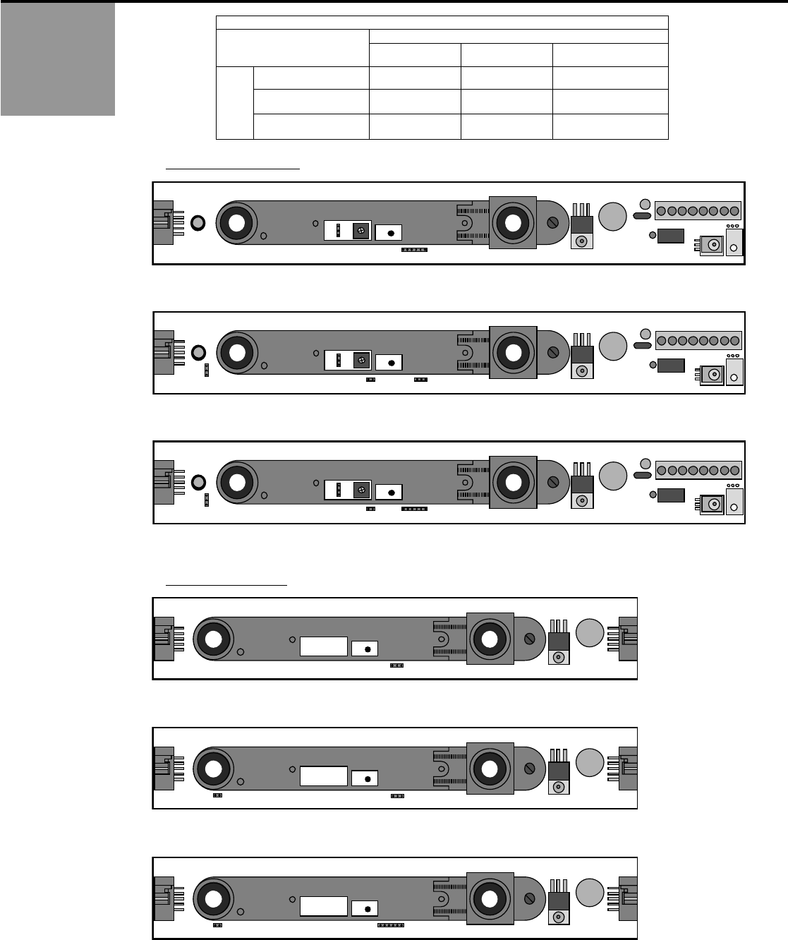
MASTER AND SLAVE MODULE COMPATIBILITY TABLE
Compatible: √
Not Compatible: X
MASTER
Config.1 SMR
Config.2 SMR
Config.3 Non SMR
SLAVE
Config.1 SMR
√
√
X
Config.2 SMR
√
√
X
Config.3 Non SMR
√
√
√
MASTER MODULES
SLAVE MODULES
Configuration 3 – Non SMR: Jumpers: J1 ‘6 Pin’ and J2 (Latest Master Module)
Configuration 2 - SMR: Jumpers: J1 ‘3 Pin’, J2, J3 and J4 (Subsequent Master Module)
Configuration 1 - SMR: Jumpers: J1 ‘6 Pin’, J2, J3 and J4 (Earliest Master Module)
Configuration 3 – Non SMR: Jumper: J1 (Latest Slave Module)
Configuration 2 - SMR: Jumper: J1 ‘3 Pin’ and J4 (Subsequent Slave Module)
Configuration 1 - SMR: Jumper: J1 ‘6 Pin’ and J4 (Earliest Slave Module)
J2
J1
P1
1
J2
J1
J4 J3
P1
1
J2
J1
J4 J3
P1
1
J1
J1
J4
J1
J4

75.0084.06 20150618 Page 9 of 17
MECHANICAL
ADJUSTMENTS –
POSITIONING AND
ANGLING THE
MODULES
1. The positioning of the modules within the aluminum extrusion will be as shown below. The modules will always be
positioned so that the transmitter (TX) is at the leading edge of the door. Modules may be flipped around to
accommodate handing of doors.
Approach Side
Safety Side
Hinge Side
Leading Edge
Side
Slave module
Master module
Door Cord
(must be placed on interior of door)
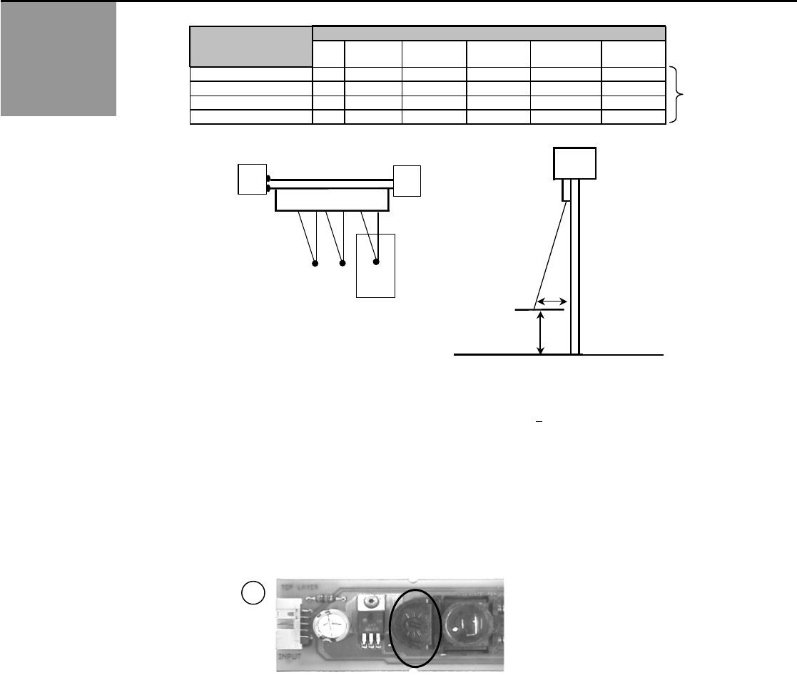
2. The angle of each module may be set independently. Use the charts below to help determine the angling. The angles
may have to be altered once the units have been powered up and walk-tested.
TX
RX
TX
RX
Master Module
Slave Module
O
U
T
P
U
T
I
N
P
U
T
Ribbon Cable
Ribbon Cable
75.0084.06 20150618 Page 10 of 17
POWER-ON
POSITIONING,
ANGLING AND
ADJSUTING THE
MODULES
SUPERSCAN
IR
Floor
Cardboard
SIDE VIEW
Dead Zone
Detection
Distance
DOOR
VIEW FROM ABOVE
SUPERSCAN
Cardboard
IR
3. The following procedures will be used to adjust each module’s detection zone upon power-on, and must be made with the
Background Analysis jumper set to ‘Normal Mode’. (see page 5)
! Power the sensors with 12 to 24 VAC ± 10% or 12 to 24 VDC + 10%. LED status should reflect what was
configured for the relay output. Refer to page 8.
! Use a white, gray, or black piece of cardboard about 8" x 11" and hold it as shown in the diagram above.
! Move the cardboard from the floor upward until it is detected. This will determine the height of the inactive
area (B distance).
! Measure the height at which the cardboard was detected.
! If this height does not fall between 12" & 16" above the floor or does not meet your requirements, an
adjustment must be made to the detection distance.
! One notch of the distance adjustment corresponds to approximately 4".
! If Zone B is too high: Turn the distance adjustment clockwise to increase the detection distance and to
decrease Zone B.
! If Zone B is too low, turn the distance adjustment counter-clockwise to decrease the detection distance.
! Per current ANSI A156.10, 156.27 the detection zone must be within 28” of the floor. Ideally, each detector
should be adjusted so that detection occurs at 12” to 16” above the floor. Less than 12” of Zone B may
result in occasional false triggering of the sensor.
! Once all sensors have been adjusted, activate the door several times and allow it to go through a full cycle
each time. Insure that no false triggering is occurring, as would be indicated by the door recycling or
stopping by itself at any point of travel.
! Ensure compliance of all applicable safety standards (i.e. ANSI A156.10, 156.27).
! Install all remaining covers, end caps, screws, etc.
INACTIVE ZONE
(B) DISTANCE
FROM FLOOR
SUPERSCAN ANGLE (C)
0°
5°
10°
15°
20°
25°
8"
0
6"
12 ½"
19 ¼"
26"
33 ¼"
12"
0
6"
12"
18"
24 ½"
31 ½"
16"
0
5 ½"
11 ¼"
16 ¾"
23 ¼"
29 ½"
20"
0
5 ¼"
10 ½"
16"
21 ½"
27 ½"
A
A
Note: Dimension “A” and “B”
are approximate.
A
B
Detection Distance Adjustment
33
75.0084.06 20150618 Page 11 of 17
TROUBLE-
SHOOTING
SMR & NON-SMR
COMPATIBILITY
ACCESSORIES
When using SMR (self-monitoring ready) and non-SMR modules in the same chain, observe the following rules:
! Mon-SMR Master modules can NOT be used with SMR Slave modules.
! All other combinations will work. However, for a system to function as SMR, all modules must be SMR
Identifying an SMR module can be accomplished by looking at the white label on the emitter side of the module. Observe the
following to identify each module:
SMR
NON-SMR
MASTER
EYETECH / MRC
EYETECH / MR
SLAVE
EYETECH / SC
EYETECH / S
For example, a Master module with the marking: EYETECH/MRC would indicate that the module is SMR.
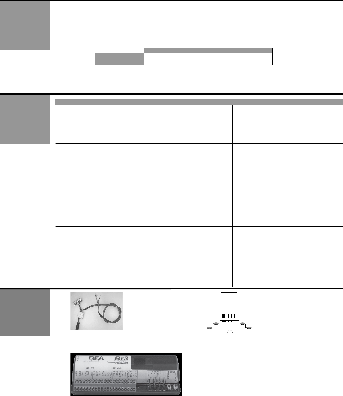
PROBLEM
POSSIBLE CAUSE
CORRECTIVE ACTION
SuperScan does not work
at all. No LED indications.
Faulty power supply
Faulty connections
Power supply must be 12 to 24 VAC ± 10% or
12 to 24 VDC + 10%.
Check for this power at terminals 7 & 8 of the
affected SuperScan module.
SuperScan output appears to
be working opposite of what is
expected.
Relay output may be configured
improperly.
Refer to page 8 for relay configurations. Be
sure to observe the LED indications on the
affected modules to help determine status.
Door stops by itself before
reaching the full open position.
Safety side SuperScan may be
seeing an adjacent wall or rail
behind the door near the open
position.
Observe the LED status on safety side of
door. Find the SuperScan module that is
falsely being triggered. Check for:
! Proper detection angle
! Detection range adjustment
SuperScan may need to be inhibited at a
specific point of door travel at the safety side
for proper operation. Refer to the terminal
connections on page 4.
Activation or safety is being
held triggered.
SuperScan detection module may
be seeing the floor or unwanted
object near door.
Reduce the detection range on the affected
module(s). Detection should occur at 12” to
16” above the floor. Refer to page 11.
Erratic detection behavior is
occurring throughout the door’s
opening and closing cycle.
Possible faulty wiring at door
transfer location.
Check each wire for continuity with as multi-
meter, at the transfer location. Move the
wires around during testing to help locate
any breaks. Replace faulty wiring as
necessary.
PN: 10SSQD
Quick Disconnect
Cable
PN: 10REL24V
Isolation Relay
PN: 10BR3
Interface module

75.0084.06 20150618 Page 12 of 17
ANSI / AAADM Compliance: American Association of Automatic Door Manufactures AAADM
Upon finishing the installation and/or service work perform at a minimum a daily safety check in accordance with the
minimum inspection guidelines provided by AAADM. Provide each owner with an owner’s manual that includes a daily
safety checklist and contains at a minimum the information recommended by AAADM. Offer a familiarization session
with the owner explaining how to do daily inspections and calling out location of cutoff switches to put equipment out
of service if a deficiency is noted. The equipment should be inspected in accordance with the minimum inspection
guidelines annually. A safety check that includes at a minimum the items listed on the safety information label must be
performed during each service call. If you are not an AAADM certified inspector BEA strongly recommends to have an
AAADM certified inspector perform an AAADM inspection and placing a valid inspection sticker below the safety
information label prior to placing the equipment into operation.
ANSI /AAADM
COMPLIANCE
COMPANY(
CONTACT(
!
75.0084.06 20150618 Page 13 of 17
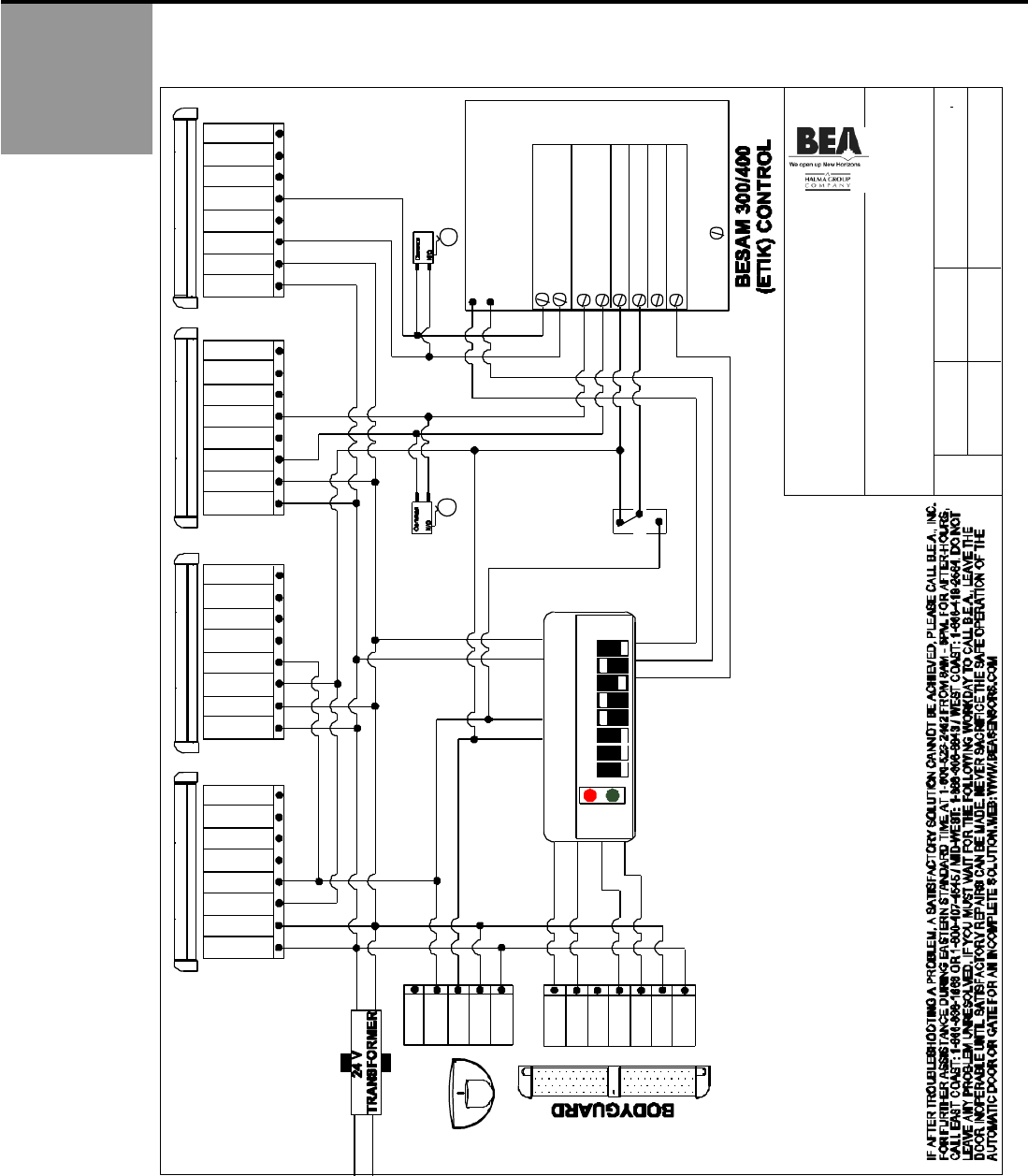
ADDENDUM –
SCHEMATICS
SIZE: DRAWN BY:
TITLE: BESAM 300/400 (ETIK) WITH
PASSPORT PLUS/ PARALLAX 2
SYSTEM (LO21B/U)
A
NOTES: 1) LO21B DIPSWITCHES: 1-5 (LOCK-OUT TIMING), #6 (DOWN/ON), #7 (UP/OFF), #8 (DOWN/ ON).
2) LO21B MAY BE SUBSTITUTED BY THE LO21U.
3) LH MOTOR SHOWN, REVERSE RED & BLACK ON RH
100 ENTERPRISE DRIVE
PITTSBURGH, PA 15275
PHONE: (412) 249-4100
FAX: (412) 249-4101
EMAIL: www.beasensors.com
REV BY:
KJG 80.0049.05
SCALE: DATE:
NONE 05 Aug. 08
PART NO:
SHEET
1 OF 1
115 VAC 24 VAC
DAT A + 7
blue
DAT A - 6
brow n
N.C. 5
N.O. 4
gree n
COM 3
white
POWER 2
black
POWER 1
red
16
15
12 COMMON
13 ACTI VATION
10 COMMON
11 SAFETY
STALL INPUT
BLACK
WHITE
HOLD VOLTAGE
} MOTOR VOLTAGE
See Note 3
"B" SWITCH
SET TO CLOSE
CONTACT AT
65 DEGREES.
STALL INPUT
17
18
AUTO
OFF
HO LD OPEN
RED
GRE EN
LO2 1B/U AP PLIC A TION D IP SW ITC H ES
B ES AM ETIK
OFF
ON
LO21B/U
RED
BROWN
ORANGE
RED/W H IT E
WHITE
GRAY
VIOLET
EAGLE
N.C. 5
N.O. 4
gree n
COM 3
white
POWER 2
black
POWER 1
red
GRE EN
BLUE
EM PT Y 1
INHIB IT G ND 2
INHIB IT + 3
N.C. 4
N.O. 5
CO M 6
POWE R 7
POWE R 8
LEFT APPRCH SIDE SSCAN
EM PT Y 1
INHIB IT G ND 2
INHIB IT + 3
N.C. 4
N.O. 5
CO M 6
POWE R 7
POWE R 8
LEFT SAFETY SID E SSCAN
EM PT Y 1
INHIB IT G ND 2
INHIB IT + 3
N.C. 4
N.O. 5
CO M 6
POWE R 7
POWE R 8
RIGHT APPRCH SIDE SSCAN
EM PT Y 1
INHIB IT G ND 2
INHIB IT + 3
N.C. 4
N.O. 5
CO M 6
POWE R 7
POWE R 8
RIGHT SAFETY SIDE SSCAN
BLACK
Y ELL OW
"B" SWITCH
SET TO CLOSE
CONTACT AT
65 DEGREES.
WJR

75.0084.06 20150618 Page 14 of 17
ADDENDUM -
SCHEMATICS
(Continued)
SIZE: DRAWN BY:
TITLE: BESAM MP VER. 6.3,4 DUAL, LO21B/U
PASSPORT PLUS / PARALLAX 2,
Q-DISCONNECT ON SAFETY SIDE
A
100 ENTERPRISE DRIVE
PITTSBURGH, PA 15275
PHONE: (412) 249-4100
FAX: (412) 249-4101
EMAIL: www.beasensors.com
REV BY:
KJG KJG 80.0043.07
SCALE: DATE:
NONE 4 JULY 2005
PART NO:
SHEET
1 OF 1
NOTES: 1) DO NOT POWER ALL SENSORS FROM MASTER CONTROL BOX. POWER SOME OF THE SENSORS OFF OF THE
SLAVE CONTROL.
2) ON BOTH CONTROLS SET PMD FUNCTIONS F20 = b, F19 = b , F18 = 0 0, F17=00, F16 = 05, F14 = a, F13 = a, F11 = 65
DEGREES.
3) ON THE MASTER CONTROL SET FUNCTION F12 TO 3 DEGREES LESS THAN F10.
4) THE WIRING OF THE SUPERSCANS IS USING THE QUICK DISCONNECT CABLES WITH PREWIRED CONNECTOR
ON SAFETY SIDE.
5) CONFIRM ALL SYNC LINES ARE PRESENT. ADDING SYNC LINES MAY BE REQUIRED.
6) DIPSWITCHES 1 THRU 5 LOCKOUT TIME. 6 (UP/OFF), 7 (UP/OFF), 8 (DOWN/ON).
YELLOW
VIOLET
RED/WHITE
GRAY
WHITE
BLACK
RED 19 + 18 VDC
14 SWITCH 2
BLUE
GREEN 4 COM
3 I IMP
9 MAT LOGIC
18 - 24VDC
17 + 24VDC
8 OFF
12 SYNC
11 O VDC
10 SYNC
3 I IMP
9 MAT LOGIC
13 SWITCH 1
5 P DET
2 P IMP
13 SWITCH 1
5 P DET
2 P IMP
YELLOW
BLUE
BROWN
BLACK
RED
GREEN
WHITE
ORANGE
SUPERSCAN QUICK
DISCONNECT CABLE
ORANGE
BROWN
( See note 6)
8 OFF
AUTO
OFF
HOLD OPEN
N.C. 5
N.O. 4
green
CO M 3
white
POWER 2
black
POWER 1
red
18 - 24VDC
17 +24VDC
RED
GRE EN
LO2 1 B/U D EFA ULT D IP SW ITC HES
B ES AM MP
OFF
ON
LO21B/U
EM PT Y 1
INHIB IT G ND 2
INHIB IT + 3
N.C. 4
N.O. 5
CO M 6
POWE R 7
POWE R 8
LEFT APPRCH SIDE SSCAN
EM PT Y 1
INHIB IT G ND 2
INHIB IT + 3
N.C. 4
N.O. 5
CO M 6
POWE R 7
POWE R 8
LEFT SAFETY SID E SSCAN
EM PT Y 1
INHIB IT G ND 2
INHIB IT + 3
N.C. 4
N.O. 5
CO M 6
POWE R 7
POWE R 8
RIG HT APPRCH SIDE SSCAN
EM PT Y 1
INHIB IT G ND 2
INHIB IT + 3
N.C. 4
N.O. 5
CO M 6
POWE R 7
POWE R 8
RIG HT SAFETY SIDE SSCAN
75.0084.06 20150618 Page 15 of 17
ADDENDUM -
SCHEMATICS
(Continued)
SIZE: DR AWN B Y:
B
100 ENTERPRI SE DRIVE
PITTSBURGH, PA 1 5275
PHONE: (4 12 ) 249-4100
FAX: (412) 249- 4101
EMAIL : www. beas ensors.c om
REV BY:
KJG TUC
SCALE: DAT E :
NO NE 19 OCT 2005
PART N O:
SHEET
1 OF 1
NOTES: USE CN3 FOR PO WER
EMPTY 1
IN HI BIT G ND 2
IN HI BIT + 3
N. O. 4
N. C. 5
CO M 6
POWER 7
POWER 8
RI G HT A P P R CH S ID E S S CA N
EMPTY 1
IN HI BIT G ND 2
IN HI BIT + 3
N. O. 4
N. C. 5
CO M 6
POWER 7
POWER 8
LE FT AP PR CH SI D E SSC AN
EAGLE
N.C. 5
N.O. 4
gr ee n
COM 3
white
PO W E R 2
bl ack
PO W E R 1
red
TIT LE: H ORTON C4190 C ONT ROL W IT H
P ARALLAX 2 S YSTE M
Q -DISCONNECT ON APPROACH SIDE
80.009 9.02
GREEN
WH I T E
BLACK
RE D
GREEN
WH I T E
BLACK
RE D
EMPTY 1
IN HI BIT G ND 2
IN HI BIT + 3
N. O. 4
N. C. 5
CO M 6
POWER 7
POWER 8
LE FT SA FET Y SID E SS CA N
EMPTY 1
IN HI BIT G ND 2
IN HI BIT + 3
N. O. 4
N. C. 5
CO M 6
POWER 7
POWER 8
RI G HT S A F E T Y S I DE S S C AN
BR OWN
WH I T E
BLACK
RE D
BR OWN
WH I T E
BLACK
RE D
1
2
3
4
5
6
7
8
9
10
11
12
C4190 CONTROL C3938 P/S
SUPERSCAN QUICK-
DISCON NECT CABLE
SUPERSCAN QUICK-
DISCON NECT CABLE
IF AFTER TROUBLESHOOTING A PROBLEM, A SATISFACTORY SOLUTION CANNOT BE ACHIEVED, PLEASE CALL B.E.A., INC. FOR FURTHER ASSISTANCE DURING EASTERN STANDARD TIME
AT 1-800-523-2462 FROM 8AM - 5PM. FOR AFTER-HOURS, CALL EAST COAST: 1-866-836-1863 OR 1-800-407-4545 / MID-WEST: 1-888-308-8843 / WEST COAST: 1-888-419-2564. DO NOT LEAVE
ANY PROBLEM UNRESOLVED. IF YOU MUST WAIT FOR THE FOLLOWING WORKDAY TO CALL B.E.A., LEAVE THE DOOR INOPERABLE UNTIL SATISFACTORY REPAIRS CAN BE MADE. NEVER
SACRIFICE THE SAFE OPERATION OF THE AUTOMATIC DOOR OR GATE FOR AN INCOMPLETE SOLUTION.WEB: WWW.BEASENSORS.COM
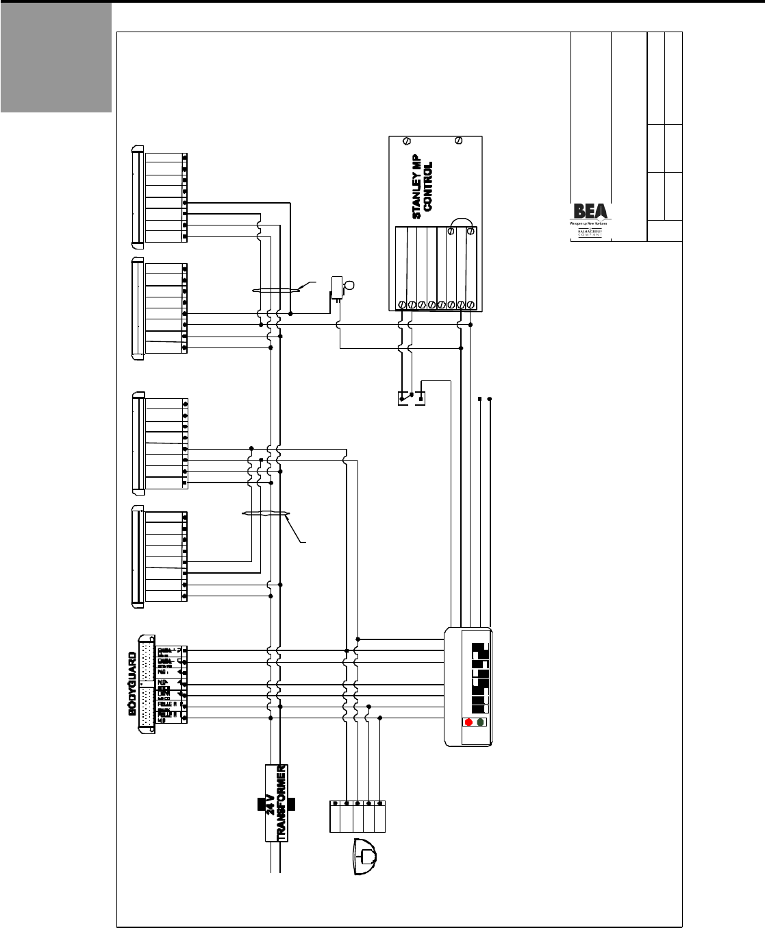
75.0084.06 20150618 Page 16 of 17
ADDENDUM -
SCHEMATICS
(Continued)
SIZE: DR AWN B Y:
B
100 ENTERPRI SE DRIVE
PITTSBURGH, PA 1 5275
PHONE: (4 12 ) 249-4100
FAX: (412) 249- 4101
EMAIL : www.beasensor s.c om
REV BY:
KJG TUC
SCALE: DAT E :
NO NE 02 DEC 2005
PART N O:
SHEET
1 OF 1
NOTES: 1 ) MAGIC FORCE AUX. SWIT CH #4 SHOULD OPEN AT APPROX. 65- 70 DEGREES. FOR MAG IC SWING REFER TO INHIBIT SWITCH BEA PT# 10 SSINHL OR 10SSINHR.
2 ) THE BODYGUARD RELAY OUTPUT FUNCTION MUST BE CHANGED TO #2.
3 ) SHOWN LH,RH MAG IC SWING AND RH MAGIC FORCE FOR LH MAGIC FORCE REVERSE RED AND BLACK WIRES.
4 ) DOOR CONTROL SW2 SWITCH BANK SET DIPSWITCH # 1 & 3 T O THE O FF (TIMER) POSITION.
5 ) JUMPER 6 & 8.
6 ) INSTALL BLUE WIRE INTO PIN 6. INSTALL WHITE WIRE INTO PIN 1
EMPTY 1
IN HI BIT G ND 2
IN HI BIT + 3
N. C. 4
N. O. 5
CO M 6
POWER 7
POWER 8
LEF T A PPR CH SIDE SSC AN
EMPTY 1
IN HI BIT G ND 2
IN HI BIT + 3
N. C. 4
N. O. 5
CO M 6
POWER 7
POWER 8
R IGH T A PPR CH S IDE SSC AN
EAGLE
N. C. 5
N. O. 4
green
CO M 3
wh ite
PO WER 2
black
PO WER 1
red
TITLE: STANLEY MP CONTROL WITH LO-21P
PARALLAX II SYSTEM Q-DISCONNECT
ON APPROACH SIDE
80.018 7.04
GREEN
WH I T E
BLACK
RE D
GREEN
WH I T E
BLACK
RE D
EMPTY 1
IN HI BIT G ND 2
IN HI BIT + 3
N. C. 4
N. O. 5
CO M 6
POWER 7
POWER 8
R IGH T SA F ETY SIDE SSC AN
EMPTY 1
IN HI BIT G ND 2
IN HI BIT + 3
N. C. 4
N. O. 5
CO M 6
POWER 7
POWER 8
LEF T S AFET Y SIDE S SCAN
BR OWN
BLUE
BLACK
RE D
BR OWN
BLUE
BLACK
RE D
RED
GREEN
LO21P D EFAULT DIP SWITCHES
FOR STANLEY MP
OFF
ON
LO21 P
BROWN
GREEN
BLUE
VIO LET
GRAY
ORANGE
WH ITE
RED / WH ITE
BLACK/ W HITE
HO LD OPEN
AUTO
OFF
24 VAC
115 VAC
SUPERSCAN QUICK
DISCON NECT CABLE
SUPERSCAN QUICK
DISCON NECT CABLE
Common
N/O
N/C MAGI C FOR CE
AUXI LLARY SWI TC H 4
(SEE NOTE # 1)
( S ee N o te # 2 )
1 COMMON
2 OPERATE
3 SENSOR OP
4 12 VAC
5 12 VAC
6 AUX INPUT
7 SAFETY/STALL
8 COMMON
STALL TORQ UE
(See Note #4)
IN STAL L JUMPER
IF N O BREAKOU T
SWI TC H.
BLACK -
RED + BLACK
WH I T E
-
+
YEL LO W
MOTOR VOLTAGE (AT MOTOR)
( S ee N o te # 3)
IF AFTER TROUBLESHOOTING A PROBLEM, A SATISFACTORY SOLUTION CANNOT BE ACHIEVED, PLEASE CALL B.E.A., INC. FOR FURTHER ASSISTANCE DURING EASTERN STANDARD TIME
AT 1-800-523-2462 FROM 8AM - 5PM. FOR AFTER-HOURS, CALL EAST COAST: 1-866-836-1863 OR 1-800-407-4545 / MID-WEST: 1-888-308-8843 / WEST COAST: 1-888-419-2564. DO NOT LEAVE
ANY PROBLEM UNRESOLVED. IF YOU MUST WAIT FOR THE FOLLOWING WORKDAY TO CALL B.E.A., LEAVE THE DOOR INOPERABLE UNTIL SATISFACTORY REPAIRS CAN BE MADE. NEVER
SACRIFICE THE SAFE OPERATION OF THE AUTOMATIC DOOR OR GATE FOR AN INCOMPLETE SOLUTION.WEB: WWW.BEASENSORS.COM
( S ee N o te # 6 ) ( S ee N o te # 6 )
75.0084.06 20150618 Page 17 of 17
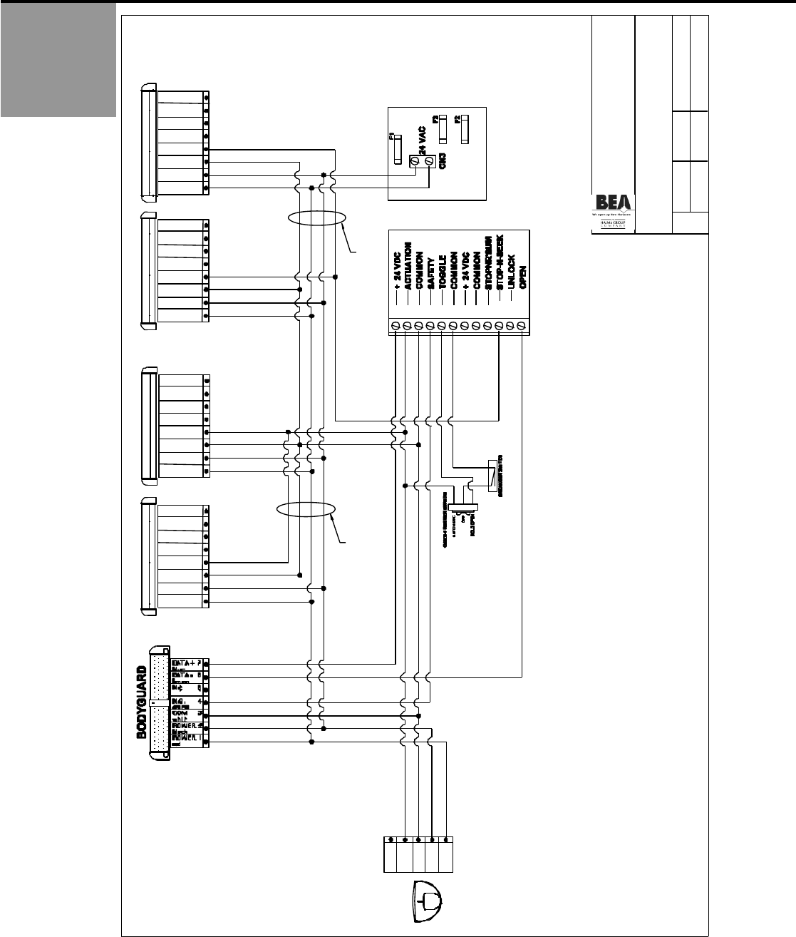
ADDENDUM -
SCHEMATICS
(Continued)
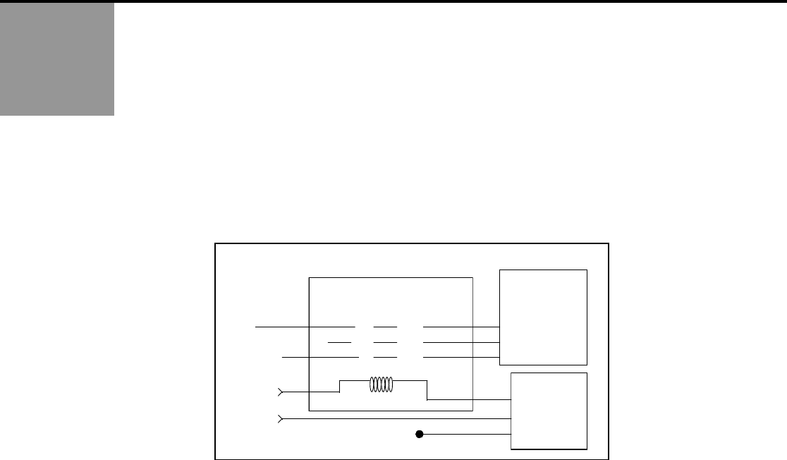
If a wall or a guardrail is detected by the SuperScan in the opening cycle, the SuperScan will need to be inhibited before
the detection is allowed to stall the door. For some operators, the back check switch can be used to shut the SuperScan
off before the detection occurs. It there is a voltage present across the leads of the back check switch; a relay must be
used (as shown below) to supply a dry contact to the SuperScan. When this is performed, the switch is used to toggle
voltage on and off at the coil of the relay. The relay, in turn, has 2 sets of isolated outputs: One to trigger the backcheck
function at the door control, and the other to inhibit the circuit for the stall function. When the door reaches the backcheck
position and triggers the limit switch, the SuperScan, although in detection, is inhibited, thus allowing the door to continue
to open normally through backcheck.
The relay should be energized (voltage applied) when the door is in any position other than backcheck. In this fashion, the
configuration lends itself to fail-safe operation. That is, if the relay fails (power loss at relay) the door will operate as if in
backcheck.
A 24-volt isolation relay is available from BEA, Inc. with the part number: 10REL24V. Below is a diagram on the wiring of
the relay with a typical N.O. stall circuit. If your stall circuit is N.C. wire a jumper from number 1 to 4 to allow for inhibit at
the backcheck angle.
1
4
7
2
5
8
3
6
9
NC
NO
COM
A(-)B (+)
24 V AC
24 V AC
NC
NO
COM
NC
NO
COM
Microswitch
COM
NC
Back Check
Connections on
Control Box
NO
NC
COM
NO
24 VAC Relay (Idec RR3B-U)
cap off
Safety
SuperScan
NO
Door Control
Safety
ISO-24 (24V AC Isolation Relay) / BEA PN: 10REL24V
