BEST A2 System Service Manual
User Manual: BEST A2 System Service Manual Service Manual
Open the PDF directly: View PDF ![]() .
.
Page Count: 62
- Contents
- Figures
- 1 Getting Started
- 2 Overview of a Masterkey System
- 3 Parts
- 4 Options and Applications
- 5 Changes to the A2 System
- 6 Service and Maintenance
- A2 System basic procedures overview
- Developing a key control system
- Purpose of a key control system
- Objectives of a key control system
- Updating key and core records
- G-Series cards and equipment
- Procedures to administer your key control system
- Sample key agreements
- Issuing and returning keys
- When keys are lost or stolen
- Adding, removing and changing cores
- Planning for emergencies
- Parts servicing
- General core maintenance
- A Glossary
- B Index

SERVICE MANUAL
SERVICE MANUAL
CREDITS/COPYRIGHT
©2001 Best Lock Corporation dba Best Access Systems. All rights reserved. Printed in
the United States of America.
Information in this document is subject to change without notice and does not
represent a commitment on the part of Best Access Systems. The software described in
this document are furnished under a license agreement or nondisclosure agreement.
This publication is intended to be an accurate description and set of instructions
pertaining to its subject matter. However, as with any publication of this complexity,
errors or omissions are possible. Please call your BEST distributor or Best Access
Systems at (317) 849-2250 if you see any errors or have any questions. No part of this
manual and/or databases may be reproduced or transmitted in any form or by any
means, electronic or mechanical, including photocopying, recording, or information
storage and retrieval systems, for any purpose, without the express written permission
of Best Access Systems.
This document is distributed as is, without warranty of any kind, either express or
implied, respecting the contents of this book, including but not limited to implied
warranties for the publication’s quality, performance, merchantability, or fitness for any
particular purpose. Neither Best Access Systems, nor its dealers or distributors shall be
liable to the user or any other person or entity with respect to any liability, loss, or
damage caused or alleged to be caused directly or indirectly by this publication.
Masterkey codes are owned by BEST and constitute confidential and proprietary
information. BEST will seek to protect Masterkey codes by all legal means necessary,
including, but not limited to, seeking injunctive relief and/or a suit for damages.
The Life Safety Code is a registered trademark of the National Fire Protection
Association.
Written and designed by Best Access Systems and Avalon Group, Inc., Indianapolis,
Indiana.
T61803 Rev – 1413160 ER7991-6 October 2001

A2 System Service Manual iii
CONTENTS
FIGURES VII
GETTING STARTED 1–1
Introduction 1–1
Documentation package 1–2
Technical support 1–2
Support services 1–2
Telephone and web technical support 1–2
Training seminars 1–2
OVERVIEW OF A MASTERKEY SYSTEM 2–1
Understanding the BEST difference 2–2
Benefits 2–2
Support from BEST 2–2
Training 2–2
BEST warranty 2–3
Defining a masterkey system 2–4
Definition of a masterkey system 2–4
General design guidelines 2–4
Product family diagram 2–5
Interchangeable core 2–6
Keys 2–6
Keyways 2–7
Codes 2–8
System organization and size 2–8
System security 2–9
Key and core control 2–10
Common control problems 2–10
G-Series forms 2–10
Keystone 600 Software 2–10

Contents
iv A2 System Service Manual
PARTS 3–1
Overview of the BEST core 3–2
Core with segments, springs, and caps 3–2
Cross-section view of a core 3–2
Overview of the BEST key 3–3
Diagram of an operating key 3–3
Tools 3–4
Stamping tools 3–5
Lubrication items 3–5
OPTIONS AND APPLICATIONS 4–1
Keyway options 4–2
Special options and applications 4–3
CHANGES TO THE A2 SYSTEM 5–1
Determining your needs 5–2
Questions to consider 5–2
Working with BEST 5–2
Surveying the facility 5–2
Designing the schematic 5–4
Obtaining BEST codes 5–7
Re-lock options 5–9
SERVICE AND MAINTENANCE 6–1
A2 System basic procedures overview 6–2
Combinating cores 6–2
Cutting keys 6–3
Stamping cores and keys 6–3
Installing cores 6–4
Developing a key control system 6–5
Purpose of a key control system 6–5
Objectives of a key control system 6–5
Updating key and core records 6–5
G-Series cards and equipment 6–6
Procedures to administer your key control system 6–13
Sample key agreements 6–13
Issuing and returning keys 6–14
When keys are lost or stolen 6–15
Adding, removing and changing cores 6–15
Planning for emergencies 6–16
Parts servicing 6–17
General core maintenance 6–17
GLOSSARY A–1
INDEX B–1

A2 System Service Manual vii
FIGURES
OVERVIEW OF A MASTERKEY SYSTEM
Product family diagram 2–5
Sample masterkey hierarchy 2–7
PARTS
Segments, springs, and caps 3–2
Cross-section view of core 3–2
Standard key features 3–3
Tools used for servicing cores and keys 3–4
Stamping tools 3–5
Lubrication items 3–5
CHANGES TO THE A2 SYSTEM
Sample site survey 5–3
Sample keying schematic for buildings 5–5
Sample keying schematic for departments 5–6
Sample BEST code sheet 5–8
SERVICE AND MAINTENANCE
Door Number card 6–7
Core Number card 6–7
Key Marking card 6–8
Employee Name card 6–8
Key Request card 6–9
Key Receipt card 6–9
Lock Request card 6–10


A2 System Service Manual 1–1
1GETTING STARTED
INTRODUCTION
The A2 System Service Manual contains essential
information to help you maintain your A2 System.

Getting Started
1–2 A2 System Service Manual
DOCUMENTATION PACKAGE
The following documentation is available to help you with the
installation, start-up, and maintenance of your A2 System.
The installation and assembly instructions also can be ordered
separately:
TECHNICAL SUPPORT
Support
services
When you have a question about the A2 System, your first resource for
help is the A2 System Service Manual. If you cannot find a satisfactory
answer, contact your local BEST Representative.
Telephone and
web technical
support
A factory-trained Certified Product Specialist (CPS) is available in your
area whenever you need help. Before you call, however, please make
sure that the product is in your immediate vicinity, and that you are
prepared to give the following information:
■what happened and what you were doing when the problem arose
■what you have done so far to correct the problem.
Best Access Systems Representatives provide telephone technical
support for all A2 System products. You may locate the Representative
nearest you by calling (317) 849-2250 Monday through Friday, between
7:00 a.m. and 4:00 p.m. eastern standard time; or visit the web page,
www.BestAccess.com.
Training
seminars
BEST holds training sessions for its customers. The seminars are
specifically designed for BEST end-users who have a registered BEST
Masterkey system and registered BEST security equipment. If you are
interested, you may contact your local BEST Representative for details.
Document Title Doc. No.
Core and Key Service Manual T35527
Key Combinator Service Manual T35532
Keystone 600 Getting Started Guide E-774

A2 System Service Manual 2–1
2OVERVIEW OF A MASTERKEY
SYSTEM
This chapter discusses the benefits of a BEST system
and defines how a masterkey system works. It also
describes some of the components of a masterkey
system such as interchangeable cores, keys, and
codes. Finally, it provides guidelines for protecting a
masterkey system.

Overview of a Masterkey System
2–2 A2 System Service Manual
UNDERSTANDING THE BEST DIFFERENCE
Best Access Systems has positioned itself to be your complete provider
for access security systems. Our sales team has been trained to analyze
the specific needs of your facility and recommend products and
solutions that will most effectively address your access control
requirements.
Benefits By choosing BEST, you are automatically guaranteed resources to help
you with all of your security needs including:
■full installation services for all systems’ products
■staff training services for various product lines and processes
■24-hour assistance and consultation for any security need
■full specification preparation for new construction
■superior product availability and delivery.
Support from
BEST
Your BEST Representative will support you in all aspects of
administering the system provided by BEST including:
■security consulting for all phases of security administration
■designing customized access control systems
■customizing a masterkey system for any size facility
■maintaining accurate records of the system
■expanding the system in the future.
Training In-house system maintenance and service
BEST Representatives provide local inventories, expertise, and training
in servicing BEST’s security system. Formal training is available to help
you develop an in-house service department as well as to give you the
ability to:
■combinate cores
■recombinate cores
■cut keys
■program and maintain electronics
■maintain lock hardware.
Formal training is available from BEST with special “Advanced Systems
Curriculum” training being offered by the corporate factory
headquarters.

Overview of a Masterkey System
A2 System Service Manual 2–3
BEST warranty BEST warrants that all of its products sold under its trade name are free
of defects in materials, workmanship and operation, normal wear and
tear excepted, for a period of three years from the date of sale to the
original purchaser. BEST does not, however, warrant against defects
that may be due to improper uses or installation, poor or no
maintenance, shipping and/or handling, improper storage, accident,
abuse or unauthorized service. BEST cannot be responsible for services
provided by other companies to the system. Contacting your BEST
Representative for installation and maintenance needs will ensure that
you keep your warranty. The liability of BEST under this warranty is
limited to the repair or replacement of any product covered by the
warranty.

Overview of a Masterkey System
2–4 A2 System Service Manual
DEFINING A MASTERKEY SYSTEM
Definition of a
masterkey
system
A masterkey system is often misunderstood because it is not a tangible
product and can have many variations. A BEST Masterkey system can be
customized to meet any particular customer needs.
Masterkeying is a mathematical process that shows the number of
different combinations available within a given plan and allows all cores
to be combinated into your system. It also assists the user in controlling
the doors that people can access in the given facility.
Several security levels of keys are usually able to operate a single lock in
a masterkey system. This feature offers flexibility as well as control to
your system. Careful planning and consultation with your BEST
Representative can help you maximize the benefits and avoid common
pitfalls of a masterkey system. In most systems, 7-pin cores are used
because they permit more combinations and allow greater flexibility for
future expansion.
General design
guidelines
BEST Representatives use the following guidelines when designing a
customized masterkey system for the customer:
■Design the keying system around the function of the building and
not the actual organization, if possible.
■Develop a simple design.
■Try to predict where, when, and how people move throughout the
building.
■Plan for any future expansion that may be needed.
■Recognize the families of keys that are established, because they can
restrict the flexibility of the system.
Moreover, once a system is established, it is not necessary to use all of
your codes at one time. Codes may be set up as needed. Then, if growth
occurs, BEST refers to its own secure files for the remaining available
combinations. This activity is conducted as directed by the customer. It
is the customer’s responsibility to keep track of which core markings
have been used in a given series.

Overview of a Masterkey System
A2 System Service Manual 2–5
Product family
diagram
Figure 2.1 Product family diagram
C
9
8
7
6
5
4
3
2
1
0
CAUTION
PINCH POINT
ALIBRATE
YSTEM A2
Key combinator
Core capping press
Core
Key blank
Combinating kit
Keystone 600 software

Overview of a Masterkey System
2–6 A2 System Service Manual
Interchangeable
core
The standard figure-8 core that is interchangeable throughout the entire
product line is a major feature of BEST. This interchangeability permits
BEST locks of any type, size, or style to be masterkeyed into one system.
Therefore your system can easily expand to include new facilities. Also,
no BEST core needs alterations to fit any other BEST lock. You simply
remove the core with the control key and insert a new core that
operates by different keys. This unique feature lets you perform a re-
lock in seconds. See page 5–9.
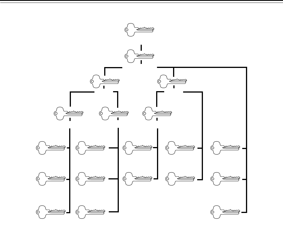
Keys It is important to understand several key terms to more fully
comprehend the concepts of masterkeying. See Figure 2.2.
Control key
The control key installs and removes the interchangeable core in your
BEST system. The control key has the same security level as a
grandmaster and must receive the same level of protection.
Grandmaster key
The grandmaster key operates all locks in a masterkey system (unless
locks are specifically excluded from the grandmaster for security or
safety reasons such as cash boxes, drug cabinets, hazardous waste areas,
and so forth).
Master key
The master key operates a large group of locks. For example, one
master key can have access to an entire building, floor, or department.
Submaster key
The submaster key operates a smaller group of locks that are part of a
master group.
Operating key
The individual key is also known as the operating key and is the lowest
level key. This key operates only one lock or keyed-alike group of locks.
(This type of key is also called “change key” in the locksmith industry.)
It is important to note that keying is not limited to just the organization
of the keys listed above. More levels in the hierarchy may be created if
needed. For example, a sub-submaster key level may be added.
Overview of a Masterkey System
A2 System Service Manual 2–7
Keyways The keyway of a core is a specific design or shape of the key blade and
is manufactured into the core plug. This specific design keeps keys of
other keyways from working in a dissimilar core. The keyway shapes
can be grouped into the following categories:
■Standard keyways
■Restricted keyways
■Patented keyways.
Figure 2.2 Sample masterkey hierarchy
Control
Grandmaster
Master Master
Submaster Submaster Submaster
Operating Operating Operating Operating Operating
Operating Operating Operating Operating Operating
Operating Operating Operating

Overview of a Masterkey System
2–8 A2 System Service Manual
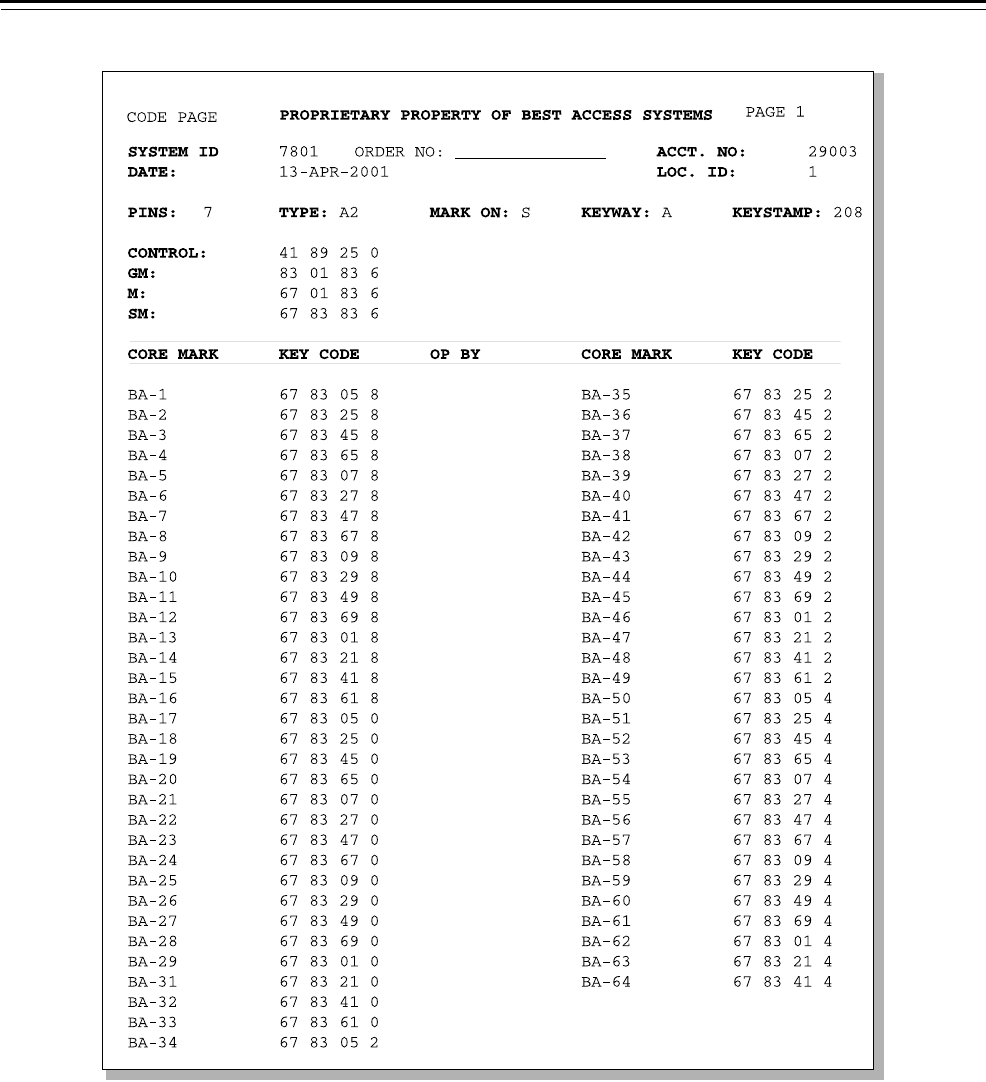
Codes One of the most significant elements of a masterkey system is the codes
on which the entire system is based. Codes are the number sequences
that directly relate to key cuts and indirectly relate to the pin segments
or combinations within the interchangeable core. Codes originate at the
corporate headquarters and are used by BEST offices to establish
systems around the world. All codes remain proprietary property of
BEST.
Codes are only supplied to the customer when BEST authorized service
equipment has been ordered and received. Once generated, the codes
arrive in the form of a code sheet or bitting list. This sheet then
becomes a printed record of your keying system. It contains
information about your system that is highly confidential. See page 5–8
for an example of a code sheet.
SYSTEM ORGANIZATION AND SIZE
The size of your system is determined by the following factors:
■The number of individual locks you need
■The pin size of your cores
■The code system you need.
The number of actual locks you require is taken from the information
you received from the site survey. A general rule of thumb is to estimate
your future core needs by doubling the number of locks determined by
the site survey. Then you will have codes available when you need to re-
key one or several locks due to lost or stolen keys. Planning for extra
codes will also let you add an additional building or wing under the
same system.
The pin size of cores refers to the number of barrels in each core. BEST
uses 7-pin cores as a standard in order to provide greater flexibility in
the number of combinations that can be generated. However, if your
existing system uses 5-pin or 6-pin cores, BEST offers these pin sizes as
well. Using 5-pin or 6-pin, though, will decrease the number of total
combinations that are available to you.
Manufacturing tolerances, as designed, are a vital factor in consistent
key control. For each specific system, keys and core segments must be
designed to mate exactly as coded. BEST holds a very close tolerance
throughout its product lines.
Your BEST Representative can help you determine which options not
only meet your facility’s current needs, but also provide maximum
flexibility and efficiency as your system evolves.

Overview of a Masterkey System
A2 System Service Manual 2–9
SYSTEM SECURITY
To increase the level of security within your system, you need to
protect sensitive security products or information. These may include:
■Code sheets
■Service equipment
■Authorized security personnel contacts
■Key/core inventory.
BEST will help you with these procedures by maintaining code records
at local BEST offices. In addition, authorized security contacts are kept
on file. These contacts are people who are responsible for receiving all
products and information. Security policies and procedures such as
these help assure the integrity of your keying system.

Overview of a Masterkey System
2–10 A2 System Service Manual
KEY AND CORE CONTROL
A good mechanical locking system involves more than hardware. A key
and core control system is a recording and filing plan that provides
complete information on keying, doors, locks, and personnel. The
system should include formal policies and procedures to regulate the
distribution and control of key, core and code issuance. The following
five elements must be controlled in all lock and key systems in order to
maintain security:
■Keys
■Cores
■Forms
■Doors
■People.
Common
control
problems
Based on a survey conducted by BEST, security system users revealed
the following problems with managing and administering the locking
system:
■Loss of keys—either lost or stolen
■Not retrieving keys from employees that have been replaced or have
retired
■Management indifference to security problems
■Theft—internal and external
■Too many keys issued
■Poor management of records resulting in keys being misplaced or
stolen by employees within the facility
■Code expansion without BEST involvement
■Too many people involved with the system.
G-Series forms Keeping accurate and up-to-date records is essential for the overall
management of a BEST system. It is important to use adequate forms, in
detail, to account for all keys/cores in your facility. The BEST G-Series
form system provides color coding, cross-referencing, and space for
continuous relocks and key changes. Contact your BEST Representative
to obtain these forms.
Keystone 600
Software
For larger systems (systems with 100 or more users), the Keystone 600
Software is the recommended means of maintaining the A2 System.
BEST’s Keystone 600 key and core control software is a valuable tool for
managing records. This user-friendly, Windows-based system allows for
expedited entry of data and the generation of multiple standard reports.
This program records, cross-references, and accesses all key and core
information. Modeled after the proven G-Series form system,
Keystone 600 helps you to efficiently make the transition from a manual
system to a computer.

A2 System Service Manual 3–1
3 PARTS
The following pages contain descriptions and figures
for BEST A2 System cores, keys, and tools for
servicing them. To order these items, refer to the
Core and Key Service Manual (T35527).
Parts
3–2 A2 System Service Manual
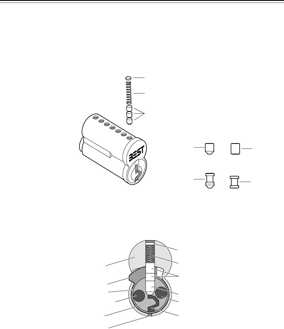
OVERVIEW OF THE BEST CORE
Core with
segments,
springs, and
caps
Cross-section
view of a core
Figure 3.1 Segments, springs, and caps
Segments
Spring
Cap
Standard
beveled
segment
Standard flat
segment
Spooled
beveled
segment Spooled flat
segment
Figure 3.2 Cross-section view of core
Core body
Control lug
Throw pin hole
Core plug
Ejector hole
Cap
Top segments
Spring
Bottom segment
Throw pin hole
Keyway
Core sleeve
Parts
A2 System Service Manual 3–3
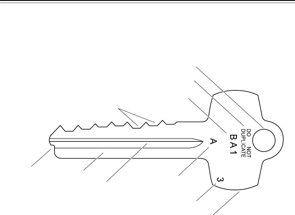
OVERVIEW OF THE BEST KEY
Diagram of an
operating key
Figure 3.3 Standard key features
Keyway milling
Serialization code
(optional)
Series marking code
Key stop tip Key blade
Key stamp
Keyway designation
(optional)
Key cuts
Key bow
Key chain hole
Parts
3–4 A2 System Service Manual
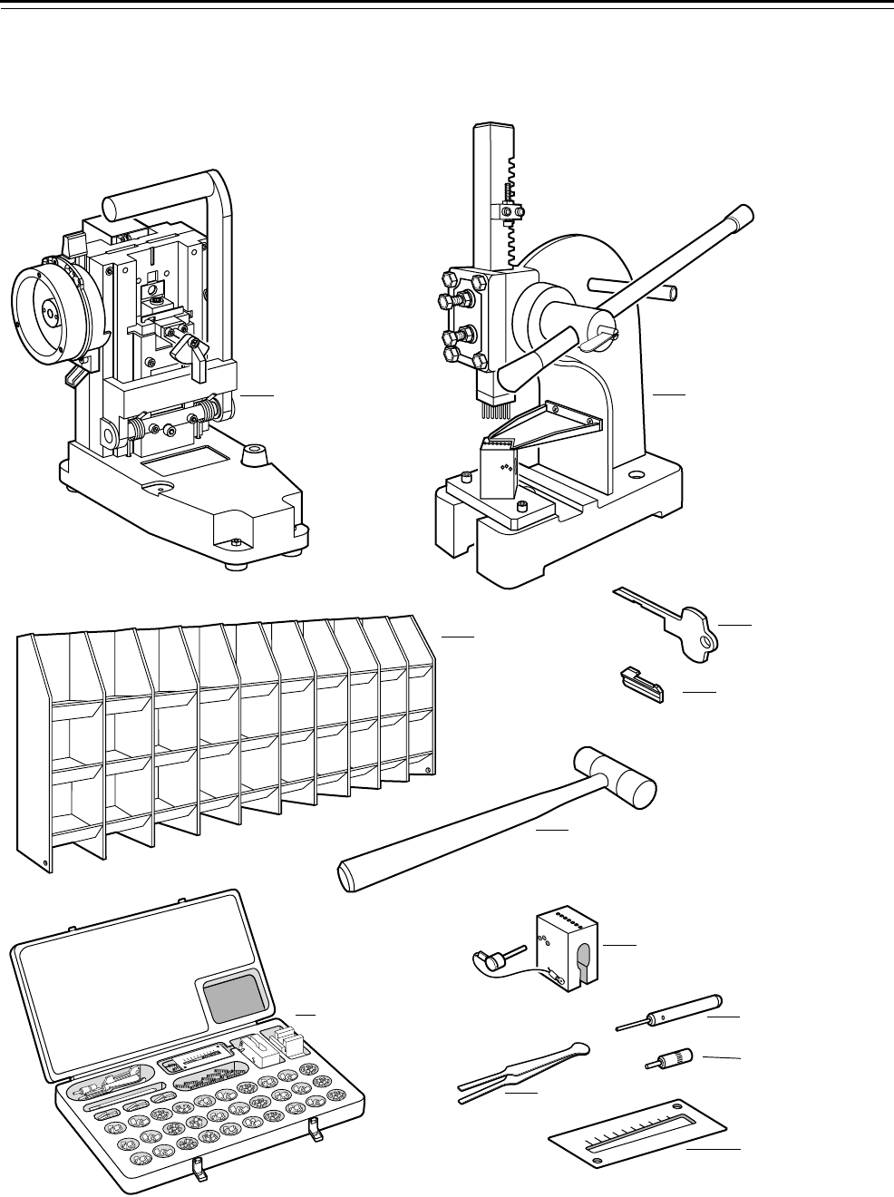
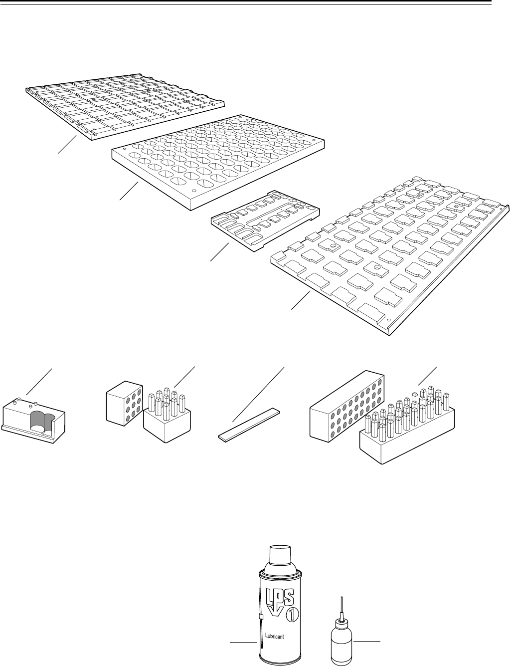
TOOLS
The following tools are used for servicing cores and keys.
Figure 3.4 Tools used for servicing cores and keys
9
8
7
6
5
4
3
2
1
0
C
9
8
7
6
5
4
3
2
1
0
Key Combinator Core capping press
Combinating bin
Combinating hammer
Complete combinating kit
Capping block
Ejector pin
Tweezers
Hand capping pin
Key cut indicator
Keyway blockout blade
Extractor key
Parts
A2 System Service Manual 3–5
Stamping tools The following tools are used for stamping cores and keys in your
system.
Lubrication
items
The following items are used to lubricate cores.
Figure 3.5 Stamping tools
Core stamping plate—
face only (for 87 cores)
Core/key marking plate
Key stamping plate (for 55 keys)
Core/key
marking block
Number dies Letter diesMagnetic strip
Figure 3.6 Lubrication items
LPS spray can Graphite gun
Core stamping plate—
side only (for 50 cores)

Parts
3–6 A2 System Service Manual

A2 System Service Manual 4–1
4 OPTIONS AND APPLICATIONS
This chapter contains keyway options and special
core options with their applications for the BEST
A2 System.

Options and Applications
4–2 A2 System Service Manual
KEYWAY OPTIONS
The following table describes possible keyway options that BEST offers
for the A2 System.
Keying option†
† Multi-milled key blanks are available for up to a family of four keyways. Keyway
families are typically used for only the highest key levels. These keyways are chosen
when you have an existing system and have no available codes; or you have a large
system and need more flexibility.
Description
Standard keyway BEST offers standard keyways for general use by customers
that are compatible with existing systems and provide a cost
effective means for system expansion.
Restricted keyway BEST offers non-patented keyways, which BEST restricts by
volume and proximity usage for limited distribution.
Patented keyway BEST offers patented keyways that cannot legally be
duplicated by other manufacturers.

Options and Applications
A2 System Service Manual 4–3
SPECIAL OPTIONS AND APPLICATIONS
The following table describes special core options that BEST offers for
the A2 System and gives examples for when they are used.
Option Description Application
Key trap core When the key is inserted into the core and is
turned, the key is trapped in the core. The key
cannot be returned vertically nor withdrawn
from the core. The core and trapped key must
be drilled out of the lock.
This special core is modified at the factory to
match the key that you want to trap.
Eliminates a key from the system
by trapping it in the core. This
option is useful if a key has been
lost, or if someone has a key and
will not return it.
Keyway blockout blade†This blade prevents any and all keys from being
inserted in a core. A special extractor key must
be used in order to remove the blockout blade
from the keyway.
Prevents keys from having access
to a given entrance. This option is
useful to have in case of a natural
disaster or a specified job action
such as a strike or lockout.
Wear resistant core Hardened stainless steel segments are used as
the bottom segments in each barrel of the core.
Provides longer life for cores in
high traffic areas such as entry
doors or other frequently used
doors.
Pick resistant core Spooled segments are used as the top and
bottom segments in each barrel of the core.
Provides enhanced resistance to
picking the core. This option is
useful for high security areas such
as narcotics rooms, special
equipment rooms, or cash offices.
Drill resistant core Hardened ball bearings are used in the throw
pin holes and hardened stainless steel segments
are used at the top and bottom segments in the
first two barrels of the core.
Provides enhanced resistance to
drilling the core. This option
provides an added measure of
security for areas listed above.
Pick and drill resistant core Hardened ball bearings are used in the throw
pin holes and hardened stainless steel segments
are used as the top and bottom segments in the
first two barrels of the core. Spooled segments
are used as the top and bottom segments in
each remaining barrel of the core.
Provides enhanced resistance to
picking and drilling of the core.
This option provides an added
measure of security for areas listed
above.
Core dust cover Stainless steel spring-loaded dust cover is
installed over the keyway.
Prevents the keyway from
accumulating dust and dirt. This
option is useful for cores exposed
to the elements such as doors in
high humidity climates, selected
doors in chemical plants, or for
low use exterior doors.
Note: If the core is housed in a
cylinder, use the cylinder dust
cover instead of the core dust
cover for maximum protection.
† See page 3–4 for illustrations of the keyway blockout blade and extractor key.

Options and Applications
4–4 A2 System Service Manual

A2 System Service Manual 5–1
5 CHANGES TO THE A2 SYSTEM
This chapter contains guidelines for determining
your A2 System needs, guidelines for working with
BEST when making changes to the A2 System, and
also includes possible re-lock options.

Changes to the A2 System
5–2 A2 System Service Manual
DETERMINING YOUR NEEDS
Questions to
consider
There are several questions that customers should consider when
assessing what changes need to be made to the A2 System including the
following:
■How many keys did I originally plan for?
■How many new locks do I need now and approximately how many
will I need in the future?
■How many codes do I have left for my system?
■How many master keys do I want (see page 2–8)?
■Are there any special options or adaptations that I want
(see page 4–3)?
■Do I have specific security needs or concerns about
re-locks (see page 5–9)?
The way that your system was originally customized may affect how
you go about making changes or expanding the system. For instance, if
you did not originally plan to add on to your facility, then there may not
be enough codes saved to do so. It is necessary to contact your BEST
Representative to help you determine how to resolve any issues that
may arise.
WORKING WITH BEST
Surveying the
facility
After the initial assessment of the system has been made, a physical site
survey is conducted for new areas of the facility. Your BEST
Representative will inspect and assess all of the requirements associated
with securing your facility. The goal of a site survey is to systematically
gather information that allows a thorough analysis of each access point.
This analysis helps identify all necessary hardware requirements. It also
organizes valuable information about the feasibility of integrating
additional buildings, wings, and so forth into a system. The survey can
then be used with the system schematic to determine how each lock is
to be keyed/programmed. For an example of a site survey, see
Figure 5.1.
Changes to the A2 System
A2 System Service Manual 5–3
Figure 5.1 Sample site survey

Changes to the A2 System
5–4 A2 System Service Manual
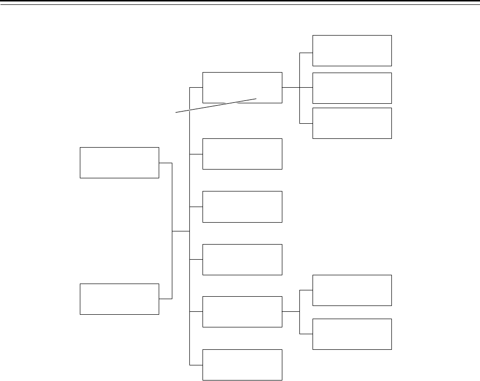
Designing the
schematic
The keying schematic is a plan or blueprint that illustrates the various
levels of security you need for the BEST system. These levels are defined
and designated into specific groups. The schematic design is similar to
an organizational chart, as shown in Figure 5.2 and Figure 5.3.
General guidelines
When designing a masterkey system schematic, BEST Representatives
follow these guidelines:
■Initially structure a control and grandmaster level.
■Determine how the facility is to be grouped as far as buildings,
locations, wings, floors, departments, and so forth. The first
grouping or level usually determines the master level of keys.
■Develop a second level of control within a building, floor, or
wherever necessary by creating a submaster group. Additional levels
or groups can be created if needed.
■Determine codes for masters, submasters, and any additional
groupings.
■Design special levels of access or restriction for additional system
flexibility.

Changes to the A2 System
A2 System Service Manual 5–5
Figure 5.2 Sample keying schematic for buildings
Sub-submaster key ACB
2nd Floor
(64)
Submaster key AB
Miles Hall
(256)
Submaster key AC
Wyatt Hall
(256)
Submaster key AD
Dixon Hall
(256)
Submaster key AA
Alumni Hall
(256)
Submaster key CA
Book Store
(64)
Submaster key CB
Food Service
(64)
Submaster key CC
Health Service
(64)
Submaster key DA
Mechanical
(64)
Submaster key DB
Grounds
(64)
Submaster key EA
Classrooms
(16)
Submaster key EB
Entrance
(16)
Submaster key EC
Custodial
(16)
Control key
Submaster key GA
Gym
(256)
Submaster key GB
Stadium
(256)
Submaster key GC
Tennis
(64)
Sub-submaster key ACA
1st Floor
(64)
Sub-submaster key ACC
3rd Floor
(64)
Master key G
Sports
(1024)
Master key F
Library
(256)
Master key E
Academic Buildings
(256)
Master key D
Physical Plant
(256)
Master key C
Student Center
(256)
Master key B
Administration
(64)
Master key A
Housing
(4096)
Grandmaster key
Number of allocated
combinations
Changes to the A2 System
5–6 A2 System Service Manual
Figure 5.3 Sample keying schematic for departments
Submaster key AB
Accounting
(16)
Submaster key AC
Gift Shop
(16)
Submaster key AA
Purchasing
(16)
Submaster key EA
Physical Therapy
(16)
Submaster key EB
Occup. Therapy
(16)
Control key
Master key F
Physical Plant
(256)
Master key E
Therapy
(64)
Master key D
Radiology
(64)
Master key C
Outpatient
(256)
Master key B
Surgery
(256)
Master key A
Administration
(256)
Grandmaster key
Number of allocated
combinations

Changes to the A2 System
A2 System Service Manual 5–7
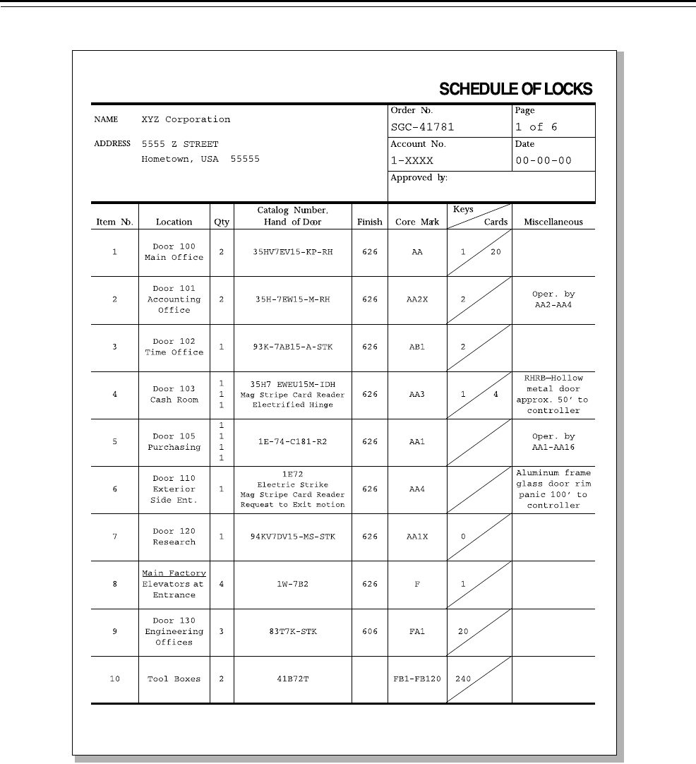
Obtaining BEST
codes
The code sheets you receive from BEST are a list of numbers used for
cutting keys and for determining pin segments when combinating
cores. See Figure 5.4.
Warning!
Do not try to create your own coding system. Improper code
design could lead to security violations and the loss of your
warranty. Obtain all of your codes directly from BEST.
The code sheet is a printed record of the keying system established for
your use, which includes:
■Each level of key cuts
■Size of each level in terms of available codes
■Keyway information
■Key and core marking symbols
■Your customer account number
■Key stamp information
■Date that codes were issued
■Location of core stamping.
Note: BEST maintains code records in an authorized restricted area
limited to masterkey personnel only. Code charts are sent by registered
mail to authorized persons.
Changes to the A2 System
5–8 A2 System Service Manual
Figure 5.4 Sample BEST code sheet

Changes to the A2 System
A2 System Service Manual 5–9
RE-LOCK OPTIONS
The process of adapting existing locks to meet new needs is referred to
as a “re-lock.” Re-locks within your facility can vary from a simple one-
core re-lock to complex total re-locks. Some of the variations in
masterkeying which may apply to established BEST systems are listed
below.
Guidelines for performing re-locks
When performing any re-lock procedure, be sure to follow these
guidelines to ensure the security of the system:
■Use only authorized system codes from BEST.
■Use the code sheet to determine which barrels need to be
combinated.
■Recombinate only the barrels necessary for the new combination.
■Always record which combinations have been used to avoid any
duplications.
Option Description
Core change replace all cores with newly combinated cores on an
emergency (immediate) or periodic (pre-planned) basis
Recombinate total core recombinate every barrel in an existing core
Partial recombination recombinate some barrels in an existing core
Departmental re-lock replace all cores in a department with newly
combinated cores on a periodic basis
Rotation of cores preplanned from one floor or department to another
Master change contact your BEST Representative for more information
New series of codes obtain new codes from your BEST Representative
New keyway contact your BEST Representative for more information
New system contact your BEST Representative for more information
Total corporate re-lock contact your BEST Representative for more information

Changes to the A2 System
5–10 A2 System Service Manual

A2 System Service Manual 6–1
6 SERVICE AND MAINTENANCE
This chapter contains information for servicing and
maintaining components of the A2 System. It
includes references to the appropriate BEST manuals
where you can get more detailed instructions.

Service and Maintenance
6–2 A2 System Service Manual
A2 SYSTEM BASIC PROCEDURES OVERVIEW
Combinating
cores
Overview of using a code sheet
When you need to combinate new cores, you should get code sheets
from your BEST Representative. For an illustrated example of a code
sheet, see page 5–8.
For detailed instructions with illustrations on combinating cores, see
the Core and Key Service Manual (T35527) or contact your BEST
Representative.
General guidelines for combinating cores
■Use only authorized system codes from BEST.
■Begin combinating from the rear of the core and work your way to
the face of the core.
■Always complete the pin loading process for each individual barrel
before proceeding to the next barrel.
■Never split pin segments. For example, do not use two number 2 pin
segments in place of a number 4.
Basic steps for combinating cores
1. Make sure that the core plug turns freely before you begin
combinating.
2. Align the barrels to receive segments.
3. Load the segments into the core.
4. Load one spring per barrel.
5. Place one cap onto each barrel.
6. Check the core for proper operation by inserting a key in the core.
If you can insert, turn, and remove the key easily, then the core and
key are working properly.
7. Check the control key for proper installation by inserting the
control key into the core and turning it. If you can turn the key
15° clockwise and the core can be removed, then the core and
control key are working properly.

Service and Maintenance
A2 System Service Manual 6–3
Cutting keys Keys may be cut to any combination up to seven digits long using your
BEST key combinator. If your organization needs a key combinator,
contact your BEST Representative.
For detailed instructions with illustrations on cutting keys, see the Key
Combinator Service Manual (T35532) or contact your BEST
Representative.
Caution
Always keep fingers and hands out of the way of moving parts. Be
especially careful of the pinch point between the base and operating
handle.
Basic steps for cutting keys
Use BEST original key blanks to ensure consistent results. With the
machine bolted down or free standing you can start cutting keys.
1. Load a key into the key combinator.
2. Cut the key.
3. Unload the key from the key combinator.
4. Test the key for proper measurements.
Stamping cores
and keys
For detailed instructions on stamping cores and keys, contact your BEST
Representative.
General guidelines for stamping cores and keys
To avoid causing any damage when stamping cores, follow these
guidelines:
■Do not use a metal-headed hammer on cores and keys.
■Do not use excessive force to stamp core markings on the side of
cores. Excessive force may cause the barrel opening to deform.
■Do not stamp the core on the bottom lobe. Stamp only the top lobe.
Basic steps for stamping cores and keys
1. Be sure that you have selected the appropriate die and that it is
facing the correct direction.
2. Place the core/key into the selected holder to hold it in place.
3. Stamp the core/key with a ball-peen hammer.
4. Continue this process until the desired marking is complete.

Service and Maintenance
6–4 A2 System Service Manual
Installing cores For more detailed instructions on how to properly install cores into
locks, see the Core and Key Service Manual (T35527) or contact your
BEST Representative.
Installing new cores
After you have combinated new cores, you may choose to install them
into the locks on your own. It is important to install cores in an
undetectable pattern to ensure that your system is protected. It may be
possible for someone to figure out the pattern if the cores are installed
in the order in which they were combinated.
Checking cores for proper installation
Once your cores have been installed in an undetectable order, be sure
to check that they have been properly installed. Insert the operating
key in the core. If you can insert the operating key, turn, and remove
the key easily, the core and key are working properly installed.
Periodically test all of your keys, including the control, grandmaster,
and operating keys in the core to make sure that the core is operating
properly.

Service and Maintenance
A2 System Service Manual 6–5
DEVELOPING A KEY CONTROL SYSTEM
Key control is one of the most important aspects of any security
program. Without proper key control, unauthorized entry into your
facility is possible. It is essential that each operating facility implement
an adequate key control program.
Purpose of a key
control system
Experience has shown that keys are often handled carelessly. They are
loaned, duplicated, exposed to theft, abused, and lost. Often there are
no up-to-date records tracking keys that have been distributed, keys that
have been lost, keys that are still in the custody of employees no longer
employed at the facility, and spare keys that have not been officially
issued. At some locations, spare keys to important exterior doors are
displayed in the open, sometimes even hanging on a nail inside the door
that the key unlocks. To adequately protect company assets, you must
eliminate such practices and implement formal, positive key controls.
The guidelines below serve as the minimum standards of key control for
all of your facilities.
A good key control system effectively manages any size network of
locks by pinpointing the responsibility of each individual and by
providing quick access to information on all locks, keys, and personnel.
It also stores additional keys, lock parts, and service equipment. The
system shows who has keys to which locks, and when each key has
been issued or returned.
Objectives of a key
control system
Develop a key control system with the following objectives in mind:
■Limit the number of keys distributed to individuals.
■Maintain a record of the location of every lock that is used in the
facility, with the number of the BEST core assigned to the lock.
■Maintain a record of the location of all lock numbers and BEST cores.
■Maintain a record of all keys that have been issued, showing the
number of the key and the name of the holder, as well as a record of
keys not issued.
■Maintain a record of all keys held by each individual, with signatures
for each key held.
■Securely store all key records, spare codes, spare keys, and key
equipment.
Updating key and
core records
It is important to update your key and core records when making
changes to the masterkey system. When records are not properly
updated, it becomes too difficult to maintain your high level of security.
Unless information has been properly recorded, there can be no way to
trace a key back to the proper holder.

Service and Maintenance
6–6 A2 System Service Manual
General guidelines for recordkeeping
Accurate records allow management to track facts quickly and hold
each employee accountable. The following tips will help you maintain
your records:
■Keep key records on updated forms, not code sheets.
■Record every key issue and return immediately.
■Record every core placement and change immediately.
BEST recommends using the Keystone 600 software program when
your system exceeds more than 150 individuals. Otherwise, BEST offers
the G-Series paper forms to ensure effective key control.
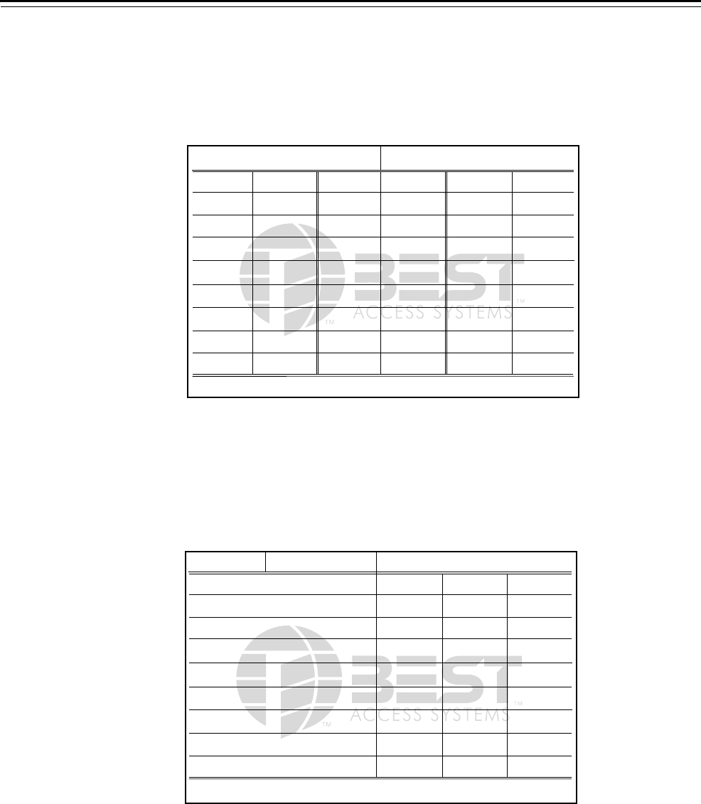
G-Series cards
and equipment
The following cards and equipment are essential to implement a key
control program if you do not have the Keystone 600 software
program. Contact your local BEST Representative to obtain the G-Series
cards and equipment. Refer to the table below and the figures that
follow for descriptions of the listed G-Series products.
Card Description Figure No.
G-10 Door Number card Figure 6.1
G-11 CoreNumber card Figure 6.2
G-12 Key Marking card Figure 6.3
G-13 Employee Name card Figure 6.4
G-271 Key Request card Figure 6.5
G-275 Key Receipt card Figure 6.6
G-274 Lock Request card Figure 6.7
G-272 Safety Lock Opening Request card Figure 6.8
G-276 Lost Key Report card Figure 6.9
G-21 Key envelope Figure 6.10
G-20 Core envelope Figure 6.11
G-30 Key Return tag Figure 6.12
Service and Maintenance
A2 System Service Manual 6–7
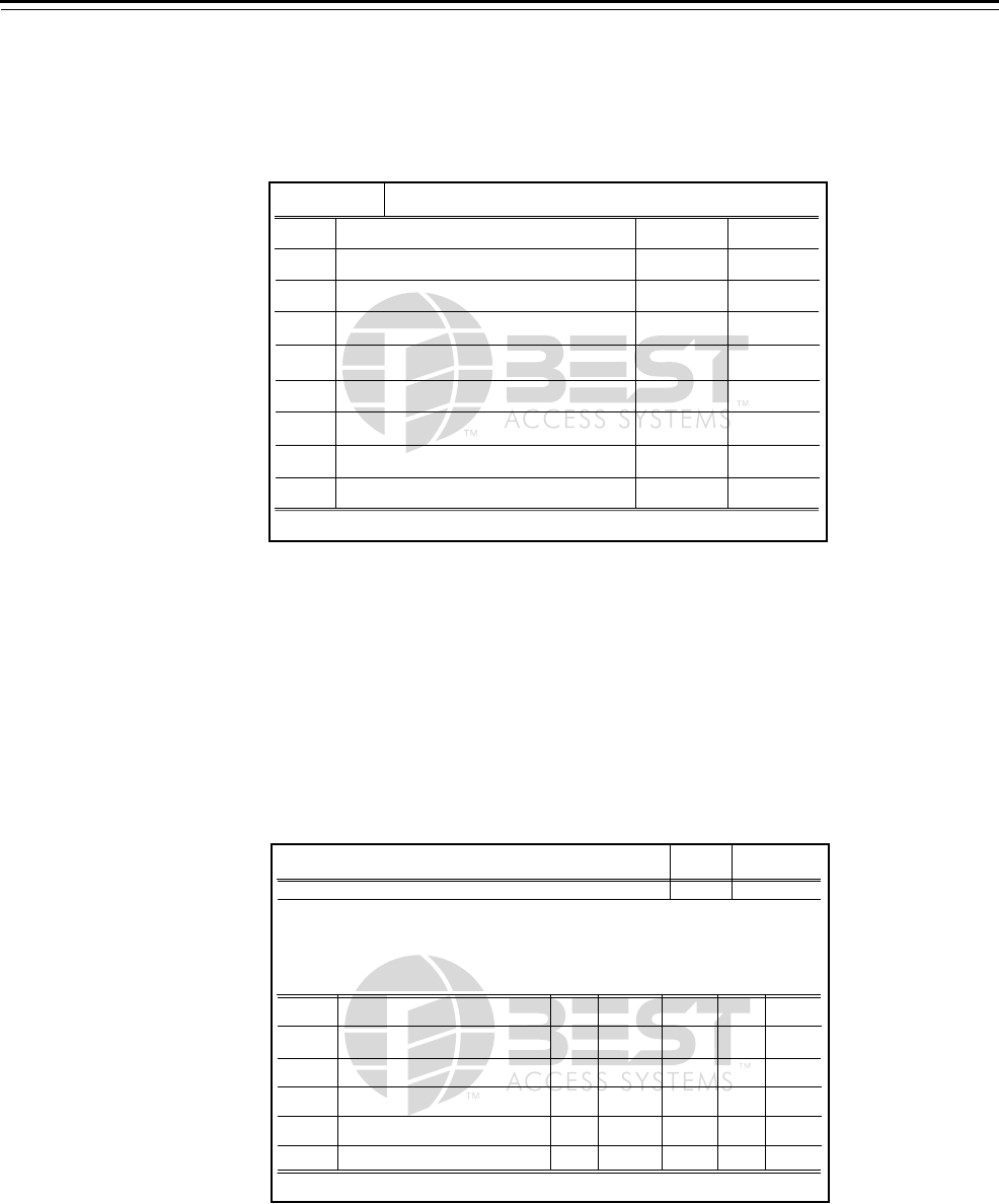
Door Number card
This card records specific information about the doors in a particular
building, such as door numbers, door locations, what core is installed,
as well as other pertinent data.
Core Number card
This card records where specific cores are located in a facility, and also
installation and removal dates.
Figure 6.1 Door Number card
KEY CONTROL
Printed in USA
DOOR NUMBER or Alphabetical Location
CORE
NUMBER DATE
INSTALLED CORE
NUMBER DATE
INSTALLED CORE
NUMBER DATE
INSTALLED
BEST ACCESS SYSTEMS
INDIANAPOLIS, IN 46250 G-10
1359050
Figure 6.2 Core Number card
KEY CONTROL
Printed in USA
CORE NUMBER
DOOR
NUMBER DATE
INSTALLED DATE
REMOVED
LOCATION OF CORE
BEST ACCESS SYSTEMS
INDIANAPOLIS, IN 46250 G-11
1284510
Service and Maintenance
6–8 A2 System Service Manual
Key Marking card
This card records all personnel carrying a specific key. It also indicates
when that key was issued and returned.
Employee Name card
This card records individual employee information. It also identifies
keys that the individual carries and serves as a signed acknowledgement
of internal policy and procedures. The agreement section is left blank
so that you can write or stamp your company’s key agreement
statement. For sample key agreements, see page 6–13.
Figure 6.3 Key Marking card
KEY CONTROL
Printed in USA
BEST ACCESS SYSTEMS
INDIANAPOLIS, IN 46250 G-12
KEY NUMBER
DATE
ISSUED DATE
RETURNED
NAME OF KEY HOLDER
Individual
Key ID
1284551
Figure 6.4 Employee Name card
Last Name First Name Middle In. Locker # Clock #
Agreement:
Key
Number Signature Date
Issued
Date
Issued
Date
Issued
Issued by Remarks
KEY CONTROL
Printed in USA
BEST ACCESS SYSTEMS
INDIANAPOLIS, IN 46250 G-13
1284593

Service and Maintenance
A2 System Service Manual 6–9
Key Request card
This card is used to request a key to be issued to employees for defined
areas and requires an employee signature and date.
Key Receipt card
This card records the name of the employee who has returned a key.
Figure 6.5 Key Request card
KEY CONTROL
Printed in USA
BEST ACCESS SYSTEMS
INDIANAPOLIS, IN 46250 G-271
1358979
Last Name First Name Middle In.
I request that the above person be issued a key
To KEY CONTROL DEPARTMENT:
to open
Signed Position Date
Approved by Position Date
KEY REQUEST
Figure 6.6 Key Receipt card
KEY CONTROL
Printed in USA
BEST ACCESS SYSTEMS
INDIANAPOLIS, IN 46250 G-275
1359176
Has received from
To KEY CONTROL DEPARTMENT:
Key number
Signed Position Date
KEY RECEIPT

Service and Maintenance
6–10 A2 System Service Manual
Lock Request card
This card is used to request that lock changes or additions take place.
Safety Lock Opening Request card
This card is used to authorize key control personnel to open a
designated lock for a particular person.
Figure 6.7 Lock Request card
KEY CONTROL
Printed in USA
BEST ACCESS SYSTEMS
INDIANAPOLIS, IN 46250 G-274
1359129
Last Name First Name Middle In.
the above named person requests the following
To KEY CONTROL DEPARTMENT:
lock changes or additions be made
Reason for making the change
Signed Position Date
Approved by Position Date
LOCK REQUEST
Figure 6.8 Safety Lock Opening Request card
KEY CONTROL
Printed in USA
BEST ACCESS SYSTEMS
INDIANAPOLIS, IN 46250 G-273
1359019
Last Name First Name Middle In.
You are authorized to open the SAFETY LOCK
To KEY CONTROL DEPARTMENT:
belonging to the above named person
Signed Position Date
Approved by Position Date
SAFETY LOCK
OPENING REQUEST
Service and Maintenance
A2 System Service Manual 6–11
Lost Key Report card
This card is used to report when a key has been lost or stolen. The
circumstances of the missing key can be listed here to give to the key
control department.
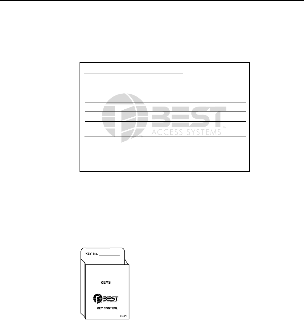
Key envelope
One envelope is used per spare key and can be filed numerically
according to key markings. Keep all envelopes containing spare keys in
a secure location.
Figure 6.9 Lost Key Report card
KEY CONTROL
Printed in USA
BEST ACCESS SYSTEMS
INDIANAPOLIS, IN 46250 G-276
1359815
Last Name First Name Middle In.
This is to report that the above named person has
To KEY CONTROL DEPARTMENT:
lost his or her key on
and requests that a replacement key be issued.
under the following circumstances
Signed Position Date
Approved by Position Date
LOST KEY REPORT
Figure 6.10 Key envelope
Service and Maintenance
6–12 A2 System Service Manual
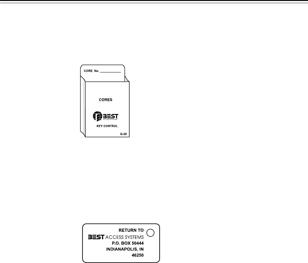
Core envelope
One envelope is used per spare core and can be filed numerically
according to core markings. Keep all envelopes containing cores in a
secure location.
Key Return tag
The tag is labeled with the BEST address on the front and a number that
identifies the employee who uses a particular key on the back. If this
tag is found with a key, the key can be returned to BEST postage paid so
that the finder cannot trace the key’s origin.
Figure 6.11 Core envelope
Figure 6.12 Key Return tag

Service and Maintenance
A2 System Service Manual 6–13
Procedures to
administer your
key control
system
The following actions are necessary to implement an effective key
control program (adapt the following as needed for your facility).
■Obtain the appropriate cards and storage equipment, either by
purchase from BEST or through local design.
■Inventory all locks throughout the facility that are in use, or should
be used and list these locks by door number on a Door Number card.
See Figure 6.1 on page 6–7.
■Inventory all BEST cores in use at the facility and list the core
numbers on the Core Number cards. See Figure 6.2 on page 6–7.
■Inventory all keys that have been issued for the various locks, as well
as spare keys on hand, and list them on the Key Marking card. See
Figure 6.3 on page 6–8.
■Compile a listing of all individuals holding keys to the building.
Review this list thoroughly and reduce the number of key holders to
an absolute minimum.
■Use the Employee Name card to record what keys are held by each
employee with each of their signatures. See Figure 6.4 on page 6–8.
■Store all key record cards in a lockable container, using dividers
when needed.
■Store all unused keys and cores for future use:
▲Place each spare key and spare core in the appropriate envelopes.
▲Identify the key/core on the outside of the envelope.
▲Store all envelopes in a lockable container.
Sample key
agreements
The Employee Name card (see Figure 6.4 on page 6–8) includes a blank
section for written agreements that employees must agree to before
receiving a key. For ideas of what might be printed in the “Agreement”
section of an Employee Name card, see the examples listed below:
■I, the undersigned, hereby acknowledge receipt of the key/s
described below. I promise and agree not to duplicate or have
duplicated the key/s issued to me and to return it/them to the
issuing office upon demand or when my need for said key/s no
longer exists. I further agree that if said key/s is/are lost or otherwise
not available for return, I will pay to the issuing office the sum of __.
■I, the undersigned, hereby acknowledge receipt of the key/s
described below, with the understanding that if I attempt to make
duplicates, or loan this/these key/s to any other person, I, herewith,
present myself to receive whatever punishment or disciplinary
action the administration of this institution deems reasonable and
just.
■I, the undersigned, by accepting the identified key/s, hereby agree to
take diligent care and promptly report any loss thereof. I further
agree to not give possession of said key/s to any other person nor
cause or allow any copies to be made of such key. I understand that
any violation of this agreement may result in termination of my
employment with_____________.

Service and Maintenance
6–14 A2 System Service Manual
Issuing and
returning keys
To issue a new key:
1. The employee submits a Key Request card. See Figure 6.5 on
page 6–9.
2. Fill out an Employee Name card and file this alphabetically. See
Figure 6.4 on page 6–8.
3. On a Key Marking card, indicate the following (see Figure 6.3 on
page 6–8):
■key number
■employee’s name
■date the key is issued.
4. The employee signs the Employee Name card which becomes, in
effect, a contract.
When a key is returned:
1. Fill out a Key Receipt card and make a copy for your records. See
Figure 6.6 on page 6–9.
2. Give the original copy to the employee in exchange for the key.
3. On the appropriate Key Marking card, strike out the employee’s
name and indicate the date that the key is returned. See Figure 6.3
on page 6–8.
4. On the appropriate Employee Name card , do the following (see
Figure 6.4 on page 6–8):
■strike out the “key number” line
■initial your changes and record the date
■place this card in the inactive file if no other keys are currently
signed out by this employee.
5. File the Key Receipt card copy.
Tips for managing your keys
■Send a test key to the factory or to your BEST Representative
periodically for inspection.
■Destroy returned or worn keys but do not throw them in the trash.
■Replace master keys annually.
■Do not keep a file of your key cuts.
■Keep your control key in a secure location. Do not carry one with
you.

Service and Maintenance
A2 System Service Manual 6–15
When keys are
lost or stolen
Guidelines for dealing with lost/stolen keys
It is important to be prepared when keys are lost or stolen. Follow the
guidelines below.
■Establish a policy that requires employees to report missing keys
immediately in person or by phone.
■Obtain BEST key trap cores for emergencies (see page 4–3).
■Attach Key Return tags to keys distributed to employees (see
page 6–12).
Reporting lost or stolen keys
If an employee has lost a key or has had a key stolen from them,
perform the following steps.
1. On a Lost Key Report card, record the employee’s name and the
date that the key was lost for the key control department. See
Figure 6.9 on page 6–11.
2. Determine the security need for a relock (see page 5–9) or for
installing a key trap core at the lost key location.
3. Take proper disciplinary actions against the appropriate employee if
necessary and record proceedings.
4. On a Key Request card, record the employee’s name and the date of
the request for the key control department. See Figure 6.5 on
page 6–9.
Adding,
removing and
changing cores
To add a new core:
1. Enter the door number at the top of a new Door Number card. See
Figure 6.1 on page 6–7.
2. Enter the core number and date of installation.
3. Find the appropriate Core Number card (or start a new card if a new
core number is used) and add the location of the newly installed
core. See Figure 6.2 on page 6–7.
To remove a core:
1. Find the appropriate Door Number card and strike off the core
number and date. See Figure 6.1 on page 6–7.
2. Enter “none” under “Core No.” and specify the date of removal.
3. Find the appropriate Core Number card and strike out the line for
core location. See Figure 6.1 on page 6–7.

Service and Maintenance
6–16 A2 System Service Manual
To change a core:
1. Find the appropriate Door Number card and strike out the old core
number and date. See Figure 6.1 on page 6–7.
2. Enter the new core number and date of installation.
3. Find the Core Number card that has the new core number and enter
the following (see Figure 6.2 on page 6–7):
■location
■date
■door number.
4. Find the Core Number card for the old core. Strike out the entry
name and then record the date of removal.
Tips for managing your cores
■Destroy all worn cores but do not throw them in the trash.
■Do not leave any barrels empty when loading the core.
■Do not keep a file of your pin segment order for combinating cores.
Planning for
emergencies
Setting aside extra codes
It is important to have extra codes set aside in the event that you need
to change several or all of the locks in a particular area of your facility.
For instance, if an employee’s master key is lost or stolen, then the
cores for the locks that the key has access to need to be recombinated
or replaced.
Having precombinated cores available
In the event of an emergency where you need to replace a core, you
may want to have precombinated cores at your disposal for a quick and
efficient changeover. You may need to replace only one particular core,
but it is possible that you will need to replace several cores at once
(page 5–9).
Emergency blockout blade
If no other measures can be taken, you can insert a keyway blockout
blade into a core to prevent unauthorized entry (page 4–3). The
blockout blade requires a special tool to remove it from the core.
Contact your BEST Representative to order blockout blades and the
removal tool.

Service and Maintenance
A2 System Service Manual 6–17
PARTS SERVICING
For parts servicing, refer to the following manuals for your specific
needs.
GENERAL CORE MAINTENANCE
It is necessary to periodically clean and inspect your cores to ensure
that they are functioning properly. Perform the following tasks as
needed:
■Check for proper installation of any new cores
■Conduct periodic checks of the cores
▲operation of core in lockset
▲determine general wear
▲schedule a preventive maintenance plan
■Service and replace parts
■Lubricate cores according to your maintenance plan.
Instructions for Refer to
Replacing a dust cover assembly
Lubricating a core
Thawing a core
Cleaning a core
Core and Key Service Manual (T35527)
Replacing components on the key
combinator:
■punch and die
■key carriage
■operating lever
Adjusting the key clamp spring
Calibrating the key combinator
Cleaning the key combinator
Lubricating the key combinator
Key Combinator Service Manual (T35532)

Service and Maintenance
6–18 A2 System Service Manual

A2 System Service Manual A–1
AGLOSSARY
Calibrate To check against a known standard and adjust to that
standard.
Cap Small piece of brass that is seated within a barrel, just
below the surface of a core, to contain the segments
and springs in each barrel.
Capping block Small steel block used to hold a core while a cap is
being seated within a barrel of the core.
Code A number that specifies the cuts of a key that will
properly operate a core (also relates to the
combination of a core).
Combinating Selecting a core’s pin segments to match the key
cuts.
Control key A high-security key—unique for each BEST system—
designed to remove and insert the figure-8 core.
Coremark Sequence of letters and/or numbers that identifies a
particular core.
Depth selector Dial on a key combinator, marked with numbers,
that is used for selecting key cut depths.
Ejector pin Tool used to remove pin segments, springs, and caps
from a core one barrel at a time.
Grandmaster key Key that normally operates all locks in a masterkey
system. However, a masterkey system might be
designed so that the grandmaster key cannot operate
selected locks such as cash boxes, hazardous waste
areas, or drug cabinets.
Hand capping pin Pin used to seat the cap within a barrel of a core.

Glossary
A–2 A2 System Service Manual
Interchangeable
core
Figure-8 shaped device that contains the main parts of a masterkey
system. The interchangeable core can be removed by a special control
key and can be recombinated without disassembling the lock.
Key agreement Document describing rules for a key issued to an employee and often
signed by the employee. A key agreement might indicate how the
employee should treat the key, when the key must be returned, and
what the employee should do if the key is lost or stolen.
Key blade Portion of a key that contains the keyway milling and key cuts.
Key blank Key that has no key cuts.
Key carriage Housing on a key combinator that moves the key to each keycut
position.
Key combinator Machine that cuts BEST key blanks for BEST masterkey systems.
Keycut depth The distance from the bottom of the key cut to the underside of the key
blade.
Keymark Sequence of letters and numbers that indirectly corresponds to a keycut
pattern for a key or group of keys that operates a particular core or
lock.
Keystamp Code number indicating the words stamped on all keys in a particular
masterkey system. For example, “DO NOT DUPLICATE” or a company
name can be keystamps.
Keyway Cross-section shape milled into the key blank and broached into core
plugs.
Keyway milling Grooves machined into the length of the key blade to allow entry into
the opening of a core.
Loading a core Process of inserting segments, springs, and caps into each barrel of a
core according to predetermined specifications.
Master key Key that operates a large group of cores or locks, such as all locks in a
building, on a floor, or for a department.
Masterkeying Process of combinating locks to allow a single key to operate many
locks and at the same time allow each lock to be operated by a unique
key.
Masterkey system A complete hierarchical system provided by BEST Access Systems. A
system normally consists of keymarks and coremarks that lets a single
key operate many cores, and also lets each core be operated by its own
key.
Multi-milling Milling of a key to pass more than one keyway.
Operating key Key that operates only one core or one group of keyed alike cores in a
keying system.
Pin segment Cylindrical-shaped part that fits into all barrels of a core. The sequence
of pin segments varying in length inside a core permits a key to operate
the core.

Glossary
A2 System Service Manual A–3
Punch and die Part of the key combinator that notches keys to a precise shape.
Registered codes Customized security codes assigned to a BEST Masterkey System. Only
authorized personnel may receive these codes by registered mail.
Service equipment Devices that allow a company to maintain and repair their own BEST
Locking System. Service equipment includes key combinators, capping
presses, and so forth.
Submaster key Key that can unlock only specified groups of locks within a system.

Glossary
A–4 A2 System Service Manual

A2 System Service Manual B-1
BINDEX
A
assessing an existing system 5–2
B
benefits of BEST masterkey system 2–2
C
capping block 3–4
cards
see key control system
code records 2–9
codes
obtaining 5–7
overview of 2–8
updating records for 6–5
combinating bin 3–4
combinating cores 6–2
combinating hammer 3–4
combinating kit 3–4
control key 2–6
core capping press 3–4
core dust cover 4–3
core envelope 6–12
core marking block 3–5
core marking plate 3–5
Core Number card 6–7
core stamping plate 3–5
cores
adding 6–15
changing 6–16
combinating 6–2
control of 2–10
installing 6–4
lubricating 3–5
options 4–3
overview of 2–6, 3–2
removing 6–15
servicing 6–17
stamping 6–3
tools for servicing 3–4
tools for stamping 3–5
cutting keys 6–3
D
designing a masterkey system 2–4
documentation package 1–2
Door Number card 6–7
drill resistant cores 4–3
E
ejector pin 3–4
emergencies 6–16
Employee Name card 6–8
extractor key 3–4
F
forms
see key control system
G
grandmaster key 2–6
graphite gun 3–5
G-Series forms 2–10
H
hand capping pin 3–4

Index
B-2 A2 System Service Manual
I
installing cores 6–4
K
key combinator 3–4
key control system
administering 6–13
cards and equipment 6–6
developing 6–5
sample key agreements 6–13
key cut indicator 3–4
key envelope 6–11
key marking block 3–5
Key Marking card 6–8
key marking plate 3–5
Key Receipt card 6–9
Key Request card 6–9
key return tag 6–12
key stamping plate 3–5
keying schematic 5–4
keys
control of 2–10
control system for 6–5
cutting 6–3
issuing 6–14
overview of 2–6, 3–3
returning 6–14
stamping 6–3
tools for servicing 3–4
tools for stamping 3–5
types 2–6
updating records for 6–5
Keystone 600 2–10, 6–6
keytrap core 4–3
keyway blockout blade 3–4, 4–3,
6–16
keyways 2–7, 4–2
L
letter dies 3–5
Lock Request card 6–10
Lost Key Report card 6–11
LPS lubricant 3–5
lubricating cores 3–5
M
magnetic strip 3–5
master key 2–6
masterkey system
assessing changes to 5–2
BEST benefits 2–2
designing 2–4
determining size 2–8
heirarchy of 2–7
overview of 2–4
planning for emergencies 6–16
security for 2–9
N
number dies 3–5
O
operating key 2–6
P
patented keyways 2–7, 4–2
pick and drill resistant cores 4–3
pick resistant cores 4–3
pin size 2–8
product family diagram 2–5
R
re-locks 5–9
restricted keyways 2–7, 4–2
S
Safety Lock Opening Request card
6–10
schematic
see keying schematic
scrambled codes 4–3
security 2–9
site survey 5–2
stamping cores and keys 6–3
stamping tools 3–5
standard keyways 2–7, 4–2
submaster key 2–6
support, technical 1–2
survey
see site survey
T
technical documentation package
1–2
technical support 1–2
tools
for servicing cores and keys
3–4
for stamping 3–5
lubrication items 3–5
tweezers 3–4
W
warranty 2–3
wear resistant cores 4–3
