BEST Key Combinator Service Manual T61804
User Manual: BEST Key Combinator Service Manual Service Manual
Open the PDF directly: View PDF ![]() .
.
Page Count: 54
- Contents
- Figures
- 1 Getting Started
- 2 Parts
- 3 Service and Maintenance
- A Glossary
- B Preventative Maintenance
- C Index

SERVICE MANUAL
SERVICE MANUAL
CREDITS/COPYRIGHT
©2001 Best Lock Corporation dba Best Access Systems. All rights reserved. Printed in
the United States of America.
Information in this document is subject to change without notice and does not
represent a commitment on the part of Best Access Systems. The software described in
this document are furnished under a license agreement or nondisclosure agreement.
This publication is intended to be an accurate description and set of instructions
pertaining to its subject matter. However, as with any publication of this complexity,
errors or omissions are possible. Please call your BEST distributor or Best Access
Systems at (317) 849-2250 if you see any errors or have any questions. No part of this
manual and/or databases may be reproduced or transmitted in any form or by any
means, electronic or mechanical, including photocopying, recording, or information
storage and retrieval systems, for any purpose, without the express written permission
of Best Access Systems.
This document is distributed as is, without warranty of any kind, either express or
implied, respecting the contents of this book, including but not limited to implied
warranties for the publication’s quality, performance, merchantability, or fitness for any
particular purpose. Neither Best Access Systems, nor its dealers or distributors shall be
liable to the user or any other person or entity with respect to any liability, loss, or
damage caused or alleged to be caused directly or indirectly by this publication.
The Life Safety Code is a registered trademark of the National Fire Protection
Association.
Written and designed by Best Access Systems and Avalon Group, Inc., Indianapolis,
Indiana.
T61804 Rev – 1837172 ER7991-6 October 2001

Key Combinator Service Manual iii
CONTENTS
FIGURES V
GETTING STARTED 1–1
Introduction 1–1
Product family diagram 1–2
Documentation package 1–3
Technical support 1–3
Support services 1–3
Telephone and web technical support 1–3
Training seminars 1–3
PARTS 2–1
Exploded diagram of a key combinator—left hand 2–2
Exploded diagram of a key combinator—right hand 2–3
Key options 2–4
Standard key 2–4
Premium key 2–4
Patented key 2–4
Keyway options 2–5

Contents
iv Key Combinator Service Manual
SERVICE AND MAINTENANCE 3–1
Combinator handing 3–2
Left-handed vs. right-handed combinators 3–2
Maintenance tools 3–2
BEST tools 3–2
Additional tools 3–3
Cutting keys 3–4
Loading the key 3–4
Cutting the key 3–5
Unloading the key 3–6
Converting the combinator between the A2, A3, and A4 systems 3–7
Replacing the depth selector 3–7
Replacing parts 3–9
Replacing the punch and die 3–9
Replacing the key carriage 3–11
Replacing the operating lever 3–13
Calibrating the key combinator 3–16
Cutting a calibration key 3–16
Placing the key in the gauge 3–18
Reading the gauge 3–18
Totaling the measurement 3–19
Checking the measurement 3–19
Adjusting the depth selector 3–20
Adjusting the key clamp spring 3–25
Preventative maintenance 3–27
Cleaning parts 3–27
Cleaning the punch and die 3–27
Cleaning the key carriage 3–27
Lubricating parts 3–28
Guidelines for lubrication 3–28
Lubricating the key combinator housing 3–28
Troubleshooting 3–31
GLOSSARY A–1
PREVENTATIVE MAINTENANCE B–1
INDEX C–1

Key Combinator Service Manual v
FIGURES
GETTING STARTED
Key combinator product family 1–2
PARTS
LH key combinator 2–2
RH key combinator 2–3
Standard key blank 2–4
Premium key blank 2–4
Patented key blank 2–4
SERVICE AND MAINTENANCE
BEST maintenance tools 3–2
Loading a key 3–4
Key in the key clamp spring 3–5
Cutting a key 3–6
Removing the depth selector 3–7
Reinstalling the depth selector 3–8
Punch and die assembly 3–9
Inserting the punch into the T-slot 3–10
Removing the key carriage 3–11
Reinstalling the key carriage 3–12
Depressing the key carriage plungers 3–13
Removing the operating lever 3–14
Reinstalling the operating lever 3–15
Cutting a calibration key 3–17

Figures
vi Key Combinator Service Manual
Inserting a key into the key gauge 3–18
Calibration measurement scale 3–19
Marking the depth selector assembly 3–20
Loosening the spanner nut 3–21
Turning the depth adjuster counterclockwise 3–22
Turning the depth adjuster clockwise 3–23
Loading a key 3–25
Adjusting the key clamp spring 3–26
Lubricating parts 3–29
Lubricating the punch and die 3–30

Key Combinator Service Manual 1–1
1GETTING STARTED
INTRODUCTION
The Key Combinator Service Manual contains
essential information to help you maintain your BEST
key combinator.
Getting Started
1–2 Key Combinator Service Manual
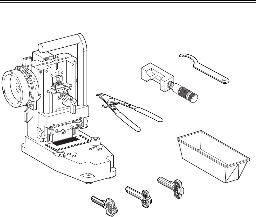
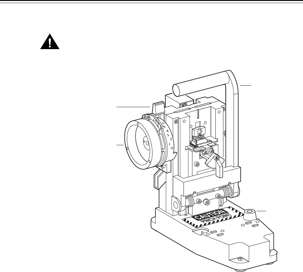
PRODUCT FAMILY DIAGRAM
Figure 1.1 Key combinator product family
CAUTION
PINCH POINT
ALIBRATE
YSTEM A2
Patented key blank
Premium key blank
Standard key blank
Spanner wrench
Calibration gauge
Key combinator
Chip tray
Circlip pliers

Getting Started
Key Combinator Service Manual 1–3
DOCUMENTATION PACKAGE
The following documentation is available to help you with the
installation, operation, and maintenance of your BEST key combinator
along with associated service equipment. These documents also can be
ordered separately from the product.
TECHNICAL SUPPORT
Support
services
When you have a problem with a BEST key combinator, your first
resource for help is the Key Combinator Service Manual. If you cannot
find a satisfactory answer, contact your local BEST Representative.
Telephone and
web technical
support
A factory-trained Certified Product Specialist (CPS) is available in your
area whenever you need help. Before you call, however, please make
sure that the product is in your immediate vicinity, and that you are
prepared to give the following information:
■what happened and what you were doing when the problem arose
■what you have done so far to correct the problem.
Best Access Systems Representatives provide telephone technical
support for key combinators and related products. You may locate the
representative nearest you by calling (317) 849-2250 Monday through
Friday, between 7:00 a.m. and 4:00 p.m. eastern standard time; or visit
the web page, www.BestAccess.com.
Training
seminars
Best Access Systems regularly holds factory training seminars for
owners of BEST masterkey systems. Your BEST Representative may hold
regular seminars as well. Contact your representative for information on
these seminar opportunities.
Document Title Doc. No.
Core and Key Service Manual T35527
Operating Instructions for AD432 Key Combinator T35531
Operating Instructions for AD433 Key Combinator T35529
Operating Instructions for AD502 Micrometer Key Gauge T35530

Getting Started
1–4 Key Combinator Service Manual

Key Combinator Service Manual 2–1
2 PARTS
The following pages contain descriptions and figures
for the key combinator.
Par
t
s
2–2 Key Combinator Service Manual
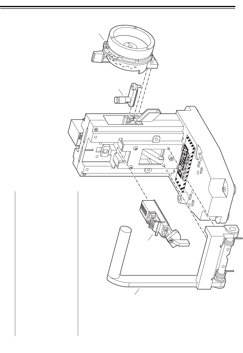
EXPLODED DIAGRAM OF A KEY COMBINATOR—LEFT HAND
Figure 2.1 LH key combinator
CALIBRAT
SYSTEM A
Item†Part No. Qty. Description
1 A70595 1 Operating lever assembly
2
not shown
not shown
C70580
C70610
C70601
1
1
1
Premium key carriage
Key carriage for BEST/Peaks—7-pin
Key carriage for BEST/Peaks—6-pin
3
not shown
B70341
B70625
1
1
Punch and die assembly
Punch and die assembly for BEST/Peaks
4
not shown
not shown
A70325
A70326
A70327
1
1
1
Depth selector assembly—A2
Depth selector assembly—A3
Depth selector assembly—A4
†See page 3–7 for instructions on converting between the A2, A3, and
A4 Systems.
1
2
3
4
Par
t
s
Key Combinator Service Manual 2–3
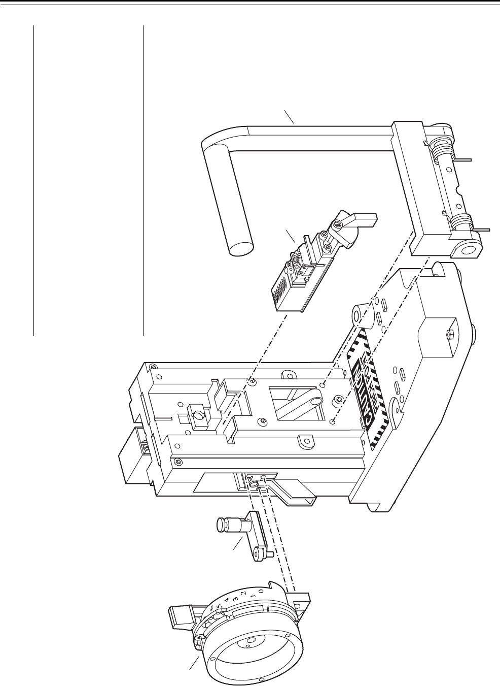
EXPLODED DIAGRAM OF A KEY COMBINATOR—RIGHT HAND
Figure 2.2 RH key combinator
ALIBRATE
YSTEM A2
Item†Part No. Qty. Description
1
not shown
not shown
C70322
C70323
C70324
1
1
1
Depth selector assembly—A2
Depth selector assembly—A3
Depth selector assembly—A4
2 B70341 1 Punch and die assembly
3
not shown
C70578
C70579
1
1
Standard key carriage
Premium key carriage
4 A70591 1 Operating lever assembly
†See page 3–7 for instructions on converting between the A2, A3, and
A4 Systems.
1
2
34
Parts
2–4 Key Combinator Service Manual
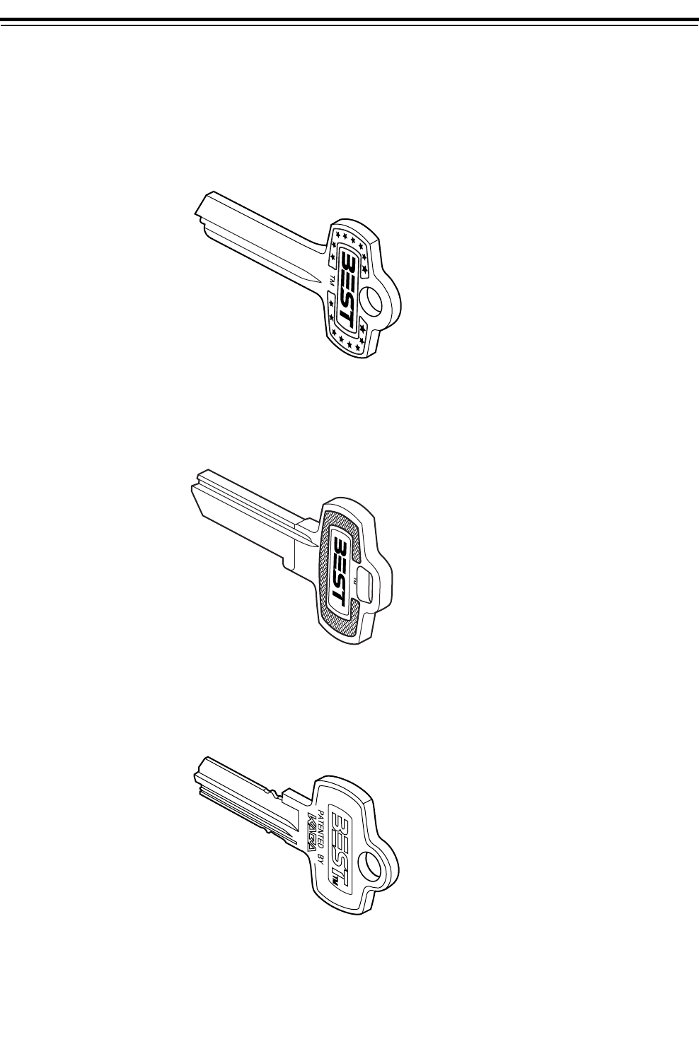
KEY OPTIONS
The following key options are offered by BEST. Refer to the Core and
Key Service Manual (T35527) for ordering information.
Standard key Standard keys are cut by the AD433 key combinator.
Premium key Premium keys are cut by the AD433P key combinator.
Patented key PEAKS patented keys are cut by the AD437 and AD436 key combinator.
Figure 2.3 Standard key blank
Figure 2.4 Premium key blank
Figure 2.5 Patented key blank

Parts
Key Combinator Service Manual 2–5
KEYWAY OPTIONS
The following section lists BEST keyways and the combinators that
must be used to cut the keys.
Note: BEST key combinators are available only to registered BEST
customers who currently have the A2, A3, or A4 masterkey system. For
more information, contact your local BEST Representative.
Standard keyways
All standard keyways require a RH configuration for the key
combinator.
Premium keyways
Some premium keyways require a LH configuration for the key
combinator and some require a RH configuration. See the table below.
Patented keyways
All patented keyways require a LH configuration. The B1 and B2
keyways are the only Peaks keyways available to use with the AD437
and AD436 key combinators.
Configuration Keyway
RH WA
WB
WC
WG
WH
WK
WY
LH WD
WE

Parts
2–6 Key Combinator Service Manual

Key Combinator Service Manual 3–1
3 SERVICE AND MAINTENANCE
This chapter contains instructions for servicing and
maintaining key combinator components, and a
section for troubleshooting common problems.
To
See
page
Understand combinator handing 3–2
Look at maintenance tools 3–2
Cut keys 3–4
Convert your combinator between A2,
A3, and A4 systems
3–7
Replace the punch and die 3–9
Replace the key carriage 3–11
Replace the operating lever 3–13
Calibrate the key combinator 3–16
Adjust the key clamp spring 3–25
Create a preventative maintenance plan 3–27
Clean the punch and die 3–27
Clean the key carriage 3–27
Lubricate parts 3–28
Troubleshoot common problems 3–31
Service and Maintenance
3–2 Key Combinator Service Manual
COMBINATOR HANDING
Left-handed vs.
right-handed
combinators
The terms “left-handed” and “right-handed” describe the handing of a
combinator, but this is not a convenience feature for left-handed or
right-handed individuals. The handing on a combinator is distinguished
by the position of its operating lever. The operating lever position
determines which types of keys the combinator can cut.
Left-handed key combinator
When facing the combinator, the operating handle is attached to the
left side of the left-handed or LH key combinator. A LH key combinator
cuts patented or left-handed premium keys. It does not cut standard
keys.
Right-handed key combinator
When facing the combinator, the operating handle is attached to the
right side of the right-handed or RH key combinator. A RH key
combinator cuts premium or right-handed standard keys. It does not cut
patented keys.
To determine which keys are appropriate for your security needs,
contact your BEST Representative. See page 2–5 for more information
on key combinators and their keyway types.
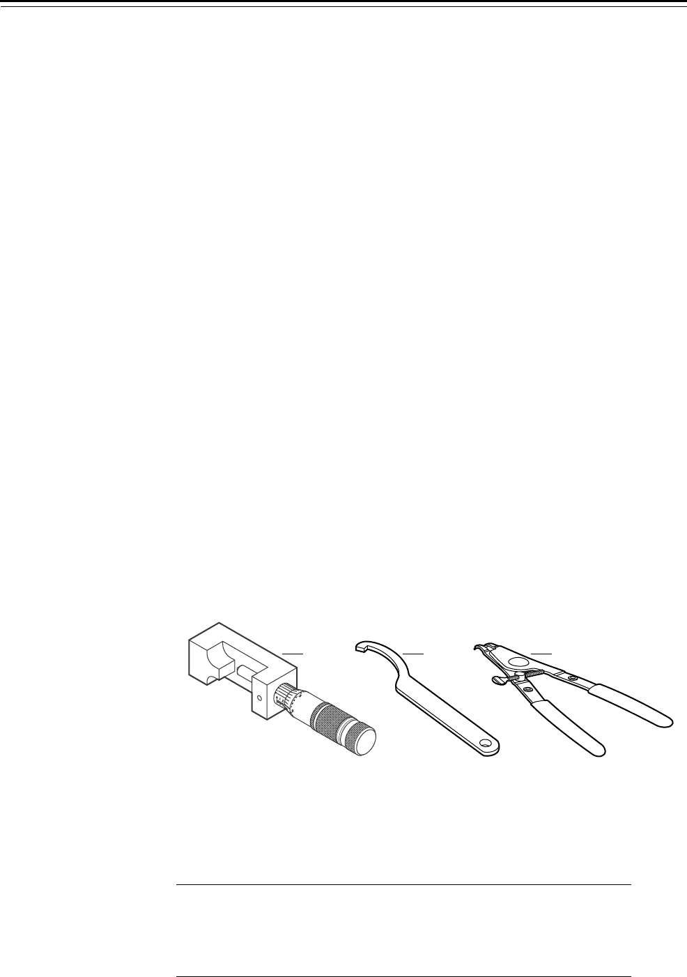
MAINTENANCE TOOLS
BEST tools The following tools are provided by BEST for servicing your key
combinator.
Maintenance tools parts list
Figure 3.1 BEST maintenance tools
12 3
Item
Nomen-
clature Part No. Qty. Description
1
not shown
AD502
AD502D
B70564
B70574
1
1
Key calibration gauge—standard
Key calibration gauge—digital
2 A70558 1 Spanner wrench
3 HT03009 1 Circlip pliers

Service and Maintenance
Key Combinator Service Manual 3–3
Additional tools The following Allen wrenches are used for servicing your key
combinator:
■3/32″
■7/64″
■1/8″
■9/64″
■5/32″
■3/16″.
Service and Maintenance
3–4 Key Combinator Service Manual
CUTTING KEYS
BEST recommends that you secure your key combinator to a flat surface
before you begin cutting keys. You can install bolts either through each
of the rubber feet or through two holes on the base of the combinator.
Contact BEST for further instructions.
Loading the key To load a BEST standard key blank:
1. Gripping the key clamp knob, pull the key carriage completely
forward.
2. Turn the key clamp knob counterclockwise to open the key clamp
spring (for left-handed combinators, turn the key clamp knob
clockwise). See Figure 3.2.
3. With the curved edge of the key blank against the locating surface,
slide the key blank into the key opening. Make sure that the knife
edge of the key clamp spring fits into the groove of the key. See
Figure 3.3.
Figure 3.2 Loading a key
ALIBRATE
YSTEM A2
Key
carriage
Key clamp
knob
Front view of combinator
Key opening
Locating surface
Service and Maintenance
Key Combinator Service Manual 3–5
4. Turn the key clamp knob clockwise, locking the key blank into the
key carriage (for left-handed combinators, turn the key clamp knob
counterclockwise).
The key clamp knob hangs loosely in the six o’clock position, as
shown in Figure 3.3
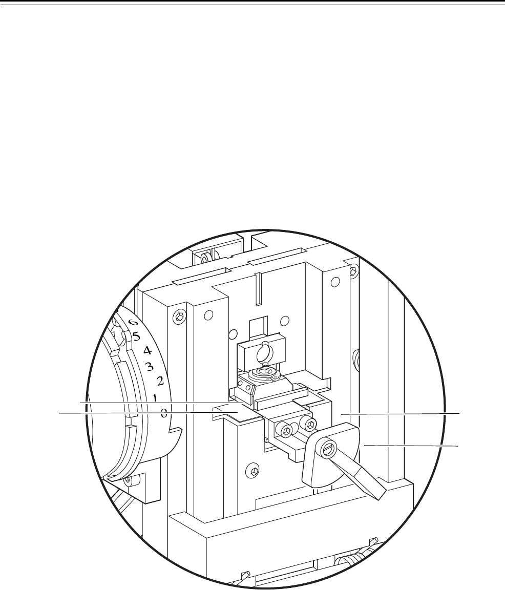
Cutting the key To cut a BEST standard key blank:
1. Before your begin to cut keys, make sure that the key carriage is still
completely forward.
2. Move the depth selector lever to the “0” mark for the setup stroke.
3. Pull the operating lever down firmly until it strikes the rubber
bumper; then, let the operating lever move back up.
Caution
Failure to strike the rubber bumper may cause the key carriage to
move to the next space too soon.
The combinator automatically moves the key carriage and key blank
into place for the first keycut.
Caution
Do not touch the key carriage during key cutting. The combinator
precisely advances the key carriage with each stroke of the operating
lever.
Figure 3.3 Key in the key clamp spring
ALIBRATE
YSTEM A2
Key carriage
Key clamp knob in
6 o’clock position
Key clamp spring
Front view of combinator
Groove of ke
y
Knife edge
Service and Maintenance
3–6 Key Combinator Service Manual
4. Move the depth selector dial to the keycut depth number that you
need for your key. See Figure 3.4.
Caution
Be sure to let go of the depth selector before making a cut. Any
pressure placed on the depth selector dial can cause the key to be cut
incorrectly.
5. Pull the operating lever down firmly until it strikes the rubber
bumper; then, let the operating lever move back up.
The combinator makes the first cut and automatically moves the key
carriage and key blank into place for the next cut.
6. Repeat Steps 3 and 4 until you have made all of the cuts on the key.
Unloading the
key
To unload a BEST standard key:
1. Gripping the key clamp knob, pull the key carriage completely
forward.
2. Turn the key clamp knob counterclockwise to open the key clamp
spring (for left-handed combinators, turn the key clamp knob
clockwise).
3. Slide the key out.
Figure 3.4 Cutting a key
ALIBRATE
YSTEM A2
Operating
lever
Rubber
bumper
Depth selector
assembly
Depth selector
dial
Service and Maintenance
Key Combinator Service Manual 3–7
CONVERTING THE COMBINATOR BETWEEN THE A2, A3, AND A4 SYSTEMS
The BEST AD433 key combinator gives you the ability to change from
one masterkey system to another by replacing the depth selector. For
example, you may want to change from an A2 System to an A4 System.
Replacing the
depth selector
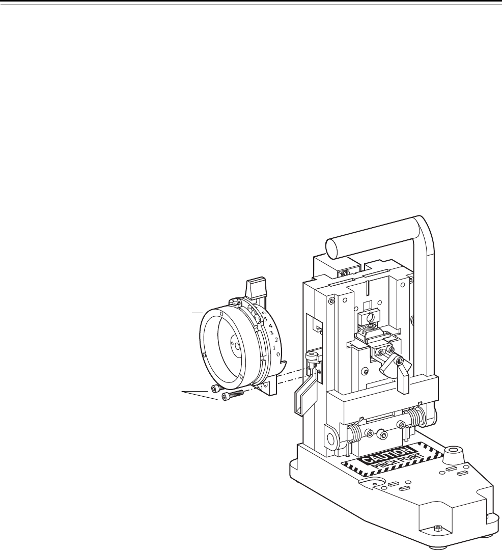
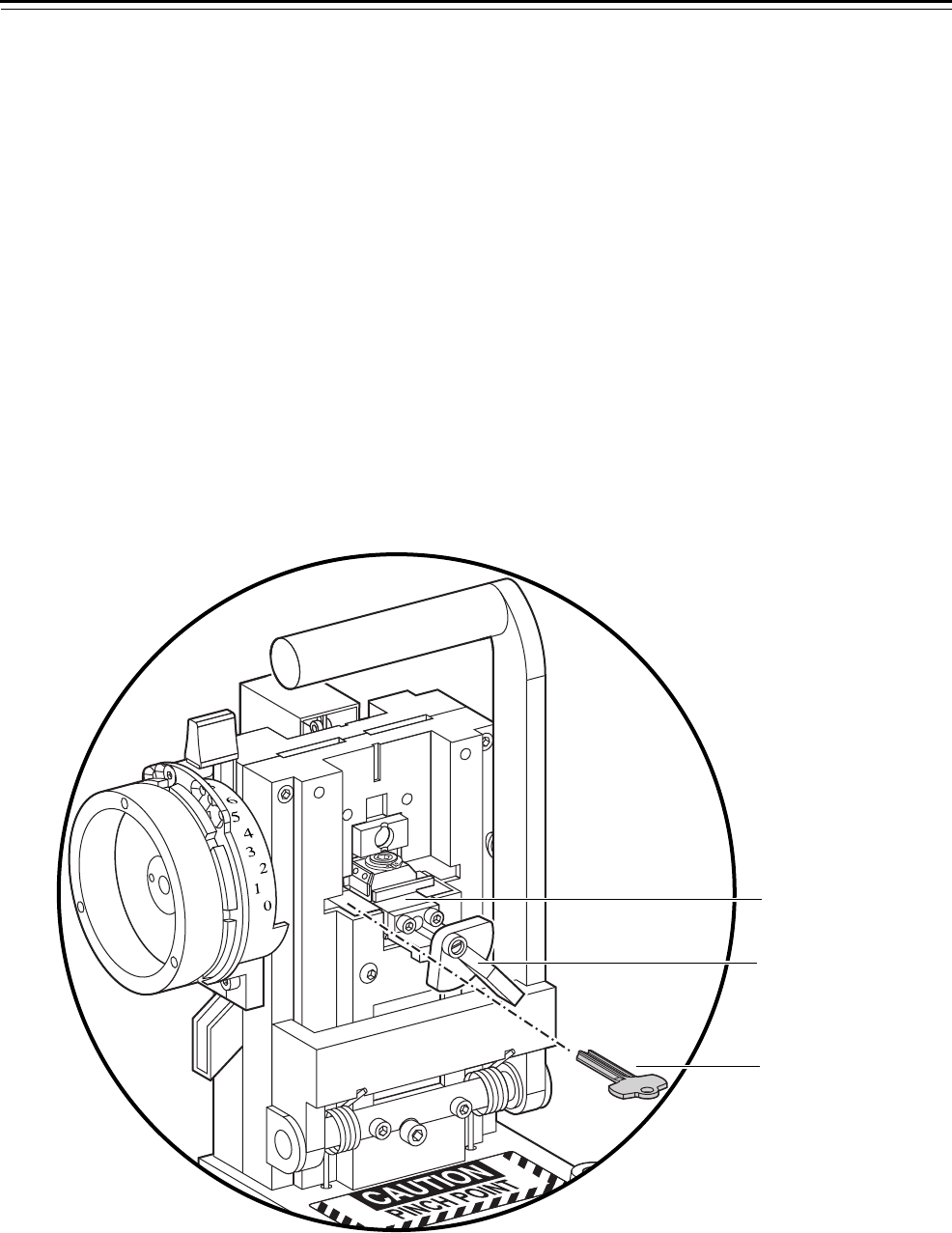
To remove the depth selector:
1. Using a 5/32″ Allen wrench, unscrew the two socket head machine
screws that secure the depth selector to the side of the combinator.
See Figure 3.5.
2. Remove the depth selector. Save the screws.
Figure 3.5 Removing the depth selector
ALIBRATE
YSTEM A2
S
ocket head
s
crews
Depth selector
assembly
Service and Maintenance
3–8 Key Combinator Service Manual
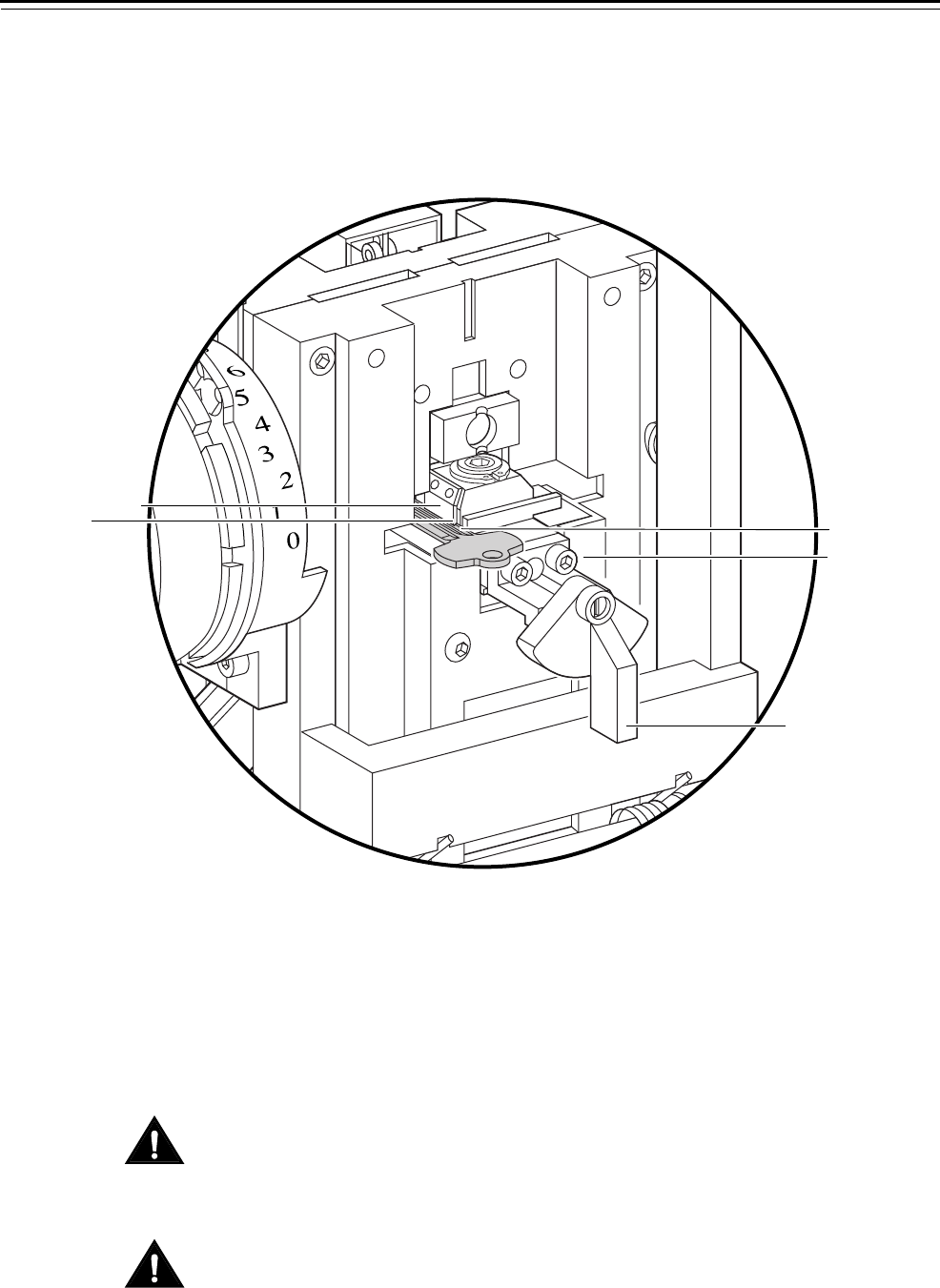
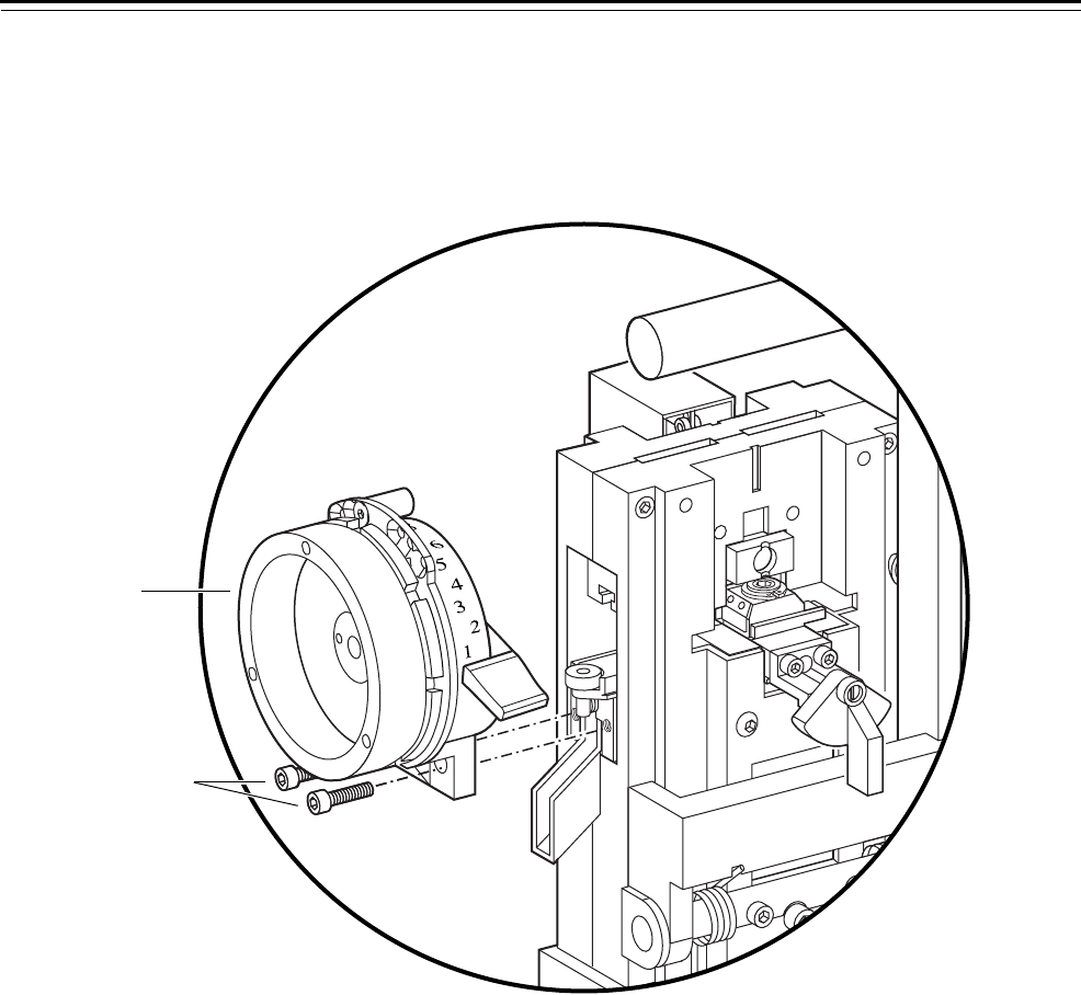
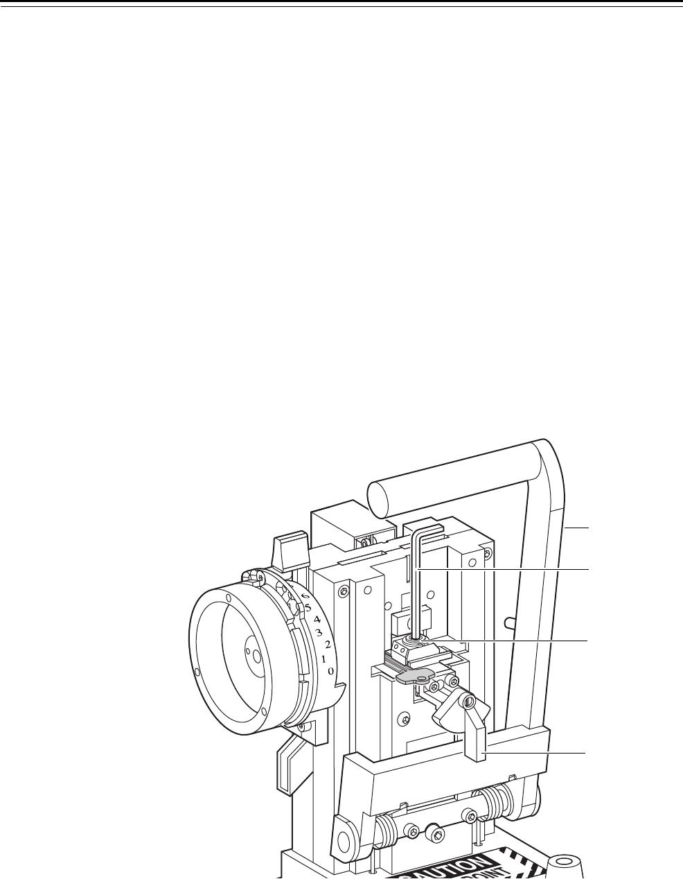
To reinstall the depth selector:
1. Turn the dial on the depth selector assembly to the “0” mark.
2. Align the two holes on the bottom of the depth selector assembly
with the threaded holes on the combinator. See Figure 3.6.
3. Insert two 5/32″ socket head machine screws through the holes and
tighten them with a 5/32″ Allen wrench.
4. Calibrate a key to make sure the new depth selector assembly is
properly installed (page 3–16).
Figure 3.6 Reinstalling the depth selector
ALIBRATE
YSTEM A2
Socket head screws
Depth selector
assembly
Service and Maintenance
Key Combinator Service Manual 3–9
REPLACING PARTS
Replacing the
punch and die
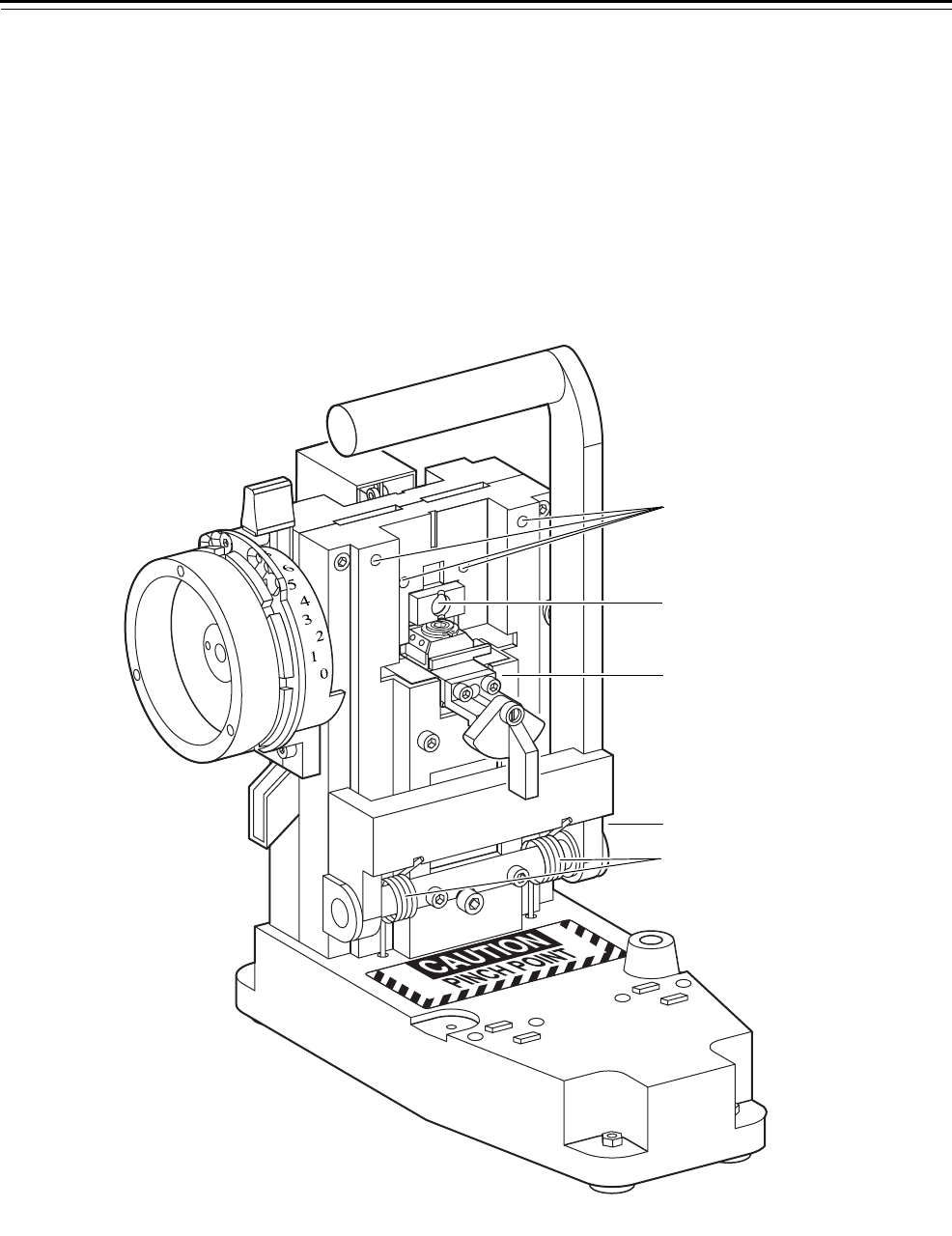
To remove the punch and die:
1. Make sure that the operating lever is in the upright position.
2. Remove the depth selector (page 3–7). Save all of the parts.
3. Remove the punch and die assembly. See Figure 3.7.
Note: The spring that sits below the punch and die assembly can pop
out during removal.
Figure 3.7 Punch and die assembly
Side view of combinator
Spring
Punch
Die assembly
Service and Maintenance
3–10 Key Combinator Service Manual
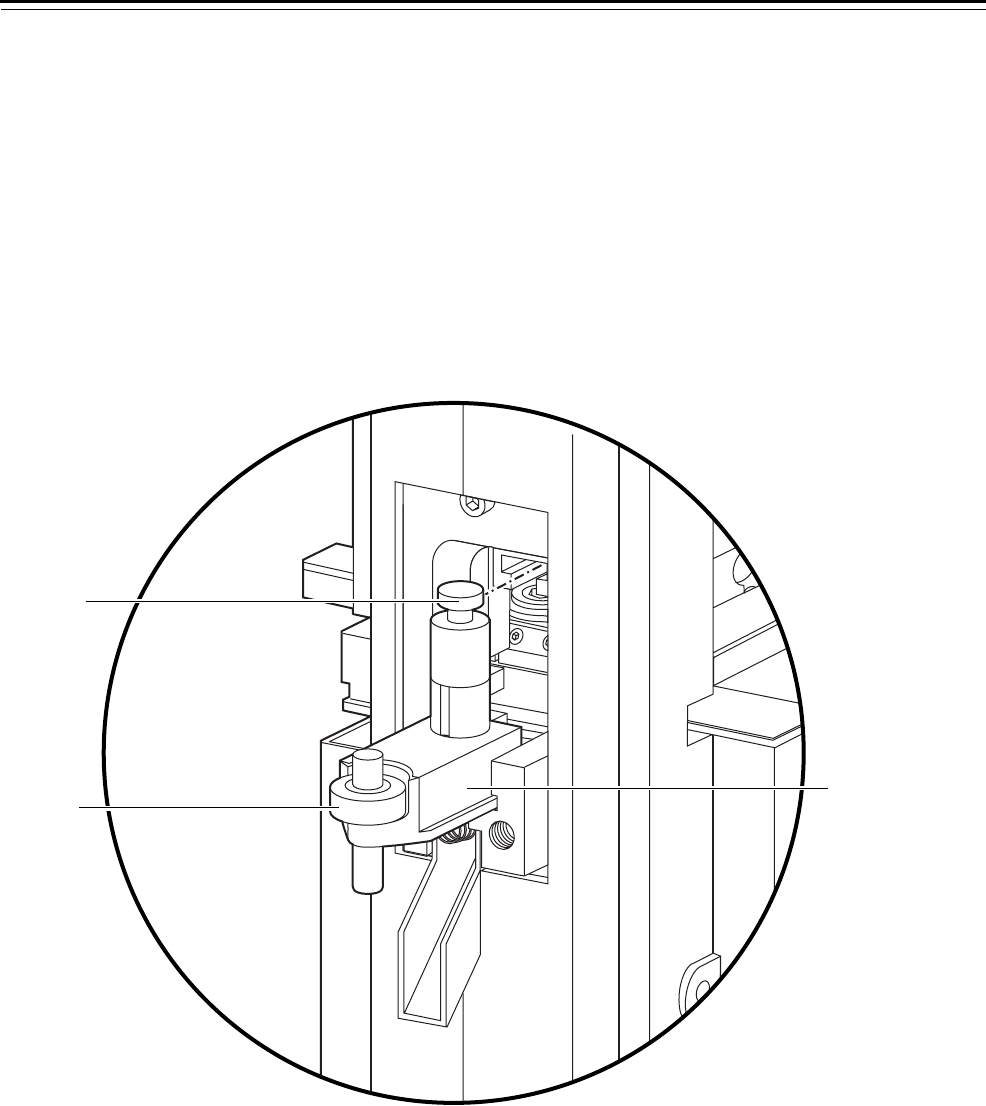
To reinstall the punch and die:
1. Make sure that the spring is resting in the space between the guide
rails.
2. Assemble the punch so that it sits in the die as shown in Figure 3.8.
3. Lightly lubricate both sides of the die (page 3–30).
4. While making sure that the punch does not extend below the
bottom of the die, insert the die into the slots of the guide rail.
5. Place the top of the punch into the T-slot of the punch guide rail.
See Figure 3.8.
6. Reinstall the depth selector (page 3–8).
7. Calibrate a key to make sure that the new punch and die assembly is
installed properly (page 3–16).
Figure 3.8 Inserting the punch into the T-slot
Side view of combinator
Spring
Die assembly
Punch
T-slot
Service and Maintenance
Key Combinator Service Manual 3–11
Replacing the
key carriage
To perform any service to the key carriage, the operating lever must be
in the upright position.
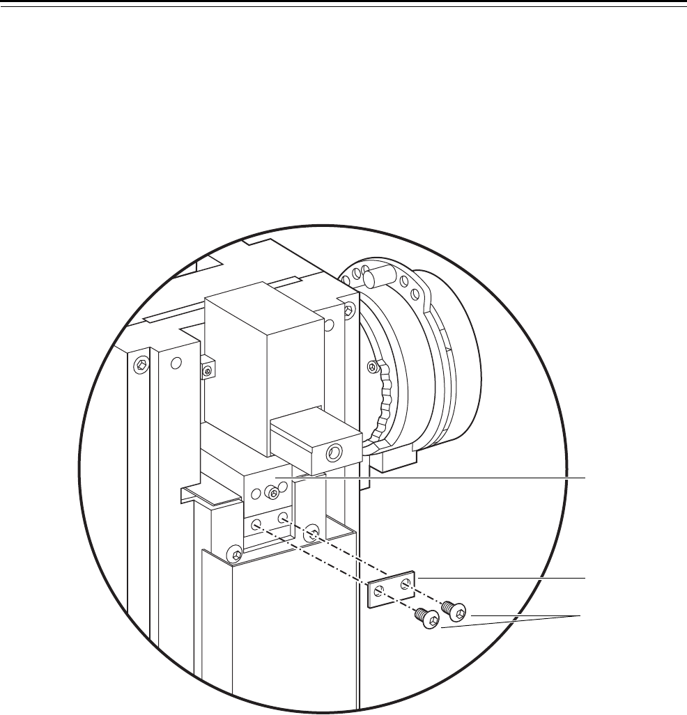
To remove the key carriage:
1. Using a 1/8″ Allen wrench, unscrew the two fastener screws at the
rear of the key carriage. Remove the rear stop plate from the back of
the key carriage, as shown in Figure 3.9.
2. From the front of the combinator, grip the key clamp knob and pull
the key carriage out of the combinator. See Figure 3.10.
Figure 3.9 Removing the key carriage
Rear view of combinator
Key carriage
Stop plate
Fastener
screws
Service and Maintenance
3–12 Key Combinator Service Manual
To reinstall the key carriage:
1. Wipe off any excess grease and oil from the key carriage. Wipe off
any chips that have built up inside the combinator or on the key
stop area.
2. Lightly lubricate both the right and left sides of the key carriage
(page 3–28).
Note: Use only a #10 non-detergent motor oil.
3. Carefully slide the key carriage into the slots on each side of the top
plate assembly. See Figure 3.10.
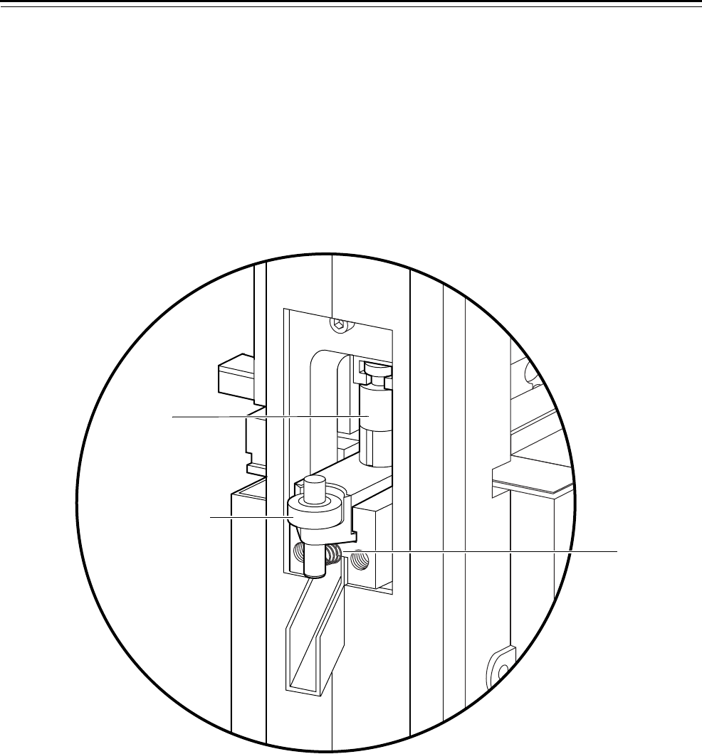
4. Locate the spring-loaded plungers along the side rail of the top plate.
See Figure 3.11.
5. From the rear of the combinator, press in each spring-loaded
plunger with a screwdriver so that the key carriage can slide past.
See Figure 3.11.
Caution
Be careful not to damage the spring-loaded plungers when pressing
against them with a screwdriver.
Figure 3.10 Reinstalling the key carriage
ALIBRATE
YSTEM A2
Key
carriage
Key stop area
Top plate
assembly
Key clamp
knob
Service and Maintenance
Key Combinator Service Manual 3–13
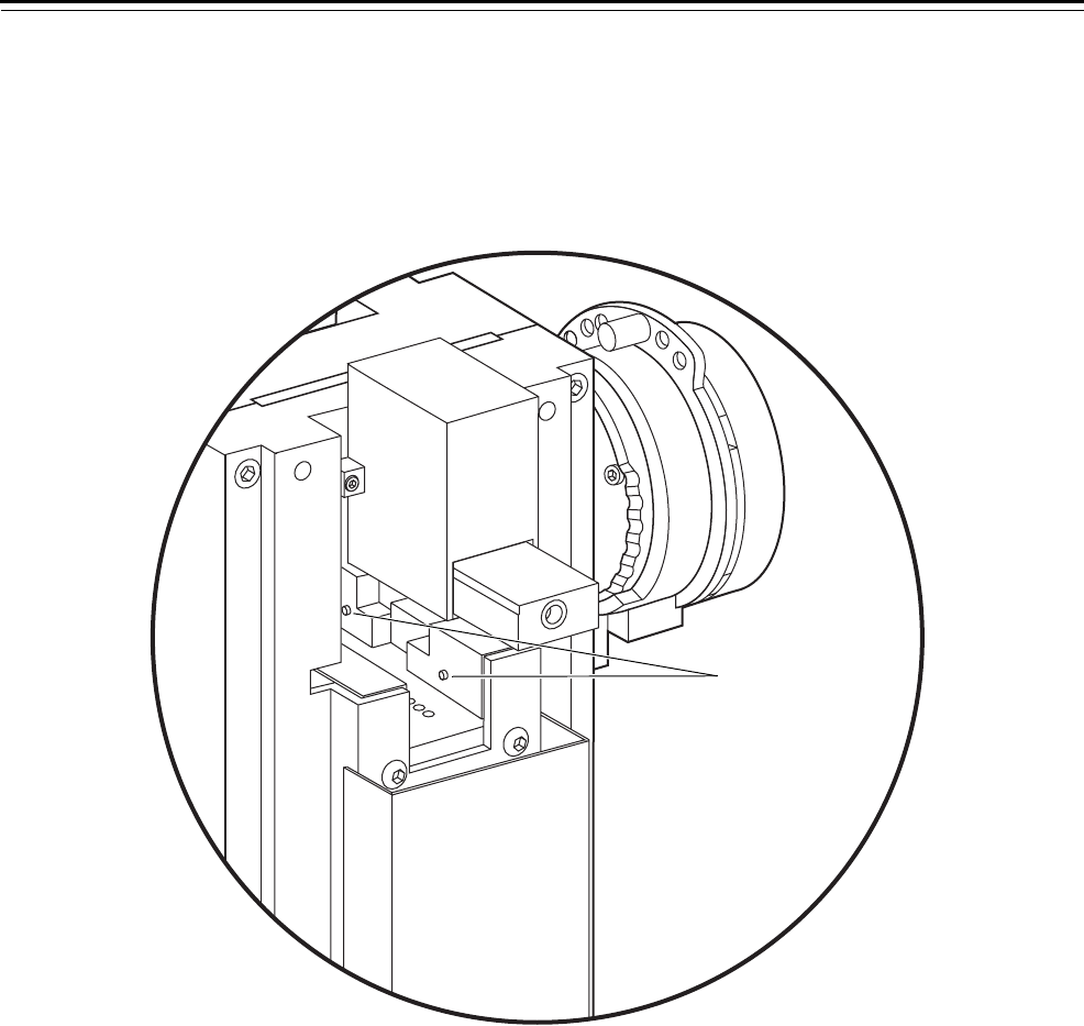
6. With the key carriage in place, install the rear stop plate with the
two fastener screws onto the back of the key carriage. Secure the
screws using a 1/8″ Allen wrench.
7. Calibrate a key to make sure the new key carriage is properly
installed (page 3–16).
Replacing the
operating lever
To remove the operating lever:
1. Make sure that the key carriage is pushed completely into the key
combinator housing.
2. Using a 5/32″ Allen wrench, remove the two front screws on the
operating lever frame. Save the screws.
3. Pull down the operating lever so that it rests against the rubber
bumper on its own. See Figure 3.12.
Figure 3.11 Depressing the key carriage plungers
Plungers
Rear view of combinator
Service and Maintenance
3–14 Key Combinator Service Manual
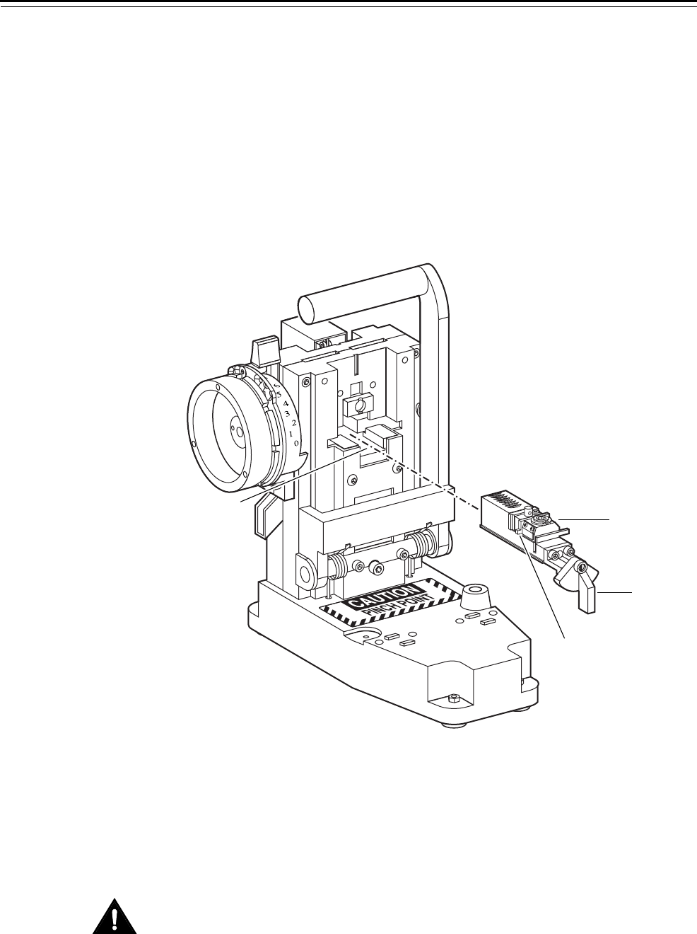
4. Pull the base of the operating lever assembly up and out of the key
combinator housing.
Caution
Keep your fingers away from the springs when removing this
assembly. The operating handle is spring-loaded, and springs will
disengage and could scratch your fingers.
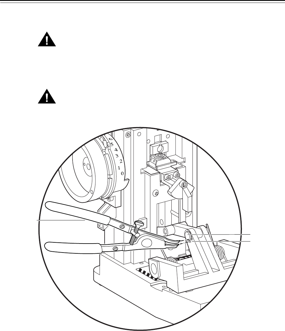
5. Using circlip pliers, insert the plier prongs into the holes of the
retainer ring that is wrapped around the lever pin. You can remove
the retainer ring on either side of the lever pin. See Figure 3.12.
Caution
Be careful not to distort the shape of the retainer ring when removing
it. Doing so can permanently damage the retainer ring, causing the
operating lever to malfunction.
6. Remove the retainer ring. Save the retainer ring.
7. Slide the lever pin out of the operating lever assembly. Save the
lever pin.
8. Remove the operating lever.
Figure 3.12 Removing the operating lever
ALIBRATE
YSTEM A2
Lever pin
Retainer ring
Circlip pliers
Front view of combinator
Service and Maintenance
Key Combinator Service Manual 3–15
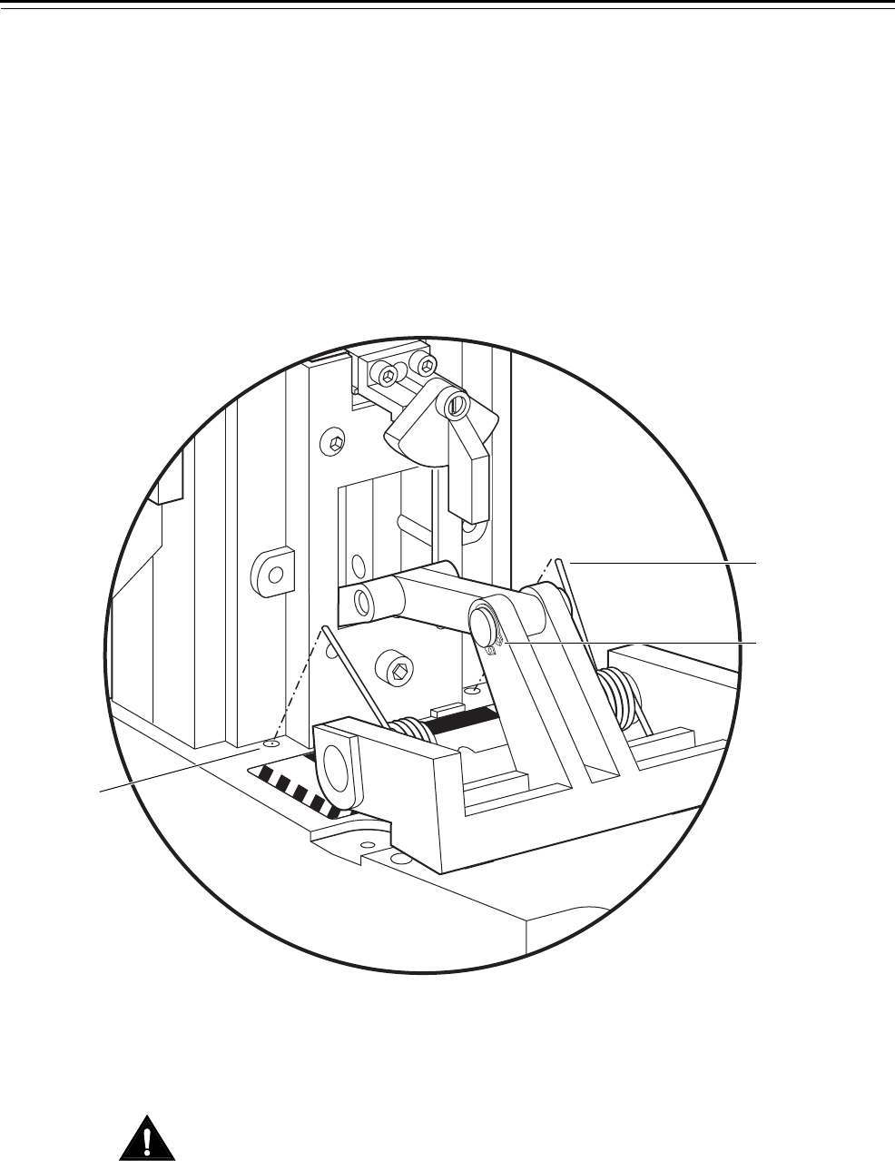
To reinstall the operating lever:
1. With the operating handle resting on the key combinator base, align
the holes in the operating lever with the holes on the lever branch
and slide the lever pin into position. The lever pin may be difficult
to insert in the holes. See Figure 3.12.
2. Using the circlip pliers, place the retainer ring around the lever pin
and secure the retainer ring in place. See Figure 3.12.
3. Adjust the springs so the ends fit into the spring holes on the base of
the combinator housing. See Figure 3.13. Place the other ends of the
springs into the spring slots on the operating lever frame.
4. With the springs in place, push the operating lever assembly back
into the key combinator housing so that the operating handle is
upright and resting against the combinator frame.
Caution
When pushing the assembly back into the combinator housing, keep
your fingers away from the springs so your fingers do not get
pinched.
5. Using a 5/32″ Allen wrench, install the two front screws and tighten
until the operating handle is properly aligned.
Figure 3.13 Reinstalling the operating lever
CAUTION
PINCH POINT
ALIBRATE
YSTEM A2
Spring slot
Spring
Retainer ring
Front view of combinator

Service and Maintenance
3–16 Key Combinator Service Manual
CALIBRATING THE KEY COMBINATOR
Occasionally you will need to calibrate your combinator’s cutting depth
to make sure that keys are being cut properly.
Cutting a
calibration key
To cut a calibration key:
1. Gripping the key clamp knob, pull the key carriage completely
forward.
2. Turn the key clamp knob counterclockwise to open the key clamp
spring (for left-handed combinators, turn the key clamp knob
clockwise). See Figure 3.2 (page 3–4).
3. With the curved edge of the key blank against the locating surface,
slide the key blank into the key opening. Make sure that the knife
edge of the key clamp spring fits into the groove of the key. See
Figure 3.3 (page 3–5).
4. Turn the key clamp knob clockwise, locking the key blank into the
key carriage (for left-handed combinators, turn the key clamp knob
counterclockwise).
The key clamp knob hangs loosely in the six o’clock position, as
shown in Figure 3.3 (page 3–5).
Service and Maintenance
Key Combinator Service Manual 3–17
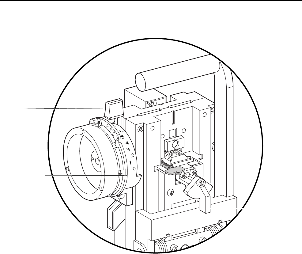
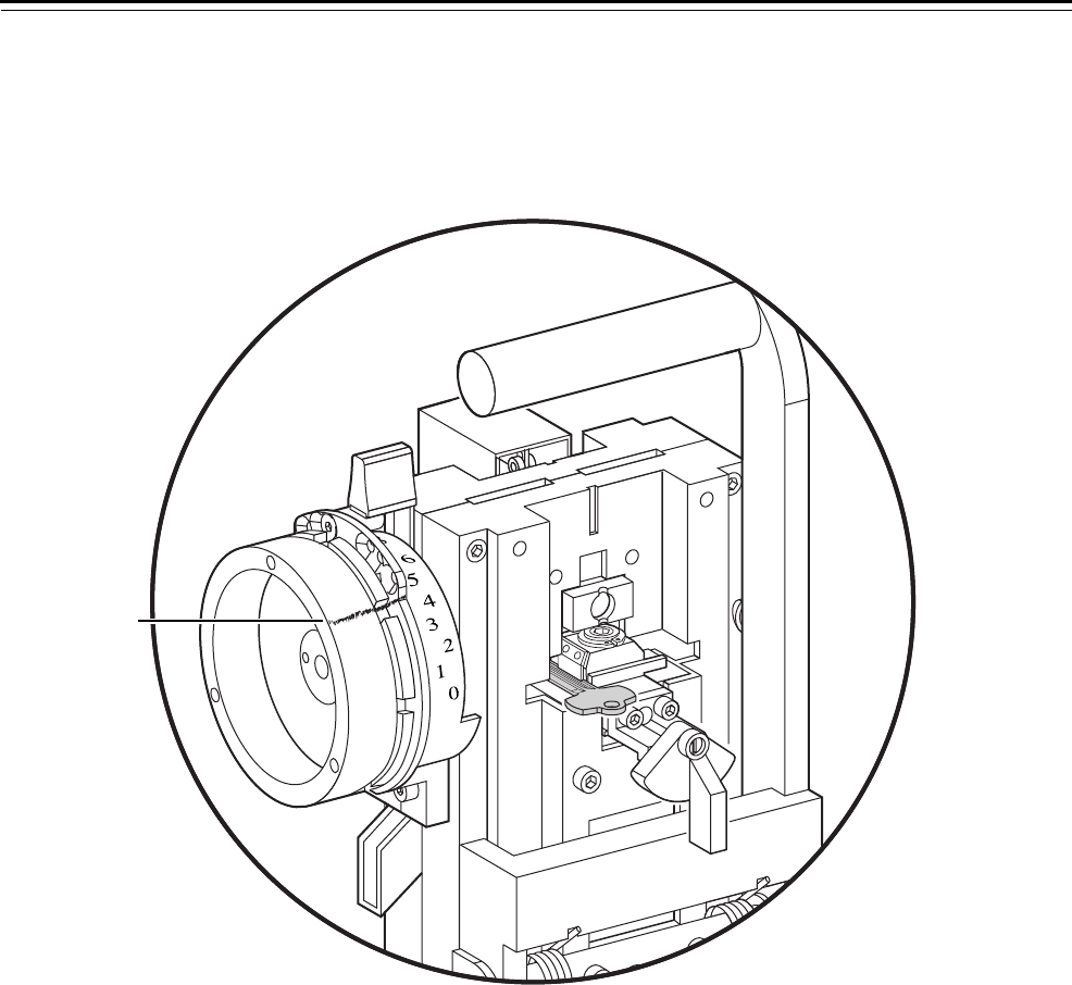
5. Move the dial on the depth selector assembly to the “CALIBRATE” line,
which is located below “0”, as shown in Figure 3.14.
6. Pull the operating lever down firmly until it strikes the rubber
bumper; then, let the operating lever move back to its original
position.
Note: The first stroke of the operating lever does not make a keycut;
it only moves the key into proper position for the first cut.
The key carriage and key blank are now in place for the first cut.
7. With the depth selector still set to “CALIBRATE,” pull the operating
lever down firmly until it strikes the rubber bumper; then, let the
operating lever move back to its original position.
The combinator makes the first cut and automatically moves the key
carriage and key blank into place for the next cut.
8. Repeat Step 7 until you have made all seven cuts on the key at
calibration depth.
9. Gripping the key clamp knob, pull the key carriage completely
forward.
Figure 3.14 Cutting a calibration key
ALIBRATE
YSTEM A2
Calibrate line
Dial
Key clamp knob
Front view of combinator
Service and Maintenance
3–18 Key Combinator Service Manual
10. Turn the key clamp knob counterclockwise (for left-handed
combinators, turn the key clamp knob clockwise).
11. Slide the key out.
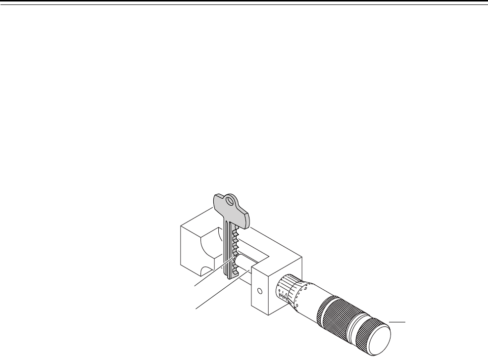
Placing the key
in the gauge
To place the key in the gauge:
1. Insert the blade of the key into the key gauge frame. Secure the key
so that the key blade is flat against the back of the frame, and the
bottom of the key is against the base of the frame.
2. Adjust the key so that the spindle is centered in between the third
and fourth keycut, as shown in Figure 3.15.
3. Grip the thimble and slowly turn it clockwise to move the spindle
towards the key. When the spindle is touching the key and will not
go any closer, the key gauge produces a “clicking” sound; you can
stop turning the thimble.
Reading the
gauge
If you have an AD502D digital key gauge, read the measurement
displayed on the screen and skip to the section “Checking the
measurement.” For a manual key gauge, refer to Figure 3.16 and
perform the steps below.
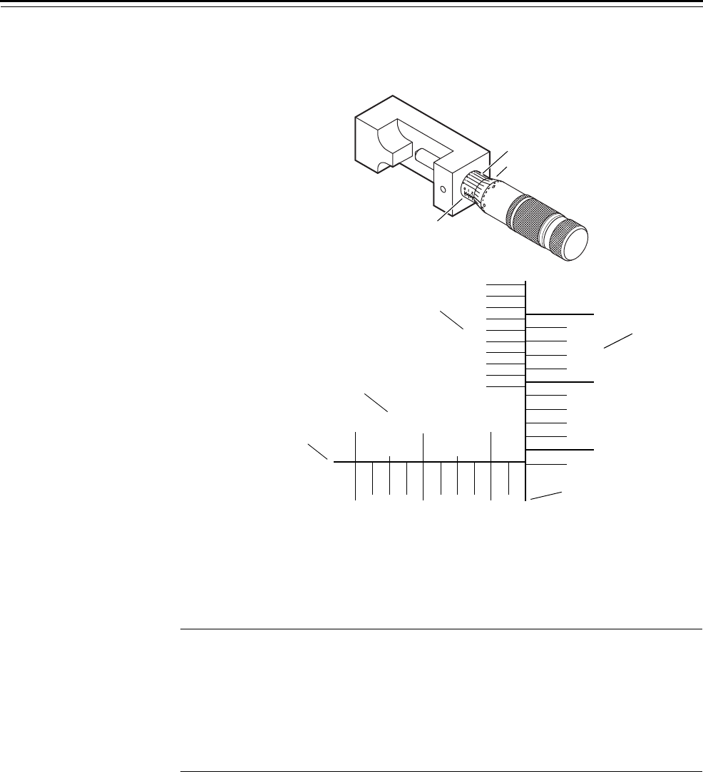
To read the key gauge:
1. On Scale 1, read the largest visible number. Each number on Scale 1
stands for 0.100″ (one hundred thousandths of an inch). Each line
on Scale 1 stands for 0.025″ (twenty-five thousandths of an inch).
2. On Scale 1, count the number of lines between the largest number
and the end of the thimble.
3. On Scale 2, read the largest number that is even with or just below
the centerline of Scale 1. Each line on Scale 2 stands for 0.001″ (one
thousandth of an inch).
Figure 3.15 Inserting a key into the key gauge
Keycut
Spindle
Thimble
Service and Maintenance
Key Combinator Service Manual 3–19
4. On Scale 3, read the line that best aligns with a line on Scale 2. Each
line on Scale 3 stands for 0.0001″ (one ten-thousandth of an inch).
Totaling the
measurement
To find the depth of the keycut, add the values from the three scales.
The table below shows an example.
Checking the
measurement
For each of the masterkey systems, the target calibration measurement
is 0.2500″. However, the key combinator is still considered to be within
the calibration range if your measurement is between 0.2490″ and
0.2510″.
If your keycut measurement falls within this range, the key combinator
does not need adjustment. If your measurement is outside this range,
you need to adjust the depth selector or contact your BEST
Representative.
Figure 3.16 Calibration measurement scale
012
0
5
10
1
24
2
3
4
6
7
8
9
1
2
3
4
5
6
7
8
9
10
Centerline of Scale 1
Scale 1
Scale 3
Scale 2
End of thimble
Scale 1
Scale 2
Scale 3
Step Scale Reading Number Value
1 1 Largest number visible 2 0.2000″
2 1 Number of visible lines between the largest
number and the thimble
1 0.0250″
3 1 and 2 Largest number on scale 2 that is even with or
below the centerline of scale 1
24 0.0240″
4 2 and 3 Line on scale 3 that best aligns with a line on
scale 2
5 0.0005″
Total: 0.2495″
Service and Maintenance
3–20 Key Combinator Service Manual
Adjusting the
depth selector
To adjust the depth selector for a micrometer reading measuring less
than 0.2490″:
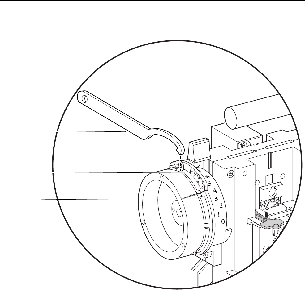
1. With a lead or grease pencil, mark a straight line across the depth
selector assembly. See Figure 3.17.
Figure 3.17 Marking the depth selector assembly
ALIBRATE
YSTEM A2
Mark across
depth selector
assembly
Front view of combinator
Service and Maintenance
Key Combinator Service Manual 3–21
2. While holding the depth adjuster in place, use a spanner wrench to
loosen the spanner nut. See Figure 3.18.
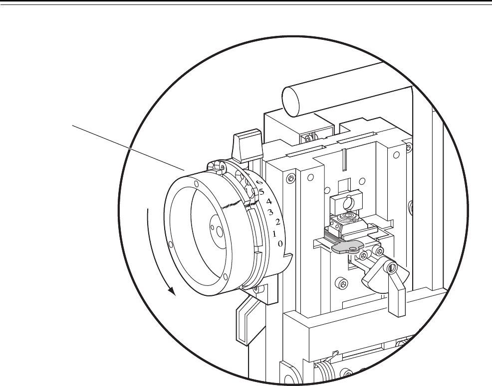
3. Turn the depth adjuster counterclockwise (turning the depth
adjuster 1/4″ changes the cut depth by 0.001″—one thousandth of
an inch). Use the lead or grease mark as your reference. See
Figure 3.19.
Figure 3.18 Loosening the spanner nut
ALIBRATE
YSTEM A2
Spanner wrench
Spanner nut
Depth adjuster
Front view of combinator
Service and Maintenance
3–22 Key Combinator Service Manual
.
4. While holding the depth adjuster in place, tighten the spanner nut.
If the depth adjuster moves while you are tightening the spanner
nut, go to Step 5. Otherwise, go to Step 6.
5. If the depth adjuster moves while you are tightening the spanner
nut:
■Loosen the spanner nut again.
■Return the depth adjuster to its original position, using the lead or
grease mark as your reference.
■Repeat Step 2 through Step 4.
6. Perform the following steps:
■Cut the calibration key (page 3–16).
■Place the key in the gauge (page 3–18).
■Read the gauge (page 3–18).
■Total and check the measurement (page 3–19).
Note: The new keycut depth should be within calibration range. If
not, send the key combinator to the BEST factory for repair.
Figure 3.19 Turning the depth adjuster counterclockwise
ALIBRATE
YSTEM A2
Rotate the depth adjuster
counterclockwise.
Front view of combinator
Depth adjuster
Service and Maintenance
Key Combinator Service Manual 3–23
To adjust the depth selector for a micrometer reading measuring more
than 0.2510″:
1. With a lead or grease pencil, make a mark across the depth selector
assembly. See Figure 3.17.
2. While holding the depth adjuster in place, use the spanner wrench
to loosen the spanner nut. See Figure 3.18.
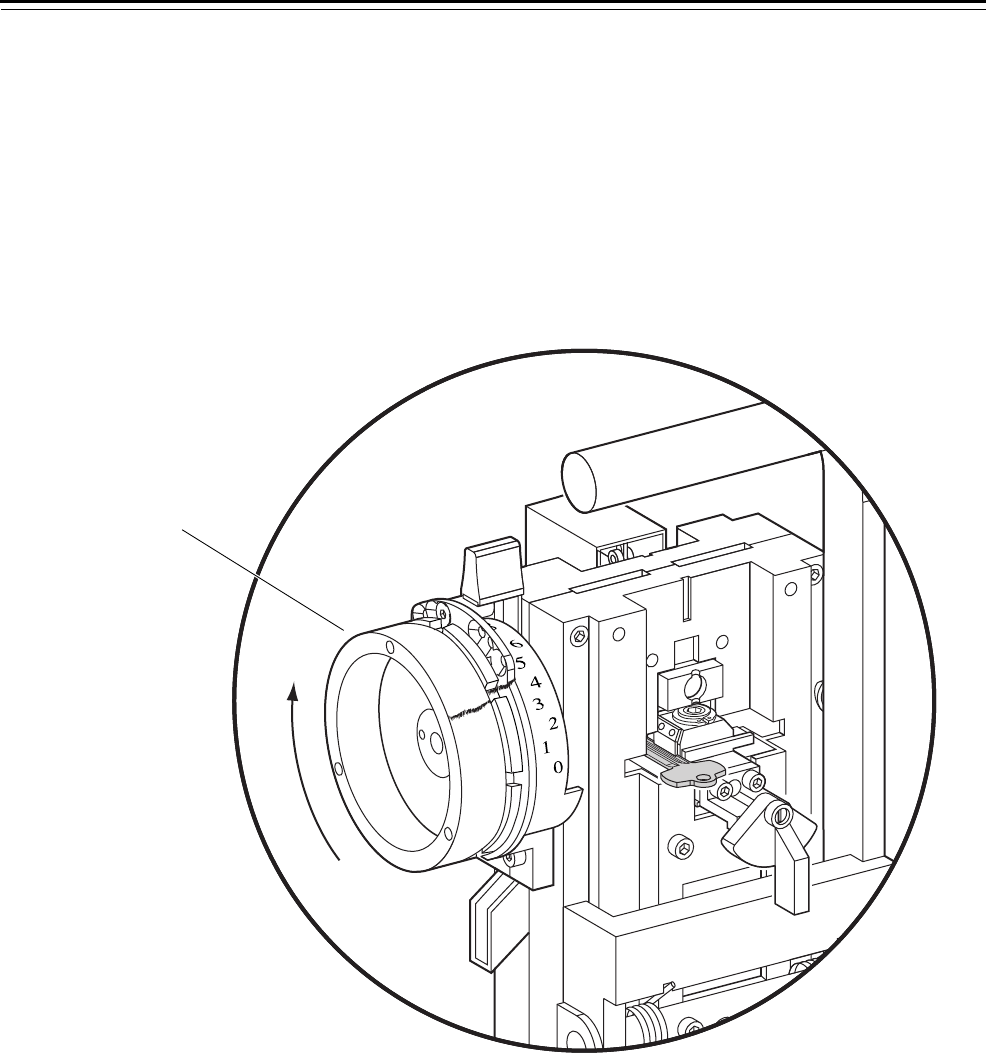
3. Rotate the depth adjuster clockwise (turning the depth adjuster 1/4″
changes the cut depth by 0.0010″—one thousandth of an inch). Use
the lead or grease mark as a reference. See Figure 3.20.
4. While holding the depth adjuster in place, tighten the spanner nut.
If the depth adjuster moves while you are tightening the spanner
nut, go to Step 5. Otherwise, go to Step 6.
Figure 3.20 Turning the depth adjuster clockwise
ALIBRATE
YSTEM A2
Rotate the depth
adjuster clockwise.
Front view of combinator
Depth adjuster

Service and Maintenance
3–24 Key Combinator Service Manual
5. If the depth adjuster moves while you are tightening the spanner
nut:
■Loosen the spanner nut again.
■Return the depth adjuster to its original position, using the lead or
grease mark as your reference.
■Repeat Step 2 through Step 4.
6. Perform the following steps:
■Cut the calibration key (page 3–16).
■Place the key in the gauge (page 3–18).
■Read the gauge (page 3–18).
■Total and check the measurement (page 3–19).
Service and Maintenance
Key Combinator Service Manual 3–25
ADJUSTING THE KEY CLAMP SPRING
Because keys may vary slightly in thickness, you may need to
occasionally adjust the key clamp spring to make sure that keys are
properly clamped in the key carriage.
If your key is either difficult to insert or too loose to clamp into place,
perform the following steps.
To adjust the key clamp spring:
1. Gripping the key clamp knob, pull the key carriage completely
forward.
2. Raise the key clamp spring by turning the key clamp knob
counterclockwise, as shown in Figure 3.21 (for left-handed
combinators, turn the key clamp knob clockwise).
3. Slide a key blank into the key carriage.
If the key is difficult to insert, go to Step 4a.
If the key is too loose to clamp in place, go to Step 4b.
Figure 3.21 Loading a key
ALIBRATE
YSTEM A2
Key carriage
Key clamp knob
Key blank
Front view of combinator
Service and Maintenance
3–26 Key Combinator Service Manual
4a. If the key is difficult to insert, use a 5/32″ Allen wrench to turn the
adjustment screw clockwise, in 30° increments, until you achieve
the appropriate insertion force. You may need to pull the operating
lever down slightly to properly position your Allen wrench. See
Figure 3.22. A small amount of drag on the key is needed.
Go to Step 5.
4b. If the key is too loose to clamp in place, use a 5/32″ Allen wrench to
turn the adjustment screw counterclockwise, in 30° increments,
until you achieve the appropriate insertion force. You may need to
pull the operating lever down slightly to properly position your
Allen wrench. See Figure 3.22. A small amount of drag on the key is
needed.
Go to Step 5.
5. Turn the key clamp knob completely clockwise to clamp the key
blank into the key carriage (for left-handed combinators, turn the
clamp knob counterclockwise).
6. Calibrate a key to make sure the key clamp spring is properly
adjusted (page 3–16).
Figure 3.22 Adjusting the key clamp spring
ALIBRATE
YSTEM A2
Operating lever
Allen wrench
Adjustment
screw
Key clamp knob

Service and Maintenance
Key Combinator Service Manual 3–27
PREVENTATIVE MAINTENANCE
Preventative maintenance is vital for keeping your key combinator
functioning properly. To ensure accurate keycuts and avoid possible
malfunctions, periodically perform the tasks below. It is also a good
idea to keep your key combinator covered whenever it is not in use.
Doing so will help keep dust and other foreign particles out of the
crevices of the combinator.
To help maintain your key combinator, perform the following tasks:
■Clean (wipe down) the following items:
▲chip chute to remove metal chips
▲outside of key combinator to remove dust and other particles
▲key carriage compartment to remove dust and
metal chips (page 3–27)
▲punch and die compartment to remove dust and
metal chips (page 3–27).
■Check for and tighten any loose screws.
■Adjust the key clamp spring as needed (page 3–25).
■Calibrate for consistency (page 3–16).
■Lubricate necessary parts (page 3–28).
See the BEST Key Combinator Preventative Maintenance Record
Sheet in Appendix B of this manual to help you keep records of your
maintenance tasks.
CLEANING PARTS
Cleaning the
punch and die
To clean the punch and die:
1. Remove the depth selector (page 3–7).
2. Remove the punch and die assembly (page 3–9).
3. Wipe out any key chips and dust from the compartment. Do not
lubricate this area.
4. Lubricate both sides of the die (page 3–28).
5. Reinstall the punch and die assembly (page 3–10).
6. Reinstall the depth selector (page 3–8).
Cleaning the
key carriage
To clean the key carriage:
1. Remove the key carriage (page 3–11).
2. Wipe out any chips and dust from the compartment.
3. Lubricate both sides of the carriage (page 3–28).
4. Reinstall the key carriage (page 3–11).

Service and Maintenance
3–28 Key Combinator Service Manual
LUBRICATING PARTS
It is important to lubricate your key combinator regularly with a quality
#10 non-detergent motor oil. Signs that your combinator is overdue for
lubrication include:
■squeaking sounds
■corrosion
■difficulty making keycuts
■tightness in moving the operating lever.
Guidelines for
lubrication
To avoid damaging your combinator and causing inaccurate keycuts,
please adhere to the following:
■Apply only enough oil to barely wet the appropriate points to avoid
overlubricating your combinator.
■Do not lubricate the chip chute, the depth selector, or the roller on
the punch and die. Chips could stick to these parts, causing
malfunctions.
■Do not apply any type of silicone-based lubricant to your
combinator. Doing so may void your warranty or service agreement.
■Do not use an air hose to remove chips or dust from the key
combinator. Doing so may void your warranty or service agreement.
Lubricating the
key combinator
housing
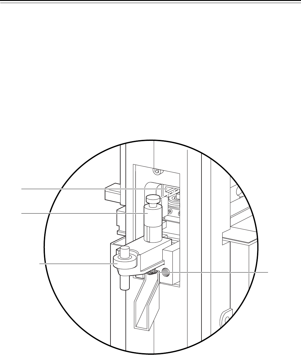
To lubricate the outer frame/housing of the key combinator:
1. Apply one drop of oil into each of the upper front holes and rear
holes. See Figure 3.23.
2. Apply one drop of oil into the 3/8″ diameter pin located above the
adjustment screw.
To lubricate the key carriage:
1. Apply one drop of oil into the 1/4″ diameter pin located on top of
the key carriage.
2. Apply one drop of oil on both sides of the key carriage’s sliding
surfaces. See Figure 3.23.
Slide the key carriage in and out as you lubricate.
Service and Maintenance
Key Combinator Service Manual 3–29
To lubricate the operating lever:
1. Apply one drop of oil onto each side of the operating lever frame.
See Figure 3.23.
2. Apply one drop of oil onto the springs connected to the operating
lever.
3. Apply one drop of oil to each of the other linkages that you can
conveniently reach.
You need to pull down and hold the operating lever to reach some
of these areas.
Figure 3.23 Lubricating parts
ALIBRATE
YSTEM A2
Upper front holes
Springs
3/8” diameter pin
Key carriage assembly
Operating lever frame
Service and Maintenance
3–30 Key Combinator Service Manual
To lubricate the punch and die:
1. Remove the following items:
■depth selector assembly (page 3–7)
■punch and die assembly (page 3–9).
2. Apply one drop of oil each of the sides of the die block. See
Figure 3.24. Do not lubricate the roller or the punch and die
compartment.
3. Reinstall the following items:
■punch and die assembly (page 3–10)
■depth selector assembly (page 3–8).
Figure 3.24 Lubricating the punch and die
Side view of combinator
Die block
Roller
Punch

Service and Maintenance
Key Combinator Service Manual 3–31
TROUBLESHOOTING
This table summarizes the possible causes for the most common key
combinator problems. The causes are listed in the order of likelihood.
(The most likely cause is first, and so forth.)
You notice… Possible causes include… You should…
Key is difficult to insert in the key
combinator.
a. Key clamp spring is closed. a. Turn the key clamp knob to open
the key clamp spring.
b. Key clamp spring needs to be
adjusted.
b. Adjust the key clamp spring until
the key feels tightly secured in the
key carriage (page 3–25).
Key is loose in the key carriage. a. Key clamp spring is open. a. Turn the key clamp knob to close
the key clamp spring.
b. Key clamp spring needs to be
adjusted.
b. Adjust the key clamp spring until
the key feels tightly secured in the
key carriage (page 3–25).
Depth selector is jammed or will
not allow selection of deeper cuts.
Chips are lodged in the guide rails. Remove the punch and die and clear
away the chips from the guide rails
(page 3–27).
There is a burr in the keycut. a. Handle was not depressed
completely.
a. Recut the key (page 3–4).
b. Punch and die are worn. b. Replace the punch and die
(page 3–9).
Keycut depth is incorrect. a. Depth selector was not released
when the cut was made.
a. Follow the steps for cutting keys
(page 3–4).
b. Cutting depth needs to be
calibrated.
b. Calibrate the depth of the cut
(page 3–16).
c. There are chips on the depth
selector.
c. Remove the depth selector
(page 3–7) and clear away the
chips.
d. There are chips on the die
assembly roller.
d. Remove the depth selector
(page 3–7) as well as the punch
and die (page 3–9). Clear away the
chips.
Operating handle is difficult to pull
down.
a. Retainer ring is hyper extended. a. Replace the retainer ring.
b. Operating lever needs to be
lubricated.
b. Lubricate the lever handle
(page 3–29).
Keycut spacing is incorrect. Key carriage does not move or
moves inconsistently.
Remove the key carriage and clear
away any chips. If the problem persists,
return the combinator to BEST for
repair.

Service and Maintenance
3–32 Key Combinator Service Manual

Key Combinator Service Manual A–1
AGLOSSARY
Calibrate To check against a known standard and adjust to that
standard.
Calibration depth Standard keycut measurement (.2500″) that the key
combinator should cut when the calibration position
is selected.
Calibration
position
Position on the depth selector that, when selected,
sets up the key combinator to cut the calibration
depth keycut.
Core See interchangeable core.
Depth selector Dial on the key combinator, marked with numbers,
that is used for selecting keycut depths.
Figure-8 Shape of the interchangeable core and its housing
(housings include door knob, cylinder, padlock, and
so forth).
Interchangeable
core
Figure-8 shaped device that contains all the
mechanical parts for a masterkey system. The
interchangeable core can be removed with a special
control key and recombinated without disassembling
the lock.
Key blank Key with a keyway shape, but without keycuts.
Key carriage Housing that moves the key to each keycut position.
Key clamp knob Knob that operates the key clamp spring and that is
used to pull out or push in the key carriage.
Key clamp spring Part of the key combinator that holds the key in
place.

Glossary
A–2 Key Combinator Service Manual
Key combinator Machine that notches cuts into BEST key blanks for BEST masterkey
systems.
Keycut Notch in a key that fits a corresponding pin segment of a core.
Keycut depth Distance from the bottom of the keycut to the underside of the key
blade.
Key gauge AD502 gauge that measures keycut depths. This gauge is used to
calibrate the key combinator.
Keying system Method of keying locks.
Keyway Cross-section shape milled into the key blank and broached into core
plugs.
Left-handed key
combinator
Key combinator that cuts only patented or left-handed premium keys.
Masterkeying Process of combinating locks to allow a single key to operate many
locks and to allow each lock to be operated by a unique key at the same
time.
Punch and die Part of the key combinator that notches keys to a precise shape.
Right-handed key
combinator
Key combinator that cuts only standard or right-handed premium keys.
Setup stroke First stroke of the operating lever that positions the key for cutting.

Key Combinator Service Manual B–1
BPREVENTATIVE MAINTENANCE
Use the following page to record periodic cleaning
and maintenance tasks that are performed on your
key combinator. The frequency with which you
perform these tasks may vary based on your specific
needs.

Preven
t
a
t
ive Main
t
enance
B–2 Key Combinator Service Manual
BEST Key Combinator Preventative Maintenance Record Sheet
Task Record date and initial when task is completed
Clean and dust
the outside of
the combinator
Date:
By:
Date:
By:
Date:
By:
Date:
By:
Date:
By:
Date:
By:
Date:
By:
Date:
By:
Date:
By:
Date:
By:
Date:
By:
Date:
By:
Date:
By:
Date:
By:
Date:
By:
Date:
By:
Date:
By:
Date:
By:
Date:
By:
Date:
By:
Date:
By:
Date:
By:
Date:
By:
Date:
By:
Date:
By:
Date:
By:
Date:
By:
Date:
By:
Date:
By:
Date:
By:
Date:
By:
Date:
By:
Date:
By:
Date:
By:
Date:
By:
Date:
By:
Clean the key
carriage
Date:
By:
Date:
By:
Date:
By:
Date:
By:
Date:
By:
Date:
By:
Date:
By:
Date:
By:
Date:
By:
Date:
By:
Date:
By:
Date:
By:
Date:
By:
Date:
By:
Date:
By:
Date:
By:
Date:
By:
Date:
By:
Date:
By:
Date:
By:
Date:
By:
Date:
By:
Date:
By:
Date:
By:
Date:
By:
Date:
By:
Date:
By:
Date:
By:
Date:
By:
Date:
By:
Date:
By:
Date:
By:
Date:
By:
Date:
By:
Date:
By:
Date:
By:
Clean the
punch and die
Date:
By:
Date:
By:
Date:
By:
Date:
By:
Date:
By:
Date:
By:
Date:
By:
Date:
By:
Date:
By:
Date:
By:
Date:
By:
Date:
By:
Date:
By:
Date:
By:
Date:
By:
Date:
By:
Date:
By:
Date:
By:
Date:
By:
Date:
By:
Date:
By:
Date:
By:
Date:
By:
Date:
By:
Date:
By:
Date:
By:
Date:
By:
Date:
By:
Date:
By:
Date:
By:
Date:
By:
Date:
By:
Date:
By:
Date:
By:
Date:
By:
Date:
By:
Lubricate the
necessary parts
Date:
By:
Date:
By:
Date:
By:
Date:
By:
Date:
By:
Date:
By:
Date:
By:
Date:
By:
Date:
By:
Date:
By:
Date:
By:
Date:
By:
Date:
By:
Date:
By:
Date:
By:
Date:
By:
Date:
By:
Date:
By:
Date:
By:
Date:
By:
Date:
By:
Date:
By:
Date:
By:
Date:
By:
Date:
By:
Date:
By:
Date:
By:
Date:
By:
Date:
By:
Date:
By:
Date:
By:
Date:
By:
Date:
By:
Date:
By:
Date:
By:
Date:
By:
Calibrate for
consistency†
Date:
By:
Date:
By:
Date:
By:
Date:
By:
Date:
By:
Date:
By:
Date:
By:
Date:
By:
Date:
By:
Date:
By:
Date:
By:
Date:
By:
Date:
By:
Date:
By:
Date:
By:
Date:
By:
Date:
By:
Date:
By:
Date:
By:
Date:
By:
Date:
By:
Date:
By:
Date:
By:
Date:
By:
Date:
By:
Date:
By:
Date:
By:
Date:
By:
Date:
By:
Date:
By:
Date:
By:
Date:
By:
Date:
By:
Date:
By:
Date:
By:
Date:
By:
† Calibrate whenever you service your key combinator as well.

Key Combinator Service Manual C-1
CINDEX
A
adjusting the depth selector
for key cut measuring less than 0.2490"
3–20
for key cut measuring more than 0.2510"
3–23
adjusting the key clamp spring 3–25
C
calibrating
checking the measurement 3–19
cutting the key 3–16
placing the key in the gauge 3–18
reading the gauge 3–18
totaling the measurement 3–19
circlip pliers 3–2
cleaning
general tips 3–27
key carriage 3–27
punch and die 3–27
D
depth selector
A2 assembly 2–2 to 2–3
A3 assembly 2–2 to 2–3
A4 assembly 2–2 to 2–3
adjusting 3–20
reinstalling 3–8
removing 3–7
documentation package
see technical documentation package
drawings, of parts
see part numbers and drawings
E
exploded diagrams
see part numbers and drawings
K
key calibration gauge 3–2
key carriage
6-pin Peaks assembly 2–2
7-pin Peaks assembly 2–2
cleaning 3–27
lubricating 3–28
premium assembly 2–2 to 2–3
reinstalling 3–12
removing 3–11
standard assembly 2–3
key clamp spring, adjusting 3–25
keys
cutting 3–5
loading 3–4
patented key 2–4
premium key 2–4
standard key 2–4
unloading 3–6
keyways 2–5
L
lubricating
combinator housing 3–28
guidelines to follow 3–28
key carriage 3–28
operating lever 3–29
punch and die 3–30

Index
C-2 Key Combinator Service Manual
M
machine handing 3–2
maintenance, preventative
general tasks 3–27
record sheet B–2
N
numbers, for parts
see part numbers and drawings
O
operating lever
lubricating 3–29
reinstalling 3–15
removing 3–13
standard assembly 2–2 to 2–3
P
part numbers and drawings
for circlip pliers 3–2
for key calibration guage 3–2
for left-handed key combinator
2–2
for patented key 2–4
for premium key 2–4
for right-handed key
combinator 2–3
for spanner wrench 3–2
for standard key 2–4
product family diagram 1–2
punch and die
cleaning 3–27
lubricating 3–30
Peaks assembly 2–2
reinstalling 3–10
removing 3–9
standard assembly 2–2 to 2–3
R
reinstalling
depth selector 3–8
key carriage 3–12
operating lever 3–15
punch and die 3–10
removing
depth selector 3–7
key carriage 3–11
operating lever 3–13
punch and die 3–9
S
spanner wrench 3–2
support, technical
see technical support
T
technical documentation package
1–3
technical support 1–3
troubleshooting 3–25
