BEST T81611b Installation Specifications For 45HW & 47HW Electrified Mortise Locks
User Manual: BEST Installation Specifications for 45HW & 47HW Electrified Mortise Locks Installation
Open the PDF directly: View PDF ![]() .
.
Page Count: 1
Rev dateTemplate
number
Rev
Title
T81611/Rev B ER-7991-1 Jan 2015
Backset ssenkciht rooDelyts mirTseireS
BEST A C CESS S Y STEMS
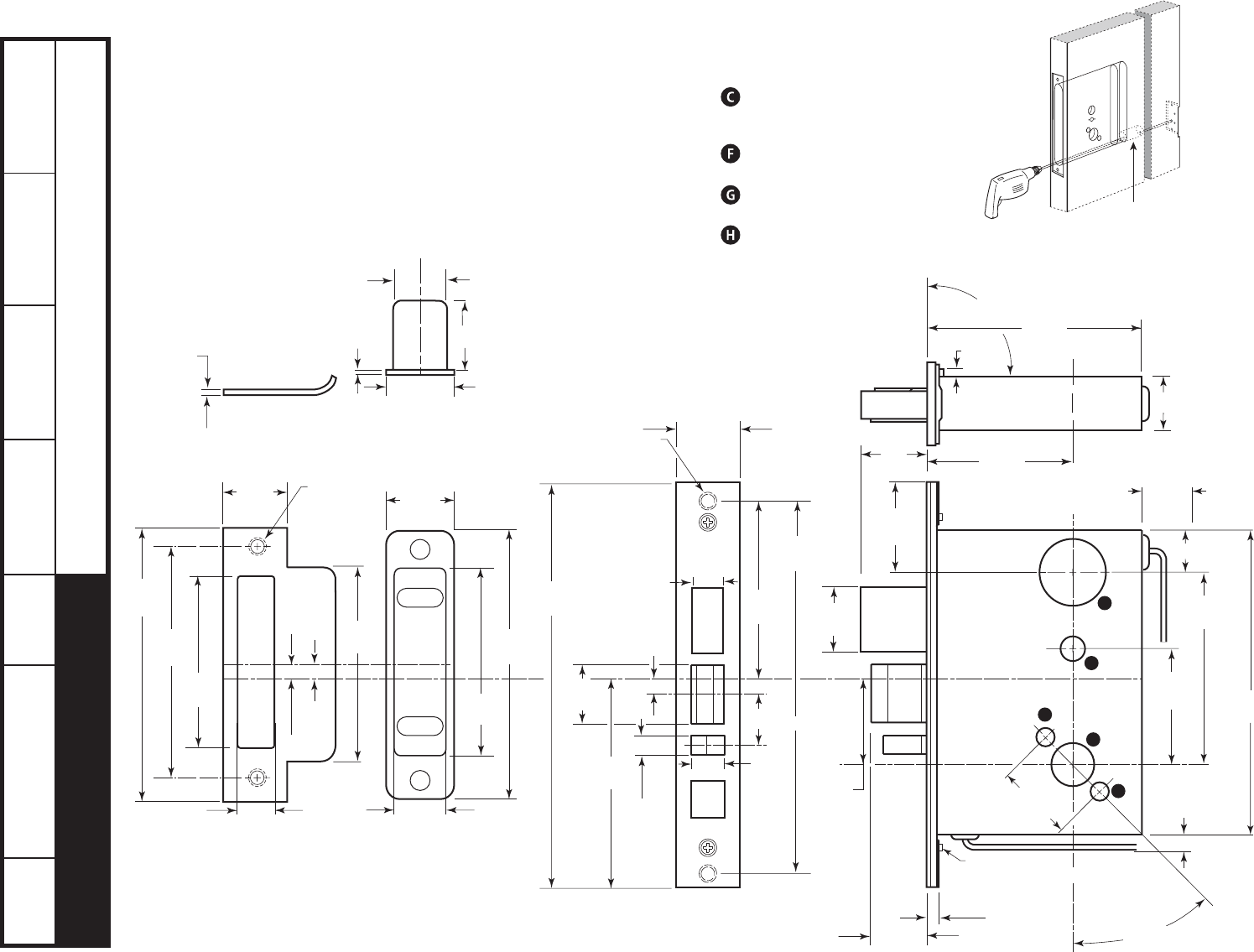
Installation Specications for 45HW & 47HW Electried Mortise Locks
H, J, M,
N, R, S 1/2007H19 B
2 3/4”45HW & 47HW1 3/4” to 5”
Mortise case — overhead view
3
/
32
in
(2.4 mm)
Strike plate —
overhead view
1
7
/
32
in
(31.0 mm)
31
/
32
in
(24.6 mm)
3
/
64
in
(1.2 mm)
1
1
/
32
in
(26.2 mm)
Strike box —
overhead view
3
3
/
64
in
(77.4 mm)
3
3
/
8
in
(85.7 mm)
1
1
/
4
in
(31.8 mm)
3
21
/
64
in
(84.5 mm)
4
7
/
8
in
(123.8 mm)
4
1
/
8
in
(104.8 mm)
11
/
16
in
(17.5 mm)
Centerline
of lock
Centerline
of strike
40HS1
Strike plate
2 x #12–24 screw
Note 5
3
/
8
in
(9.5 mm)
Strike box
15
/
16
in
(23.8 mm)
1
7
/
32
in
(31.0 mm)
Note 6
1
1
/
8
in
(28.6 mm)
1 in
(25.4 mm)
4 in
(101.6 mm)
9
/
16
in
(14.3 mm)
11
/
32
in
(8.7 mm)
5
/
8
in
(15.9 mm)
8 in
(203.2 mm)
7
1
/
4
in
(184.2 mm)
1
1
/
4
in
(31.8 mm)
Faceplate
2 x #12-24 screw
Note 5
7
/
32
in
(5.6 mm)
3
5
/
8
in
(92.1 mm)
1 in
(25.4 mm)
min. clearance
for wires
1
3
/
16
in
(30.2 mm)
1
7
/
8
in
(47.6 mm)
3
/
4
in
(19.1 mm)
1
1
/
2
in
(38.1 mm)
Centerline
of lever to
centerline
of lock
1
11
/
16
in
(42.9 mm)
7
/
32
in
(5.6 mm)
13
/
16
in
(20.6 mm)
2
27
/
64
in
(61.5 mm)
3
5
/
8
in
(92.1 mm)
5
7
/
8
in
(149.2 mm)
45 degrees
Clear for screws
1/16
in
(1.6 mm)
deep
3
/
8
in
(9.5 mm)
clearance for wires
4
25
/
32
in
(121.4 mm)
2
3
/
4
in
(69.9 mm)
backset
1 in
(25.4 mm)
1
/
8
in
(3.2 mm)
4
1
/
4
in
(108.0 mm)
Adjusts 90 degrees ± 3 ½ degrees
7
/
8
in
(22.2 mm)
C
F
G
H
G
Mortise case — side view
Notes
1. Before drilling, check the H15 Template:
Installation Template for 45H & 47H
Mortise Locks and 45HW & 47HW
Electried Mortise Locks (T81163).
2. The maximum door-to-frame gap is
3/16” (4.8mm).
3. Allow 3/64” (1.2mm) clearance for the
strike box thickness.
4. For metal doors, lock case support is
required from the door manufacturer.
5. Tap for a #12-24 machine screw or
drill for a #12 wood screw (a
combination screw is supplied)
6. If using an optional magnetic strike
box, position the magnet at the top.
Cylinder hole -
For 45HW Locks, 1¼” (32mm) dia.
For 47HW Locks, 1¾” (45mm) dia.
Emergency key / thumb turn access
hole -
½” (13mm) dia.
Trim mounting hole -
3
/8
”
(10mm) dia. (two required)
Lever hole - 7
/8
” (23mm) dia.
7. Lock case holes:
Prep TCM hole
1” dia x 3” deep hole
