BEXT 072503FMW300 XT 300 Frequency agile FM Transmitter User Manual xt300
BEXT Inc XT 300 Frequency agile FM Transmitter xt300
BEXT >
Contents
- 1. XT 300 User Manual Part1
- 2. XT 300 User Manual Part2
XT 300 User Manual Part1
Technical Manual
XT300
BEXT, Inc.
1045 Tenth Avenue
San Diego, Ca 92101 U.S.A.
Tel: 619-239-8462
Fax: 619-239-8474
E-mail: support @bext.com
Web Site: http://www.bext.com

XT300 and XT300/S
300W Mono and Stereo Synthesized Exciter 87.5-108 MHz
Technical and Maintenance Manual
Pag. 2

Pag. 4

WARNING: This is “class A” equipment. In a residential place this can cause R.F. Burns. In this
situation the user is recommended to take appropriate action.
Please observe safety precautions when handling this unit. This equipment contains dangerous
voltages and currents.
This manual is written as a general guide for those having previous knowledge and experience with
this kind of equipment. It is not intended to contain a complete statement of all safety precautions
which should be observe by people working on this or other electronic equipment.
Bext, Inc. doesn’t assume responsibility for injury or damage resulting from improper procedures or
practices by untrained/unqualified personnel in the handling of this unit.
Please observe all local codes and fire protection standards in the operation of this unit.
CAUTION: Always disconnect power before opening covers or removing any part of this unit. Use
appropriate grounding procedures to short out capacitors and high voltage points before servicing.
Any damage to the goods must be reported to the carrier in writing on the shipment receipt. Any
discrepancy or damage discovered subsequent to delivery, must be reported to Bext, Inc. within five
(5) days of receipt.
Bext, Inc. extends to the original end-user purchaser all original manufacturers’ warranties which are
transferable and all claims are to be made directly to Bext, Inc. per indicated procedures.
All manufacturers’ warranties will be supported by Bext, Inc. to ensure precise and speedy service
where possible.
Bext, Inc. shall not be liable for any damage of whatsoever nature, arising out of or in connection
with the product or its use.
Bext, Inc. warranty shall not include:
1) Reshipments of unit to Bext, Inc. for repair purposes
2) Any unauthorized repair/modification
3) Incidental/consequential damages as a result of any defect
4) Nominal non-incidental defects
5) Reshipment costs or insurance of the unit or replacement unit/parts
Warranty shall come into force from invoice date and for the period of manufactures’ warranty.
Pag. 5
PRELIMINARY INSTRUCTIONS AND WARRANTY INFORMATION
The warranty is good for a period of 24 months on any Bext, Inc. product, while for products such as
transistors, Mos-FET and tubes of the final stages, the warranty is based on the product’s
manufaturer’s warranty.
To claim your rights under this warranty:
a. Contact the dealer or distributor where you purchased the unit. Describe the problem and
ask if he has an easy solution. Dealer and distributors are supplied with all the information
about problems that may occur and usually they can repair the unit quicker than what the
manufacturer could do. Very often installation errors are discovered by dealers.
b. If your dealer cannot help you, contact Bext, Inc. and explain the problem. If it is decided to
the return the unit to the factory, Bext, Inc. will give you a return authorization and all the
necessary instructions to send back the goods.
c. When you receive the authorization, you can return the unit. Pack it carefully for shipment,
preferably using the original packing, and seal the package perfectly. The customer always
assumes the risks of loss (i.e., Bext, Inc. is never responsible for damage or loss), until the
package reaches Bext, Inc. premises. For this reason, we suggest that you insure the goods
for the whole value.
Replacement and warranty parts may be ordered from the following address. Be sure to include the
equipment model and serial numbers well as part description and part number.
Bext, Inc.
1045 Tenth Avenue
San Diego, CA 92101
(619) 239-8462
(619) 239-8474 Fax
support@bext.com
Bext, Inc. reserves the right to modify the design and specifications of the equipment
in this manual without previous notice.
Pag. 6

Warning!
The voltages and currents in this equipment are dangerous! Personnel must at all
times observe safety precautions.
Warning!
Always disconnect power before opening covers, doors, enclosures, gates, panels or
shields. Always use grounding sticks and short out high voltage points before servic-
ing. Never make internal adjustments, perform maintenance or service when alone or
when fatigued.
Do not remove, short-circuit or tamper with interlock switches on access covers,
doors, enclosures, gates, panels or shields. Keep away from live circuits, know your
equipment and don’t take chances.
Warning!
In case of emergency ensure that the power has been disconnected.
Pag. 7

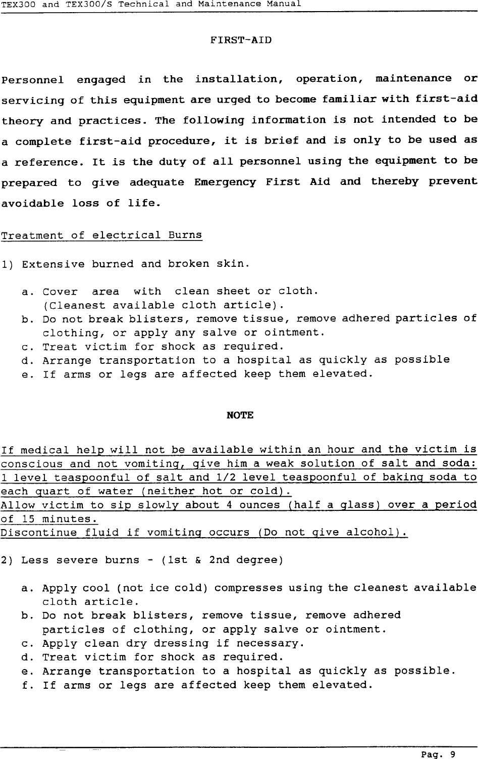
Treatment of Electrical Shock

Chapter 1
DESCRIPTION OF THE XT300 and XT300/S
1.0 INTRODUCTION
This manual contains technical information about the XT300 and XT300/S
exciters. For more simplicity we will always refer to the XT300, unless specified for
clarity.
1.1 GENERAL DESCRIPTION
The XT300 is housed in a 3U, 19” rack-mounting container comprising a num-
ber of interconnected modules mounted internally on the main chassis, facilitating
removal and substitution. The power output control, audio input level control and
analog meter for measurement of the operating parameters, are all mounted on the
front panel. The AC line power, audio input, RF output and telemetry connectors are
mounted on the rear panel.
1.2 ELECTRICAL DESCRIPTION
The XT300 is an exciter working in the 87.5 to 108 MHz band, programmable
in steps of 10 KHz. Its power output is continuously adjustable from 10W to 300W
into a 50 Ohm load. The XT300 incorperates a stereo coder card which guarentees
excellent stereo separation together with low harmonic distortion (only for Stereo
Version). It also accepts two SCA Signals.
A front panel switch allows stereo operation (only for Stereo Version) or
“mono/mpx” operation which excludes the stereo encoder and uses the “right” input
as the mono input and the “left” input as the wideband composite input.
The specifications feature low audio distortion and intermodulation figures
(typically 0.03%) and a high signal-to-noise ratio (typically -80dB).
1.3 METERS AND INDICATORS
The operating parameters of the exciter can be monitored using the analog
multimeter situated on the front panel. The parameter to be measured is selected by
the rotary selector switch.
The frequency control allows frequencies to be selected in steps of 10 KHz.
Three red alarm LEDs indicate VCO unlock, excess VSWR on the output and exces-
sive temerature, and the shutdown condition, programed by a remote command.
Pag. 10
Three green LEDs indicate the presence of +12V, +15V and +28V voltages which are
used to power the various cards inside the exciter. A selector switch allows selection
between Mono/Mpx and Stereo functions and another selector switch provides a
choice of level input signal. Trimmers are provided for adjustment of left and right
channels and a switch allows the stereo subcarrier to be enabled or disabled.
1.4 AUTOMATIC FREQUENCY CONTROL
The operating frequency is governed by a thermally-compensated, reference
oscillator working within a phase locked loop (PLL). The XT300 reaches frequency
lock within a maximum of 30 seconds.
1.5 CONTROL CIRCUITS
The control circuits allow automatic control of the output power (internal and
external), maintaining the chosen power level across the entire operating band. Fur-
thermore, another circuit protects the final stage against excessive VSWR or short
circuits and excessive temperature. Then, there are other protection circuits that act to
limit the maximum output power and to protect the equipment against a power
supply’s overvoltage.
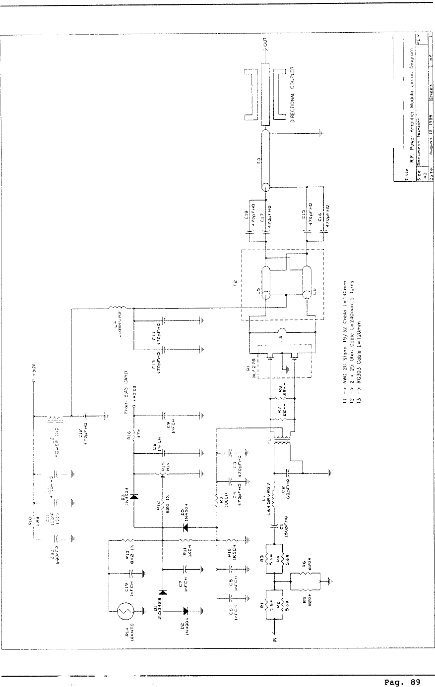
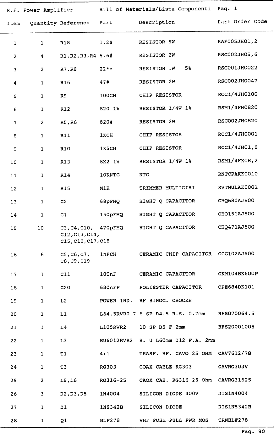
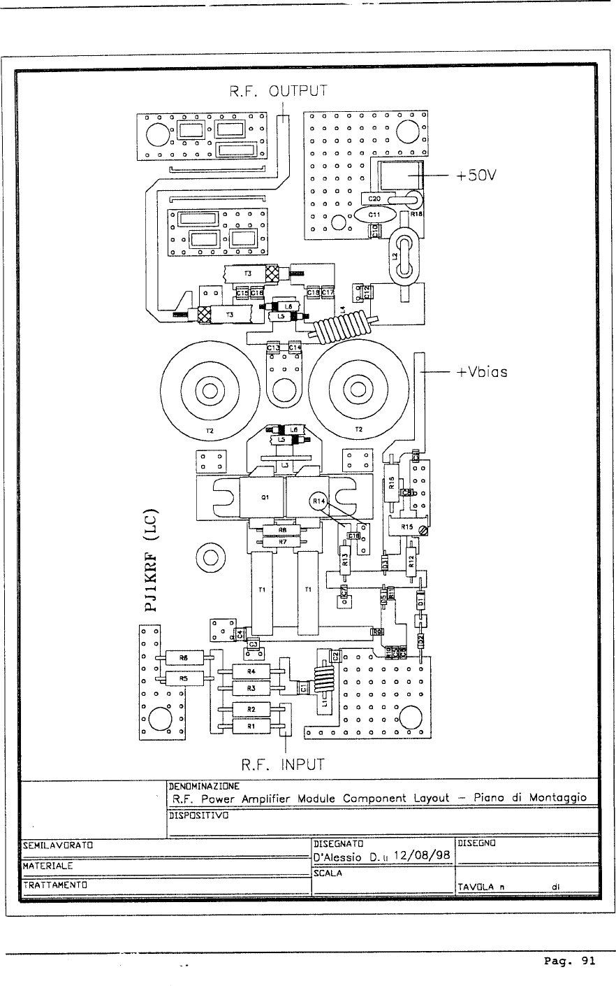
1.6 R.F. POWER AMPLIFIER
The RF amplifier is a broadband design and guarantees an adjustable power
output of 10 to 300 Watts across the entire band. A low pass filter enables the XT300
to be used as a low power transmitter, connected directly to an antenna.
1.7 SPECIFICATIONS
Please refer to Table (A) for the electrical specifications and Table (B) for me-
chanical specifications.
Pag. 11

Pag. 12
ELECTRICAL SPECIFICATIONS
Power supply 117-230V +/- 10 %, 50-60 Hz single phase
Power Consumption approx. 600 W
Cooling Forced ventilation
Frequencies 87.5 to 108 MHz in steps of 10 KHz
Output power adjustable from 10 to 30 W
Automatic Output Level Control Stabilizes the set RF output level
Output Impedance 50 Ohm
Output Connector Standard N-type
Harmonic Suppression > -65 dB
Spurious Signal Suppression > -80 dB
Mono Intermodulation Distortion 0.05 % or less, measured at 1 KHz and 1.3 KHz,
ratio 1:1 at 100 % modulation
Frequency Stability +/- 500 Hz (typically +/- 300 Hz)
from 0 deg to 50 deg C
Modulation Type Direct frequency modulation of the RF oscillator at the
fundamental frequency
Frequency Deviation +/- 75 KHz nominal
Harmonic Distortion < 0.05 % (typically 0.01 %)
FM Signal-to-Noise Ratio > 75 dB mono, > 70 dB stereo measured with 75 KHz
deviation in the 30 Hz to 15 KHz band RMS.
Residual AM (asynchronous) Approx. 0.05 % + 65 dB RMS
TABLE A
Pag. 13
Residual AM (Synchronous) 0.1% = 60dB
Pre-emphasis 50uS +/- 2% 0r 75 uS +/- 2% selectable
Audio Input Impeadance 10 KOhm balanced or 5K Ohm unbalanced
(600 Ohm on request)
Audio Input Level Selectable from -9 to +6 dBm in five steps
Continuous from -12 to +9 dBm
Audio Frequency Range 30-15000 Hz, MONO input
30-100000 Hz, MPX input
Audio Input Filter > 45 dB at 19 KHz (Mono)
> 40 dB from 20 KHz to 100 KHz
Mono Frequency Response +/-0.3 dB from 30 Hz to 15KHz
MPX Frequency Response +/-0.5 dB from 30 Hz to 75KHz
Stereo Separation > 45 dB (typically 50 dB)
Pilot Tone Frequency 19 KHz +/- 1 Hz
Pilot Tone Level -20 dBm adjustable
Number of SCA inputs 2
SCA Input Impedance 1 KOhm unbalanced
SCA Input Level 0 dBm for +/- 7.5 KHz of deviation
SCA Input Response +/- 0.5 dBm from 40 KHz to 100 KHz

Pag. 14
TABLE B
MECHANICAL SPECIFICATIONS
Rack dimensions 483.0 mm (19.0”) W
132.5 mm (5.20”) H
500.0 mm (19.7”) D
Operating temperature from -10 deg C to 45 deg C
Humidity 95 % max. non-condensing
Weight 22 Kg

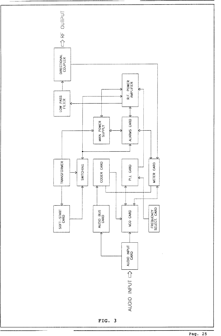
2.1 INTRODUCTION
This section describes, in detail, the operating theory behind the XT300. To aid understand-
ing, the unit has been subdivided into blocks, each of which is fully described below. The block
diagram is shown in Fig. 3
2.2 POWER SUPPLY
This circuit comprises a board, mounted on a heat sink, which is fixed to the central part of
the lower section of the unit. The power supply generates the various modules that make up the
XT300. The transformer has a selectable input from 110V to 240V and three outputs:
A. 30/0/30V (9A), B. 36V (0.5A), and C. 20V (1A).
This power supply is composed of two main parts: after having undergone filtering for mains-
borne interference, the supply is transformed into four lower voltages, rectified, smoothed and
stablized to the following values: +12V, +15V +15 variable and +50V to obtain the higher efficiency
switching power supply (85-90%).
The +15V supplies the encoder mixer, the PLL card, the VCO card, the meter card and the
alarms card. The +12V supplies the fan . The +15V variable supplies the input of the RF power
module amplifier driver (BLF244) and the 50V supplies the final power stage (BLF278).
The variable voltage of the final stage driver is controlled by the PWR ADJ control which
determines the RF power output of the exciter. The automatic control of the output power guarantees
the power level set by the PWR ADJ control right across the frequency range and independently of
the other variables such as temperature, load variations etc.
The system works by comparing the value set by the PWR ADJ control with the actual power
output of the unit and compensating accordingly.
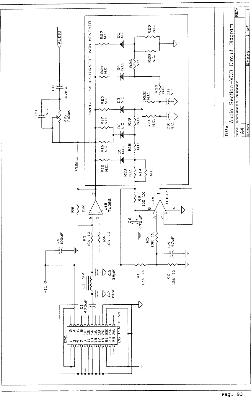
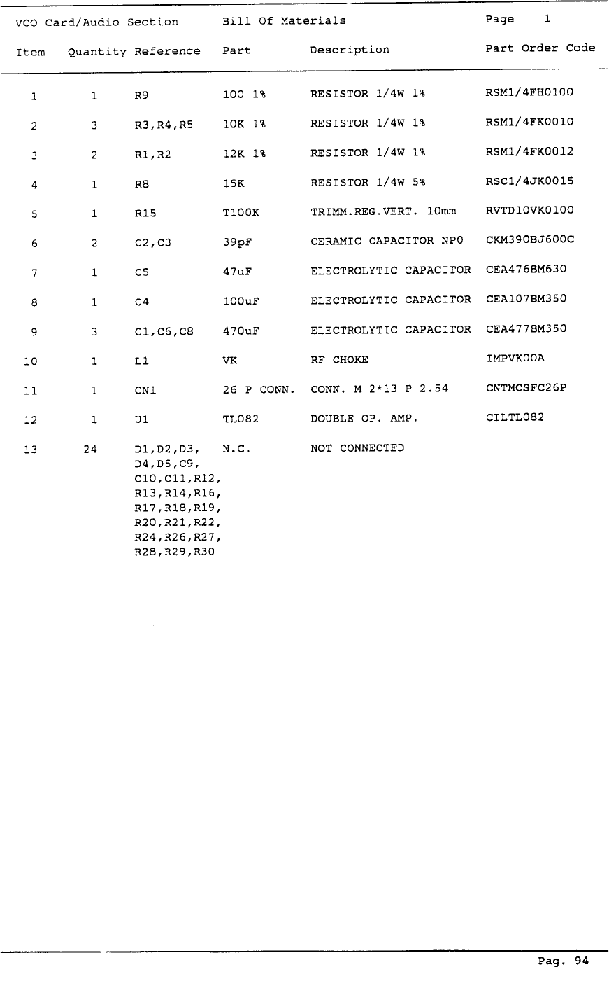
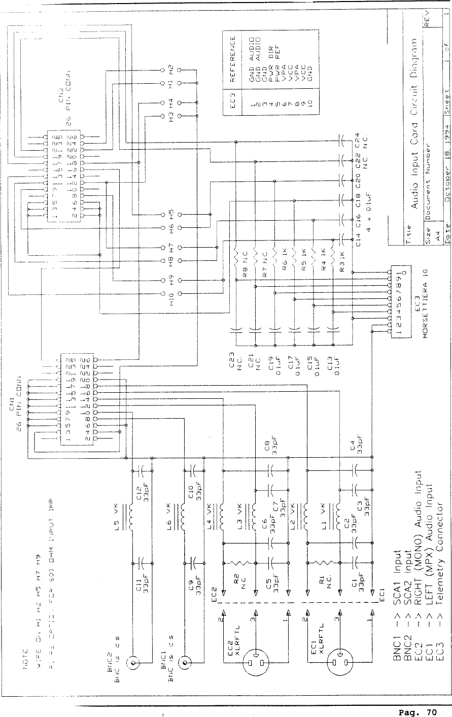
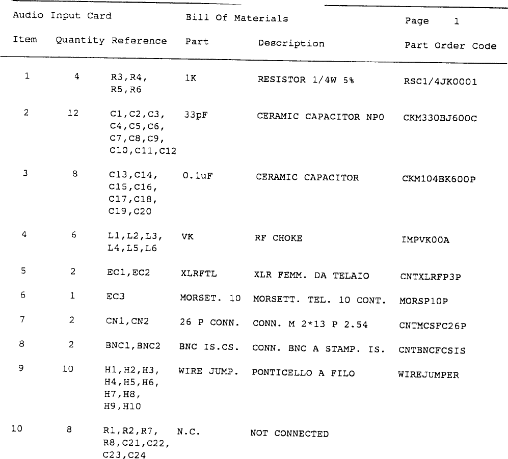
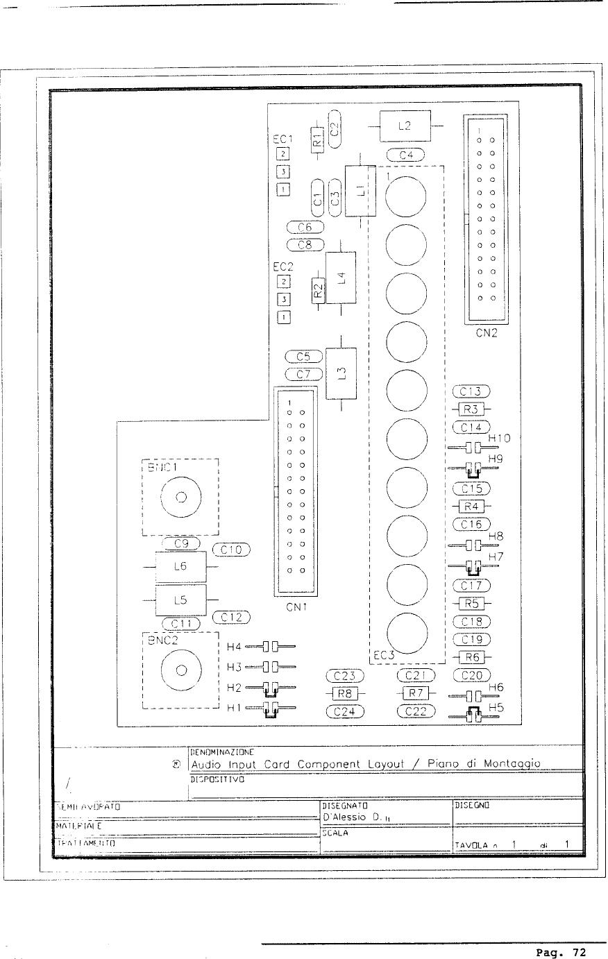
2.3 AUDIO INPUT CARD
This card is situated on the rear panel of the exciter. The card filters all audio signal inputs to
the unit, removing RF interference, before supplying them to the encoder mixer or mono/mpx card.
The main operating parameters of the exciter are available for remote monitoring via the telemetry
connector.
2.4 STEREO CODER CARD (only for Stereo Version)
This card is situated in the lower part of the unit.
Pag. 15
ELECTRICAL DESCRIPTION
Chapter 2
The card can function either as a stereo encoder or as a simple mixer for the various
audio inputs. The function may be selected by a control situated on the front panel.
In the stereo encoder mode, the 19 KHz pilot tone is derived from a quartz crystal
reference oscillator. So too is the sampling frequency which allows the L and R sig-
nals to be separated from the multiplexing signal. Plus the suppresion of the 38 KHz
frequency. The level of the left and right signals are set by the corresponding selector
situated on the front panel. The signals are filtered at 15 KHz and pre-emphasized (50
uS CCIR, 75 uS FCC) before being sent to the multiplexing circuit. The audio signals
from the two SCA inputs are mixed in to provide the output. In the mixer mode
(Mono/Mpx) the stereo encoder is bypassed, the right input accepts a mono signal and
the left input accepts a multiplex signal up to 100 KHz. The SCA inputs remain un-
changed. Three rectifiers allow the peak levels of the two inputs “Left/MPX” and
“RIGHT/MONO” to be displayed on the analog meter, and provide the audio detector
circuit with the deviation level.
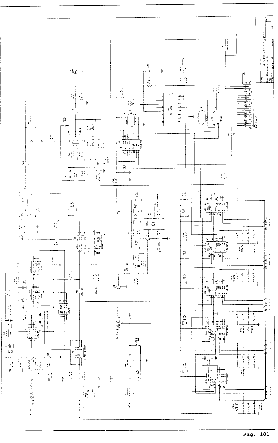
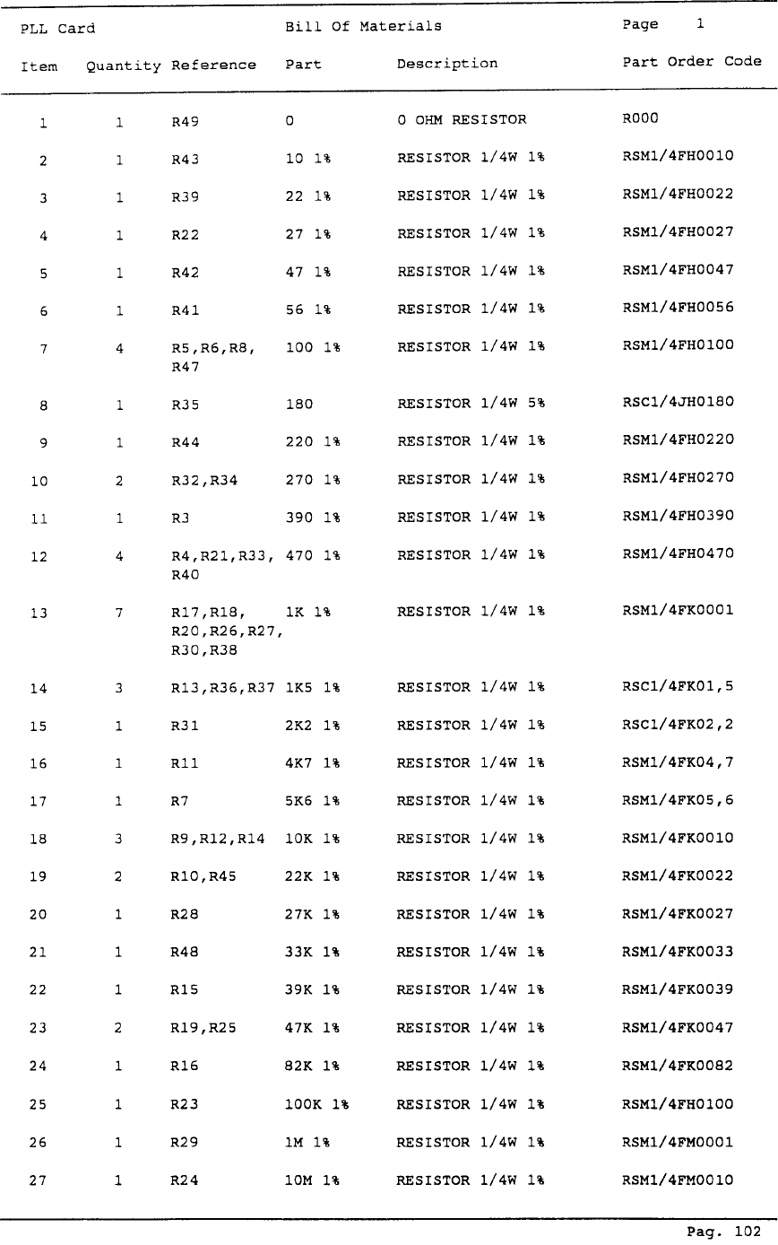
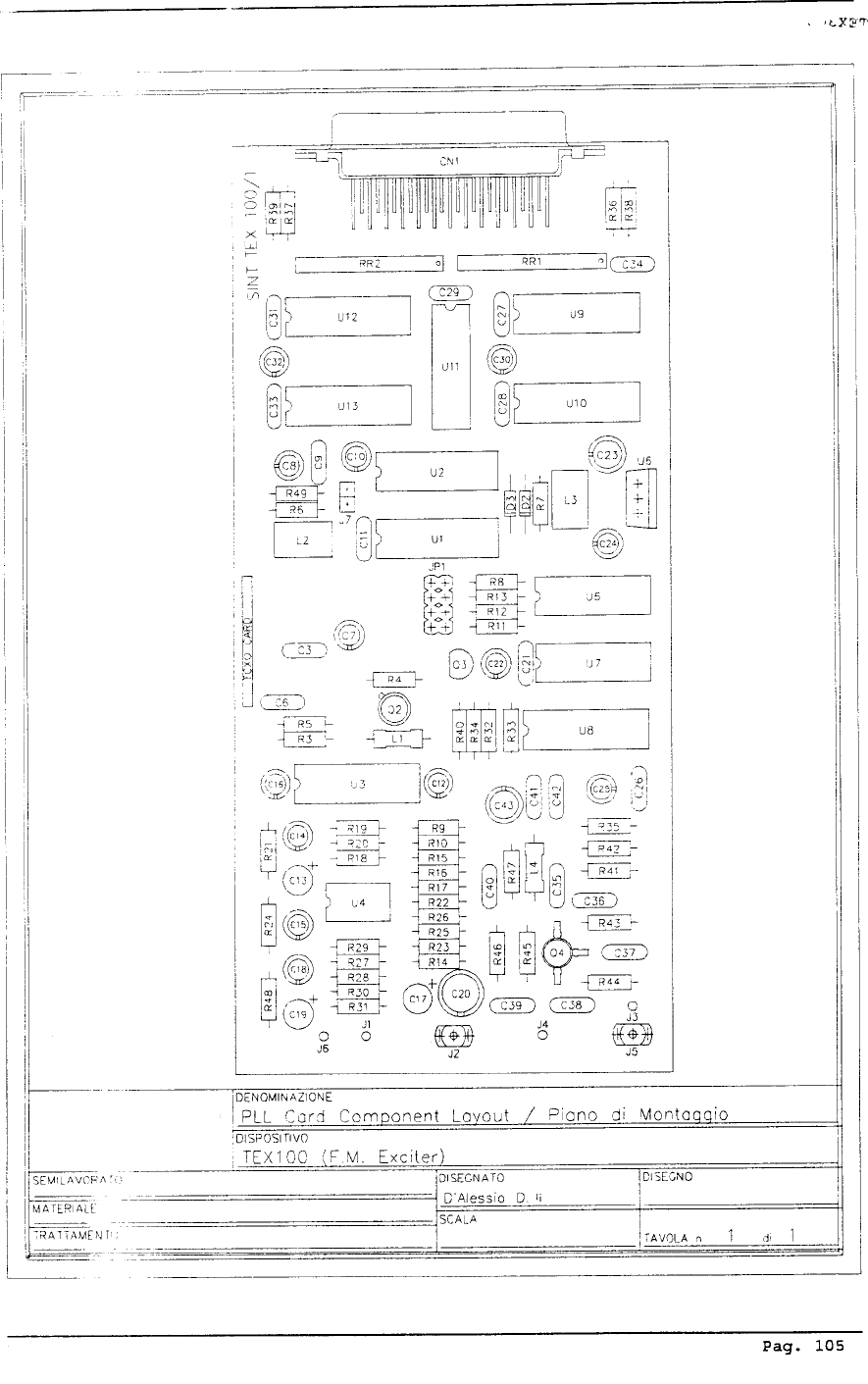
2.5 PLL CARD
The PLL card is situated internally, in the upper part of the unit. The circuit
includes a reference crystal oscillator (optional high stability), a logic section that
includes the frequency dividers and comparator. The reference crystal oscillator gener-
ates a 4 MHz frequency that is divided to generate a fixed 1 KHz signal. This signal is
compared to the operating frequency generated by the VCO divided based on the
frequency set on the contraves board. An indicator situated on the front panel signals
the “unlocked” condition. The comparator output (AFC signal) is sent to the varicap
diodes situated on the VCO card.
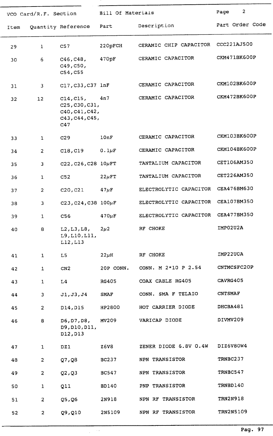
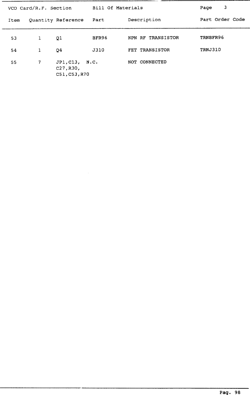
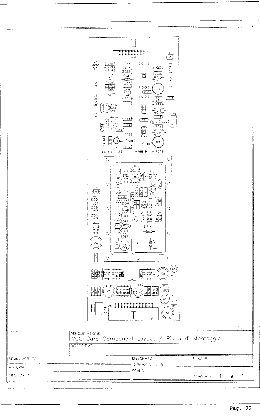
2.6 VCO CARD
The VCO card is situated internally, in the upper part of the unit. This module includes
an audio input stage at low frequency, a voltage controlled oscillator (VCO) and driver
stage. The audio signal supplied by the encoder mixer is amplified and then injected
into the VCO to provide class F3 modulation. The voltage controlled oscillator (VCO)
generates the signal on the frequency set on the contraves. This signal is amplified to
300mW level (25dBm) to drive the final stage and sent to the PLL circuit situated on
the PLL card. The operating frequency generated by the VCO is divided down before
being compared to a reference frequency, generated by a high stability oscillator (stan-
dard 5 ppm).
Pag. 16
The error voltage is filtered and used to compensate the VCO frequency and
guarantee its stability. A trimmer is present on this card for adjustment of deviation.
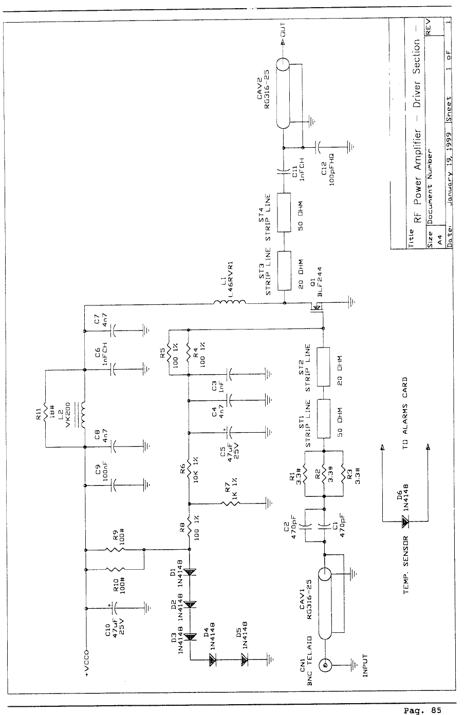
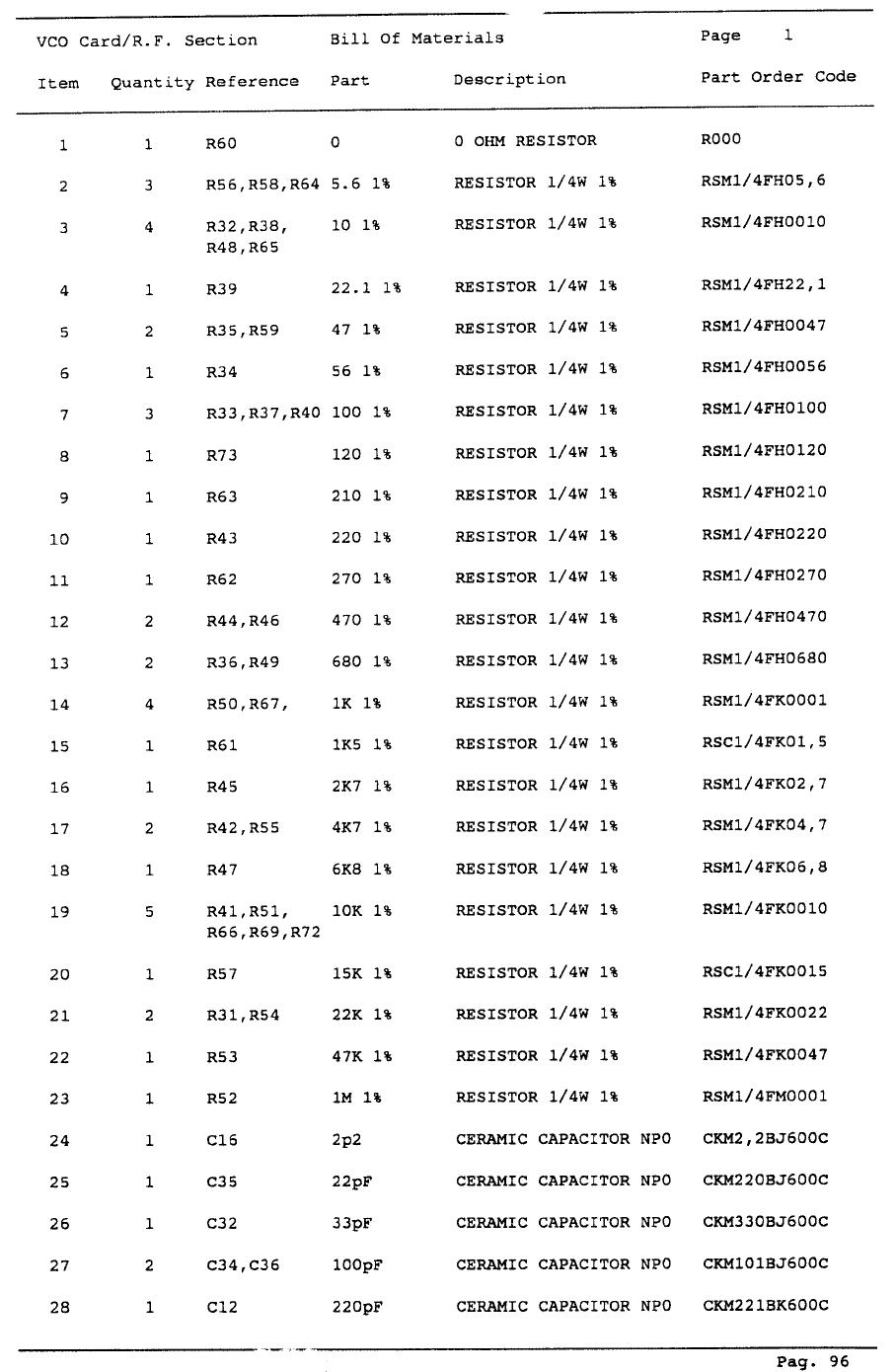
2.7 RF POWER AMPLIFIER
The final power stage is mounted on a heat sink to dissipate waste heat and is en-
closed in a totally screened metal container, fixed to the upper-middle part of the
central section of the unit. The RF signal coming from the stereo decoder or Mono/
MPX at a power level of about 300mW, reaches the driver stage (BLF244) and is
amplified to a level from about 300mW to 8W before being further amplified by the
final stage (BLF278) to a level of up to 300W. The resultant signal is then filtered by a
low-pass filter which removes any harmonic content. A directional coupler allows the
direct and reflected power levels to be measured and displayed on the analog multim-
eter and fedback to the power supply for automatic control of the output power (see
power supply description). A BNC connector situated on the rear panel provides a
power signal at -60db of the amplifier output power.
2.8 METER CARD
This card is situated centrally on the front panel. The card receives direct and
reflected power signals from the power supply which, in turn, come from the final
power stage. The stereo encoder card supplies deviation and left and right signal lev-
els. These signal levels are then displayed on the analog meter according to the posi-
tion of the rotary selector situated on the front panel.
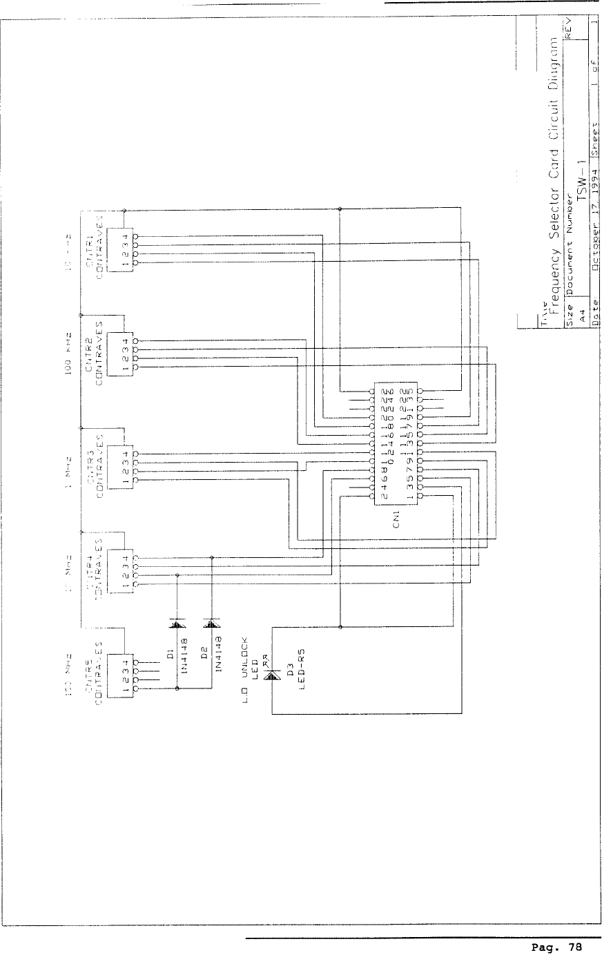
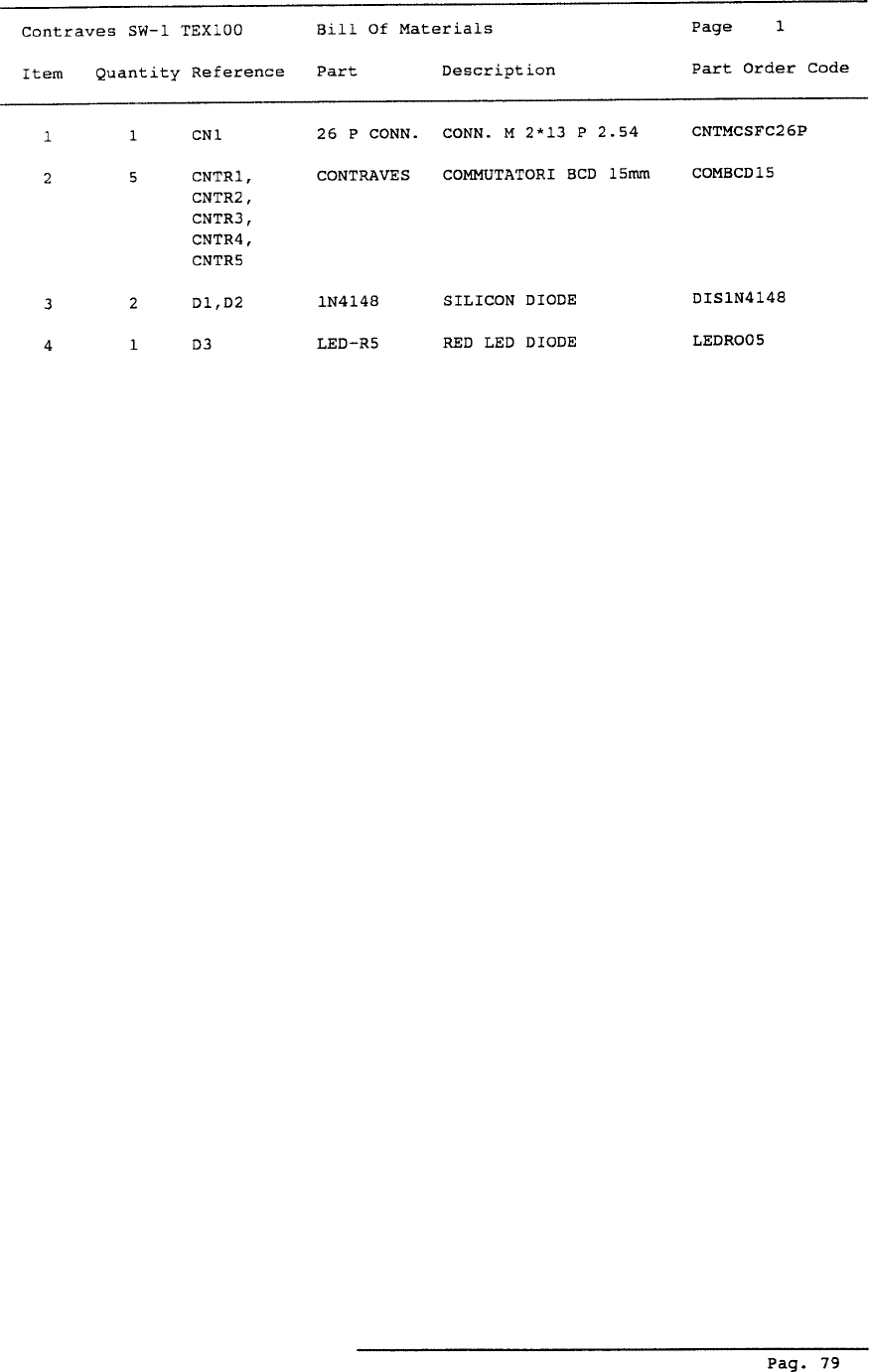
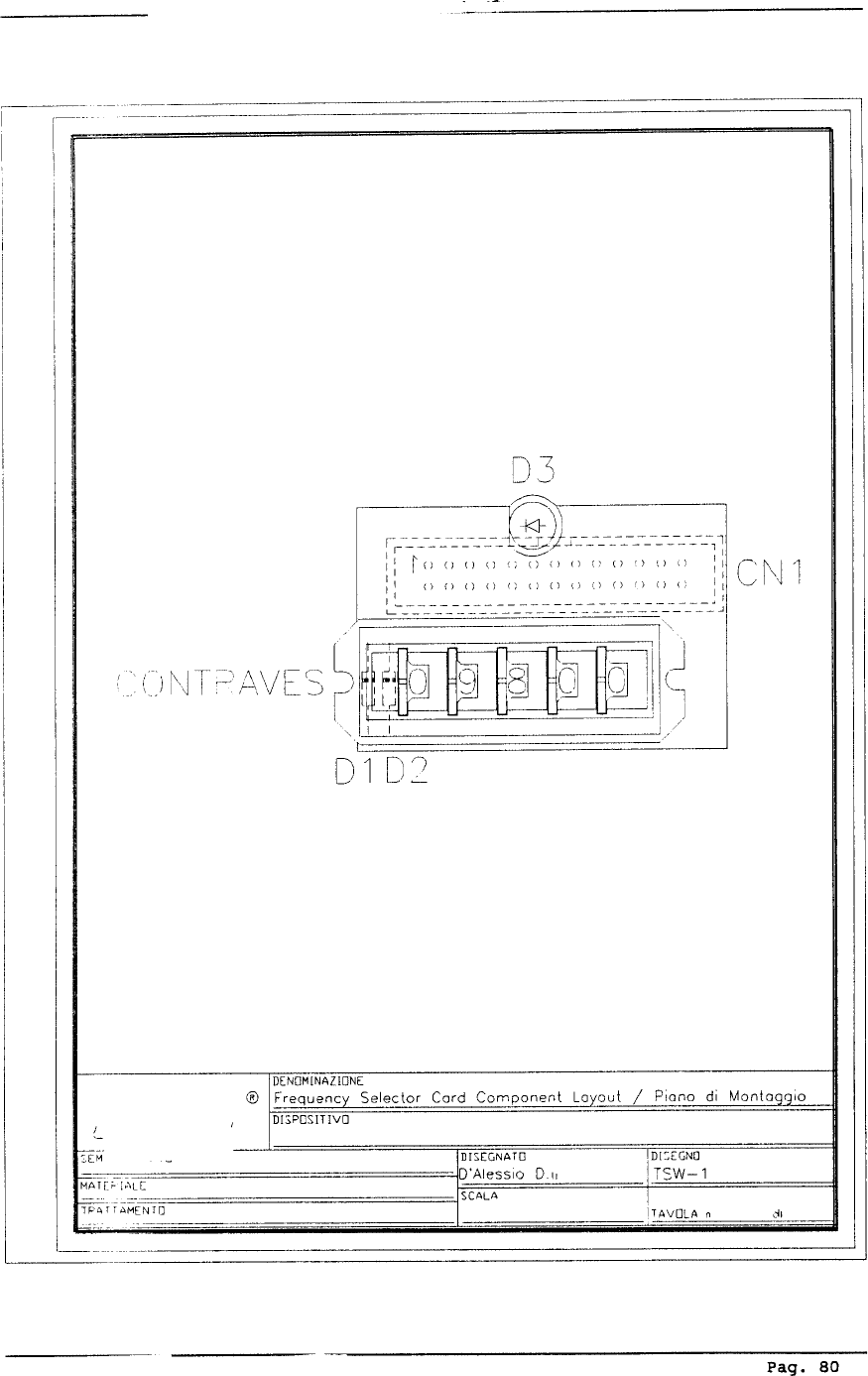
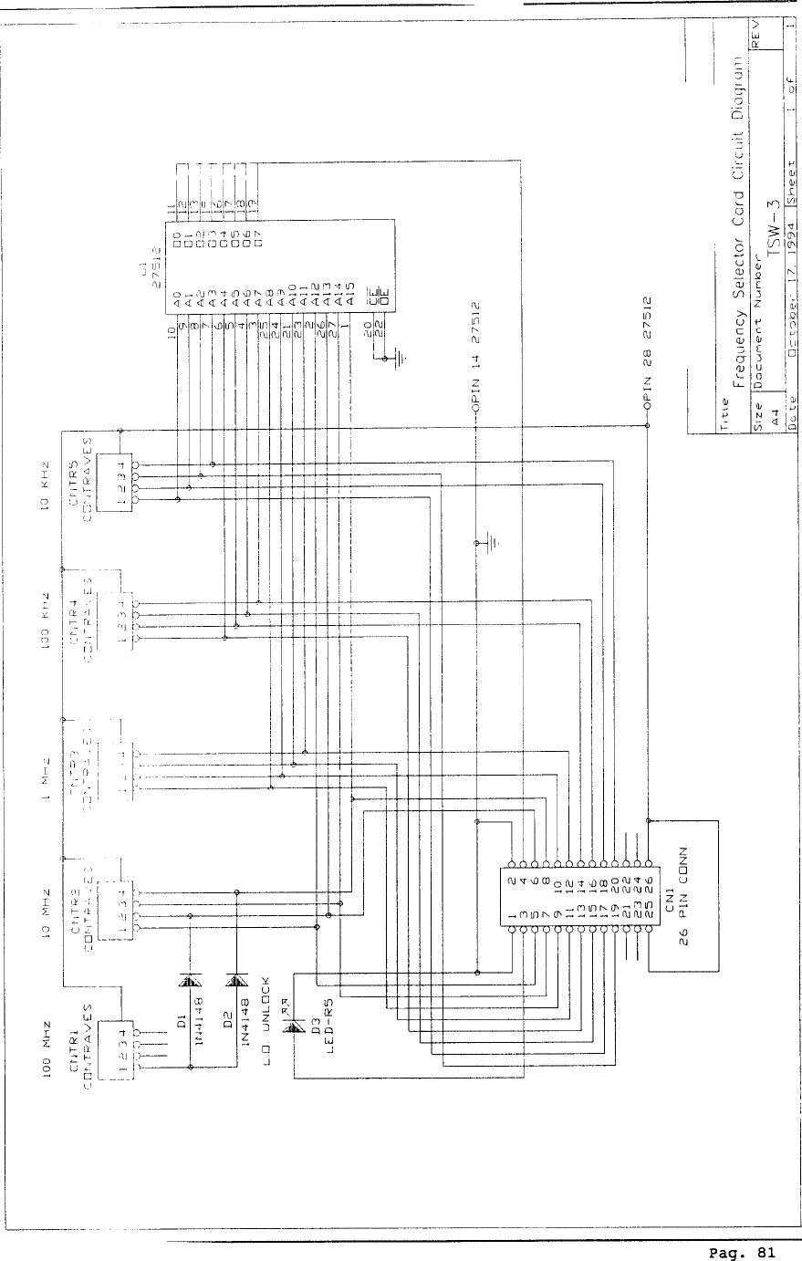
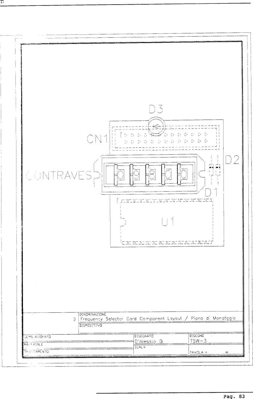
2.9 FREQUENCY SELECTOR CARD
This card is located on the left-hand side of the front panel. The operating fre-
quency selected by the frequency control is represented by a signal which is supplied
to the frequency dividers that form part of the PLL circuits found on the PLL card.
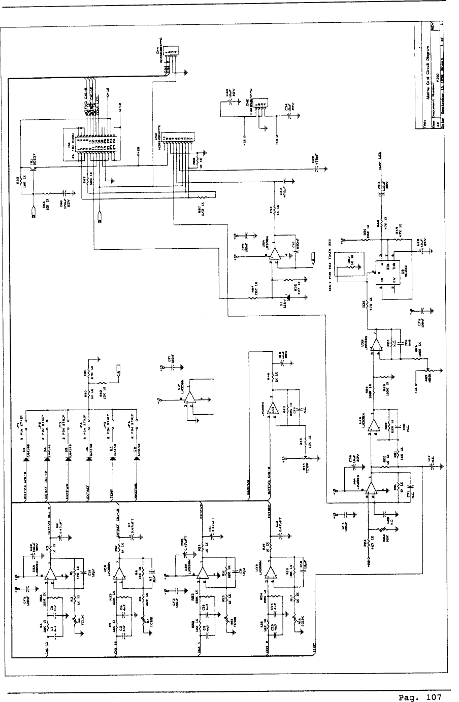
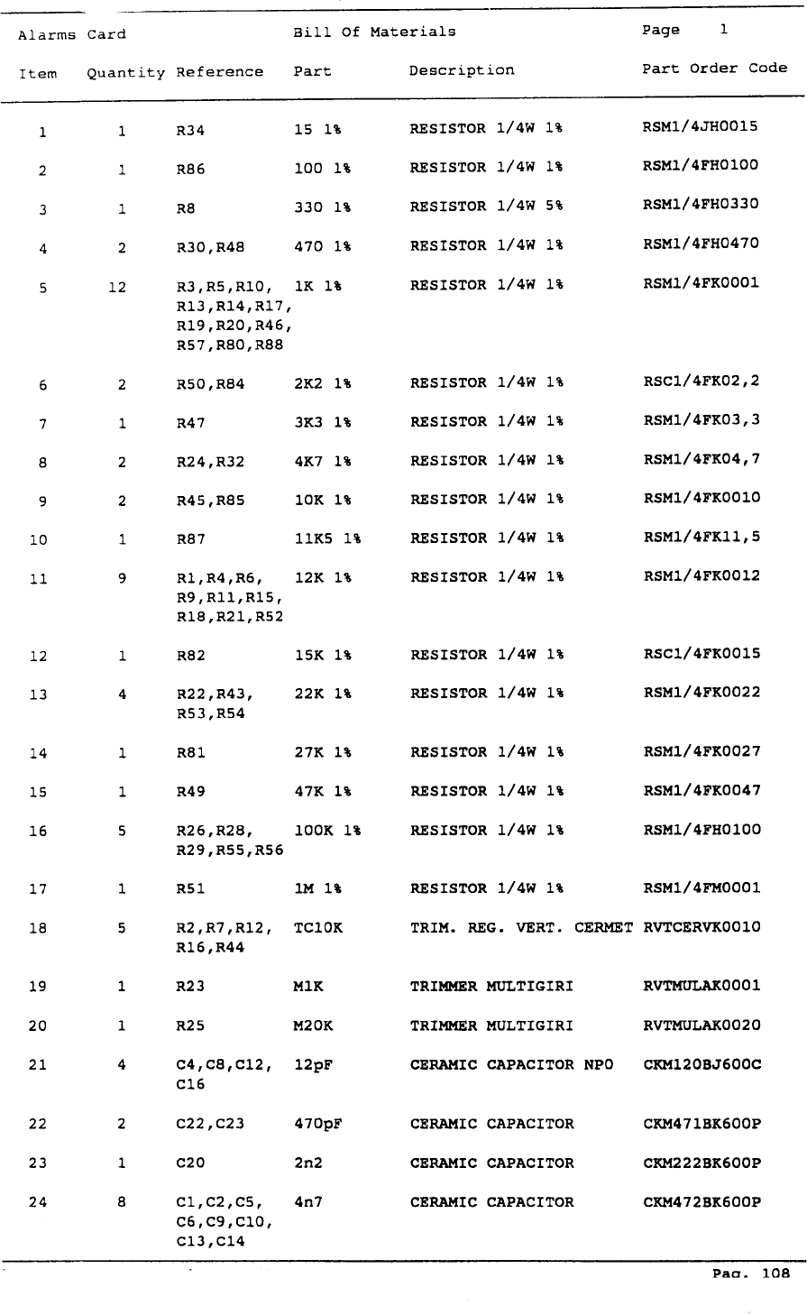
2.10 ALARMS CARD
This card is fixed in the lower part of the unit. This circuit allows 7 adjustments
via trimmers, the threshold of the external and internal output level, internal and exter-
nal VSWR level, temperature and to preset the maximum value of the output power. In
case of a fault there is no automatic reset, because the transmitter automatically re-
duces the output power to continue transmitting without interruption, even if at mini-
mum power.
Pag. 17
2.11 SOFT START
The soft start is mounted on a board placed on the front side of the transmitter.
The circuit eliminates the current spikes generated by the transformer when it is pow-
ered.
2.12 MONO/MPX CODER CARD (Mono Version)
This card is located in the lower part of the unit. The Mono/MPX card is an
Audio Mixer at four inputs: two balanced (Mono and MPX) and two unbalanced
(SCA1 and SCA2). Mono and MPX input level can be set through decade
thumbwheel switches on the front panel, on 5 fixed positions and on a variable posi-
tion from -12 dBm to +9 dBm (preset at 0 dBm). It’s possible to set the pre-emphasis
value at 50uS, 75uS or linear. Then, it’s possible to insert or remove a low pass filter
at 15KHz.
2.13 CLIPPER CARD
This card is attached with a sandwich structure on the coder card and is acces-
sible from the lower part of the equipment. Its function is to limit drastically any audio
signal that exceeds a prefixed threshold. Therefore, it’s used to avoid any type of over-
modulation which exceeds maximum peak permitted of +/- 75 KHz.
Pag. 18
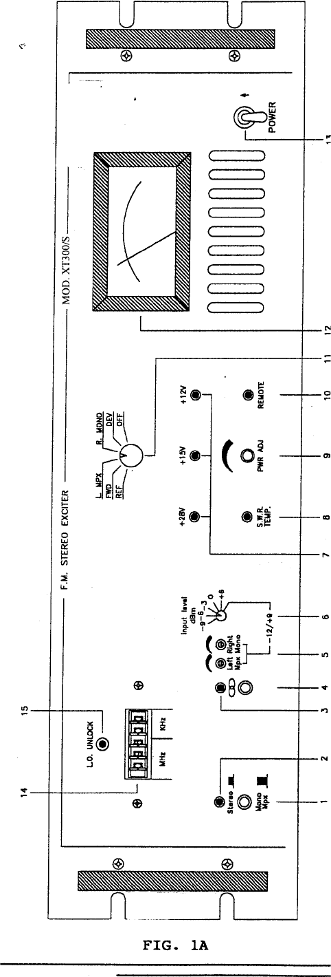
FRONT PANEL STEREO VERSION VEIW DESCRIPTION (FIG. 1A)
1 STEREO/MONO-MPX Selects STEREO or MONO/MPX operation
2 STEREO LED Indicates the operation of the stereo
encoder
3 19KHz LED Indicates the 19KHz pilot tone presence
4 MODE SELECTOR Button in: STEREO OPERATION MODE
PILOT TONE PRESENT
Button out: MONO OPERATION MODE
PILOT TONE ABSENT
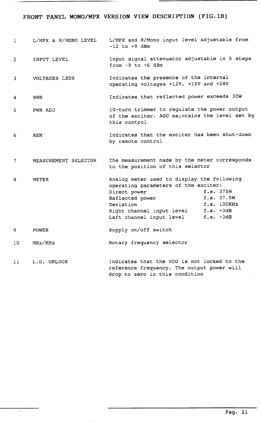
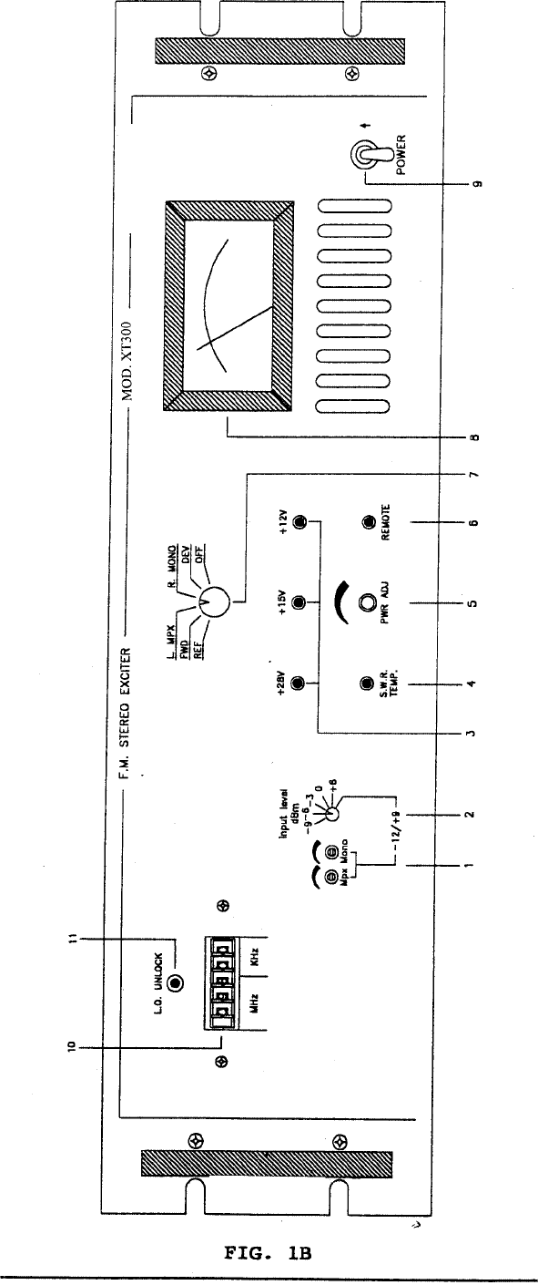
5 L/MPX &R/MONO LEVEL L/MPX AND R/MONO input level adjustable
from -12 to +9 dBm; this is possible if the
input level switch is completely turned clock
wise
6 INPUT LEVEL Input signal attenuator adjustable in 5 steps
from -9 to +6 dBm
7 VOLTAGE LEDs Indicates the presence of the internal operating
voltages +12V, +15V and +28V
8 SWR Indicates that reflected power exceeds 30W
9 PWR ADJ 10-turn trimmer to regulate the power output of
the exciter. AGC maintains the level set by this
control
10 REM Indicates that the exciter has been shut-down
by remote control
11 MEASUREMENT SELECTOR The measurement made by the meter corresponds to the
position of this selector
12 METER Analog meter used to display the following operating
parameters of the exciter:
Direct power f.s. 375W
Reflected power f.s. 37.5W
Deviation f.s. 100KHz
Right channel input level f.s. +3dB
Left channel input level f.s. +3dB
13 POWER ON/OFF switch
14 MHz/KHz Rotary frequency selector
15 L.O. UNLOCK If ON indicates that the VCO is not locked to the
reference frequency. The output power will drop to zero
in this condition
Pag. 19
Pag. 20
Pag. 22
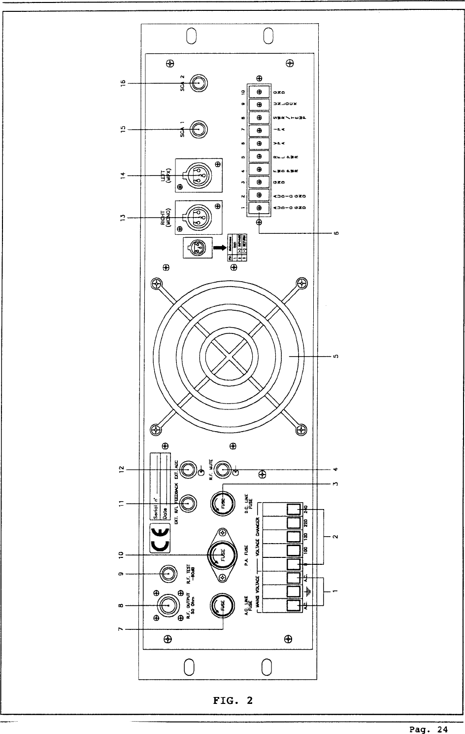
REAR PANEL View Description (Fig, 2)
1 MAINS VOLTAGE SOCKET Mains Voltage Socket
2 VOLTAGE CHANGER Mains Voltage Changer:
Connect: 0-100V for 100V A.C. Input
Connect: 0-120V for 120V A.C. Input
Connect: 0-220V for 220V A.C. Input
Connect: 0-240V for 240V A.C. Input
3 D.C. LINE FUSE Protection for D.C. line R.F. module
4 R.F. MUTE BNC connector. Connecting the center conductor to
ground will cause the RF output power level to drop to
zero and stay there until the short is removed. When
used with a Bext, Inc. amplifier, this connector should
be connected to the “REMOTE” output of the power
amplifier.
5 FAN Fan-assisted cooling for the power stage and power
supply
6 TELEMETRY TERMINALS 10 Pin Telemetry card
1-2 Audio GND
3-10 GND
4 Forward power
5 Reflected power
6VPA
7IPA
8 SWR Alarm/Temp
9 Unlock alarm
7 A.C. LINE FUSE Protection fuse for A.C. line
8 R.F. OUTPUT N-type connector, 50 Ohm
9 R.F. TEST POINT -60 dB output referred to the output level
10 P.A. FUSE Protection fuse for the Switching Power Supply
11 EXT. RFL FEEDBACK BNC connector, external Reflected Feedback Input
12 EXT. AGC BNC connector, external AGC input
13 RIGHT (MONO) BNC connector for FCC unbalanced version: Cannon
XLR for CCIR version with balanced input
14 LEFT (MPX) BNC connector for FCC unbalanced version: Cannon
XLR for CCIR version with balanced input
15 SCA1 BNC connector, unbalance SCA1 input
16 SCA2 BNC connector, unbalance SCA2 input or output
(internally selectable) for pilot tone (i.e. for RDS
encoder)
Pag. 23
BOTTOM VIEW DESCRIPTION (PHOTO 1)
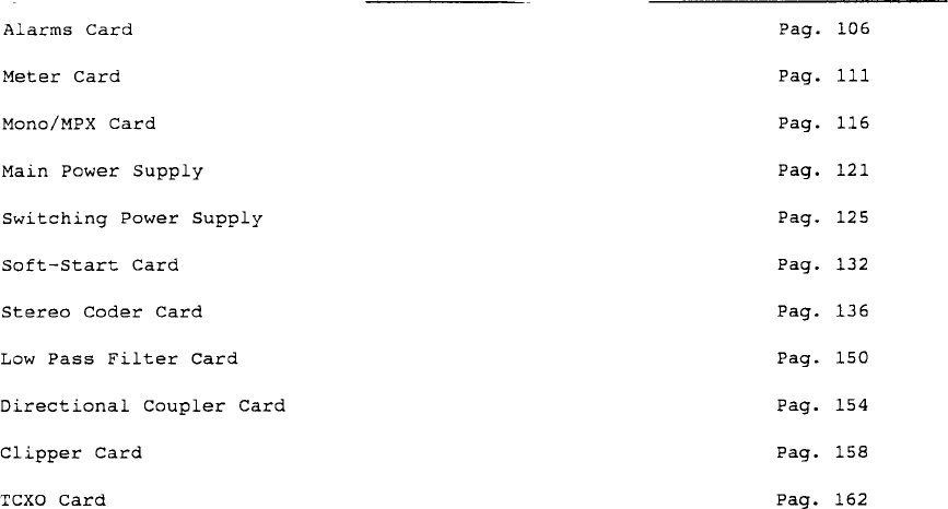
1 Meter card
2 Stereo coder card (for Stereo Version)
Mono/MPX card (for Mono Version)
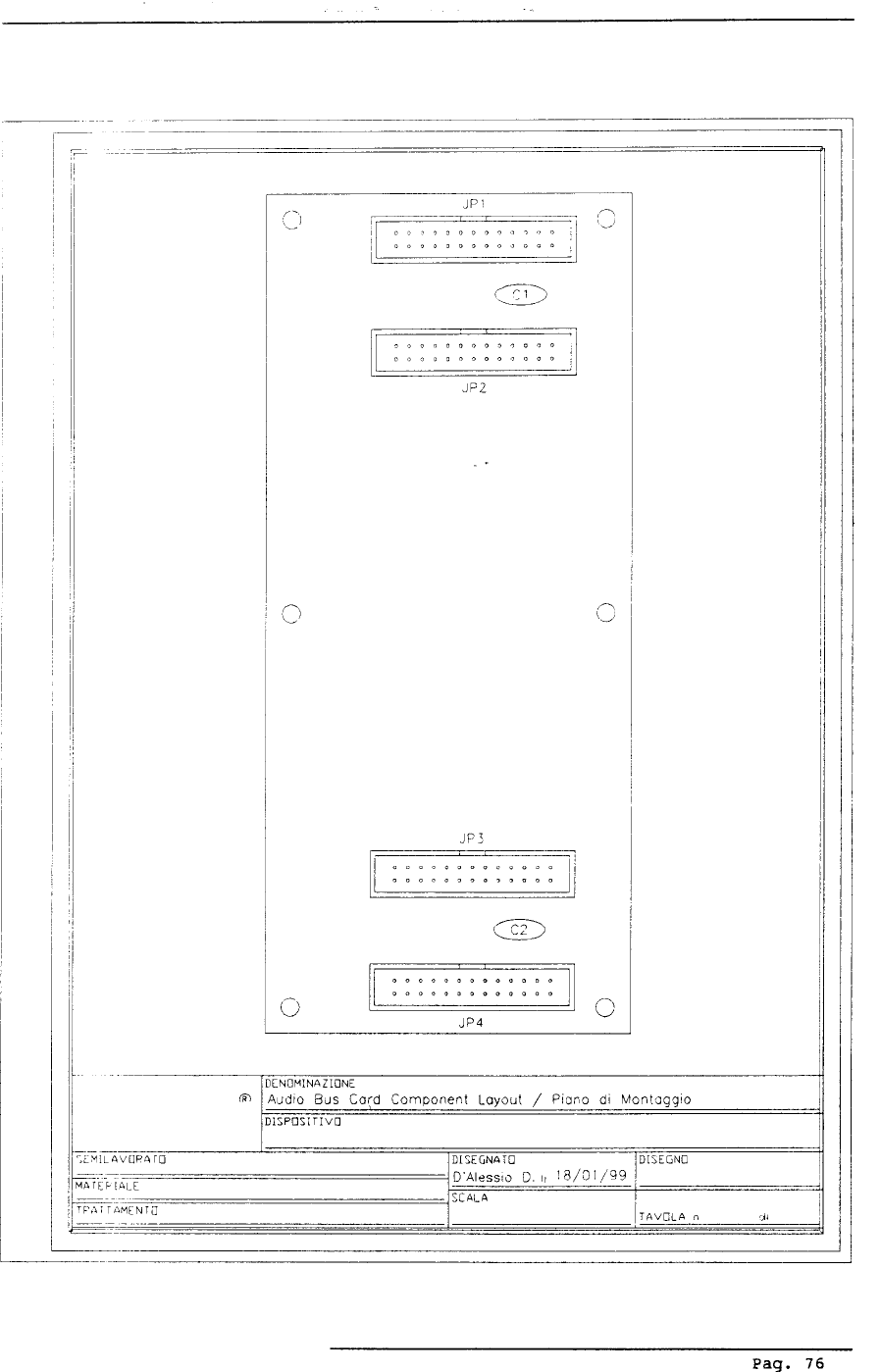
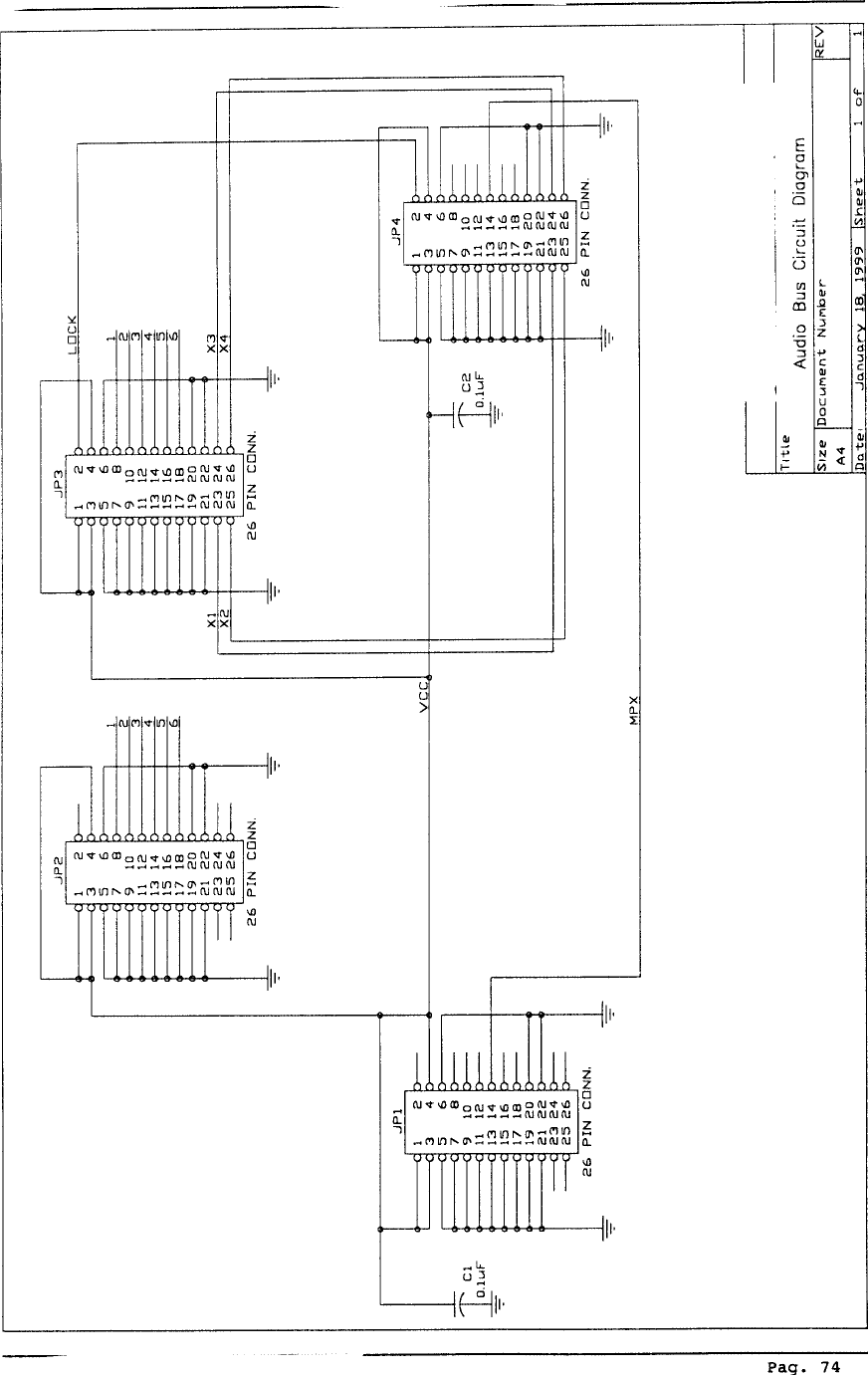
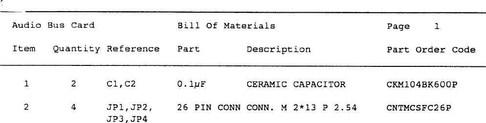
3 Audio bus card
4 Power supply card
5 Alarms card
6 Audio input card
Pag. 26

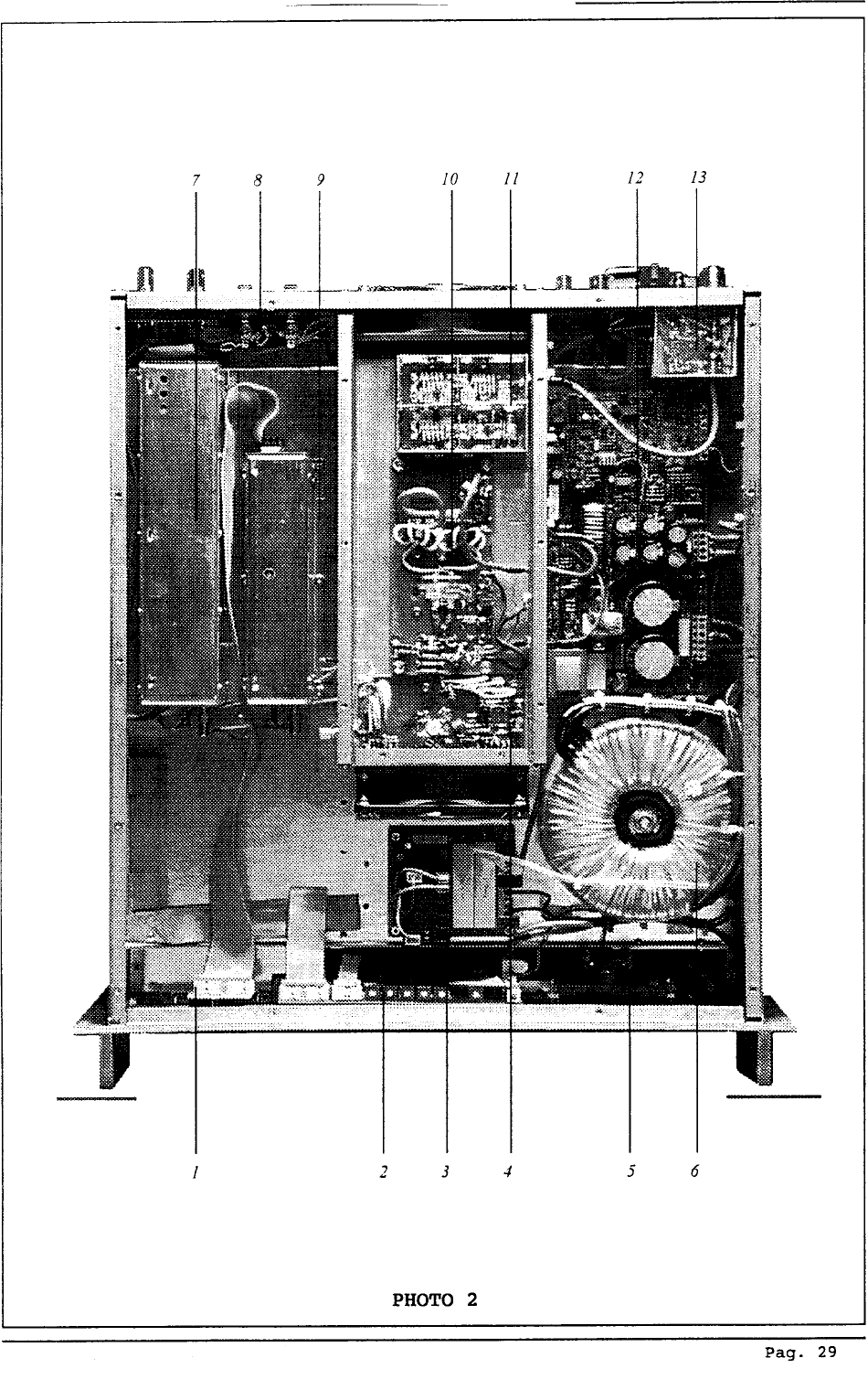
UPPER VIEW (PHOTO 2)
1 Frequency Selector card
2 Meter card
3 Soft-Start card
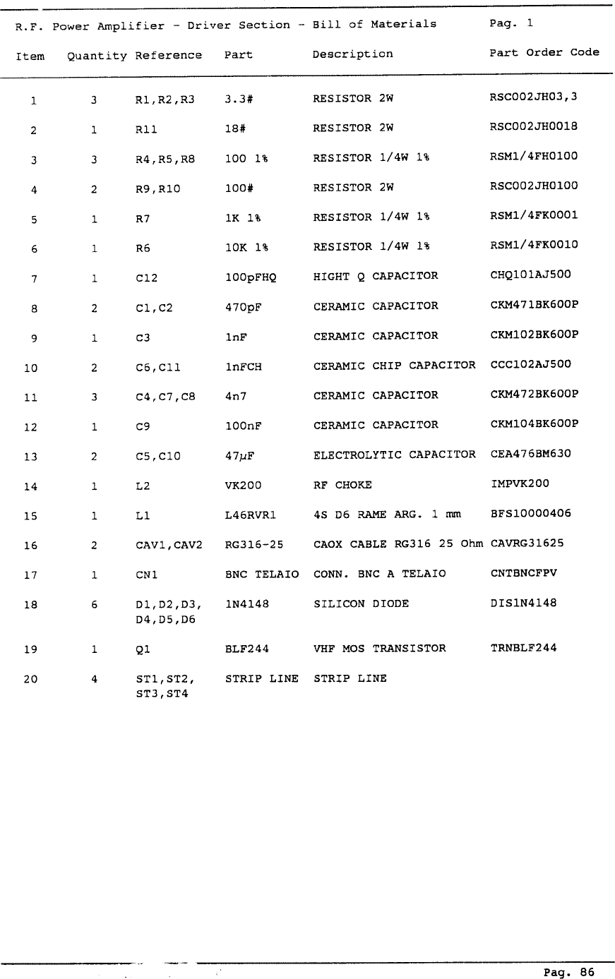
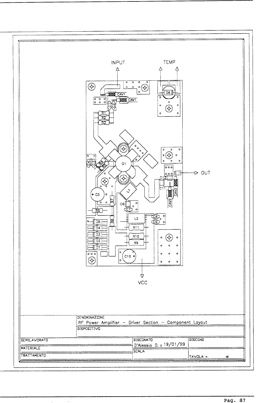
4 R.F. Power Amplifier- Driver Stage
5 Analog Meter
6 Transformer
7 VCO
8 Audio Input card
9 PLL
10 R.F. Power Amplifier-Final Stage
11 Low Pass Filter
12 Switching Power Supply
13 Directional Coupler
Pag. 28

CHAPTER 3
INSTALLATION
3.1 INTRODUCTION
This chapter contains the information required for installation of the XT300 exciter and for
preliminary checks.
3.2 UNPACKING
Remove the unit from its packaging and before any other operation, check for damage that
the unit may have suffered in transit and check to be sure all front panel controls are functioning.
3.3 INSTALLATION
1) Check that the line voltage selector is correctly set for the local supply. Check also that the
A.C. Line Protection Fuse (Fig.2 Item 7) is mounted on the rear panel. The currrent sizes of
the fuses are as follows:
220-240V 6.3A
100-120V 12.5A
2) Now ensure that the PWR ADJ control (Fig. 1A Item 9 or Fig. 1B Item 5) is rotated fully
counterclockwise, using a small screwdriver (the pot is a ten turn pot so care should be taken
to verify the minimum position). Units are normally shipped with this control at minimum.
WARNING: When the unit is switched on with the control at its minimum posi-
tion, power output is about 10W.
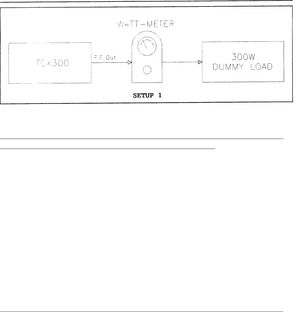
3) Connect a dummy load with a power rating of at least 300W continous to the R.F. output,
situated on the rear panel of the unit. It is advisable to connect a bypass wattmeter in series
with this load in order to verify the accuracy of the units own internal wattmeter (see setup 1).
4) Connect a switch, via a cable, to the R.F. Mute connector (Fig. 2 Item 4) on the rear panel so
that the switch is able to short the central conductor to its ground. Leave the switch in the
short-circuit position.
5) Switch the unit’s ON/OFF switch (Fig. 1A Item 13 or Fig. 1B Item 9) to the OFF position.
Pag. 30
6) Connect the line cord. (Fig.2 Item 1)
(It is essential that the unit be properly grounded to ensure both the safety of the
operator as well as the correct functioning of the equipment.)
7) Switch the power switch (Fig. 1A Item 13 or Fig 1B Item 9) to the ON position and check
that the three green internal voltage LEDs, (Fig. 1A Item 7 or Fig. 1B Item 3) and the red
unlock LED (Fig. 1A Item 15 or Fig. 1B Item 11) are all on. Select the desired operating
frequency using the corresponding selector. The red UNLOCK LED should switch off within
30 seconds, indicating that the oscillator has locked onto the operating frequency. The
frequency selector comprises five figures of which three to the left of the decimal point
represent (from left to right) hundreds MHz, tens MHz, and MHz. The two figures to the
right of the decimal point represent (from left to right) hundreds of KHz and tens of KHz.
EG: 098.45= ninety eight megahertz and four hundred and fifty kilohertz.
EG: 103.94= one hundred and three megahertz and nine hundred and forty kilohertz.
Furthermore, if a frequency is selected beyond the two limits of the 87.5-108 band, the
amplifier will continue to work even though the displayed frequency no longer corresponds
to the operating frequency of the unit.
Transmitting outside the legal band (87.5-108 MHz) is an offense and may lead to prosecution.
8) After having verified that the UNLOCK LED is off and that the unit is therefore locked to the
selected operating frequency, switch the switch connected to the REMOTE connector so as to
remove the short circuit between the center conductor and the ground. The R.F. output is now
enabled and should correspond to a power level of about 10W. To check this reading, select
FWD on the meter selector and read the power from 375W FSD scale.
Pag. 31

9) Using a small screwdriver, rotate the PWR ADJ control clockwise; the power output should
increase progressively to a maximum of 300W. Check the value with the bypass wattmeter
which should be within +/- 10% of the front panel meter.
10) With the power output at 300W, select a new operating frequency well away from the current
value.
Eg: 107 MHz: the UNLOCK LED should switch to on and the power output
should fall to zero at the same time. Only when the UNLOCK LED switches off
(unit locked to new frequency) should the power output resume its previous
level.
11) Automatic power control check.
It is advisable to start this procedure with the operating frequency set to 87.50 MHz. When
locked to this frequency, the PWR ADJ control should be adjusted for an output power of
150W. Now, with no further adjustment of the PWR ADJ control, change the operating
frequency in steps of 4-5 MHz, ensuring that the output power remains constant at 150W.
12) SWR alarm check.
For this test, adjust the PWR ADJ control for a power output of 10W. Disconnect the output
load and check that the SWR LED lights. Now adjust the PWR ADJ control to check that the
unit switches on again at a reflected power level of about 10% of the output power. Turn the
PWR ADJ control for maximum power and check that the reflected power does not exceed
30W. Reconnect the output load and check that REF falls to zero, the SWR LED goes out
and the PWR FWD jumps to 300W.
13) Now short circuit the center conductor of the remote input to ground and the output should
drop instantly to zero. Removing the short should cause the power output to return, gradually,
to its previous level.
14) Deviation reading check.
The maximum input sensitivity is determined by the position of the input level control. In
the -12/+9 position, the sensitivity will depend on the L/MPX and R/MONO controls. Put the
selector in the DEV position. Connect a low-distortion audio generator to the LEFT and
RIGHT inputs. Inject a 400 Hz tone at a level of 0dBm (775mVrms=2.2Vpp). Put the INPUT
LEVEL control in the 0dBm position. Select stereo mode (corresponding LED will switch
on). Enable the pilot using the relevant switch (the green LED will switch on). With the
selector in the R/MONO position, check that the reading is 0dBm, measured on the +3db
FSD scale. Repeat the operation for the L/MPX. Check that the deviation reading is 100%.
Pag. 32

3.4 OPERATION USING THE INTERNAL STEREO CODER (only for stereo version)
1) Inject the pilot tone checking that the corresponding LED switches on.
2) Select STEREO operation confirmed by the corresponding LED.
3) Select the sensitivity of the audio LEFT/RIGHT inputs to match the signal level being
supplied to the unit.
4) Connect the signal source to the LEFT/RIGHT inputs. These are balanced inputs
(see setup 2).
5) Check on the internal analog meter that the L/R signal levels are those expected, selecting
the desired input with the corresponding control.
6) The effective modulation level may be measured on the analog multimeter by selecting DEV
with the corresponding selector.
3.5 CONNECTION OF AN EXTERNAL STEREO-PHONIC SOURCE
1) Connect the stereo source’s output to the MPX input of the unit (see setup 3).
2) Adjust the stereo encoder to obtain just the 19 KHz subcarrier output and ensure the total
absence of signal on the LEFT and RIGHT inputs of the encoder.
3) Adjust the output level of the encoder to obtain the correct level as displayed on the analog
meter of the XT300.
4) Inject audio signals into the LEFT and RIGHT inputs of the encoder and adjust the sensitivity
of the input to obtain a peak reading of MAX= 75KHz with both channels enabled.
Pag. 33
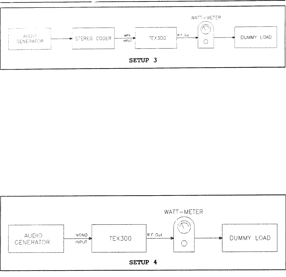
3.6 MONOPHONIC TRANSMISSION
1) Connect the signal source (audio mixer, receiver, compressor etc.) to the MONO input. This
input is unbalanced (see setup 4).
2) Select the desired input level.
3) Adjust the signal level of the equipment connected to the XT300 (with the audio signal
present) for a peak reading of DEV MAX=75KHz
NOTE: International standards permit a maximum deviation (DEV MAX) of 75KHz for frequency
modulated, radiophonic transmissions. Exceeding this limit will only result in the degradation of the
signal quality. In the case of mono transmissions the stereo input is available for frequencies between
15 KHz and 100KHZ (i.e. subcarriers for SCA, RDS etc.).
Pag. 34
Pages 35-68 intentionally left blank
Page intentionally left blank

71
75