BIOTRONIC TECHNOLOGY 52505332333030 WIRELESS BIKE CADENCE SENSOR User Manual
Taiwan Biotronic Technology Inc. WIRELESS BIKE CADENCE SENSOR Users Manual
Users Manual

Lifevisa
W
IRELESS
B
IKE
C
ADENCE
S
ENSOR
[RPS-2300] USER MANUAL
COMPONENTS
1. Cadence Sensor with Screw, Nut & Foam Pad
2. O-Ring
3. 3V CR2032 Lithium Battery
4. Battery Cover
5. Zip Tie for Cadence Sensor X 2pcs
6. Zip Tie for Cadence Magnet X 2pcs
7. Cadence Magnet with Screw & Nut
2.4GHz
CADENCE SENSOR BATTERY INSTALLMENT
This Cadence Sensor includes a 3V CR2032 lithium battery.
Please follow below steps to install the battery.
Step 1.
Insert the battery (CR2032) with the positive (+) side up.
☆
Make sure the battery is hooked by the contact spring.
Step 2.
Put on the O-Ring in the groove to ensure water resistance.
☆
Make sure to place the O-Ring properly in order to prevent battery
composition from being spoiled by rain or water.
Step 3.
Place the battery cover and use a coin to twist it clockwise until it is
tight enough.
NOTE:
☆
Open the battery cover only when changing the battery to ensure a
long life,
and make sure the O-Ring is not damaged, in which case you should
replace
it with a new one.
☆
Keep battery away from children. If swallowed, contact a physician at
Thank you for purchasing Lifevisa products. This manual contains
information required to use Cadence Sensor. Please read this manual
thoroughly before you use the Cadence Sensor.
1 2 3
7
5 & 64
1
2
☆
The effective distance/range is within 10 meters. Be sure no other
devices are within this distance making the same approach.
HOST CONNECTION
This Cadence Sensor must be recognized to the host before being used
for the first time. We recommend making this approach before
installment. Please follow below instructions to complete the
connection.
1. Turn on the host and enter
connection mode. The host will
wait the signal for 1 minute. If
not receiving the signal, the host
will exist the connection mode
automatically.
2. Press the set key of Cadence Sensor. Then wait for connection.
3
3. The host should begin to display a reading, showing the connection has
been done and you can start to install the Cadence Sensor and Magnet.
set key
2.4GHz
Connection
done!!
For the latest version of this user manual and more product information,
please visit our website at
http://www.biotronic.com.tw
NOTE:
☆
This step only has to be done at the first time of use with the same
Cadence Sensor and host. Afterwards, even changing battery, you
don't need to reconnect to the host.
☆
See TROUBLESHOOTING AND CARE section if you are experiencing
connection issues.
The Bike Cadence Sensor measures and sends your pedaling strokes per
minute information to the host. Please follow the simple instructions
below to mount the Cadence on your bike.
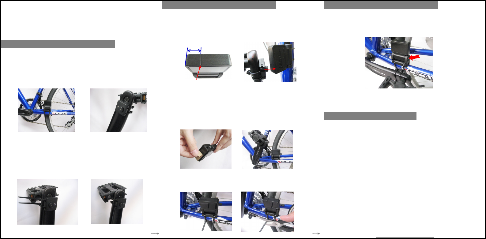
1. Find an appropriate position and place the Cadence Magnet to inner
side
of the crank arm. The Magnet should face toward down tube or
chain stay.
2. Pass 2 zip ties over the Cadence Magnet and tighten them. Carefully
snug 2 zip ties and trim the excess. Make sure the Magnet is mounted
To install Cadence Magnet and Cadence Sensor, you need cutters and
cross-head screwdrivers. Before installment, clean and dry the position of
the device.
4
3. Place the Cadence Sensor on the down tube or chain stay. The
position
of Cadence Sensor should be corresponded to Magnet's. There is an
indication line on the top of the Sensor, which limits the effective
range
that the Magnet could pass through. Align the Magnet to the center of
5. Remove the adhesive of foam pad from Cadence Sensor and attach the
Cadence Sensor to the marked position on the down tube or chain stay.
6. Pass 2 zip ties over the Cadence Sensor and tighten them. Carefully
snug 2 zip ties and trim the excess. Make sure the Cadence Sensor
is mounted securely.
4. Sensor's logo is toward you and you can adjust Sensor's angle to find
the
suitable gap. Remember that the best gap between Cadence Sensor
and
Magnet is about 4mm (0.16"). Pedal to test the alignment of Sensor and
5
TROUBLESHOOTING AND CARE
Troubleshooting of the Cadence Sensor
● If you are not getting a good connection to the host, please
(a) Make sure the position of the Sensor to the Magnet is installed
correctly.
(b) Make sure the gap between the Sensor and Magnet is appropriate.
(c) Check if the battery is installed properly or change a new battery.
(d) Repeat HOST CONNECTION section.
● The effective range of the whole system is 3 meters. If the host is
away
7. Fine-tune the angle of Cadence Sensor to ensure the Magnet can pass
as close to the Sensor as possible but does not touch it. The gap
between the Sensor and the Magnet should be 4mm (0.16"). Finally,
tighten the screw on the Sensor with a screwdriver.
NOTE:
☆
If you have done host connection before installment, make sure you do
not touch the set key accidentally; otherwise, please repeat HOST
CONNECTION section.
Care of the Cadence Sensor and Magnet
● Keep the Cadence Sensor and Magnet clean after every use.
● Keep the Cadence Sensor and Magnet out of extremely cold and hot.
We care about your safety. Make sure the device is not against any parts
of your bike and to avoid being heavily hit during cycling as it may
damage the Sensor.
6
HOW TO INSTALL
THE CADENCE
HOW TO INSTALL
THE CADENCE
HOW TO INSTALL
THE CADENCE
indication
line
effective range
Federal Communication Commission Interference Statement
This equipment has been tested and found to comply with the limits for a Class B
digital device, pursuant to Part 15 of the FCC Rules. These limits are designed to
provide reasonable protection against harmful interference in a residential installation.
This equipment generates, uses and can radiate radio frequency energy and, if not
installed and used in accordance with the instructions, may cause harmful interference
to radio communications. However, there is no guarantee that interference will not
occur in a particular installation. If this equipment does cause harmful interference to
radio or television reception, which can be determined by turning the equipment off
and on, the user is encouraged to try to correct the interference by one of the
following measures:
. Reorient or relocate the receiving antenna.
. Increase the separation between the equipment and receiver.
. Connect the equipment into an outlet on a circuit different from that to which the
receiver is connected.
. Consult the dealer or an experienced radio/TV technician for help.
FCC Caution: To assure continued compliance, any changes or modifications not
expressly approved by the party responsible for compliance could void the user's
authority to operate this equipment. (Example - use only shielded interface cables
when connecting to computer or peripheral devices).
This device complies with Part 15 of the FCC Rules. Operation is subject to the
following two conditions:
(1) This device may not cause harmful interference, and (2) This device must accept
any interference received, including interference that may cause undesired operation.