BIOTRONIK SE and KG BM2 BioMonitor 2-AF, BioMonitor 2-S User Manual QRIBM2 UserMan
BIOTRONIK SE & Co. KG BioMonitor 2-AF, BioMonitor 2-S QRIBM2 UserMan
QRIBM2_UserMan
BioMonitor 2
Implantable cardiac monitor with Home Monitoring
Implantierbarer Herzmonitor mit Home Monitoring
Monitor cardiaco implantable con Home Monitoring
Moniteur cardiaque implantable avec Téléc@rdiologie
Technical manual
Gebrauchsanweisung
Manual técnico
Manuel technique
• en
• de
• es
• fr
( )
BIOTRONIK SE & Co. KG
Woermannkehre 1
12359 Berlin · Germany
Tel +49 (0) 30 68905-0
Fax +49 (0) 30 6852804
sales@biotronik.com
www.biotronik.com
14-D-xx
Revision: (2014-09-05)
© BIOTRONIK SE & Co. KG
All rights reserved. Specifications subject
to modification, revision and improvement.
® BIOTRONIK Home Monitoring and
ProMRI are registered trademarks
of BIOTRONIK SE & Co. KG
0123
0681 2015
1
BioMonitor 2
Implantable cardiac monitor with
Home Monitoring
Technical manual for the device
GA-HW_en_-[[_BioMonitor 2_(ProMRI)
I ndex G A-H W_en-- mul_378622- E_BioMonitor-ProMRI Technical manual for the deviceB ioMonit or
Table of Contents
Table of Contents
Product Description . . . . . . . . . . . . . . . . . . . . . . . . . . . . . . . . . . . . . . . . . . . . . . . . . . . . . . .2
Intended Medical Use . . . . . . . . . . . . . . . . . . . . . . . . . . . . . . . . . . . . . . . . . . . . . . . 2
System Overview . . . . . . . . . . . . . . . . . . . . . . . . . . . . . . . . . . . . . . . . . . . . . . . . . . . 2
Diagnostic Functions. . . . . . . . . . . . . . . . . . . . . . . . . . . . . . . . . . . . . . . . . . . . . . . . 3
General Safety Instructions . . . . . . . . . . . . . . . . . . . . . . . . . . . . . . . . . . . . . . . . . . . . . . . . .4
Operating Conditions . . . . . . . . . . . . . . . . . . . . . . . . . . . . . . . . . . . . . . . . . . . . . . . 4
Possible Complications . . . . . . . . . . . . . . . . . . . . . . . . . . . . . . . . . . . . . . . . . . . . . 4
Possible Risks . . . . . . . . . . . . . . . . . . . . . . . . . . . . . . . . . . . . . . . . . . . . . . . . . . . . . 5
Implantation . . . . . . . . . . . . . . . . . . . . . . . . . . . . . . . . . . . . . . . . . . . . . . . . . . . . . . . . . . . . .6
Implantation Procedure . . . . . . . . . . . . . . . . . . . . . . . . . . . . . . . . . . . . . . . . . . . . . 6
Follow-up. . . . . . . . . . . . . . . . . . . . . . . . . . . . . . . . . . . . . . . . . . . . . . . . . . . . . . . . . 7
Patient Information . . . . . . . . . . . . . . . . . . . . . . . . . . . . . . . . . . . . . . . . . . . . . . . . . 7
Replacement Indications . . . . . . . . . . . . . . . . . . . . . . . . . . . . . . . . . . . . . . . . . . . . 8
Explantation and Device Replacement . . . . . . . . . . . . . . . . . . . . . . . . . . . . . . . . . 8
Parameters . . . . . . . . . . . . . . . . . . . . . . . . . . . . . . . . . . . . . . . . . . . . . . . . . . . . . . . . . . . . . .9
Arrhythmia Detection Parameters. . . . . . . . . . . . . . . . . . . . . . . . . . . . . . . . . . . . . 9
Home Monitoring Parameter Settings. . . . . . . . . . . . . . . . . . . . . . . . . . . . . . . . . 10
Technical Data . . . . . . . . . . . . . . . . . . . . . . . . . . . . . . . . . . . . . . . . . . . . . . . . . . . . . . . . . . .11
Mechanical Characteristics . . . . . . . . . . . . . . . . . . . . . . . . . . . . . . . . . . . . . . . . . 11
Electrical Characteristics. . . . . . . . . . . . . . . . . . . . . . . . . . . . . . . . . . . . . . . . . . . 11
Battery Data. . . . . . . . . . . . . . . . . . . . . . . . . . . . . . . . . . . . . . . . . . . . . . . . . . . . . . 12
Legend for the Label. . . . . . . . . . . . . . . . . . . . . . . . . . . . . . . . . . . . . . . . . . . . . . . 12
2
1 Product Description
Product Descript ion1GA-HW_en- -mul_378622-E_B ioMonit or-Pr oMR ITechn ical manual f or the deviceBioMonitor
Intended Medical Use
Intended use
BioMonitor 2 is the name of an implantable cardiac monitor for the monitoring of heart
rhythm.
Its primary purpose is to provide early detection and diagnostics of symptoms of
arrhythmias, such as atrial fibrillation and the causes of syncope, which can be mani-
fested clinically.
Form of diagnosis
The heart rhythm is continuously monitored; the possible detection types are atrial
fibrillation, high ventricular rate, asystole, or bradycardia. Depending on the preset
parameters, subcutaneous ECGs and other data are recorded.
The patient can also initiate a recording of a subcutaneous ECG.
BIOTRONIK Home Monitoring
®
enables physicians to perform a multi-year diagnosis
management at any time.
Required expertise
In addition to having basic medical knowledge, the user must be thoroughly familiar
with the operation of the implantable cardiac monitor and the specified conditions for
its use. Only qualified medical specialists having the special knowledge are permitted
to implant the BioMonitor 2 and make diagnoses.
Guidelines of cardiological societies
It is recommended that the indications published by the German Cardiac Society
(Deutsche Gesellschaft für Kardiologie, Herz- und Kreislaufforschung) and the ESC
(European Society of Cardiology) are observed. This also applies to the guidelines
published by the Heart Rhythm Society (HRS), the American College of Cardiology
(ACC), the American Heart Association (AHA), and other national cardiology associa-
tions.
Indications
•
Clinical symptoms or increased risk of cardiac arrhythmias
•
Temporary symptoms that may indicate cardiac arrhythmia
Contraindications
There are no known contraindications.
However, the particular patient's state of health determines whether a subcutaneous
device will be tolerated long-term.
System Overview
Device family
BioMonitor 2 is a cardiac monitor.The device family consists of BioMonitor 2-AF and
BioMonitor 2-S. Not all device types are available in ecvery country.
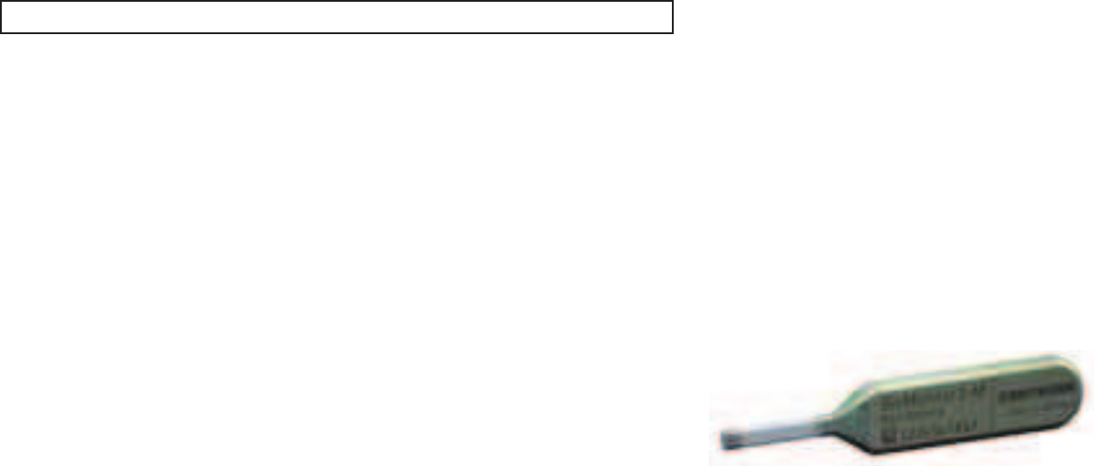
Parts
The system consists of the following parts:
•
Device with electrode integrated in the header and insertion tool
•
Programmer
•
Current software version for the implanted device
•
Remote Assistant for the patient
Cardiac monitor
These devices have a retrospective loop memory, which continuously records the last
minutes of a patient's electrocardiograms. They include a patient-activation function,
which allows the patient to activate ECG storage (with the help of a patient device) as a
result of a symptomatic episode, and an auto-detection function that allows capture of
events without relying on patient compliance or perception of symptoms
The device's housing is made of biocompatible titanium, welded from the outside and
therefore hermetically sealed. It is coated in silicone or parylene. The shape facilitates
ingrowth into the pectoral muscle area.
The cardiac monitor's sensing principle is based on one vector.
The device labeling provides information about the BioMonitor 2.
Note:
BioMonitor 2 does not have a pacing function.

3
Programmer
Implantation and follow-up are performed with a portable BIOTRONIK programmer.
During the implantation, the current device program is transferred to the device on
initial interrogation via the programmer. In addition, the programmer is used to set
parameter combinations, as well as for interrogation and device data storage. Subcuta-
neous ECG, markers, and functions are displayed simultaneously on the color display.
Telemetry
Telemetric communication between the device and the programmer can be carried out
by applying a programming head (PGH).
BIOTRONIK Home Monitoring
®
The BIOTRONIK cardiac monitor provides a complete diagnosis management system:
•
With Home Monitoring, diagnostic information as well as technical data of the
device are automatically and wirelessly sent to a stationary or mobile transmitter
via an antenna in the device header. The data are encrypted and sent from the
transmitter to the BIOTRONIK Service Center via the cellular phone network.
•
The received data are deciphered and evaluated. Each physician can set the criteria
for evaluation to be used for each patient and can configure the time of notification
via E-mail, SMS or fax.
•
A clear overview of the results of this analysis is displayed for the attending physi-
cians on the protected Internet platform Home Monitoring Service Center (HMSC).
•
Data transmission from the device is performed with a daily device message.
•
Device messages which indicate special events in the heart or in the device are
forwarded at the set time.
•
A test message can be initiated at any time using the programmer to immediately
check the Home Monitoring function.
BioMonitor 2 order numbers
Not all device types are available in all countries:
Package contents
The storage package includes the following:
•
Sterile packaging with device
•
Serial number label
•
Patient ID card
•
Technical manual for the device
The sterile packaging includes the following:
•
Device
Note:
It is not permitted to use the device's ECG display for diagnostic purposes
because it does not meet all requirements of the standard (IEC 60601-2-25)
concerning diagnostic ECG devices.
Device Coating Order number
BioMonitor 2-S Silicone 398494
BioMonitor 2-S Parylene 403227
BioMonitor 2-AF Silicone 398493
BioMonitor 2-AF Parylene 403226
4
Diagnostic Functions
General overview
•
Automatic functions simplify the expeditious implantation, configuration, and assess-
ment of the BioMonitor 2.
Detection and data storage
•
Parameters like Sensing high pass filter, Target sensing threshold or Interference
interval are based on the sensing settings and may be customized.
•
The sensing parameters are subsumed in one program (SensingConsult). In addition to
a customized program, there are preconfigured programs for PVC detection, T wave
suppression and Variable amplitude.
•
The signals are recorded and stored once a detection type is set.
•
Multiple detection types can be set simultaneously.
•
Single episodes up to 40 s in length can be stored. Patient-triggered recordings are
stored up to 7.5 min.
•
The device can record a total of 35.8 min of episodes in subcutaneous ECGs.
•
When performing follow-ups using the programmer, the subcutaneous ECG is indi-
cated with markers after applying the programming head.
Home Monitoring functions
Important medical information includes but is not limited to the following:
•
Ongoing atrial and ventricular arrhythmia
•
Current statistics
•
High definition subcutaneous ECGs and sending of these recordings with device
messages
2 General Safety Instructions
General Safety Instruct ions2G A-H W_en--mul_378622- E_BioMonitor 2-P roMRITechnical manual for the dev iceB ioMonit or 2
Operating Conditions
Technical manuals
The following technical manuals provide information about usage of the device systems:
— Technical manual for the device
— Technical manual for the HMSC
— Technical manuals for the programmer and its accessories
— Technical manuals for the user interface
— Technical manuals for cables, adapters and accessories
•
Technical manuals are either included in hard copy form in the product package or in
digital form on the internet:
https://manuals.biotronik.com/manuals/home
•
Follow all relevant technical manuals.
•
Preserve technical manuals for later use.
Care during shipping and storage
•
Devices must not be stored or transported close to magnets or sources of electromag-
netic interference.
•
Observe the 'use by date (UBD)' (see the battery data).
Temperature
Extremely low and high temperatures affect the service time of the battery in the device.
•
The following temperatures are permitted for transport, storage, and use:
-10°C to 45°C
Sterile delivery
The device is delivered after gas sterilization. Sterility is guaranteed only if the blister and
quality control seal have not been damaged.
Sterile packaging
The device is packaged in two separately sealed blisters. The inner blister is also sterile on
the outside so that it can be transferred in a sterile state during implantation.
Single use only
The device is only intended for one-time use.
•
Do not use the device if the package is damaged.
•
The device must not be resterilized and reused.
5
Possible Complications
General information on medical complications
Complications for patients and device systems generally recognized among practitio-
ners also apply to BIOTRONIK devices.
•
Complications may include, for example, foreign body rejection phenomena, local
tissue reactions, migration of the device, or infections. Primary sources of compli-
cation information include current scientific and technological knowledge.
•
It is impossible to guarantee the efficacy of implantable cardiac monitors.
Possible technical failures
Technical failure of a device system cannot be entirely ruled out. Possible causes may
include the following:
•
Device component failures
•
Battery depletion
Electromagnetic interference (EMI)
Any device can be sensitive to interference, for example, when external signals are
sensed as intrinsic rhythm.
•
BIOTRONIK devices have been designed so that their susceptibility to EMI is
minimal.
•
Under unfavorable conditions, especially during diagnostic procedures, sources of
interference may induce such a high level of energy into the device that the data
recording can be influenced or the device may be damaged.
Possible Risks
Procedures to avoid
The following procedures must be avoided as they may cause harm to the patient or
damage the device and, as a result, put the system functionality at risk:
•
Therapeutic ultrasound
•
Transcutaneous electrical nerve stimulation
•
Hyperbaric oxygen therapy
•
Applied higher than normal pressures
Risky therapeutic and diagnostic procedures
If energy from an external source is introduced to the body for diagnostic or therapeutic
purposes, then the device can be subjected to interference and its function can be
impaired.
Harmful effects may occur, for example, during electrocautery, HF ablation, HF
surgery, or lithotripsy. Influences on the device are not always immediately clear.
If risky procedures cannot be avoided, the following should be observed at all times:
•
Electrically insulate the patient.
•
Do not approximate energy nearby the device.
•
Monitor the patient during and after every intervention.
External defibrillation
The device is protected against the energy that is normally induced by external defibril-
lation. Nevertheless, any implanted device may be damaged by external defibrillation.
The sensing properties may change as a result.
•
Place adhesive electrodes anterior-posterior or perpendicular to the axis formed
from the device to the heart at least 10 cm away from the device and from
implanted leads.

6
Radiation therapy
The use of radiation therapy must be avoided due to possible damage to the device and the
resulting impaired functional safety. If this type of therapy is to be used anyway, prior risk/
benefit analysis is absolutely necessary. The complexity of influencing factors such as
different sources of radiation, a variety of devices and therapeutic conditions make it
impossible to issue directives that guarantee radiation therapy without an impact on the
device. The EN 45502 standard pertaining to active implantable medical devices requires
the following information in combination with therapeutic ionizing radiation:
•
Adhere to instructions for potentially risky therapeutic and diagnostic procedures.
•
Shield device against radiation.
•
After applying radiation, double-check the device system to make sure it is functioning
properly.
Magnetic resonance imaging
Magnetic resonance imaging must be avoided due to the associated high frequency fields
and magnetic flux density: damage or destruction of the device by strong magnetic interac-
tion and damage to the patient by excessive warming of the body tissue in the area
surrounding the device.
Under certain conditions and while maintaining mandatory measures, magnetic resonance
imaging can be performed to protect the patient and device.
•
The ProMRI
®
manual – MR conditional device systems – contains detailed information
on safely conducting an MR scan.
—
Download the digital manual from the internet:
https://manuals.biotronik.com/manuals/home
—
Order the printed manual from BIOTRONIK.
•
Does approval as "MR conditional" apply in your country or region? Ask for current
information at BIOTRONIK.
3 Implantation
Implantat ion3G A-H W_en--mul_378622-E_BioMonit or- ProMRI Technical manual for the deviceB ioMon itor
Implantation Procedure
Having parts ready
The following parts that correspond to the requirements of the EC Directive 90/385/EEC
are required:
•
BIOTRONIK device and insertion tool
•
BIOTRONIK programmer and approved cables
•
External multi-channel ECG device
•
Keep spare parts for all sterile components.
Keeping an external defibrillator ready
In order to promptly respond to unforeseeable emergencies or possible technical failures
of the device:
•
Keep an external defibrillator and paddles or patch electrodes ready.
Unpacking the device
•
Peel the sealing paper off of the outer blister at the marked position in the direction
indicated by the arrow. The inner blister must not come into contact with persons who
have not sterilized their hands or gloves, nor with non-sterile instruments!
•
Take hold of the inner blister by the gripping tab and take it out of the outer blister.
•
Peel the sealing paper off of the sterile inner blister at the marked position in the
direction indicated by the arrow.
Implantation site
•
Depending on the patient's anatomy, the BIOTRONIK cardiac monitor can be implanted
subpectorally or subcutaneously on the left side.
Note:
Please contact BIOTRONIK with questions on the risk/benefit analysis.
WARNING
Inadequate function due to defective device
If an unpacked device is dropped on a hard surface during handling, electronic parts
could be damaged.
•
Use a replacement device.
•
Return the damaged device to BIOTRONIK.

7
Preventing leakage currents
Leakage currents between the tools and the device must be prevented during implanta-
tion.
•
Electrically insulate the patient.
Implanting
Position the device optimally
While the device is being positioned, the signals are recorded by the programming
head. It must therefore be placed in the surgical field in sterile condition.
•
Use the programming head with a suitable sterile cover.
Applying the programming head
The programming head features a diagram of the device. This is used to assist in posi-
tioning the head to ensure proper telemetry.
•
Make sure the PGH is positioned correctly.
Establishing telemetry contact
•
When the programming head is applied, time remains for device interrogation. All
detection parameters are disabled during this time.
Activate diagnostics
•
Select the current software version with the standard program on the programmer.
Follow-up
Follow-up intervals
Follow-ups must be performed at regular, agreed intervals.
•
Following the ingrowth phase, approximately 3 months after implantation, the first
follow-up should be carried out by the physician using the programmer (in-office
follow-up).
•
The next in-office follow-up should be carried out once a year and no later than
12 months after the last in-office follow-up.
Follow-up with BIOTRONIK Home Monitoring
®
Monitoring using the Home Monitoring function does not serve to replace regular in-
office appointments with the physician required for other medical reasons. Follow-up
supported by Home Monitoring can be used to functionally replace in-office follow-up
under the following conditions:
•
The patient was informed that the physician must be contacted if symptoms worsen
or if new symptoms arise despite use of the Home Monitoring function.
•
Device messages are transmitted regularly.
•
The physician decides whether the data transmitted via Home Monitoring with
regard to the patient's clinical condition as well as the technical state of the device
system are sufficient. If not, an in-office follow-up has to be carried out.
Possible early detection due to information gained via Home Monitoring may necessi-
tate an additional in-office follow-up. For example, the data may provide early indica-
tion of a foreseeable end of service time (ERI). Furthermore, the data could provide
indications of previously unrecognized arrhythmias.
Follow-up with the programmer
Use the following procedure for in-office follow-up:
1 Form the device pocket with help of the insertion tool.
2 Insert the device.
3 Position the device optimally.
4 Check the signals.
5 Close the device pocket.
CAUTION
Poor signal quality
Unreliable signals may impair sensing and even lead to misinterpreted sensing.
•
Try different positions for the implanted device until the best signals are
displayed on the programmer.
1 Record and evaluate the ECG
2 Interrogate the device.
3 Check the sensing function.
4 Evaluate the status and automatically measured follow-up data.
5 Possibly evaluate statistics and subcutaneous ECGs.
6 If necessary, customize the program functions and parameters.
7 Transmit the program permanently to the device.
8 Print and document follow-up data (print report).
9 Finish the follow-up for this patient.

8
Patient Information
Patient ID card
A patient ID card is included in delivery.
•
Provide the patient with the patient ID.
•
Request that patients contact the physician in case of uncertainties.
Prohibitive signs
Places with prohibitive signs must be avoided.
•
Draw the patient's attention to prohibitive signs.
Possible sources of interference
Electromagnetic interference should be avoided in daily activities. Sources of interfer-
ence should not be brought into close proximity with the device.
•
Draw the patient's attention to special household appliances, safety locks, anti-
theft devices, strong electromagnetic fields, cell phones, and transmitters among
other things.
•
Request patients to do the following:
—
Use cell phones on the opposite side of their body from the device.
—
Keep the cell phone at least 15 cm away from the device both during use and
when storing.
Replacement Indications
Possible battery levels
•
BOS: Beginning of Service: > 70% charge
•
ERI: Elective Replacement Indication
•
EOS: End of Service
Elective Replacement Indication (ERI)
The device can no longer monitor the heart rhythm when in ERI charging status. ERI
can be detected by Home Monitoring.
EOS replacement indication
The end of service has been reached.
Explantation and Device Replacement
Explantation
•
Interrogate the device status.
•
Remove the device using state-of-the-art technology.
•
Explants are biologically contaminated and must be disposed of safely due to risk of
infection.
Device replacement
Basic principles:
•
The device must not be resterilized and reused.
Cremation
Devices should not be cremated.
•
Explant the device before the cremation of a deceased patient.
Disposal
BIOTRONIK takes back used products for the purpose of environmentally safe disposal.
•
Clean the explant with a solution of at least 1% sodium hypochlorite.
•
Rinse off with water.
•
Send the cleaned explant to BIOTRONIK.

9
4 Parameters
P arameters4GA- HW_en--mul_378622-E_B ioMonit or-Pr oMR ITechnical manual f or the deviceBioMonitor
Note: All parameters are subject to change!
Arrhythmia Detection Parameters
SensingConsult
The programs with sensing expert parameters (SensingConsult) are preset as follows:
Sensing settings
The sensing expert parameters included in the programs can be customized as follows:
Diagnostics: Atrial fibrillation
The following can be set:
The programs with AF expert parameters are preset as follows:
The AF expert parameters included in the programs can be customized as follows:
Parameter Programs
Standard T-wave
suppression Variable
amplitude PVC detec-
tion
Lower sensing
threshold
50% 40% 35% 25%
Sensing high pass filter 10 Hz 18 Hz 10 Hz 10 Hz
Recordings and real-
time ECG
Full
morphology
Full
morphology
Full
morphology
Full
morphology
Interference interval 100 ms 100 ms 100 ms 100 ms
Parameter Range of values Standard Factory
Sensing settings (Sens-
ingConsult)
Standard;
T-wave suppression;
Variable amplitude;
PVC detection
Standard Standard
Lower sensing threshold 25; 35; 40; 50% 50% 50%
Sensing high pass filter OFF
10; 18; 24 Hz
10 Hz 10 Hz
Recordings and real-time
ECG
Sensing signal; full
morphology
Full
morphology
Full
morpholog
y
Interference interval 100; 140; 180 ms 100 ms 100 ms
Parameter Range of values Standard Factory
Atrial fibrillation (AF) ON; OFF ON OFF
AF sensitivity Low Medium High
RR variability limit 18.75% 12.5% 6.25%
Analysis window
Onset/end
16/24 8/16 8/16
Onset intervals 9 5 5
Resolution intervals 3 1 1
Confirmation time 6 min 6 min 6 min
Parameter Range of values Standard Factory
RR variability limit 6.25; 12.5; 18.75% 12.5% —
Analysis window
onset/end
8/16; 16/24; 24/32
detection/end
8/16 —
Onset intervals 5 ... (2) ... 23 minimum number
of consecutive RR cycles with an
RR interval outside of the vari-
ability limit
5 —
Resolution intervals 1 ... (2) ... 7 maximum number of
consecutive RR cycles with an
RR interval outside of the vari-
ability limit
3 —
Confirmation time 1 ... (1) ... 6; 10; 20; 30 min 6 min —

10
Diagnostics: High ventricular rate
The following can be set:
Diagnostics: Bradycardia
The following can be set:
Additional bradycardia expert parameters can be set:
Diagnostics: Asystole duration
The following can be set:
Diagnostics: Patient trigger
The following can be set:
Global parameters
The following settings apply to all detection types:
Home Monitoring Parameter Settings
Home Monitoring: HM episode trigger
Home Monitoring can be set for all detection types:
Global parameters
The following settings apply to all detection types:
Parameter Range of values Standard Factory
High ventricular rate ON; OFF ON OFF
HVR limit 150 ... (10) ... 200 bpm 180 bpm —
HVR counter 4; 8; 12; 16; 32; 64 16 —
Parameter Range of values Standard Factory
Brady zone limit OFF
30 ... (5) ... 80 bpm
40 bpm OFF
Brady duration 5 ... (5) ... 30 s 10 s —
Brady rate decrease OFF
10 ... (10) ... 50%
50% —
Brady sensitivity Low; medium; high Low —
Parameter Range of values Standard Factory
Baseline intervals 32; 48; 64 64 —
Rate-drop intervals 4; 8; 16 16 —
Parameter Range of values Standard Factory
Asystole duration OFF
2 ... (1) ... 10 s
3 s OFF
Parameter Range of values Standard Factory
Patient trigger ON; OFF ON OFF
Parameter Range of values Standard Factory
Start resting period 00:00 ... (60) ... 23:00 hh:mm 2:00 hh:mm —
Duration of resting period 00:30 ... (30) ... 12:00 hh:mm 4:00 hh:mm —
Parameter Range of values Standard Factory
Home Monitoring ON; OFF ON OFF
HM episode trigger: AF; HVF;
Bradycardia; Asystole; Patient
trigger
ON; OFF ON OFF
Note:
Depending on the set detection type, the oldest, newest, and the longest
episode is stored. In the case of patient-triggered recordings, the oldest and the two
newest episodes are stored.
Parameter Range of values Standard Factory
Time of transmission STD; 00:00 ... (30) ...
23:30 hh:mm
STD —
Periodic subcutaneous ECG OFF; 1; 2; 30; 60; 90;
120; 180 days
30 days —

11
5 Technical Data
Technical Dat a5G A-HW_en-- mul_378622-E_B ioMonit or- ProMR ITechnical manual f or the dev iceBioMonitor
Mechanical Characteristics
Measurements for the housing
X-ray identification
BIO VP
Materials in contact with body tissue
•
Housing: titanium
•
Leads: titanium, fractally coated
•
Housing sheath: silicone
•
Silicone plug (screw cover): Silicone
•
Header: epoxy resin
Electrical Characteristics
Components and input values
Electrical characteristics determined at 37°C, 500 Ω:
Telemetry
Telemetry data for Home Monitoring:
Telemetry data
•
Nominal carrier frequency: 403.62 MHz
•
Maximum power of transmission: < 25 µW (–16 dBm)
International radio certification
Devices with BIOTRONIK Home Monitoring
®
are equipped with an antenna for wireless
communication.
•
Telemetry information for Canada:
This device must neither interfere with meteorological and earth resources
technology satellites nor with meteorological stations working in the 400,150 to
406,000 MHZ band, and it must accept any interference received, including inter-
ference that may cause undesired operation.
This device will be registered with Industry Canada under the following number:
IC: 4708A-BM2
The code IC in front of the certification/registration number only indicates that the
technical requirements for Industry Canada are met.
•
Telemetry information for Japan:
Japanese Radio Law and Japanese Telecommunications Business Law Compli-
ance.
This device is granted pursuant to the Japanese Radio Law
and the Japanese Telecommunications Business Law
This device should not be modified (otherwise the granted designation number will
become invalid
R: 202-SMC062
•
Telemetry information for the USA:
Telemetry data for the USA: This transmitter is authorized by rule under the
Medical Device Radiocommunication Service (in part 95 of the FCC Rules) and must
not cause harmful interference to stations operating in the 400.150-406.000 MHz
band in the Meteorological Aids ( i.e., transmitters and receivers used to communi-
cate weather data), the Meteorological Satellite, or the Earth Exploration Satellite
Services and must accept interference that may be caused by such stations,
including interference that may cause undesired operation. Analog and digital
voice communications are prohibited. Although this transmitter has been approved
by the Federal Communications Commission, there is no guarantee that it will not
receive interference or that any particular transmission from this transmitter will
be free from interference.
This device will be registered with Federal Communications Commission under the
following number:
FCC ID: QRIBM2
Device W x H x D [mm] Volume [cm
3
]Mass [g]
BioMonitor 2 85 x 15 x 6,5 4.5 10 g [± 2 g]
Circuit Hybrid electronics with VLSI-CMOS chip
Input impedance > 50 kΩ
Nominal carrier frequency Maximum power of transmission
403.62 MHz < 25 µW
-16 dBm
(電気通信事業法)
(電波法)
12
Battery Data
Note: All battery data are subject to change!
Battery characteristics
The following data is provided by the manufacturers:
Power consumption
•
Battery current: 9 µA
•
Average additional battery current in transmission mode: 4 µA
Average service time
Average service times are precalculated using the battery manufacturer's technical
specifications and the setting of different detection parameters.
For BioMonitor 2: 4 years
Shortening of the service time after long storage period
Depending on the storage period, the service time from the beginning of service BOS to
the replacement time ERI decreases as follows:
•
After 1 year: by n.N. months
•
After 1.5 years: by n.N. months
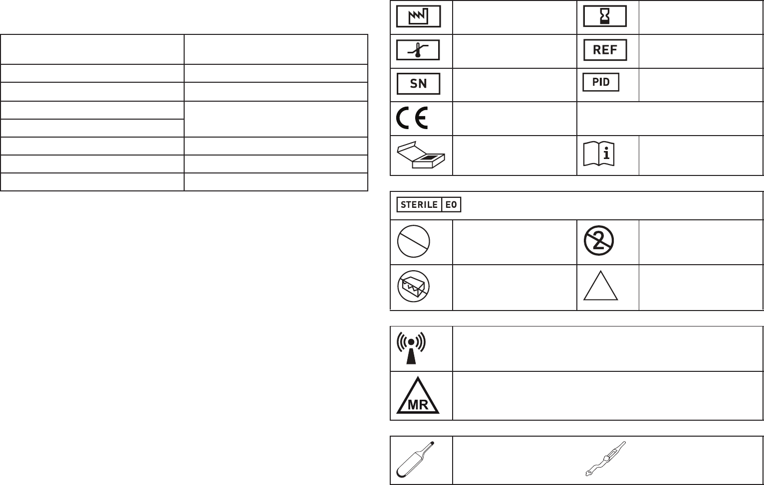
Legend for the Label
The label icons symbolize the following:
Manufacturer LITRONIK GmbH 01796 Pirna
Germany
Battery type LiS 2460
System LiMn0
x
Type of device
Battery voltage at BOS 3.1 V
Open-circuit voltage 3.1 V
Nominal capacity 1.2 Ah
Remaining capacity at ERI 0.15 Ah
Manufacturing date Use by
Storage temperature Order number
Serial number Product identification
number
CE mark
Contents Follow the instructions for
use
Sterilized with ethylene oxide
Do not resterilize Single use only. Do not
reuse!
Do not use if packaging is
damaged
Non-sterile
Transmitter with non-ionizing radiation at designated frequency
MR conditional: Patients can be examined using an MRI scan under
defined conditions if the device system in their body consists of devices
whose packaging is labeled with this symbol.
Implantable cardiac
monitor
I
Insertion tool
STERILIZE
2
NON
STERILE