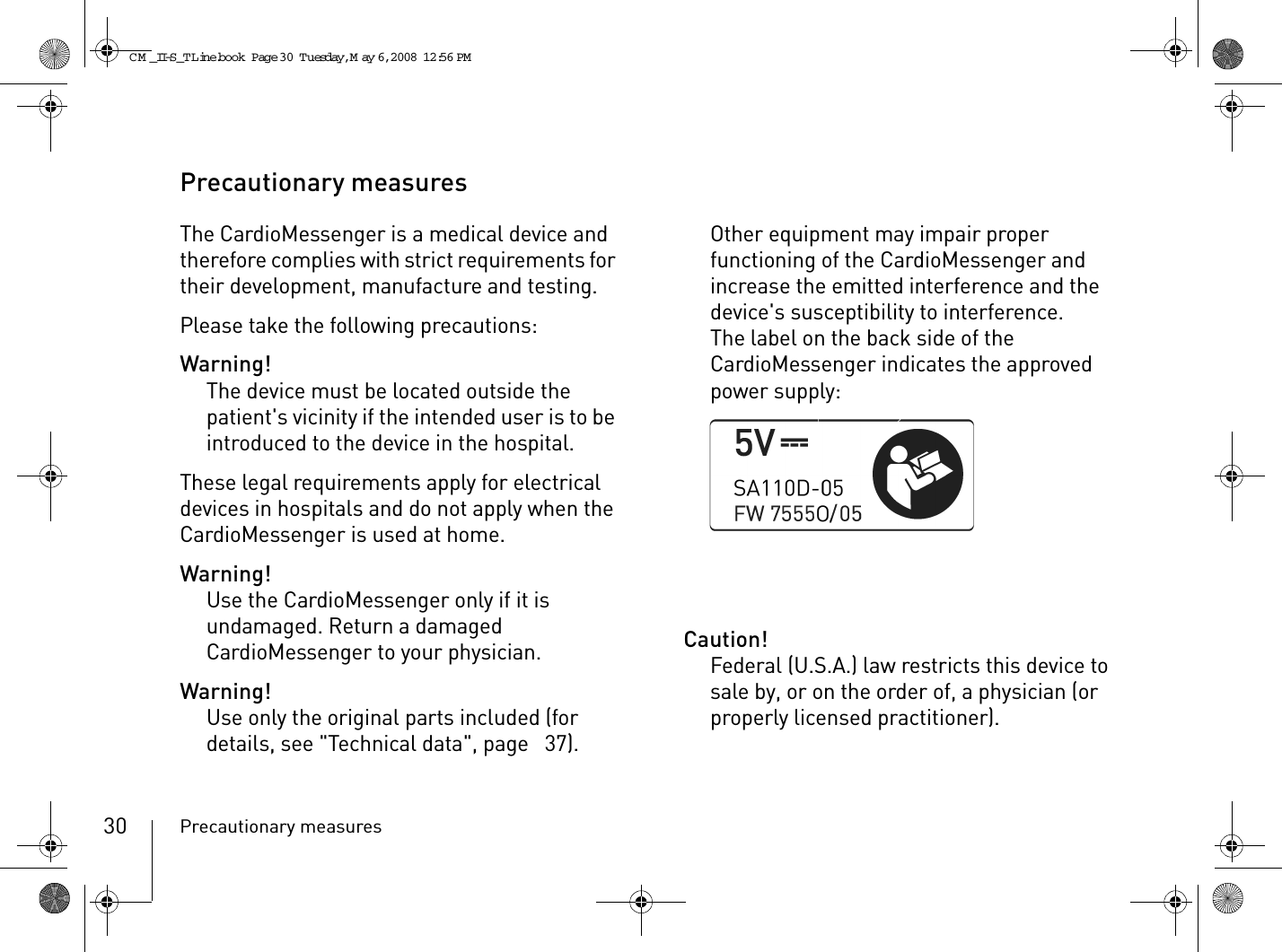
BIOTRONIK SE and KG CM08V-1 Patient Device User Manual 362453 D GA CM II S TLine US indd
BIOTRONIK SE & Co. KG Patient Device 362453 D GA CM II S TLine US indd
UserManual.wiki
>
BIOTRONIK SE and KG
>
CM08V-1 User Manual
>
Manual1
Contents
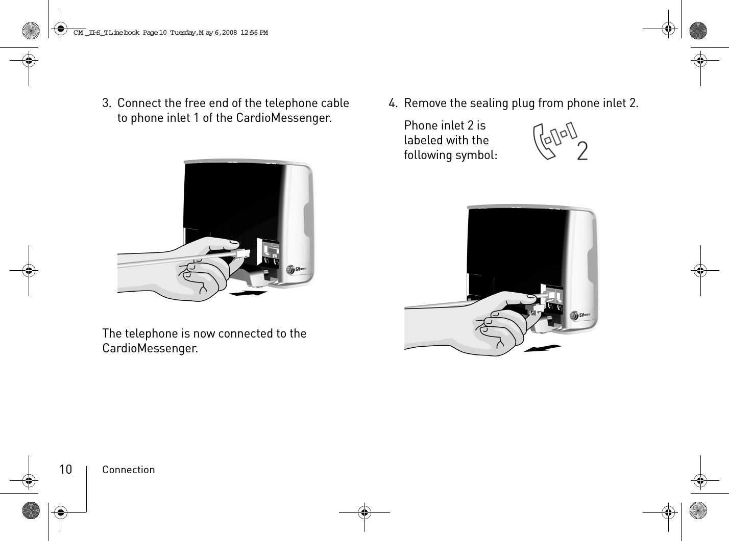
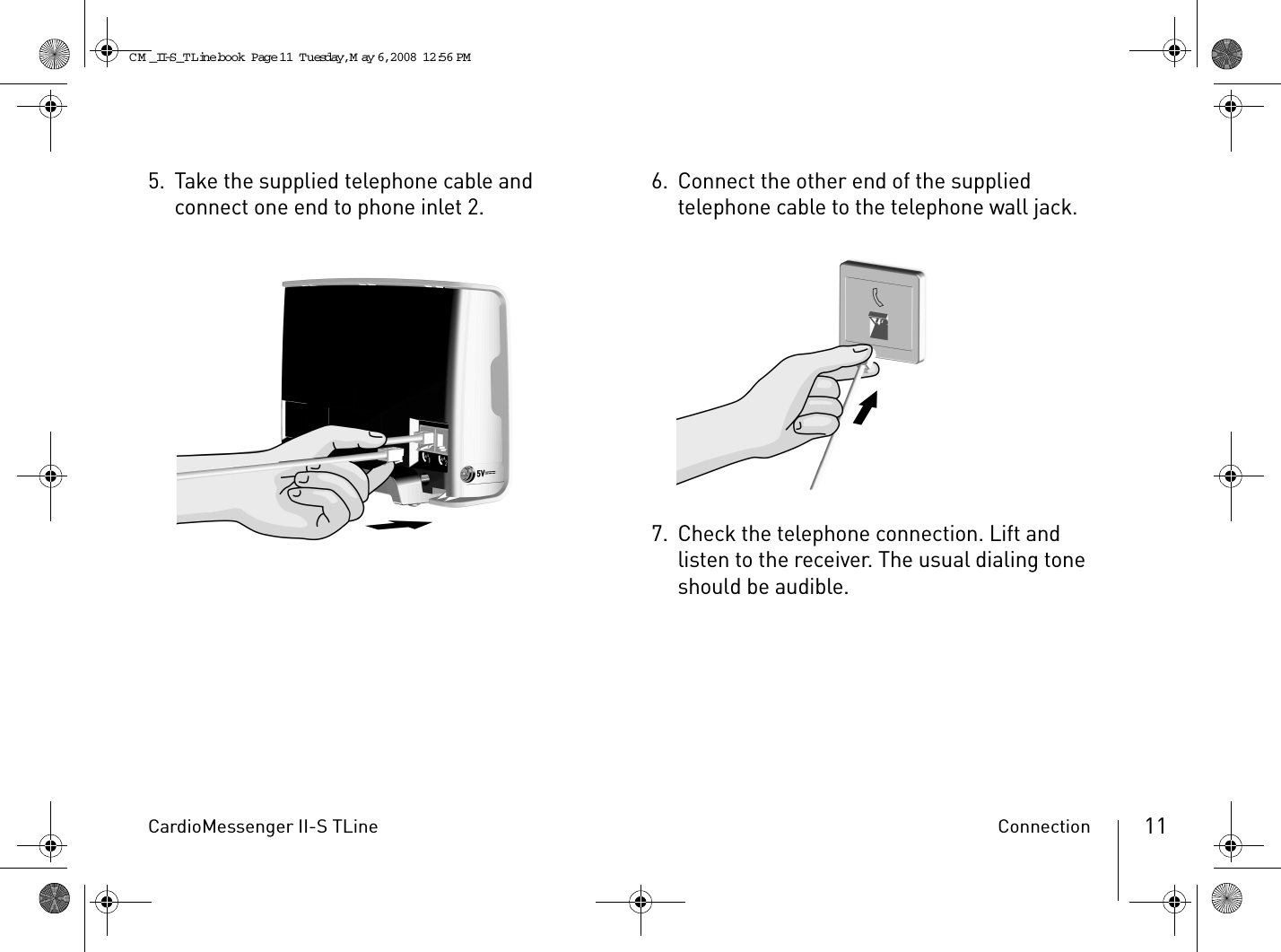
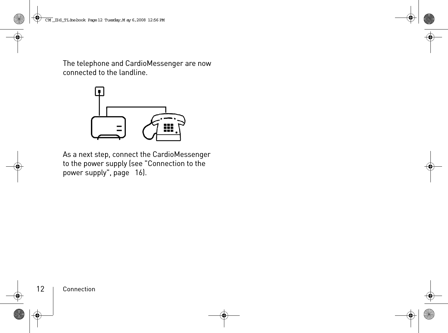
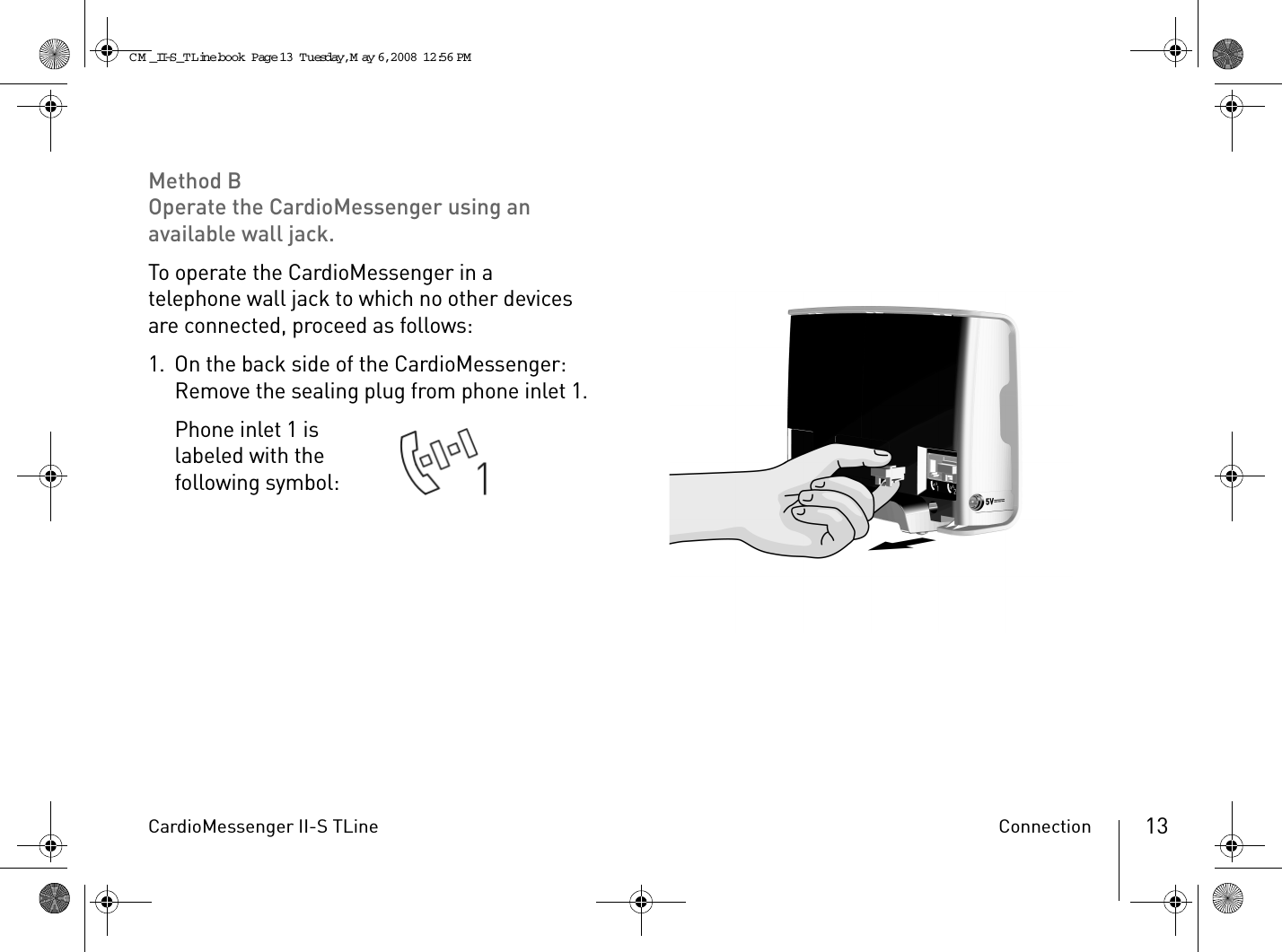
1.
Manual1
2.
Manual2
Manual1
Navigation menu
Upload a User Manual
Namespaces
Wiki Guide
HTML
PDF
Info
Views
User Manual
Discussion / Help
Navigation