BIOTRONIK SE and KG CM08V-1 Patient Device User Manual 362453 D GA CM II S TLine US indd
BIOTRONIK SE & Co. KG Patient Device 362453 D GA CM II S TLine US indd
Contents
- 1. Manual1
- 2. Manual2
Manual1
CardioMessenger®II-S TLine
Transmitter for BIOTRONIK Home Monitoring®
Technical Manual
362453_D_GA_CM_II-S_TLine_US.ind1 1 17.04.08 16:29:59
©
®
by BIOTRONIK GmbH & Co. KG
All rights reserved. Specifications subject to
modification, revision and improvement.
2008-D-05
CardioMessenger is a registered trademark of
BIOTRONIK GmbH & Co. KG
BIOTRONIK mbH & o K
Woermannkehre 1
12359 Berln ermany
Tel +49 (0) 30 68905-0
Fax +49 (0) 30 6852804
BIOTRONIK, Inc
6024 SW Jean rd Bldg B
Lake Oswego, OR 97035
Phone (800) 547-0394 (24-hr)
Fax (503) 635-9936
salesbotronkcom
wwwbotronkcom
362453_D_GA_CM_II-S_TLine_US.ind2 2 17.04.08 16:30:00
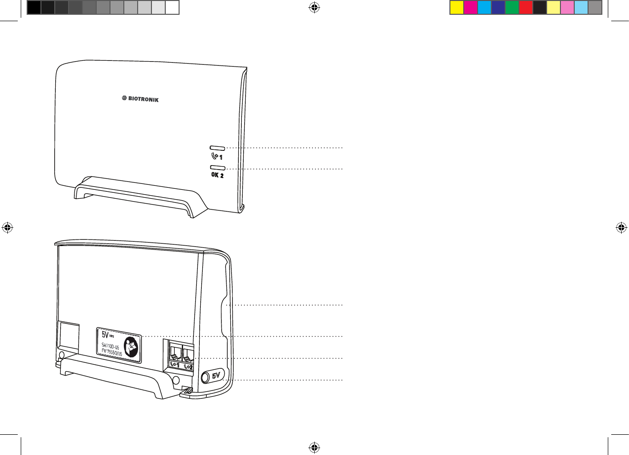
Call back light (yellow, page 22)
Operating light (yellow/green, page 21)
Use only original power supply units (page 16)
Slot for the brief instructions guide (page 20)
Connection for the power supply (page 16)
Connections for the landline (page 9 - 14)
362453_D_GA_CM_II-S_TLine_innen_1 1 05.05.08 15:00:47

CardioMessenger II-S TLine 1
Content
Introduction . . . . . . . . . . . . . . . . . . . . . . . . . . 3
How Home Monitoring works. . . . . . . . . . . 3
Check the completeness of the delivery . . . 5
Setup . . . . . . . . . . . . . . . . . . . . . . . . . . . . . . . 7
Connection . . . . . . . . . . . . . . . . . . . . . . . . . . . 8
Connection to the landline . . . . . . . . . . . . . 8
Connection to the power supply. . . . . . . . 16
Self-test . . . . . . . . . . . . . . . . . . . . . . . . . . . 18
Insert brief instructions guide . . . . . . . . . 20
Operate . . . . . . . . . . . . . . . . . . . . . . . . . . . . 21
Check lights . . . . . . . . . . . . . . . . . . . . . . . 21
Call back function . . . . . . . . . . . . . . . . . . . 22
Switching Off the System. . . . . . . . . . . . . 23
Debugging . . . . . . . . . . . . . . . . . . . . . . . . . . 24
Cleaning, maintenance, and disposal . . . . 28
Precautionary measures . . . . . . . . . . . . . . 30
Guidelines . . . . . . . . . . . . . . . . . . . . . . . . . . 33
Technical data . . . . . . . . . . . . . . . . . . . . . . . 37
Appendix . . . . . . . . . . . . . . . . . . . . . . . . . . . 39
Index . . . . . . . . . . . . . . . . . . . . . . . . . . . . . . 45
362453--D
CM _II-S_TLine.book Page 1 Tuesday, May 6, 2008 12:56 PM

2
CM _II-S_TLine.book Page 2 Tuesday, May 6, 2008 12:56 PM
CardioMessenger II-S TLine Introduction 3
Introduction
Dear patient:
You have received a pacemaker or implantable
cardioverter-defibrillator (ICD) with the
additional Home Monitoring function by
BIOTRONIK.With Home Monitoring, the state of
your heart's health and your implant are
surveyed on a daily basis while you are at
home. Your physician can catch up at regular
intervals on how your heart is doing.
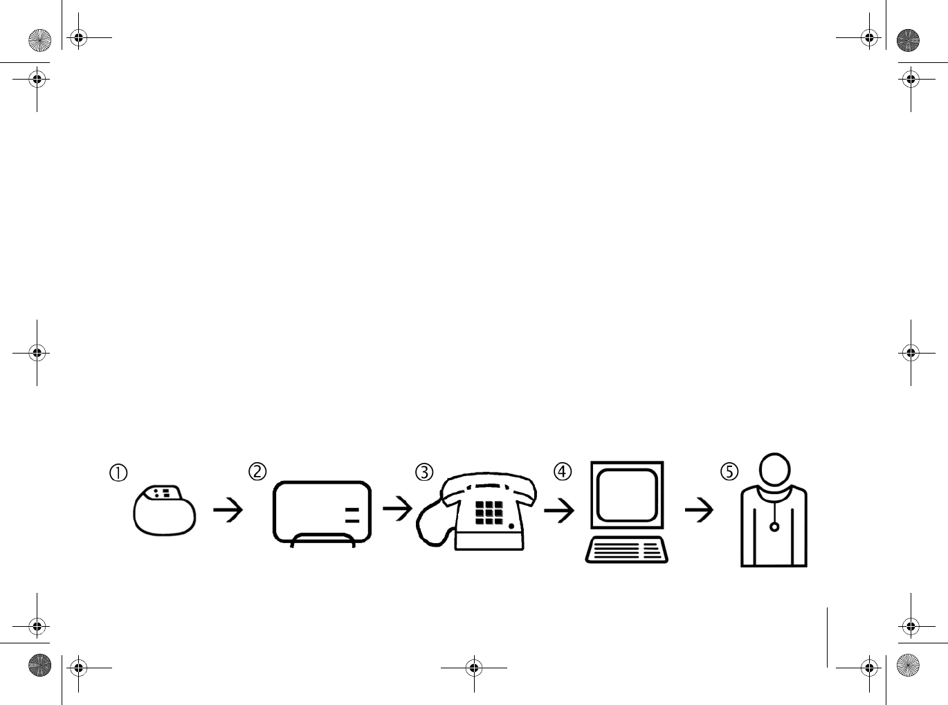
How Home Monitoring works
Your implant is equipped with a special
transmitter (1). Usually at night, the
transmitter sends daily information on your
heart to the patient device, your
CardioMessenger (2).
The transmission power from your implant is
low and does not impair your health in any way.
Its limited transmission range, however,
requires the use of the CardioMessenger.
The CardioMessenger collects the information
received from the implant and automatically
transmits it to the
CM _II-S_TLine.book Page 3 Tuesday, May 6, 2008 12:56 PM

Introduction
4
BIOTRONIK Service Center (4) as encoded
messages via a landline connection (3).
Here, the messages are decoded and made
available for viewing by your physician (5) on a
protected web site.
Based on the information received, your
physician can decide if your implant is best
configured, or if the therapy needs
adjustments. In this way, Home Monitoring
serves as a practical diagnostic aid to your
physician.
CM _II-S_TLine.book Page 4 Tuesday, May 6, 2008 12:56 PM
CardioMessenger II-S TLine Check the completeness of the delivery 5
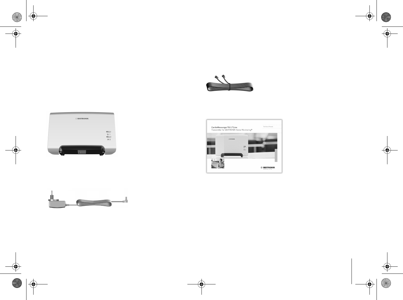
Check the completeness of the delivery
Check all components for visible damage
before using them. Use only components
which are undamaged.
The delivery includes the following:
CardioMessenger II-S TLine
Power supply unit with electricity cable and DC
plug
Telephone cable
Technical manual with brief instructions guide
Warning!
Use the CardioMessenger only if it is
undamaged. Return a damaged
CardioMessenger to your physician.
CM _II-S_TLine.book Page 5 Tuesday, May 6, 2008 12:56 PM
Check the completeness of the delivery
6
Warning!
Use only the original parts included (for
details, see "Technical data", page 37).
Other equipment may impair proper
functioning of the CardioMessenger and
increase the emitted interference and the
device's susceptibility to interference.
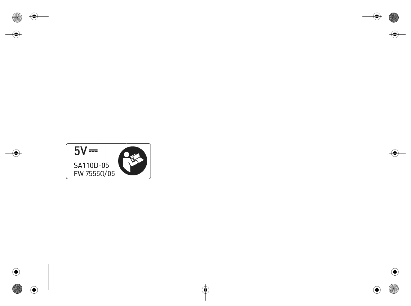
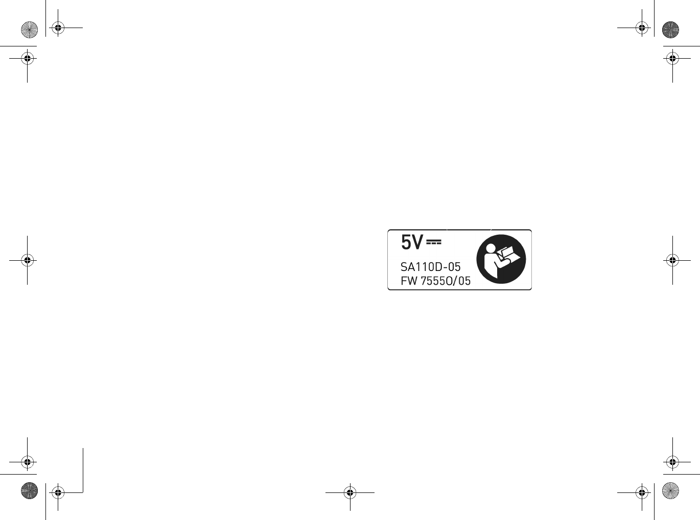
The label on the back side of the
CardioMessenger indicates the approved
power supply:
CM _II-S_TLine.book Page 6 Tuesday, May 6, 2008 12:56 PM
CardioMessenger II-S TLine Setup 7
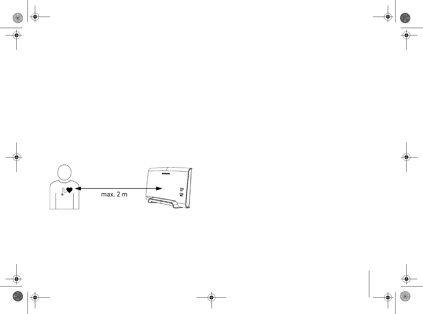
Setup
Place the CardioMessenger on your bedside
table. The bedside table is suitable because it
usually meets the following conditions:
2
The CardioMessenger is placed on a solid
base and cannot fall.
2
The distance to the implant is less than 2
meters so that regular data transmission at
night is assured.
Please take the following into consideration:
2
Place the CardioMessenger in such a way
that the lights can easily be viewed during
the day. If the lights disturb you in your
sleep, turn the CardioMessenger away from
you. Do not place the CardioMessenger on
the floor, next to, or under your bed.
2
Do not place the CardioMessenger next to a
television set, microwave oven, or a similar
source of electromagnetic interference.
2
Do not expose the CardioMessenger to
temperatures exceeding 40 °C (104 °F). Do
not put it on a place with direct sun light and
do not place it directly under a halogen
spotlight.
2
Do not expose the CardioMessenger to
temperatures lower than 10°C (50°F).
2
Protect the CardioMessenger against water
and high humidity. Do not place it in the
bathroom.
CM _II-S_TLine.book Page 7 Tuesday, May 6, 2008 12:56 PM
Connection
8
Connection
Connection to the landline
The CardioMessenger transmits the Home
Monitoring data via landline.
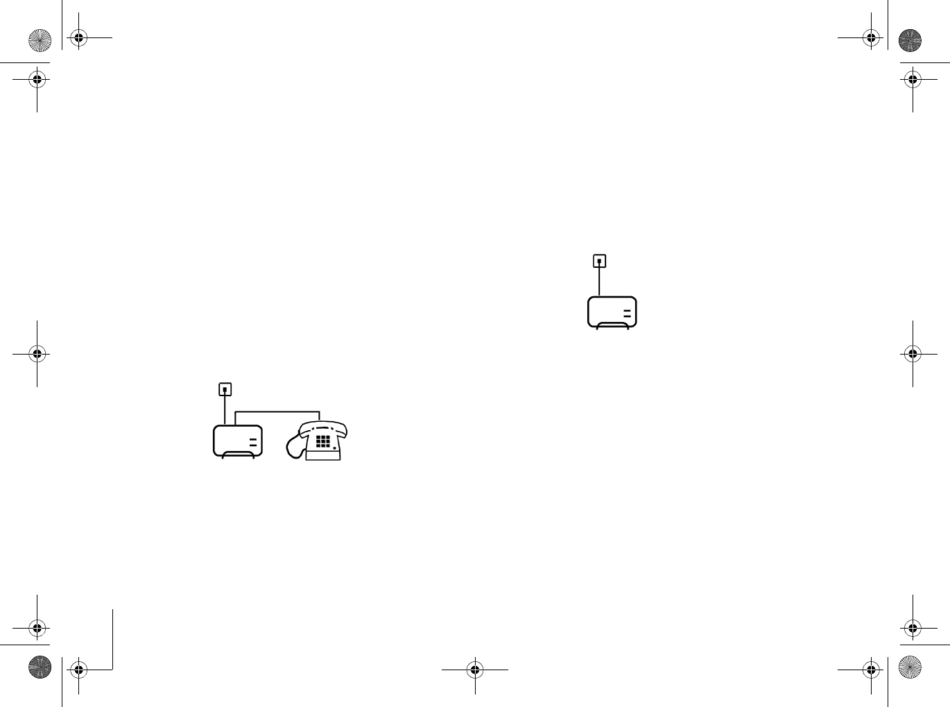
There are two ways to connect the
CardioMessenger to the landline:
2
Method A
CardioMessenger and telephone are
operated using the same telephone wall
jack.
2
Method B
The CardioMessenger is operated with a
telephone wall jack to which no other device
is connected.
In both cases, you can use your phone as
usual.
Note
The CardioMessenger has been designed
for use with an analog landline. Correct
operation cannot be ensured if using a
digital landline. If you are unsure what kind
of landline you are using, please contact
your telephone provider.
CM _II-S_TLine.book Page 8 Tuesday, May 6, 2008 12:56 PM
CardioMessenger II-S TLine Connection 9
Method A
To operate both the CardioMessenger and
the telephone using one telephone jack
To operate CardioMessenger and telephone
together in one telephone wall jack, proceed as
follows:
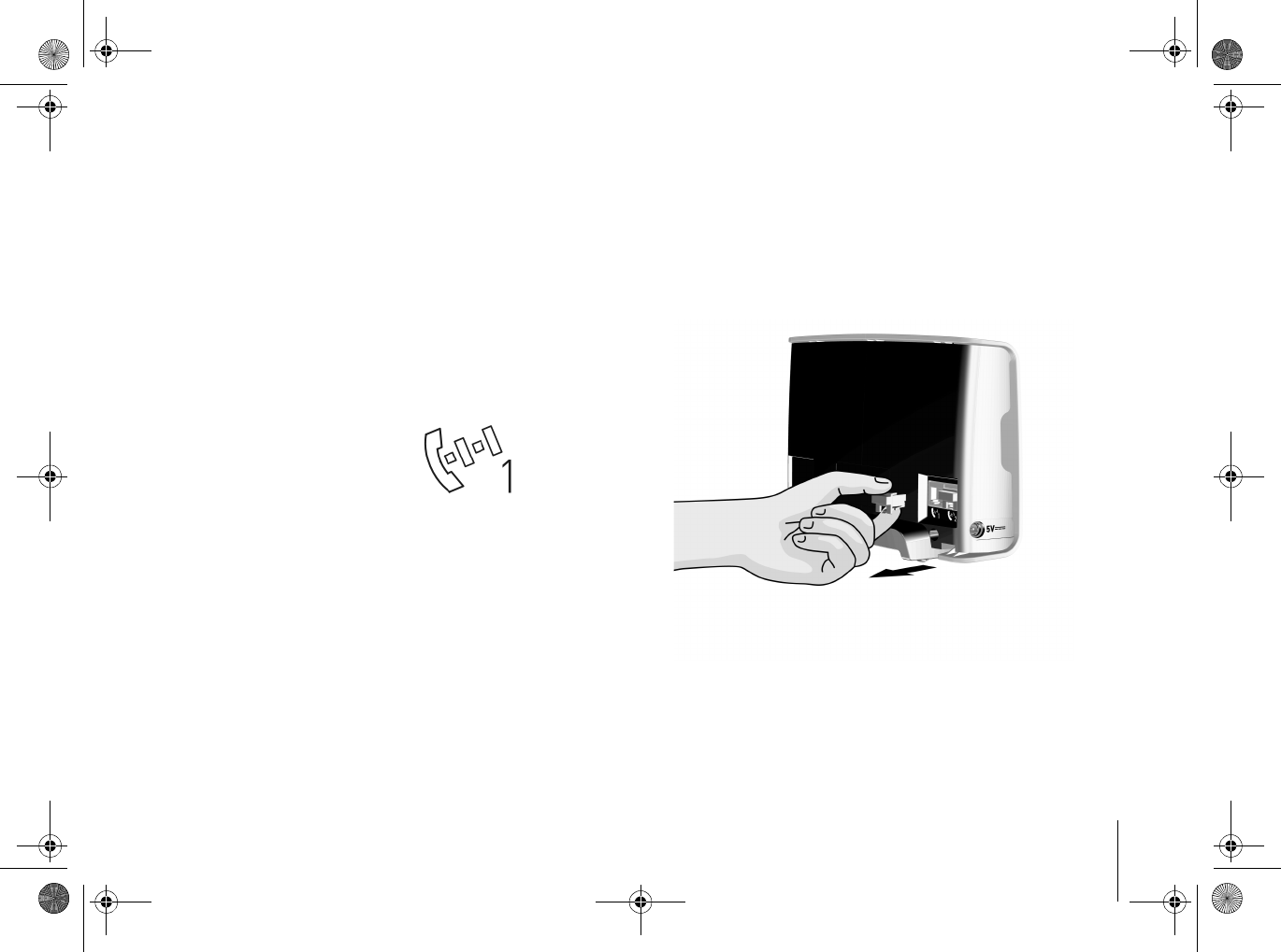
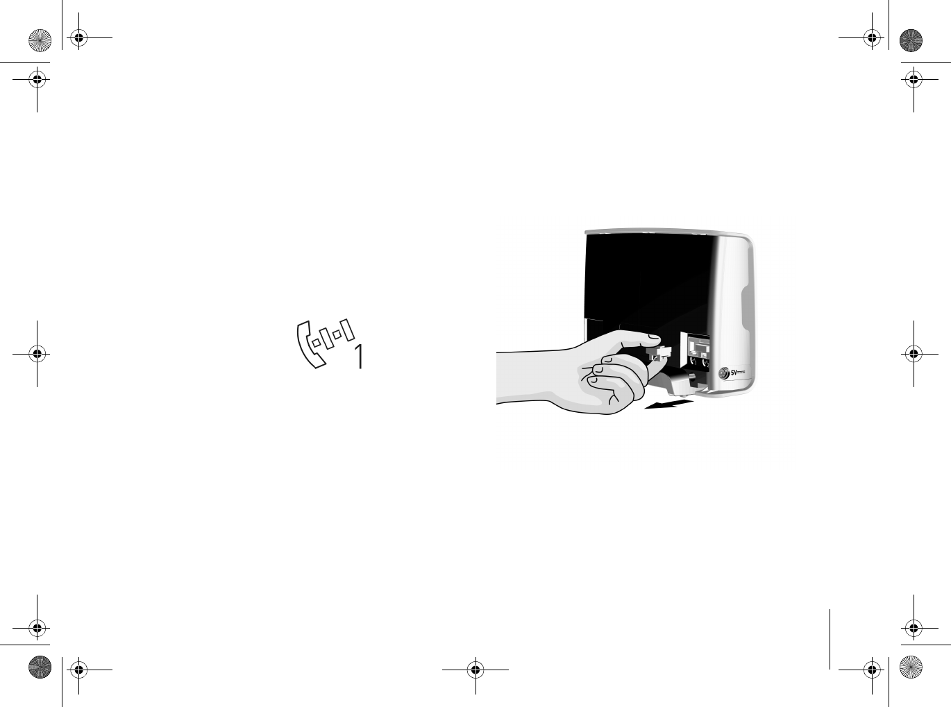
1. On the back side of the CardioMessenger:
Remove the sealing plug from phone inlet 1.
Phone inlet 1 is labeled
with the following
symbol:
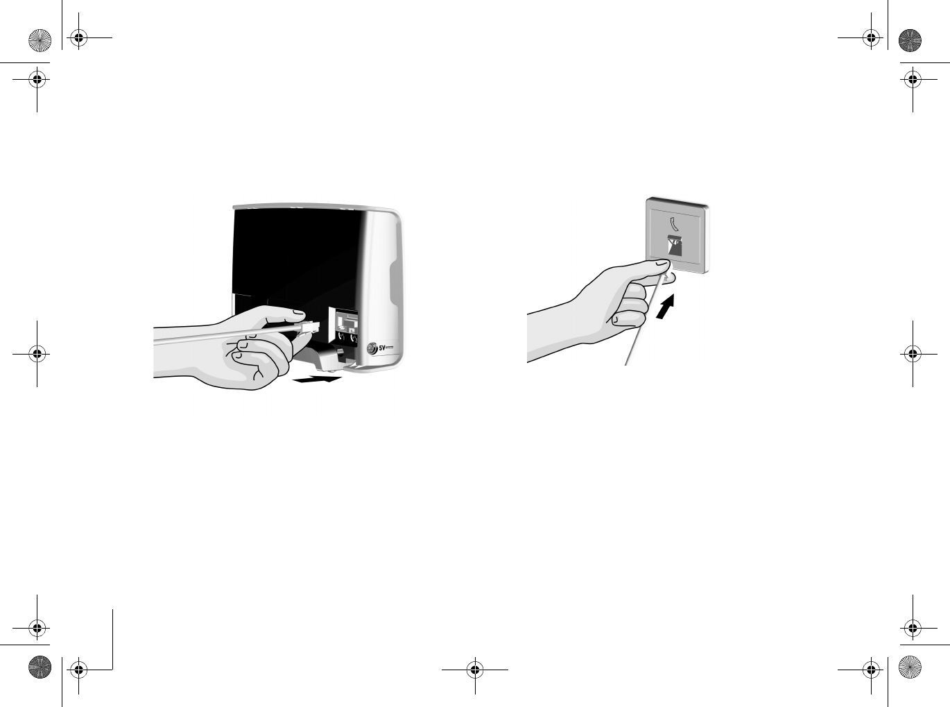
2. Unplug the telephone cable from the
telephone wall jack.
CM _II-S_TLine.book Page 9 Tuesday, May 6, 2008 12:56 PM
Connection
10
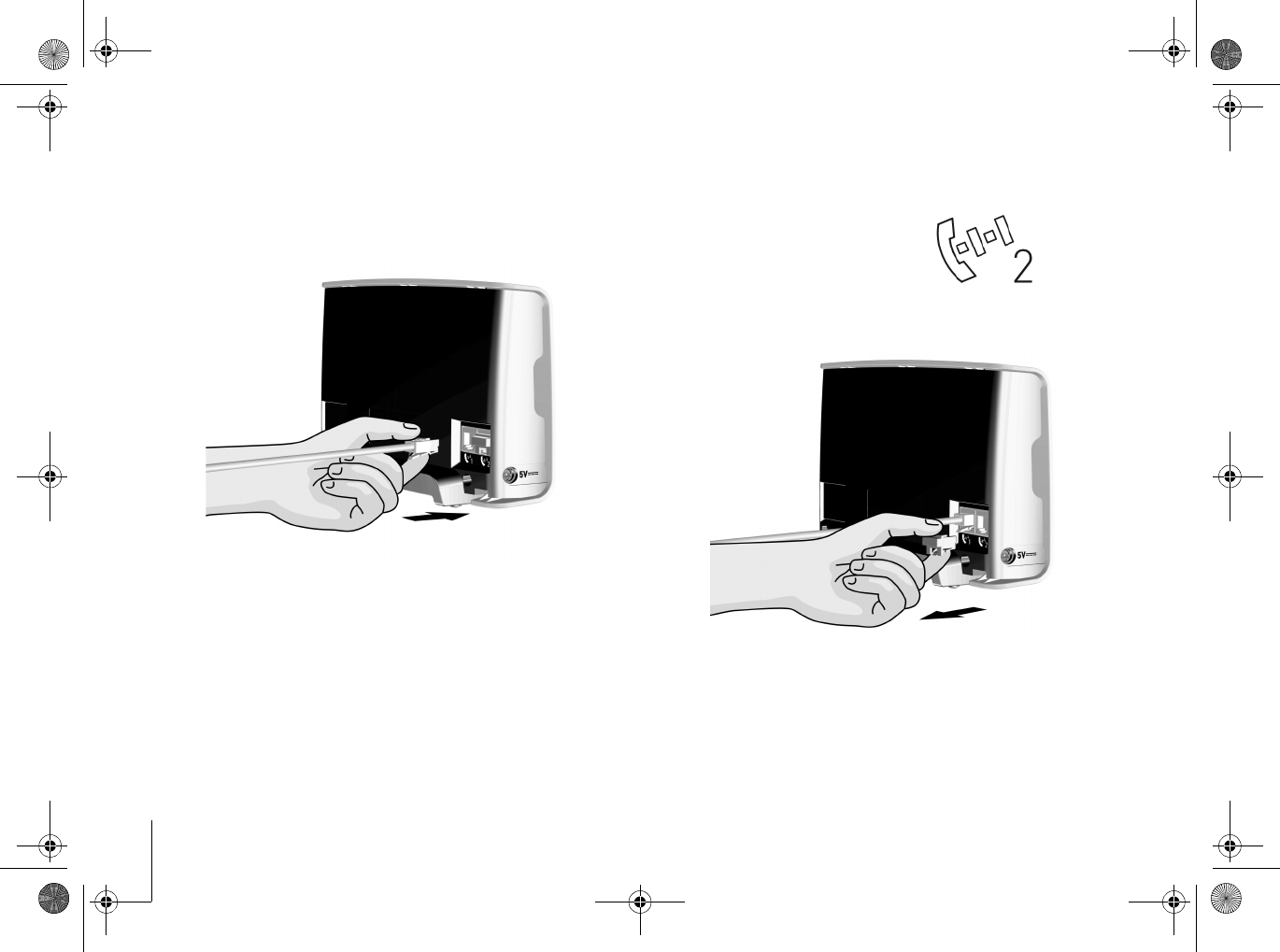
3. Connect the free end of the telephone cable
to phone inlet 1 of the CardioMessenger.
The telephone is now connected to the
CardioMessenger.
4. Remove the sealing plug from phone inlet 2.
Phone inlet 2 is
labeled with the
following symbol:
CM _II-S_TLine.book Page 10 Tuesday, May 6, 2008 12:56 PM
CardioMessenger II-S TLine Connection 11
5. Take the supplied telephone cable and
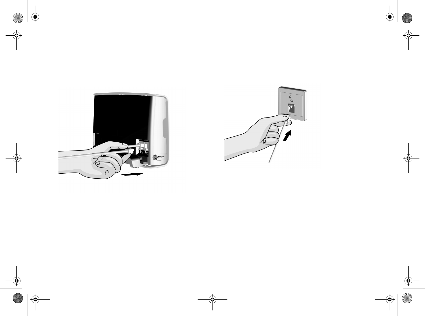
connect one end to phone inlet 2. 6. Connect the other end of the supplied
telephone cable to the telephone wall jack.
7. Check the telephone connection. Lift and
listen to the receiver. The usual dialing tone
should be audible.
CM _II-S_TLine.book Page 11 Tuesday, May 6, 2008 12:56 PM
Connection
12
The telephone and CardioMessenger are now
connected to the landline.
As a next step, connect the CardioMessenger
to the power supply (see "Connection to the
power supply", page 16).
CM _II-S_TLine.book Page 12 Tuesday, May 6, 2008 12:56 PM
CardioMessenger II-S TLine Connection 13
Method B
Operate the CardioMessenger using an
available wall jack.
To operate the CardioMessenger in a
telephone wall jack to which no other devices
are connected, proceed as follows:
1. On the back side of the CardioMessenger:
Remove the sealing plug from phone inlet 1.
Phone inlet 1 is
labeled with the
following symbol:
CM _II-S_TLine.book Page 13 Tuesday, May 6, 2008 12:56 PM
Connection
14
2. Take the supplied telephone cable and
connect one end to phone inlet 1. 3. Connect the other end of the supplied
telephone cable to the telephone wall jack.
CM _II-S_TLine.book Page 14 Tuesday, May 6, 2008 12:56 PM
CardioMessenger II-S TLine Connection 15
The CardioMessenger is now connected to the
landline.
As a next step, connect the CardioMessenger
to the power supply (see "Connection to the
power supply", page 16).
CM _II-S_TLine.book Page 15 Tuesday, May 6, 2008 12:56 PM
Connection
16
Connection to the power supply
Connect the CardioMessenger to the power
supply. The outlet to be used has to be easily
accessible. Use the supplied power supply unit
with electricity cable and DC plug.
Warning!
Use only the original parts included (for
details, see "Technical data", page 37).
Other equipment may impair proper
functioning of the CardioMessenger and
increase the emitted interference and the
device's susceptibility to interference.
The label on the back side of the
CardioMessenger indicates the approved
power supply:
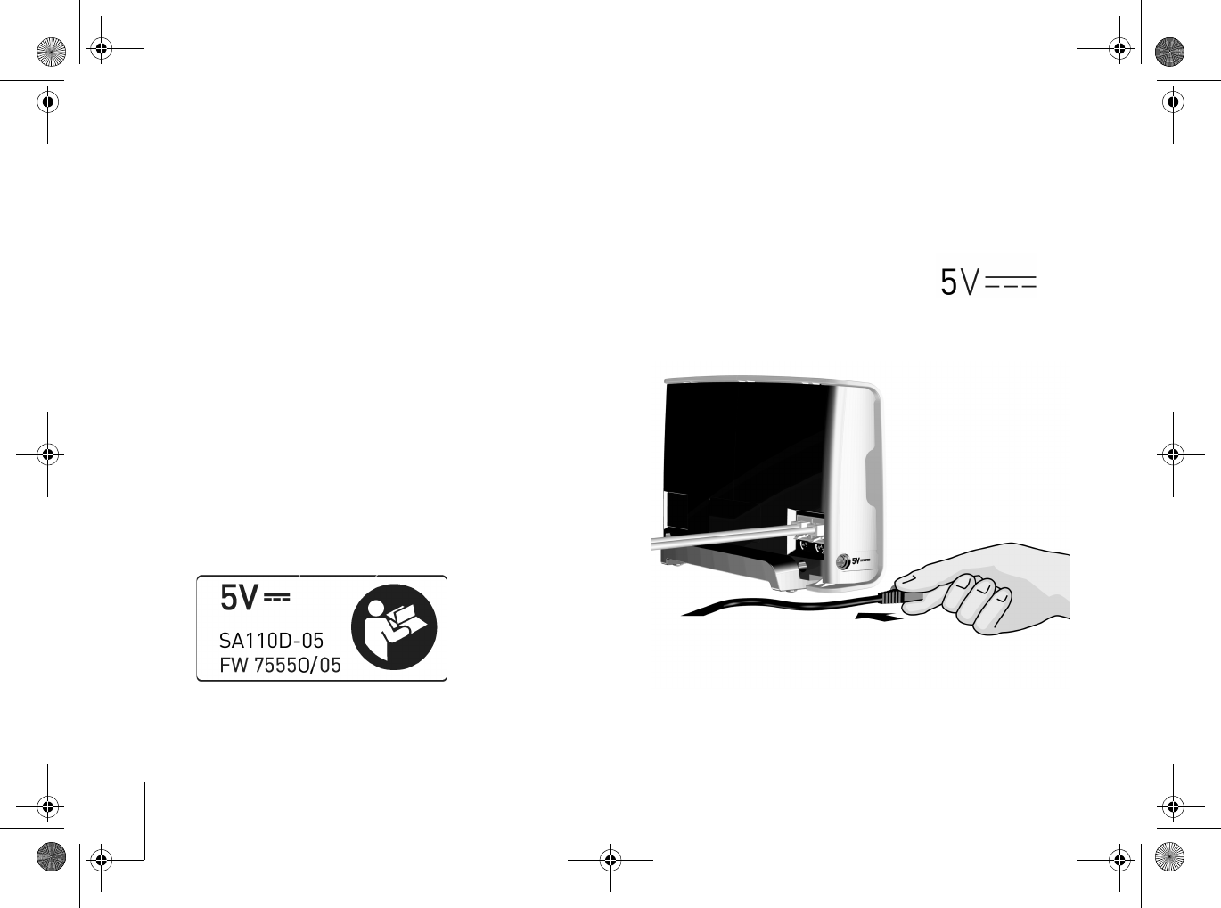
1. Connect the DC plug at the end of the
electricity cable to the port on the left side
of the CardioMessenger.
The connector port is
labeled with the following
symbol:
CM _II-S_TLine.book Page 16 Tuesday, May 6, 2008 12:56 PM
CardioMessenger II-S TLine Connection 17
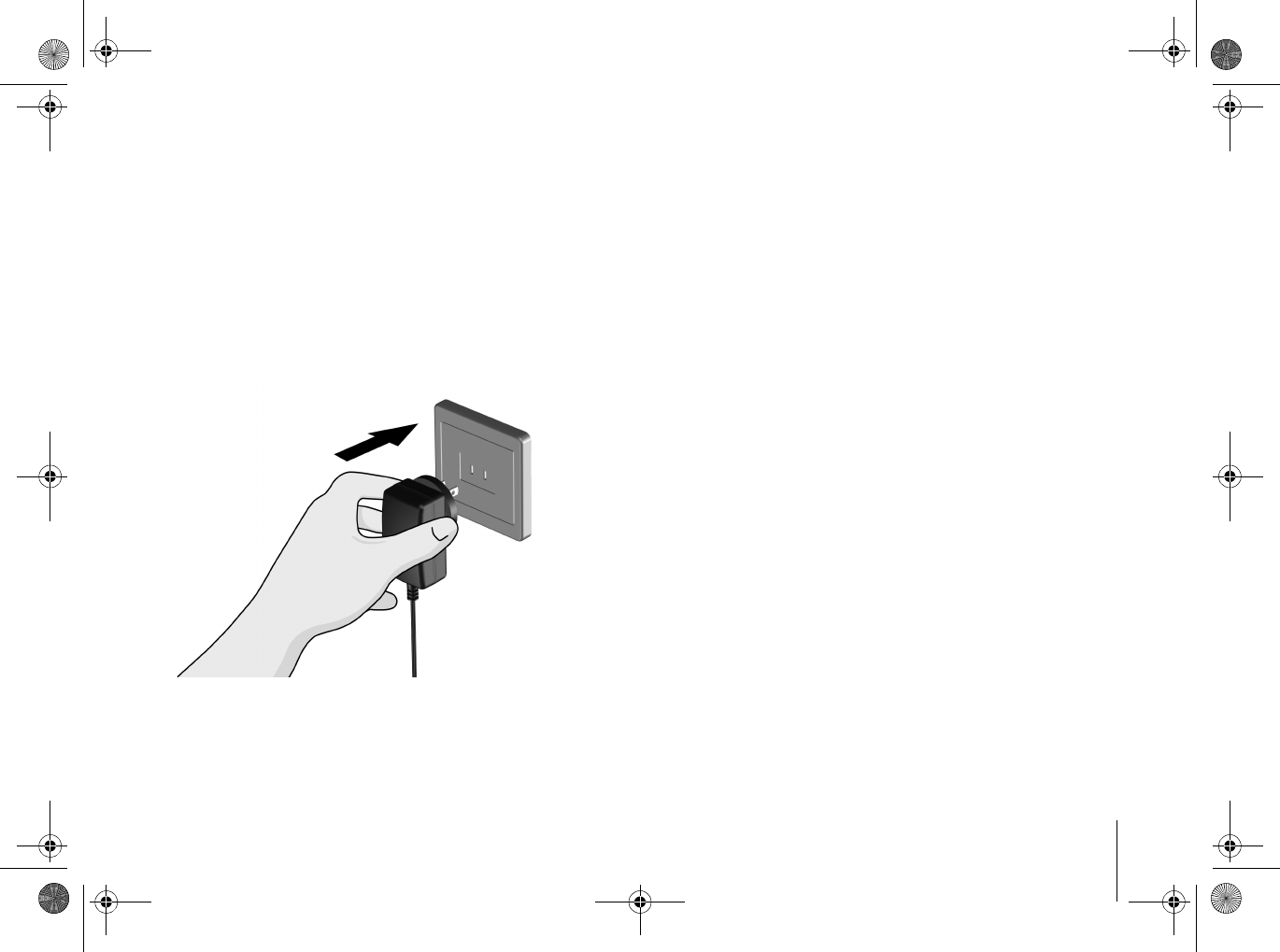
2. Connect the power supply unit to the outlet.
See that the outlet is not controlled by a
light switch. This will prevent you from
turning off the CardioMessenger
accidentally.
CM _II-S_TLine.book Page 17 Tuesday, May 6, 2008 12:56 PM
Connection
18
Self-test
The CardioMessenger automatically conducts
a self-test after being connected.
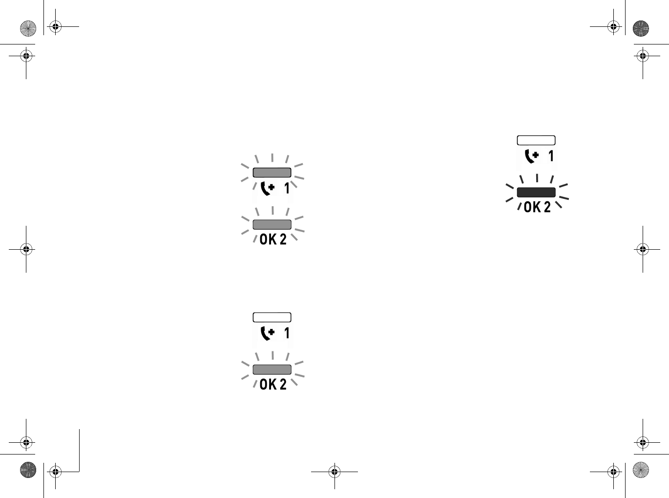
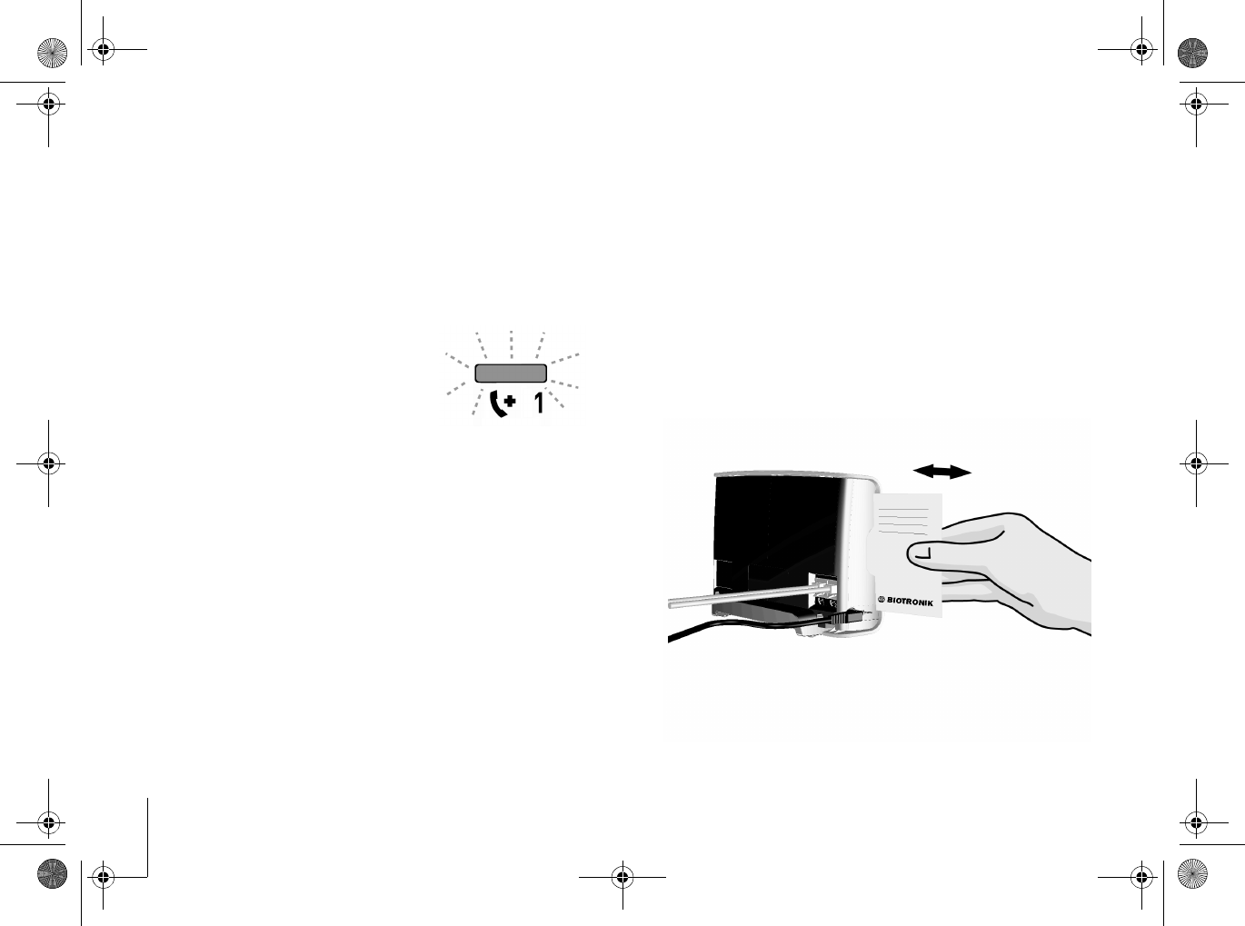
At first, both
lamps on the front
side of the
CardioMessenger
illuminate yellow
for a short while.
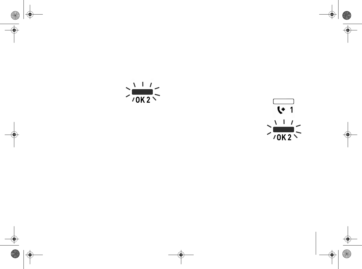
After about 10 seconds, the call back light will
turn off.
Then the
CardioMessenger checks
the connection to the
BIOTRONIK Service
Center. Only the
operating light
illuminates yellow.
The connection check can take up to
15 minutes.
As soon as the
connection has been
checked successfully,
the operating light
illuminates green.
The CardioMessenger is now ready for use.
The CardioMessenger is intended for
continuous operation. It should be connected
at all times, especially at night.
Note
It is a sign of malfunction if the operating
light remains illuminated
yellow
for more
than 15 minutes or if it does not light up at
all. For details on the subject of
"Debugging", see page 24.
CM _II-S_TLine.book Page 18 Tuesday, May 6, 2008 12:56 PM
CardioMessenger II-S TLine Connection 19
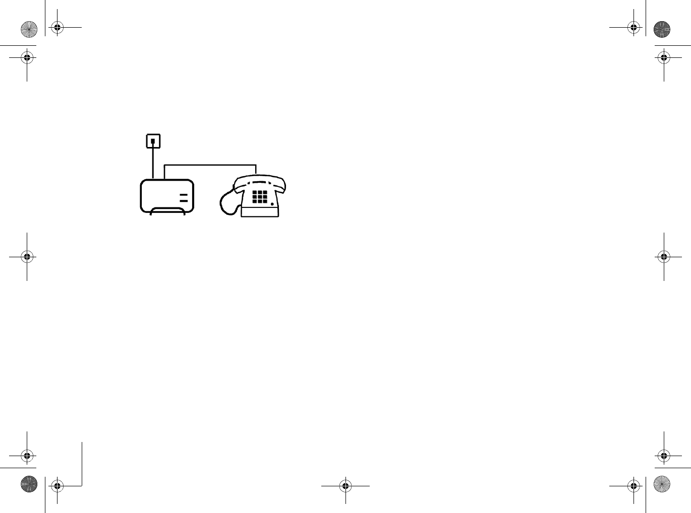
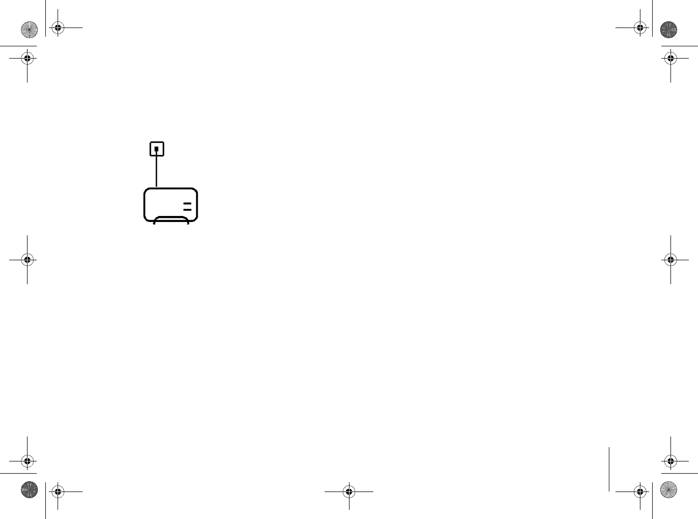
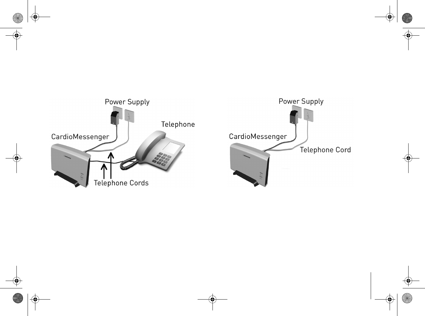
If you are operating CardioMessenger and
telephone using one telephone wall jack
(variant A), the readily connected
CardioMessenger looks as follows:
If you are operating the CardioMessenger on a
free telephone wall jack (variant B), the readily
connected CardioMessenger looks as follows:
CM _II-S_TLine.book Page 19 Tuesday, May 6, 2008 12:56 PM
Connection
20
Insert brief instructions guide
Attached to the back cover of this technical
manual is a removable instructions guide.
This guide helps to inform you quickly about
the function and colors of the lights.
Additionally, you can list your physician's
phone number at the back cover of this guide.
1. Remove the guide from this technical
manual.
2. Write your physician's or the clinic's name
and phone number on the back cover of this
guide.
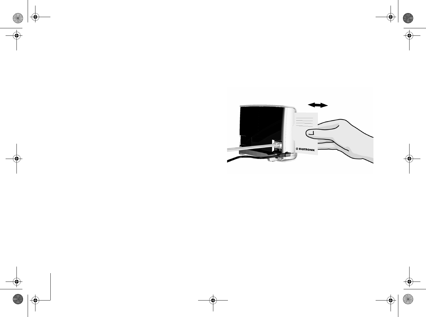
3. Insert the brief instructions guide into the
slot on the left side into the housing of the
CardioMessenger.
Now the brief instructions guide with your
physician's phone number are ready at hand.
Use it if the call back function of the
CardioMessenger was activated by your
physician. For details on the subject of "Call
back function", see page 22.
CM _II-S_TLine.book Page 20 Tuesday, May 6, 2008 12:56 PM
CardioMessenger II-S TLine Operate 21
Operate
The CardioMessenger
does not have an on/off
switch. After connecting
it, it is ready for use as
soon as the operating
light illuminates green.
It is intended for continuous operation and
should remain connected at all times,
especially at night.
The CardioMessenger automatically receives
the information from your implant and
transmits it to the BIOTRONIK Service Center.
Note
It indicates a malfunction if the operating
light illuminates
yellow
or does not light up
at all. For details on the subject of
"Debugging", see page 24.
Check lights
Check once a day whether either of the two
lights is illuminated.
Usually the operating
light illuminates green.
The call back light is
not illuminated.
Note
The functions of your implant are not
affected at any time by the
CardioMessenger, irrespective of the
illumination or blinking of the lights.
See the next page for details on the subject
"call back function".
CM _II-S_TLine.book Page 21 Tuesday, May 6, 2008 12:56 PM
Operate
22
Call back function
With the aid of the call back light, your
physician can ask you to call him. He can turn
this light on via the landline. The light will then
blink yellow for a maximum time of 3 days.
The call back light blinks
if your physician expects
your call.
Your physician will let you know whether he or
she intends to use this function in general.
Perform call back
Call your physician as soon as you realize that
the call back light is blinking.
Note
The brief instructions guide with your
physician's phone number is located in the
housing of the CardioMessenger (see
"Insert brief instructions guide", page 20).
CM _II-S_TLine.book Page 22 Tuesday, May 6, 2008 12:56 PM

CardioMessenger II-S TLine Operate 23
Turn off the call back light
To turn off the call back light, disconnect the
CardioMessenger briefly from the main supply.
1. Pull the DC plug at the end of the electricity
cable out of the port on the left side of the
CardioMessenger.
Both lights will turn off.
2. Connect the DC plug to the port again.
The CardioMessenger performs the self-test.
Afterwards, the operating light will illuminate
green and the call back light will no longer be
blinking.
Note
For details on the subject of "Connection to
the power supply", see page 16.
Switching Off the System
The CardioMessenger does not have an on/off
switch. To turn off the CardioMessenger,
disconnect it from the main supply.
1. Remove the power plug from the wall
outlet.
The operating control lamp will turn out. The
CardioMessenger is switched off.
CM _II-S_TLine.book Page 23 Tuesday, May 6, 2008 12:56 PM
Debugging
24
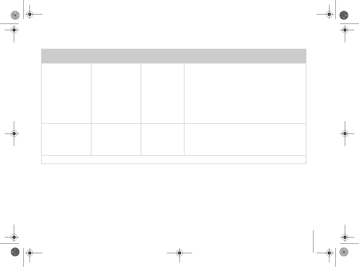
Debugging
You can identify issues with your CardioMessenger by use of the lights on the front side.
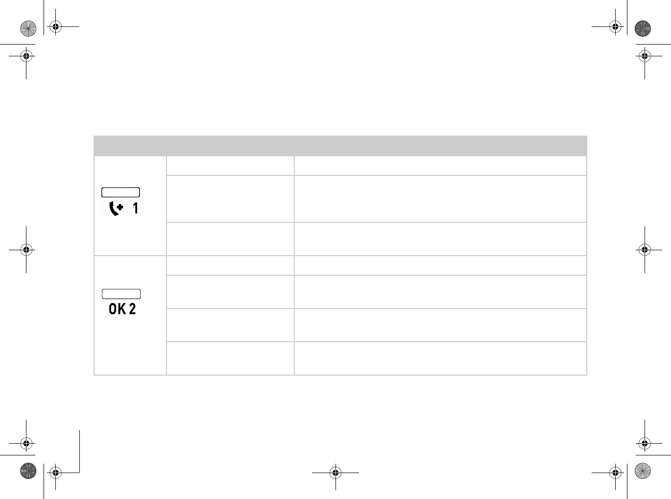
Light Behavior Operating status
Call back
light Off Normal operation;
no malfunction
Yellow blinking Your attending physician is asking for a call (For details
on the subject of "Call back function", see page 22.);
no
malfunction
Yellow blinking Error type B (both lights blink yellow): Repeat the self-
test, see next page for further details
Operating
light Off Error type A: Check the power supply, see next page
Green illumination The CardioMessenger is ready for use;
no malfunction
Yellow blinking Error type B (both lights blink yellow): Repeat the self-
test, see next page for further details
Yellow illumination Error type C (only this light illuminates): Check the
landline connection, see next page for further details
CM _II-S_TLine.book Page 24 Tuesday, May 6, 2008 12:56 PM
CardioMessenger II-S TLine Debugging 25
Error type A:
Check the power supply
The operating light is off. CardioMessenger is
not ready for use.
Check the power supply:
2
Make sure that the DC plug of the electrical
cord is plugged in tightly into the port on the
left side of the CardioMessenger.
2
Make sure that the power supply unit is
inserted properly into the wall outlet.
2
Make sure that the outlet has current, for
example by temporarily connecting the
bedside lamp to the outlet and by turning
the lamp on.
If you do not find any errors, contact your
physician.
Error type B
Repeat the self-test
Both lights blink yellow. The CardioMessenger
has not concluded the self-test. It is not yet
ready for use.
1. Remove the power supply unit from the wall
outlet.
2. Reconnect it.
The CardioMessenger restarts and performs
the self-test. Both lights will illuminate yellow.
The call back light will turn off once the self-
test is complete. The operating light will
remain illuminated yellow. Next, the
CardioMessenger checks the connection to the
BIOTRONIK Service Center. The operating
light switches to green once the connection
test is sucessful. The CardioMessenger is now
ready for use.
CM _II-S_TLine.book Page 25 Tuesday, May 6, 2008 12:56 PM

Debugging
26
If both lights stay permanently illuminated
yellow, the CardioMessenger is defective.
Return it to your physician.
Note
The connection check can take up to
15 minutes.
Error type C
Check the landline connection
The operating light illuminates yellow
continuously (longer than 15 minutes). The call
back light is off. CardioMessenger cannot
connect to the BIOTRONIK Service Center.
1. Make sure that the one end of the telephone
cable is properly inserted into the telephone
wall jack.
2. Make sure that the other end of the
telephone cable is properly inserted into
phone inlet 1 on the back of the
CardioMessenger.
3. Check whether the telephone line is
available by lifting and listening to the
receiver. You should be able to hear the
normal dial tone.
4. Remove the power supply unit from the wall
outlet.
5. Reconnect it.
CM _II-S_TLine.book Page 26 Tuesday, May 6, 2008 12:56 PM

CardioMessenger II-S TLine Debugging 27
The CardioMessenger restarts and performs
the self-test. It checks the connection to the
BIOTRONIK Service Center. The operating
light switches to green once the connection
test is sucessful. The CardioMessenger is now
ready for use.
Note
The connection check can take up to
15 minutes.
Note
The CardioMessenger has been designed
for use with an analog landline. Correct
operation cannot be ensured if using a
digital landline. If you are unsure what kind
of landline you are using, please contact
your telephone provider.
If the operating light remains continuously
illuminated yellow, contact your physician.
CM _II-S_TLine.book Page 27 Tuesday, May 6, 2008 12:56 PM

Cleaning, maintenance, and disposal
28
Cleaning, maintenance, and disposal
Cleaning
2
Keep the CardioMessenger clean and away
from dirty or dusty environments.
2
Use a soft, lint-free cloth for cleaning.
Caution!
Disconnect the CardioMessenger from the
main power supply before attempting to
clean it with a moist cloth.
2
Use a cloth wetted with water for cleaning.
However, avoid bringing the
CardioMessenger into direct contact with
water or solvents.
Maintenance
The CardioMessenger is intended for
continuous, automatic operation. Once
correctly installed, ongoing actions by you are
typically not required (e.g., no maintenance is
required).
In continuous operation, the longevity of the
contained button cell corresponds to the
longevity of the CardioMessenger.
CM _II-S_TLine.book Page 28 Tuesday, May 6, 2008 12:56 PM
CardioMessenger II-S TLine Cleaning, maintenance, and disposal 29
Disposal
Do not dispose the CardioMessenger in the
usual household trash.
CardioMessenger and the power supply unit
contain materials that must be correctly
disposed of in accordance with environmental
protection regulations.
If no longer required or if defective, please
return the CardioMessenger and all other
supplied parts to the physician. Your physician
will return all parts to BIOTRONIK.
BIOTRONIK ensures the disposal in
accordance with the national design of the
European guideline 2002/96/EC on electric and
electronic used devices (WEE).
CM _II-S_TLine.book Page 29 Tuesday, May 6, 2008 12:56 PM
Precautionary measures
30
Precautionary measures
The CardioMessenger is a medical device and
therefore complies with strict requirements for
their development, manufacture and testing.
Please take the following precautions:
Warning!
The device must be located outside the
patient's vicinity if the intended user is to be
introduced to the device in the hospital.
These legal requirements apply for electrical
devices in hospitals and do not apply when the
CardioMessenger is used at home.
Warning!
Use the CardioMessenger only if it is
undamaged. Return a damaged
CardioMessenger to your physician.
Warning!
Use only the original parts included (for
details, see "Technical data", page 37).
Other equipment may impair proper
functioning of the CardioMessenger and
increase the emitted interference and the
device's susceptibility to interference.
The label on the back side of the
CardioMessenger indicates the approved
power supply:
Caution!
Federal (U.S.A.) law restricts this device to
sale by, or on the order of, a physician (or
properly licensed practitioner).
CM _II-S_TLine.book Page 30 Tuesday, May 6, 2008 12:56 PM

CardioMessenger II-S TLine Precautionary measures 31
Caution!
Protect the CardioMessenger from:
– Water and high humidity
– Temperatures above 40 °C (104 °F) (for
example from direct sunlight and strong
halogen spotlights)
– Temperatures below 10 °C (50 °F)
– Solvents, acids, detergents, and lyes
Caution!
The CardioMessenger may only be opened
and repaired by authorized trained
personnel.
CM _II-S_TLine.book Page 31 Tuesday, May 6, 2008 12:56 PM

Precautionary measures
32
CM _II-S_TLine.book Page 32 Tuesday, May 6, 2008 12:56 PM
CardioMessenger II-S TLine Guidelines 33
Guidelines
USA
FCC RF Exposure Requirements
Your implant is equipped with a radio
frequency (RF) transceiver for wireless
communications to the CardioMessenger.
These messages are transmitted via an RF
assigned by the Federal Communications
Commission's (FCC) Medical Implant
Communications Service (MICS)
1)
.
This device may not interfere with stations
operating in the 400.150–406.000 MHz band in
the Meteorological Aids, Meteorological
Satellite, and Earth Exploration Satellite
Services and must accept any interference
received, including interference that may
cause undesired operation.
This device complies with Part 15 of the FCC
Rules. Operation is subject to the following two
conditions: (1) this device may not cause
harmful interference, and (2) this device must
accept any interference received, including
interference that may cause undesired
operation.
This transceiver shall be used only in
accordance with the FCC rules governing the
Medical Implant Communications Service.
Analog and digital voice communications are
prohibited. Although this transceiver has been
approved by the Federal Communications
Commission, there is no guarantee that it will
not receive interference or that any particular
transmission from this transceiver will be free
from interference.
1) Federal Communications Commission for Medical Implant Communications Service
CM _II-S_TLine.book Page 33 Tuesday, May 6, 2008 12:56 PM

Guidelines
34
The FCC ID number for the CardioMessenger
is QRICM08V-1.
The ACTA ID number for the cable modem is
AU7MMO1BMT5656SMI for the
CardioMessenger II-S/1 and AU7MDO4B2456
for the CardioMessenger II-S/2.
Statement according to FCC part 2.1091:
The internal/external antennas used for this
mobile transmitter must provide a separation
distance of at least 20 cm from all persons and
must not be co-located or operating in con-
junction with any other antenna or transmitter.
Statement according to FCC part 15.105:
NOTE: This equipment has been tested and
found to comply with the limits for a Class B
digital device, pursuant to Part 15 of the FCC
Rules. These limits are designed to provide
reasonable protection against harmful inter-
ference in a residential installation. This equip-
ment generates, uses and can radiate radio
frequency energy and, if not installed and used
in accordance with the instructions, may cause
harmful interference to radio communications.
However, there is no guarantee that interfer-
ence will not occur in a particular installation.
If this equipment does cause harmful interfer-
ence to radio or television reception, which can
be determined by turning the equipment off
and on, the user is encouraged to try to correct
the interference by one or more of the follow-
ing measures:
— Reorient or relocate the receiving antenna.
— Increase the separation between the equip-
ment and receiver.
— Connect the equipment into an outlet on a
circuit different from that to which the
receiver is connected.
— Consult the dealer or an experienced radio/
TV technician for help.
Changes or modifications not expressly
approved by this company could void the user's
authority to operate the equipment.
CM _II-S_TLine.book Page 34 Tuesday, May 6, 2008 12:56 PM

CardioMessenger II-S TLine Guidelines 35
Adress of responsible party:
BIOTRONIK, Inc.
6024 SW Jean rd. Bldg. B
Lake Oswego, OR 97035
Phone (800) 547-0394
Canada
The CardioMessenger is registered at Industry
Canada with the following number: IC: 4708A-
CM08V1.
The cable modem is registered at Industry
Canada with the following number: IC: 125A-
0015 or 125A-0008.
The term "IC:" before the certification/
registration number only signifies that the
Industry Canada technical specifications were
met.
This device may not interfere with stations
operating in the 400.150-406.000 MHz band in
the meteorological aids, meteorological-
satellite, and earth exploration-satellite
services and must accept any interference
received, including interference that may
cause undesired operation.
CM _II-S_TLine.book Page 35 Tuesday, May 6, 2008 12:56 PM
Guidelines
36
Electromagnetic compatibility
Note
The CardioMessenger is protected from
disturbances resulting from
electromagnetic interference, electrostatic
discharges, and other sources – including
interference induced by cables. Interfering
emissions from the CardioMessenger have
been minimized. The CardioMessenger
therefore meets the requirements of EN
60601-1-2 in every respect.
Warning!
Other equipment, including portable and
mobile RF radiocommunications equipment
may interfere with the CardioMessenger,
even if this equipment complies with CISPR
emission requirements. However, this
possible interference does not affect the
implant functionality.
Warranty
The CardioMessenger and all original
components by BIOTRONIK are not subject to
warranty when used improperly or stored and
transported incorrectly. Use only the original
packaging when shipping the device.
CM _II-S_TLine.book Page 36 Tuesday, May 6, 2008 12:56 PM

CardioMessenger II-S TLine Technical data 37
Technical data
General
2
Operating mode: Continuous operation
Permissible Environmental Conditions
2
Operating temperature: +10°C (50°F) to +40
C (104°F)
2
Storage and transport temperature:
-10°C (14°F) to + 60°C (140°F)
2
Relative humidity:
30% to 75% (non-condensing)
2
Atmospheric pressure: 700 hPa to 1060 hPa
CardioMessenger
2
Dimensions (WxHxD):
approx. 203 x 136.5 x 80 mm
2
MICS: Modulation FSK
2
MICS frequencies: 402–405 MHz,
9 channels, 300 kHz frequency range
2
MICS transmission power: 25 µW EIRP
Telephone cable
2
Type: VK-117
2
Length: approx. 2.5 m (8.2 ft)
2
Outlet: Rj-11
CM _II-S_TLine.book Page 37 Tuesday, May 6, 2008 12:56 PM
Technical data
38
Power supply unit
2
Type: FRIWO MMP 15 FW7555O/05
2
Dimensions (WxHxD):
approx. 51.5 x 87.5 x 34 mm
2
DC plug output:
Outer diameter 5.5 mm (mass),
Inner diameter 2.1 mm (plus)
2
Input voltage:
100–240 V ~ 50–60 Hz 400 mA
2
Output voltage:
5VDC ± 5%, 2.4A/12W
2
Safety class: II
or:
2
Type: Nordic Power (SAC) SA110D-05
2
Dimensions (WxHxD): approx. 69 x 45 x 35
mm
2
DC plug output:
Outer diameter 5.5 mm (mass),
Inner diameter 2.1 mm (plus)
2
Input voltage:
100–240 V ~ 50–60 Hz 300 mA
2
Output voltage:
5.1VDC ± 5%, 2A/10.2W
2
Safety class: II
Technical manual
2
Technical manual with brief instructions
guide CardioMessenger II-S TLine
CM _II-S_TLine.book Page 38 Tuesday, May 6, 2008 12:56 PM
CardioMessenger II-S TLine Appendix 39
Appendix
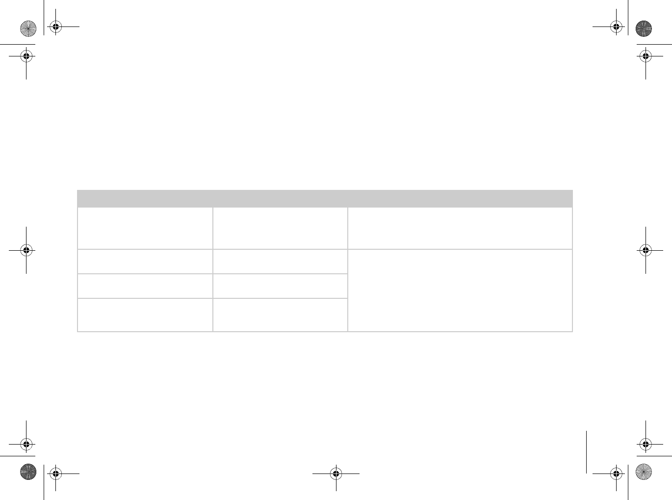
Electromagnetic emitted interference according to IEC 60601-1-2
The CardioMessenger is suitable for operation in the indicated electromagnetic environment. The
customer and/or operator of the CardioMessenger should make sure that it is used in an electroma-
gnetic environment as described below.
Measuring the interference Compliance Guidelines for the electromagnetic environment
High-frequency interference accor-
ding to CISPR 11 Group 1 The CardioMessenger uses RF energy only for its internal
function. Therefore, the HF interference is very low and not
likely to cause any interference in nearby electronic equip-
ment.
High-frequency interference accor-
ding to CISPR 11 Class B The CardioMessenger is suitable for use in all areas, including
living space and those areas that are directly connected to a
public power supply system that also supplies buildings inten-
ded for residential purposes.
Interference of harmonics according
to IEC 61000-3-2 Class A according to IEC 61000-3-2
Voltage fluctuations/flicker emissi-
ons according to
IEC 61000-3-3
Complies
CM _II-S_TLine.book Page 39 Tuesday, May 6, 2008 12:56 PM
Appendix
40
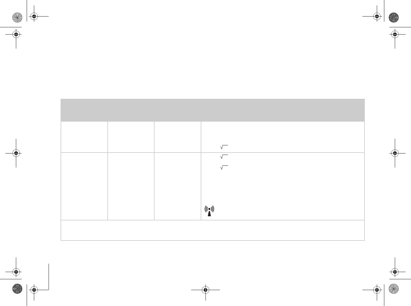
Electromagnetic emitted interference according to IEC 60601-1-2
The CardioMessenger is suitable for operation in the indicated electromagnetic environment. The
customer and/or operator of the CardioMessenger should make sure that it is used in an electroma-
gnetic environment as described below.
Testing resis-
tance to interfe-
rence
Test level accor-
ding to
IEC 60601-1-2
Conformance
level Guidelines for the electromagnetic environment
Conducted RF
interference accor-
ding to
IEC 61000-4-6
3Veff
150 kHz to 80 MHz Same as test level The minimum distance of the CardioMessenger from portable and mobile
radio devices, including the cables, should correspond to the recommen-
ded safe distance that is calculated according to the equation for the suita-
ble transmission frequency. Recommended safe distance:
D= 1,17
Radiated RF inter-
ference according
to IEC
61000-4-3
3V/m
80 MHz to 2.5 GHz Same as test level D= 1,17 for 80 to 800 MHz
D= 2,34 for 800 MHz to 2.5 GHz with P as the nominal output of the
transmitter in Watts (W) according to the information from the transmitter
manufacturer, and d as the recommended safe distance in meters (m).
The field strength of stationary transmitting devices should be measured
on sitea) and must be lower than the compliance level at all frequenciesb).
Interference can be generated when the CardioMessenger is close to
devices that have the following warning sign:
Note: The higher frequency range applies at 80MHz and at 800MHz.
Note: These guidelines may not be applicable in all cases. The spread of electromagnetic waves is influenced by absorption and reflection from
buildings, objects, and humans.
P
P
P
CM _II-S_TLine.book Page 40 Tuesday, May 6, 2008 12:56 PM

CardioMessenger II-S TLine Appendix 41
a) Field strengths from fixed transmitters, such as base stations for radio (cellular(/cordless) telephones and land mobile radios, amateur radio,
AM and FM radio broadcast and TV broadcast cannot be predicted theoretically with accuracy.
To assess the electromagnetic environment due to fixed RF transmitters, an electromagnetic site survey should be considered. If the measu-
red field strength in the location in which the CardioMessenger is used exceeds the applicable RF compliance level above, the Cardio-
Messenger should be observed to verify normal operation. If abnormal performance is observed, additional measures may be necessary,
such as re-orienting or relocating the CardioMessenger.
b) Above the frequency range of 150KHz to 80MHz, ensure that field strengths are less than 3V/m.
CM _II-S_TLine.book Page 41 Tuesday, May 6, 2008 12:56 PM
Appendix
42
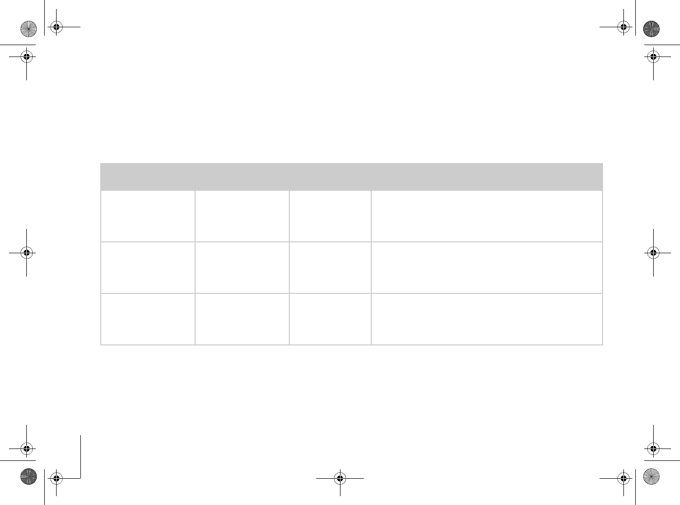
Electromagnetic emitted interference according to IEC 60601-1-2
The CardioMessenger is suitable for operation in the indicated electromagnetic environment. The
customer and/or operator of the CardioMessenger should make sure that it is used in an electroma-
gnetic environment as described below.
Checking
immunity to noise Test level according
to IEC 60601-1-2 Conformance
level Guidelines for the electromagnetic environment
Discharge of static elec-
tricity (ESD)
According to IEC 61000-
4-2
± 6 kV contact discharge
±8 kV air discharge
Same as test level Floors should be made of wood or cement, or have ceramic
tiles. When the floor consists of a synthetic material, the rela-
tive humidity must be at least 30%.
Rapid transient electri-
cal disturbances/bursts
According to IEC 61000-
4-4
± 2 kV for
power supply lines
± 1 kV for input/output
lines
Same as the test
level The quality of the supply voltage should correspond to that in a
typical business and/or hospital.
Surge
According to IEC 61000-
4-5
±1kV normal mode
voltage
± 2 kV common mode
voltage
Same as the test
level The quality of the supply voltage should correspond to that in a
typical business and/or hospital.
CM _II-S_TLine.book Page 42 Tuesday, May 6, 2008 12:56 PM
CardioMessenger II-S TLine Appendix 43
Voltage dips, brief inter-
ruptions and fluctuati-
ons in the supply
voltage
According to IEC 61000-
4-11
‹ 5% UT for
1/2 cycle
(› 95% drop)
40% UT for 5 periods
(60% drop)
70% UT for 25 periods
(30% drop)
‹ 5% UT for 5 s
(› 95% drop)
Same as the test
level The quality of the supply voltage should correspond to that in a
typical business and/or hospital.
The CardioMessenger is powered by a battery. An interruption
in the supply voltage to the power supply unit will not impair the
functioning of the CardioMessenger.
Magnetic field at the
supply frequencies (50/
60 Hz)
According to IEC 61000-
4-8
3A/m Same as the test
level The magnetic field strength should correspond to the typical
value in business and hospital environments.
Comment: UT is the mains alternating voltage before applying the test levels.
Checking
immunity to noise Test level according
to IEC 60601-1-2 Conformance
level Guidelines for the electromagnetic environment
CM _II-S_TLine.book Page 43 Tuesday, May 6, 2008 12:56 PM
Appendix
44
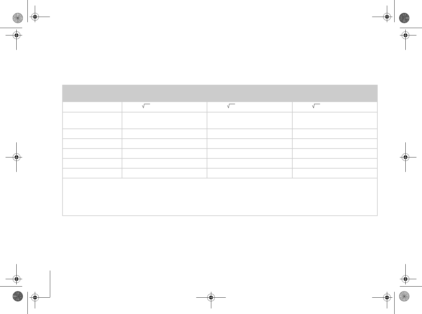
Recommended separation distances between portable and mobile RF communications
equipment and the CardioMessenger
Transmission fre-
quency 150 kHz to 80 MHz 80 MHz to 800 MHz 800 MHz to 2.5 GHz
Equation D= 1,17 D= 1,17 D= 2,34
Rated power
of transmitter (W) Safe distance (m) Safe distance (m) Safe distance (m)
0.01 0.12 0.12 0.24
0.1 0.37 0.37 0.74
1 1.17 1.17 2.34
10 3.7 3.7 7.4
100 11.7 11.7 23.4
For transmitters whose maximum nominal output is not indicated in the above table, the distance can be calculated using the equation in the
column, where P is the maximum nominal output of the transmitter in Watts (W) according to the transmitter’s manufacturer.
Note: The higher frequency range applies at 80MHz and at 800MHz.
Note: These guidelines may not be applicable in all cases. The propagation of electromagnetic values is affected by absorption and reflection by
structures, objects and people.
P P P
CM _II-S_TLine.book Page 44 Tuesday, May 6, 2008 12:56 PM

CardioMessenger II-S TLine Index 45
Index
A
Ambient conditions . . . . . . . . . . . . . . . . . . 37
Appendix . . . . . . . . . . . . . . . . . . . . . . . . . . . 39
B
Bedside table . . . . . . . . . . . . . . . . . . . . . . . . 7
BIOTRONIK Service Center . . . . . . . . . . 4, 21
Blinking . . . . . . . . . . . . . . . . . . . . . . . . 22, 24
Brief instructions guide . . . . . . . . . . . . 20, 22
Broken CardioMessenger . . . . . . . . . . . . . 30
C
Call back function . . . . . . . . . . . . . . . . . . . 22
Call back light . . . . . . . . . . . . . . . . . . . 18, 22
Call your physician . . . . . . . . . . . . . . . . . . 22
Care . . . . . . . . . . . . . . . . . . . . . . . . . . . . . . 28
Check the landline connection . . . 11, 18, 26
Check the telephone connection . . . . . . . 11
Checking the power supply . . . . . . . . . . . . 25
Clean it . . . . . . . . . . . . . . . . . . . . . . . . . . . . 28
Cleaning . . . . . . . . . . . . . . . . . . . . . . . . . . . 28
Connection to the landline . . . . . . . . . . 8, 19
Connection to the power supply . . . . 16, 19
D
Damaged CardioMessenger . . . . . . . . . 5, 30
DC plug . . . . . . . . . . . . . . . . . . . . . . . 5, 23, 38
Debugging . . . . . . . . . . . . . . . . . . . . . . . . . 24
Defective CardioMessenger . . . . . . . . . . . 30
Disposal . . . . . . . . . . . . . . . . . . . . . . . . . . . 29
Distance to the implant . . . . . . . . . . . . . . . 7
E
Electricity cable . . . . . . . . . . . . . . . . 5, 16, 23
Electromagnetic Compatibility . . . . . . . . 36
Electromagnetic emitted interference . . 39
G
Green light . . . . . . . . . . . . . . . . . . . 18, 21, 24
Guidelines Canada . . . . . . . . . . . . . . . . . . 35
Guidelines USA . . . . . . . . . . . . . . . . . . . . . 33
CM _II-S_TLine.book Page 45 Tuesday, May 6, 2008 12:56 PM

Index
46
H
Home Monitoring . . . . . . . . . . . . . . . . . . . . .3
Hospital . . . . . . . . . . . . . . . . . . . . . . . . . . . .30
I
Illumination . . . . . . . . . . . . . . . . . . . . . . . . .24
Implant . . . . . . . . . . . . . . . . . . . . . . . . . . . 3, 7
L
Landline connection . . . . . . . . . . . . . . . . . . .4
Light 1 . . . . . . . . . . . . . . . . . . . .18, 21, 22, 24
Light 2 . . . . . . . . . . . . . . . . . . . . . . . . . .18, 24
M
Maintenance . . . . . . . . . . . . . . . . . . . . . . . .28
O
Operate . . . . . . . . . . . . . . . . . . . . . . . . . . . .21
Operating light . . . . . . . . . . . . . . . .18, 21, 24
Original parts . . . . . . . . . . . . . . . . . . . . .5, 37
Outlet . . . . . . . . . . . . . . . . . . . . . . . . . . . . . .17
P
Package Contents . . . . . . . . . . . . . . . . . . . . 5
Perform call back . . . . . . . . . . . . . . . . . . . 22
Phone inlet 1 . . . . . . . . . . . . . . . . . . . . . 9, 13
Phone inlet 2 . . . . . . . . . . . . . . . . . . . . . . . 10
Physician call back light . . . . . . . . . . . . . . 24
Physician's phone number . . . . . . . . . 20, 22
Port for power connection . . . . . . . . . . . . 16
Power connection port . . . . . . . . . . . . . . . 16
Power supply unit . . . . . . . . . . . . . . 5, 16, 38
Precautionary measures . . . . . . . . . . . . . . 30
R
Ready-for-service status . . . . . . . . . . . . . 21
Recommended separation distances . . . 44
Repair . . . . . . . . . . . . . . . . . . . . . . . . . . . . . 31
S
Safety instructions . . . . . . . . . . . . . . . . . . . 30
Sealing plug . . . . . . . . . . . . . . . . . . . 9, 10, 13
Self-test . . . . . . . . . . . . . . . . . . . . . . . . 18, 25
Setup . . . . . . . . . . . . . . . . . . . . . . . . . . . . . . . 7
Suitable installation location . . . . . . . . . . . 7
CM _II-S_TLine.book Page 46 Tuesday, May 6, 2008 12:56 PM

CardioMessenger II-S TLine Index 47
Switch off the system . . . . . . . . . . . . . . . . 23
Switching on the system . . . . . . . . . . . 21, 23
T
Technical data . . . . . . . . . . . . . . . . . . . . . . 37
Telephone cable . . . . . . . . . . 5, 10, 11, 14, 37
Telephone wall jack . . . . . . . . 8, 9, 11, 13, 14
Transmitter of the implant . . . . . . . . . . . 3, 7
Turn off the call back light . . . . . . . . . . . . 23
U
Unsuitable installation location . . . . . . . . . 7
W
Warranty . . . . . . . . . . . . . . . . . . . . . . . . . . . 36
Y
Yellow light . . . . . . . . . . . . . . . . . . . 18, 22, 24
CM _II-S_TLine.book Page 47 Tuesday, May 6, 2008 12:56 PM