BIOTRONIK SE and KG LUMAXT Implantable Defibrillator User Manual UserMan
BIOTRONIK SE & Co. KG Implantable Defibrillator UserMan
UserManual.wiki
>
BIOTRONIK SE and KG
>
LUMAXT User Manual
UserMan
Navigation menu
Upload a User Manual
Namespaces
Wiki Guide
HTML
PDF
Info
Views
User Manual
Discussion / Help
Navigation
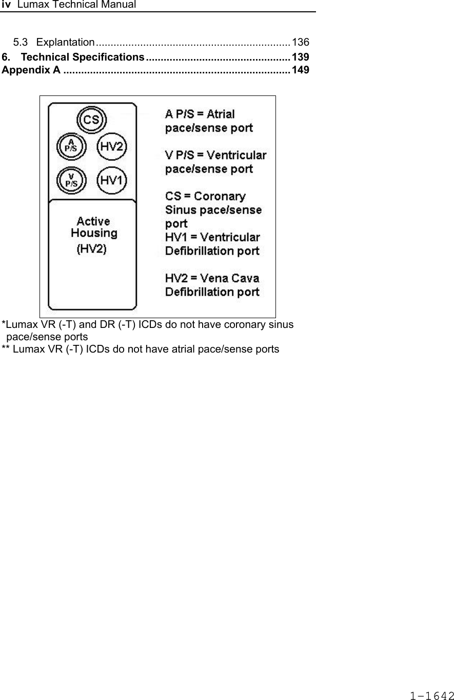
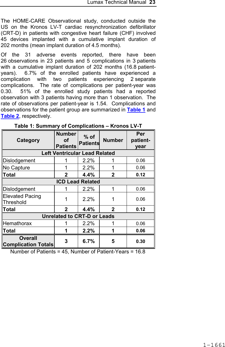
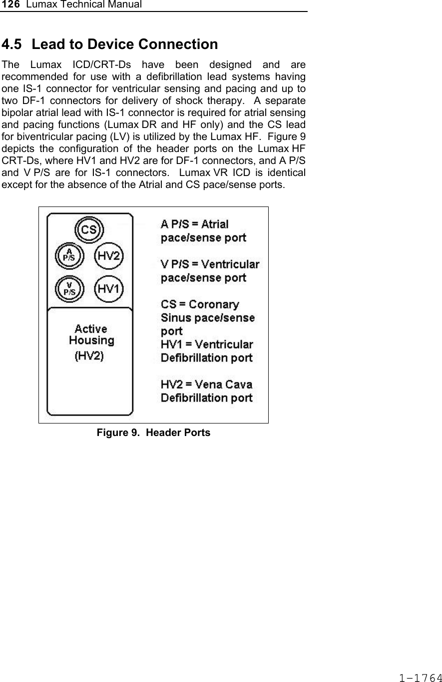
![Lumax Technical Manual 7 • Lumax DR provides dual chamber rate adaptive bradycardia pacing support. The ICD uses atrial and ventricular sensing/pacing leads to provide enhanced atrial and ventricular tachyarrhythmia discrimination through BIOTRONIK’s SMART DetectionTM algorithm. • Lumax DR-T In addition to the functionality found with the DR model it also has the added functionality of BIOTRONIK’s Home Monitoring system. The Home Monitoring System enables automatic exchange of information about a patient’s cardiac status from the implant to the physician remotely. • Lumax VR provides single chamber rate adaptive bradycardia pacing support as well as tachyarrhythmia detection and therapy. • Lumax VR-T In addition to the functionality found with standard VR model it also has the added functionality of BIOTRONIK’s Home Monitoring system. The Home Monitoring System enables automatic exchange of information about a patient’s cardiac status from the implant to the physician remotely. The 300 and 340 reference for each of the above-described models denote the maximum programmable shock energy of 30 joules and 40 joules, respectively. All members of the Lumax device family have two DF-1 defibrillation/ cardioversion ports. In addition, the Lumax HF (-T) models have three IS-1 pacing/sensing header ports. The Lumax DR (-T) models have two IS-1 pacing/sensing header ports. The Lumax VR (-T) models have one IS-1 pacing/sensing header ports. IS-1 refers to the international standard whereby leads and generators from different manufacturers are assured a basic fit [Reference ISO 5841-3:1992]. DF-1 refers to the international standard for defibrillation lead connectors [Reference ISO 11318:1993]. 1-1645](https://usermanual.wiki/BIOTRONIK-SE-and-KG/LUMAXT/User-Guide-710245-Page-9.png)


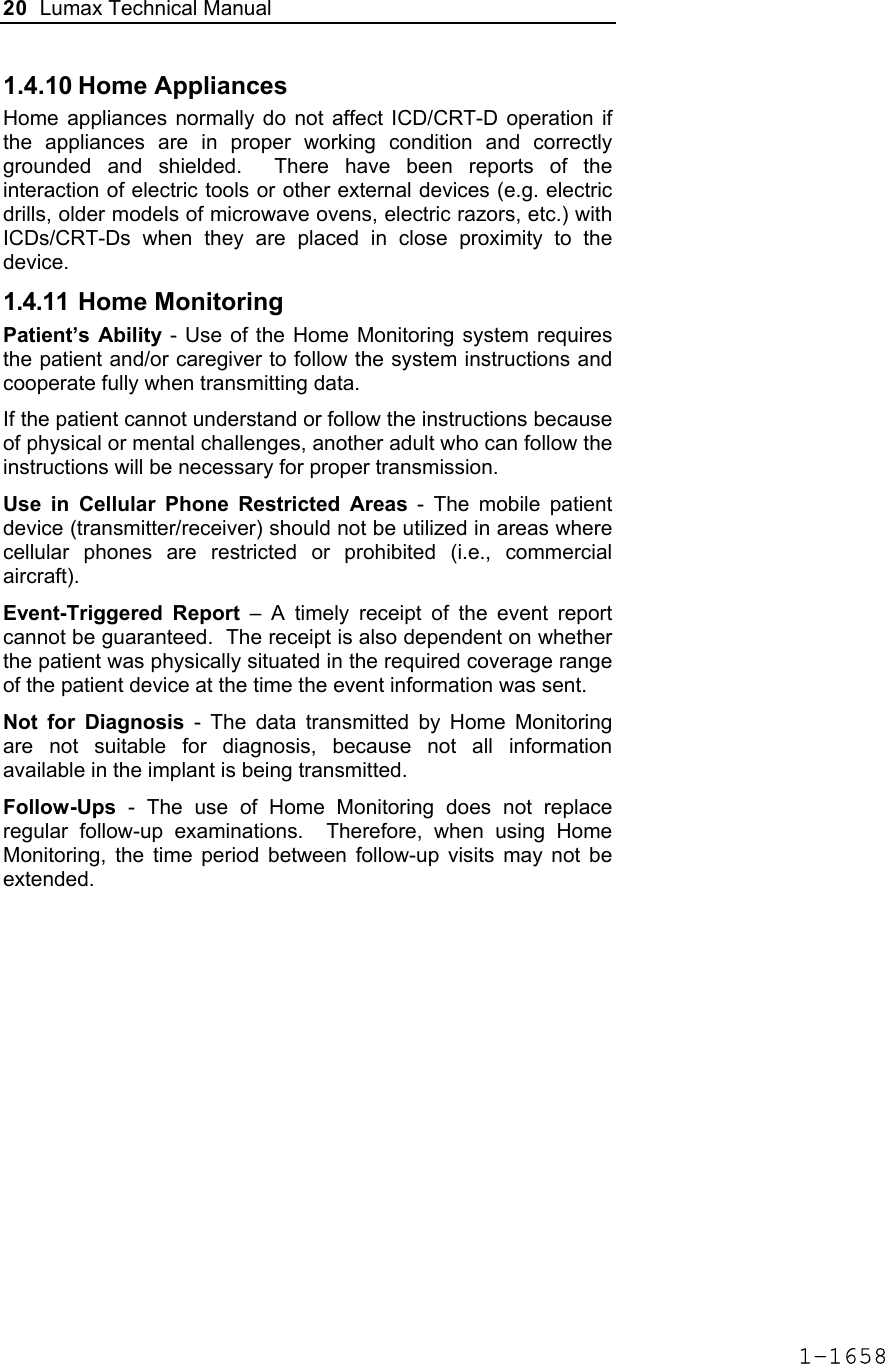
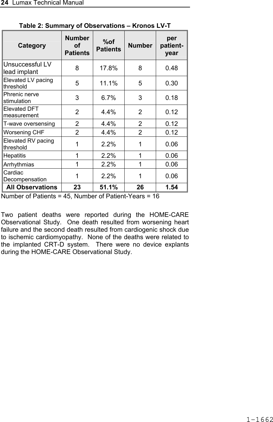

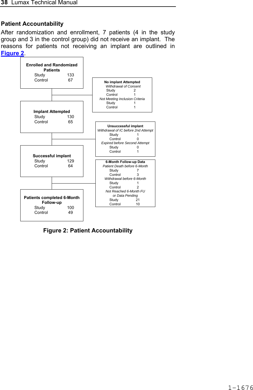
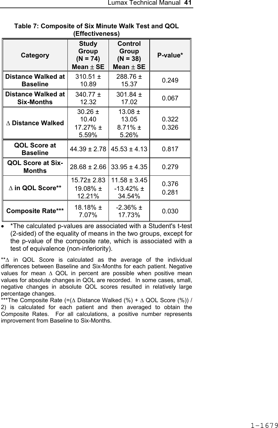
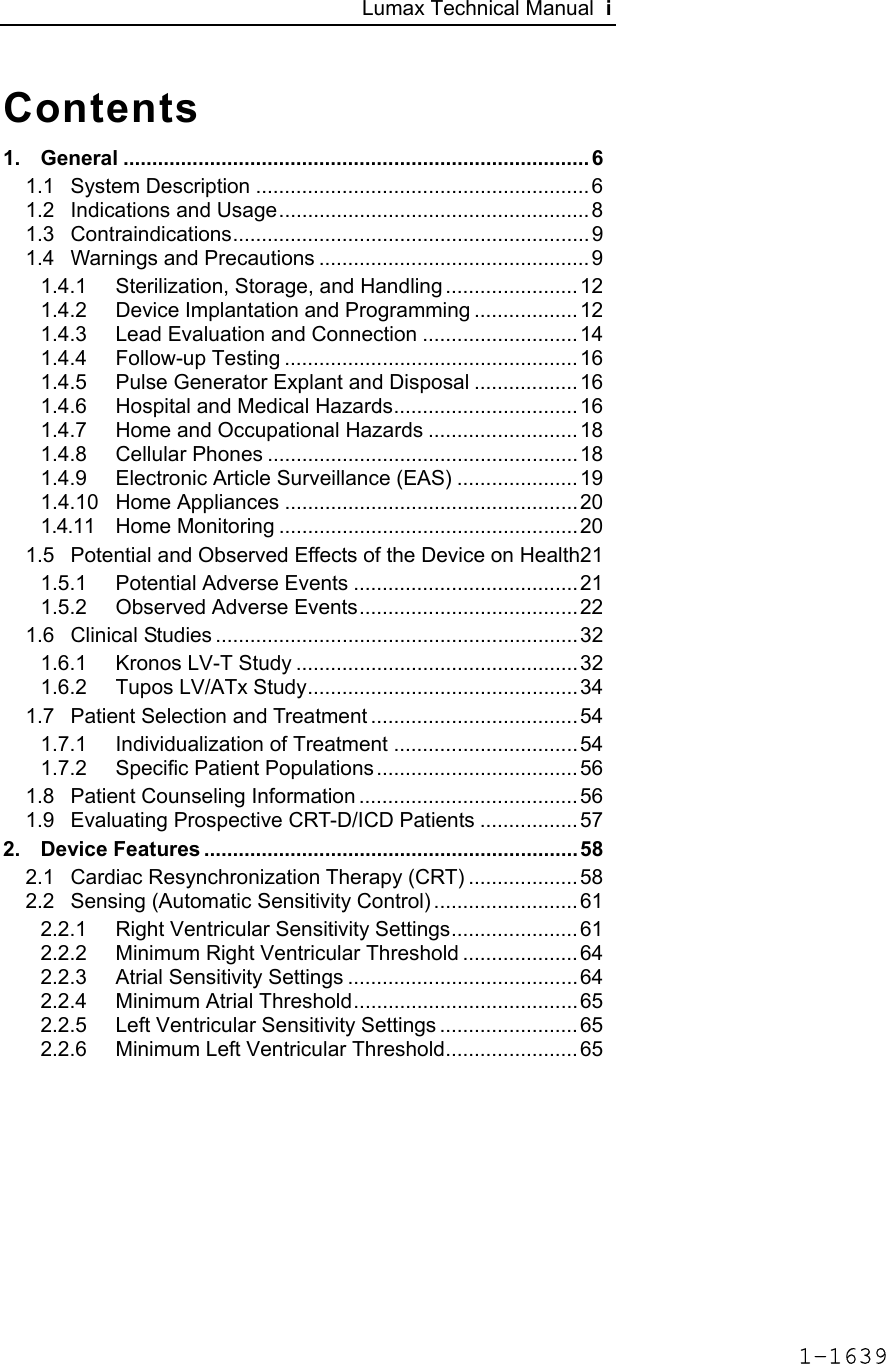
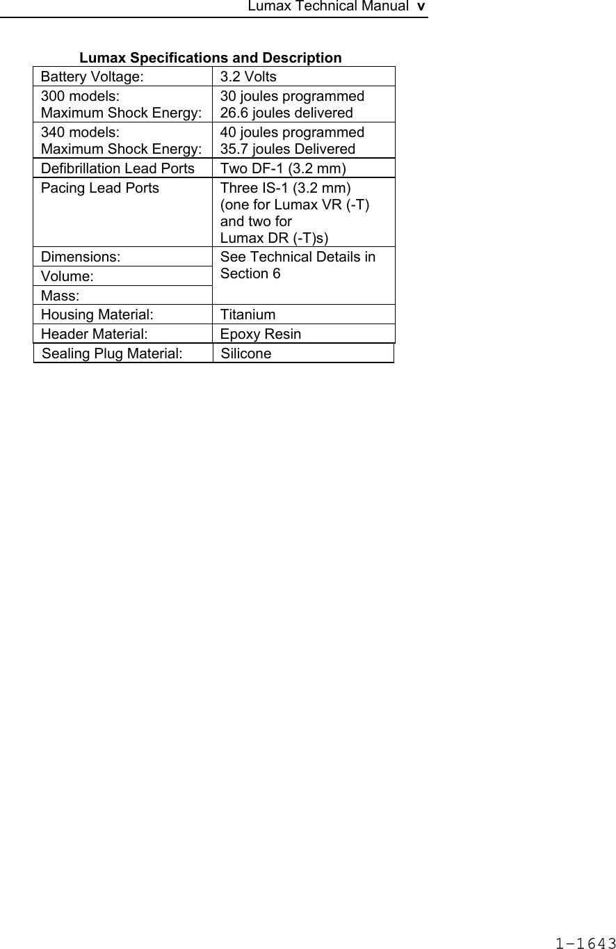
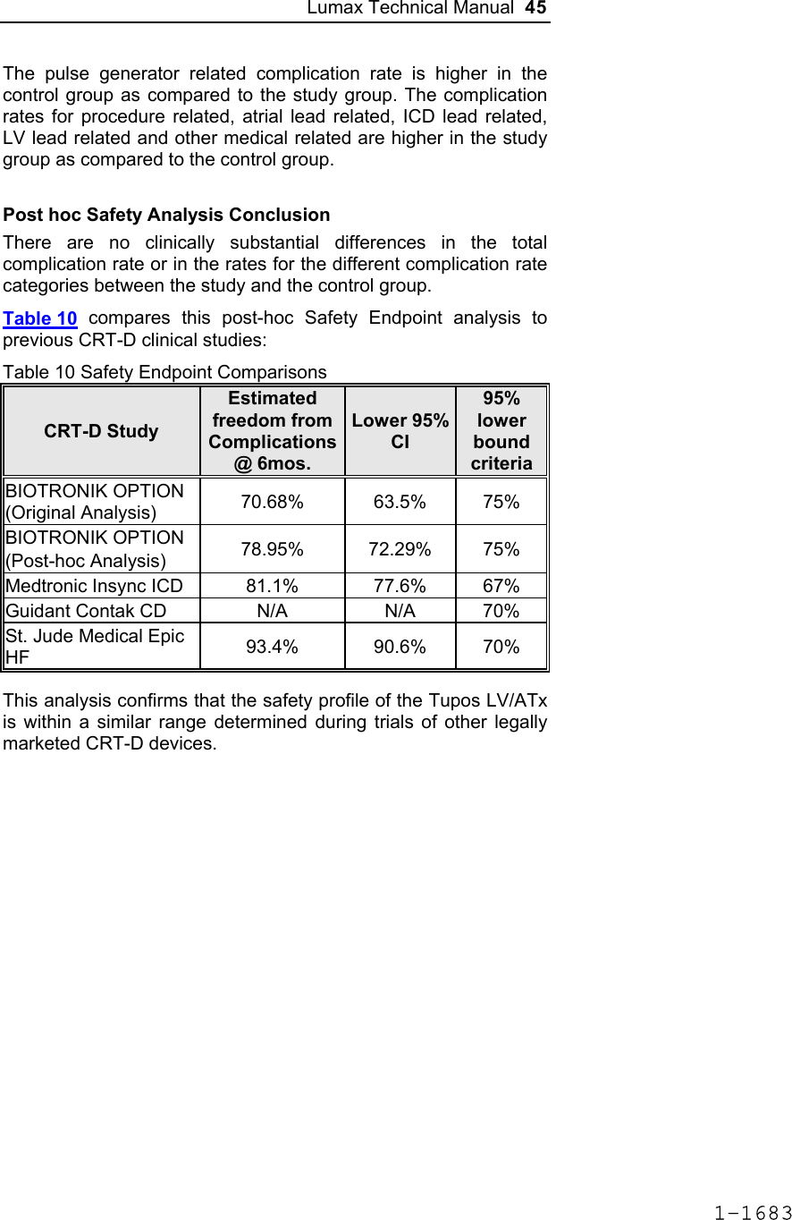
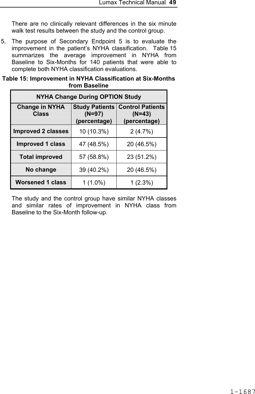
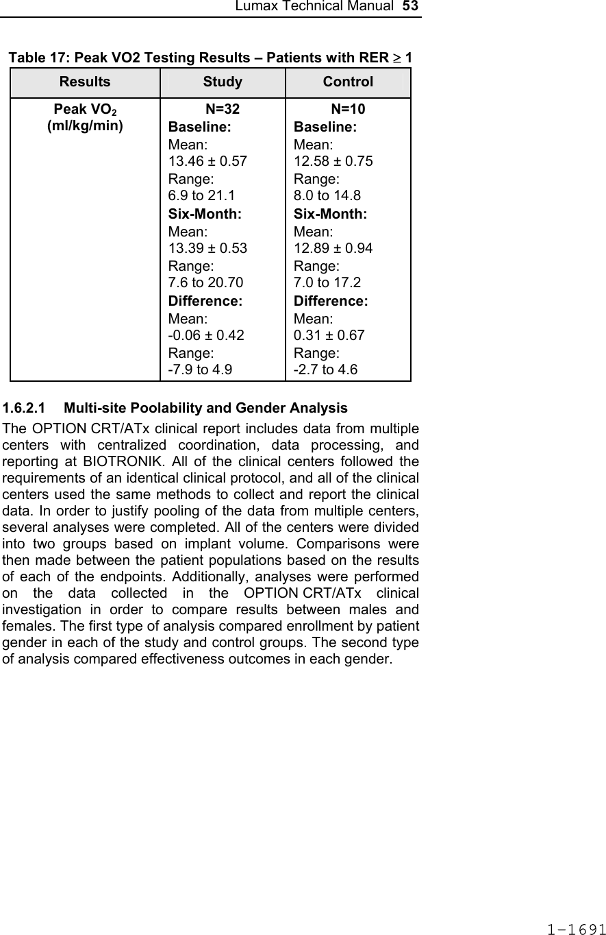
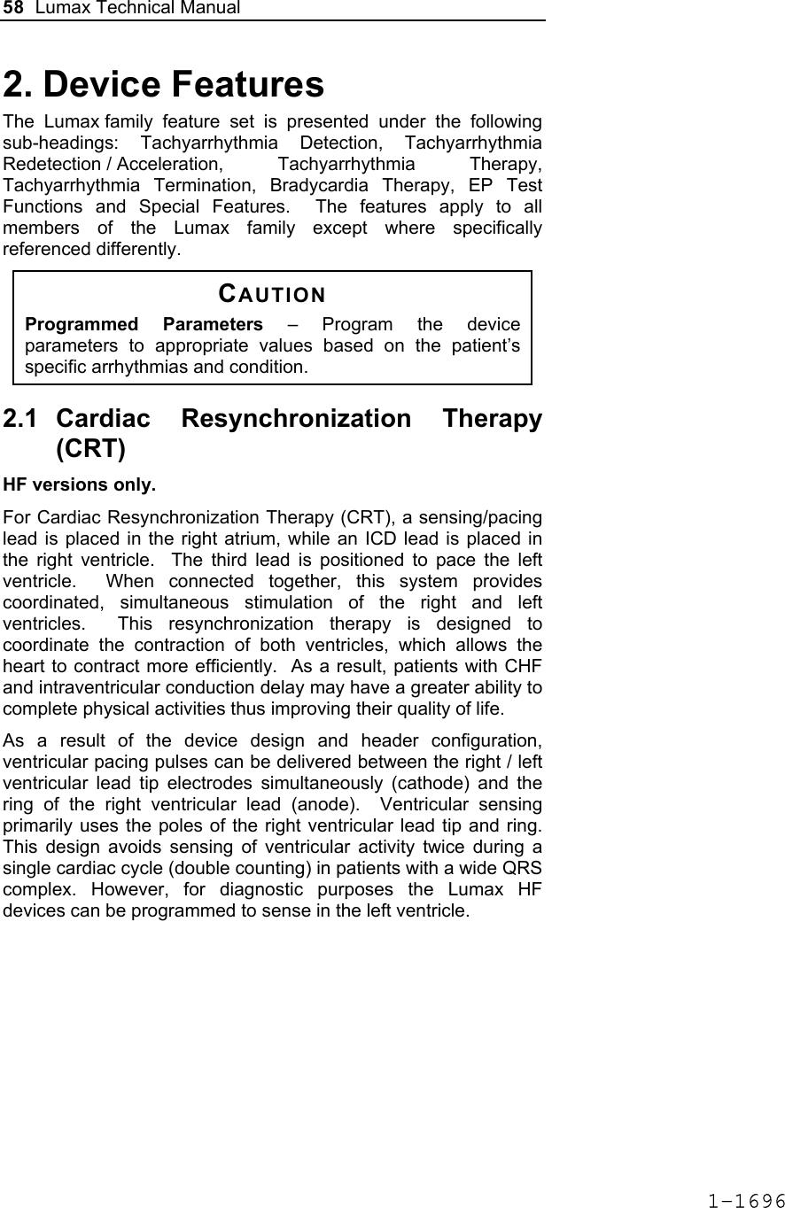
![Lumax Technical Manual 43 Table 8: Complications at 6-Month – Study and Control Study versus Control Comparison Category Study N = 133 Control N = 67 Delta 95% CI P-value Procedure Related 6 (4.51%) 1 (1.49%) 3.02% [-3.64%, 8.45%] 0.428 Atrial Lead Related 3 (2.26%) 1 (1.49%) 0.76% [-5.74%, 5.37%] 1.000 ICD Lead Related 3 (2.26%) 0 (0%) 2.26% [-3.03%, 6.53%] 0.552 LV Lead Related 26 (19.55%) 9 (13.43%) 6.12% [-5.50%, 16.45%] 0.329 Device Related 7 (5.26%) 5 (7.46%) -2.20% [-11.42%, 4.77%] 0.541 Other Medical Related 9 (6.77%) 2 (2.99%) 3.78% [-3.82%, 10.13%] 0.341 Total Procedure, Lead and Device Related 39 (29.32%) 15 (22.39%) 6.94% [-6.46%, 19.17%] 0.317 Total 46 (34.59%) 17 (25.37%) 9.21% [-4.96%, 21.99%] 0.201 Primary Safety Enpoint Analysis and Conclusions The observed procedure, lead and device related complication-free rate at 6 months was 70.68%. The 95% confidence interval for the complication-free rate was [62.16%, 78.25%]. The lower, one-sided 95% confidence bound for the complication-free rate was 63.50%. Therefore the procedure, lead and device related complication-free rate at 6 months did not meet the pre-specified acceptance criterion for this endpoint. 1-1681](https://usermanual.wiki/BIOTRONIK-SE-and-KG/LUMAXT/User-Guide-710245-Page-45.png)
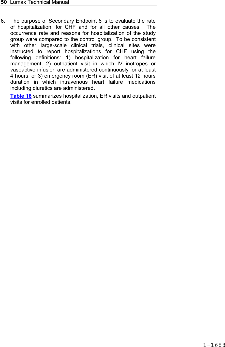
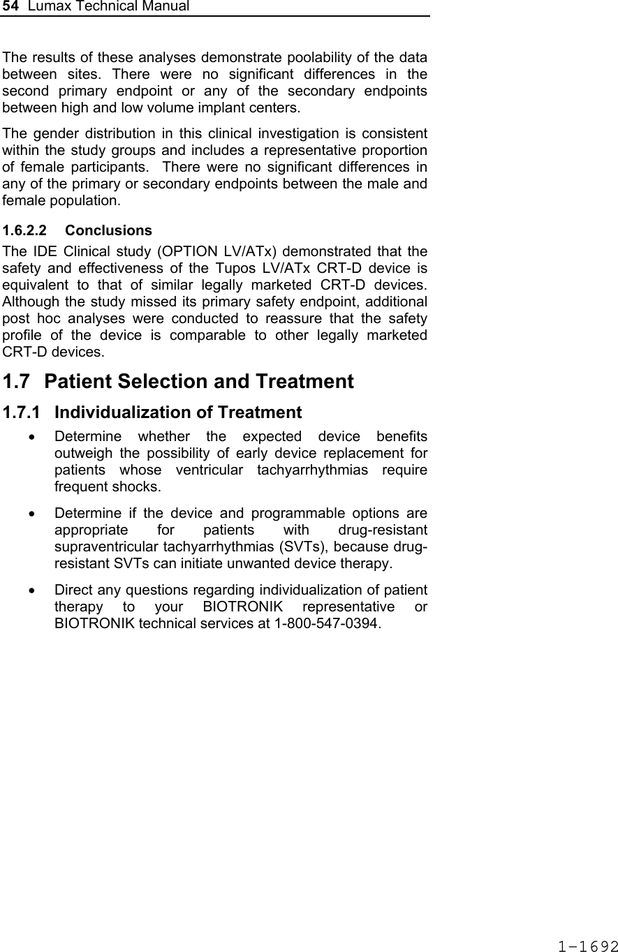
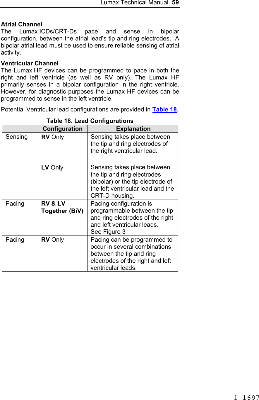
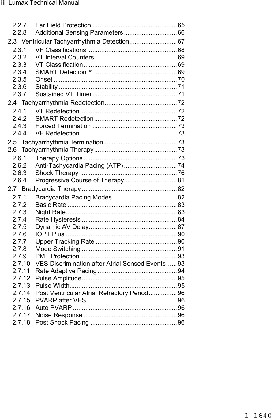
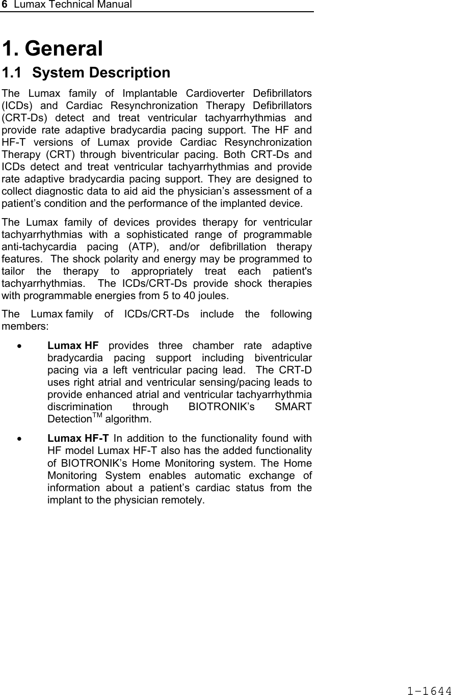
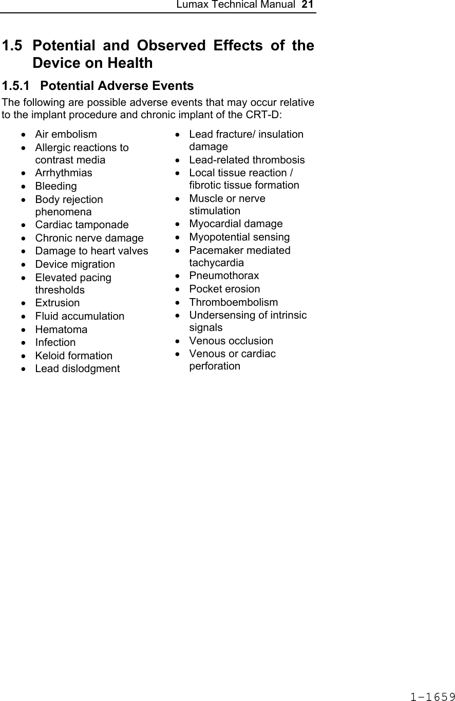
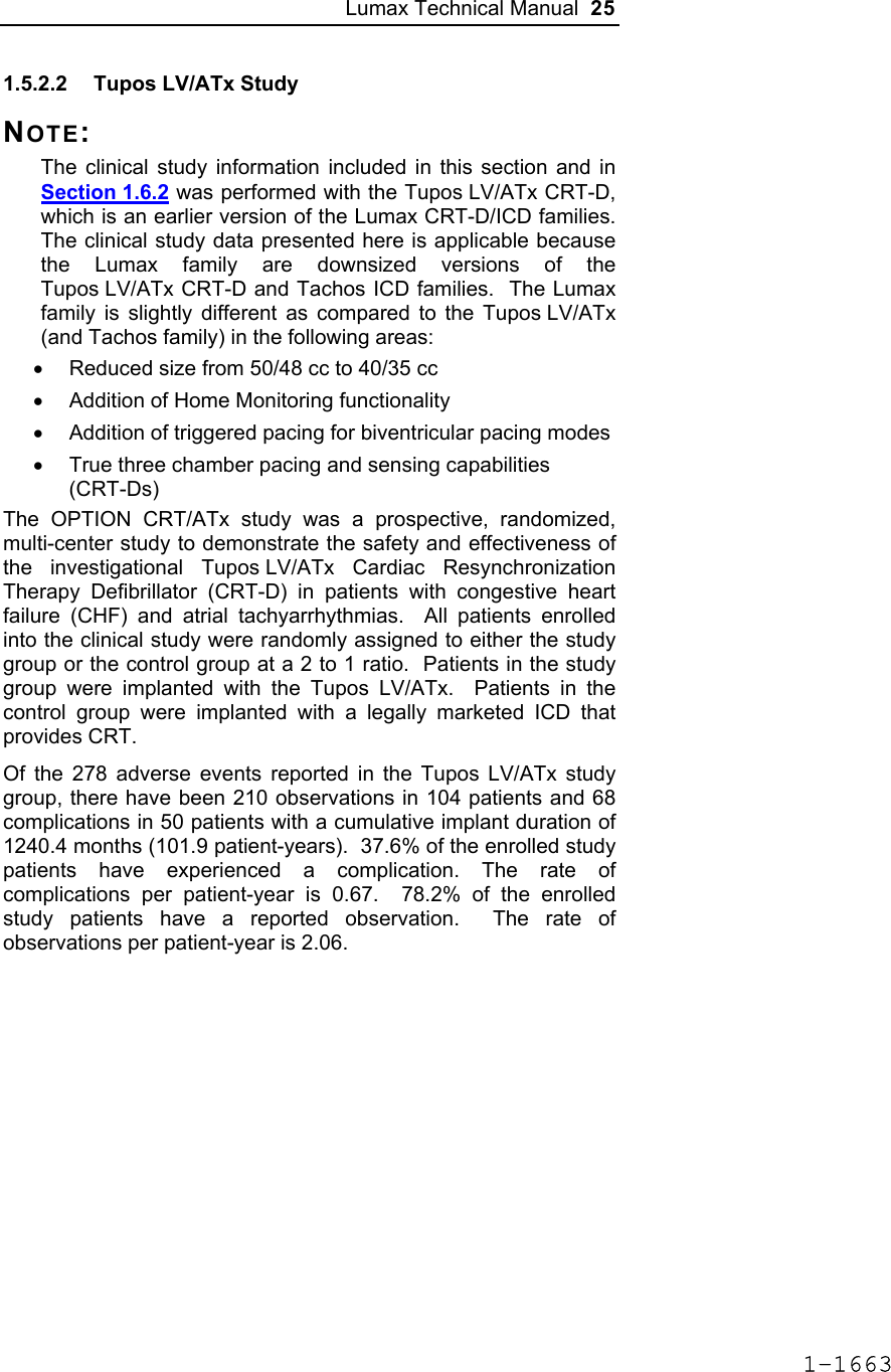
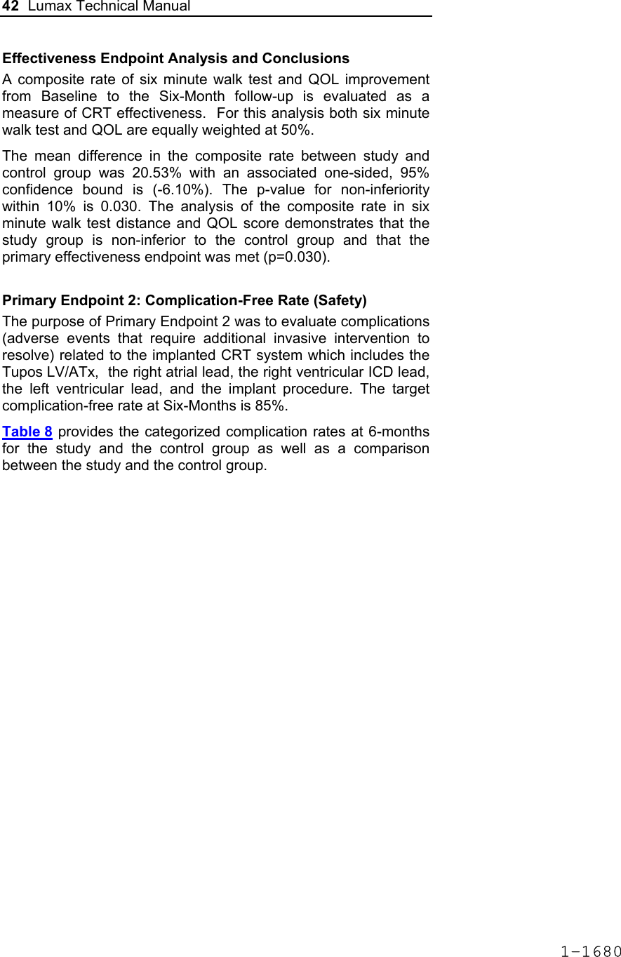
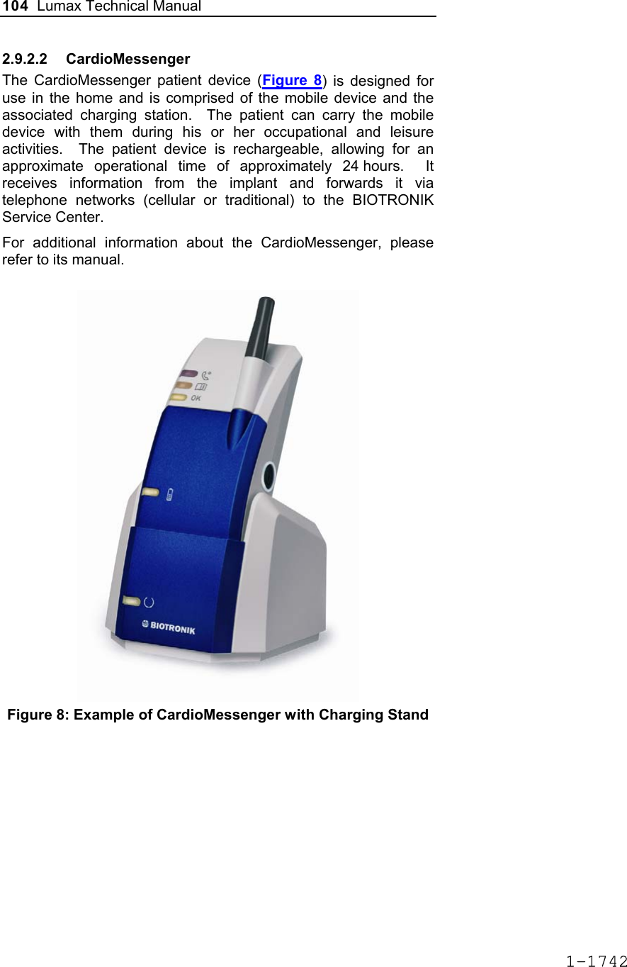
![60 Lumax Technical Manual Figure 3 Programmable BiV Pacing Configurations For CRT to be effective, ventricular pacing must occur. Therefore, AV delays must be programmed short enough to override intrinsic ventricular contractions. Additional information to further optimize AV delays can be obtained with Echocardiographs. CRT can be programmed ON or OFF via the programmer using the [Ventricular Pacing Config.] parameter. Ventricular Pacing Configuration allows either standard right ventricular [RV] pacing or Cardiac Resynchronization Therapy [BiV]. The Lumax HF CRT-D can provide triggered biventricular pacing. This is a functional expansion of the basic ventricular modes (DDD(R); DDI(R); VDI(R); VDD(R); VVI(R)) used for biventricular pacing. The “triggering function” was designed to ensure biventricular pacing therapy is delivered during rapidly conducted atrial arrhythmias, such as atrial fibrillation. This function triggers pacing delivery (Vp) in the ventricles after intrinsic sensing in the right ventricle. The trigger function is only available in the biventricular pacing configuration and includes a forced ventricular pace (Vp) after previous sensing (right ventricular sense event). Triggered pacing can be programmed to react to only normal RV sensed events or to right ventricular extrasystoles as well as normal RV sensed events. The maximum Trigger rate is limited by the programmed UTR. 1-1698](https://usermanual.wiki/BIOTRONIK-SE-and-KG/LUMAXT/User-Guide-710245-Page-62.png)

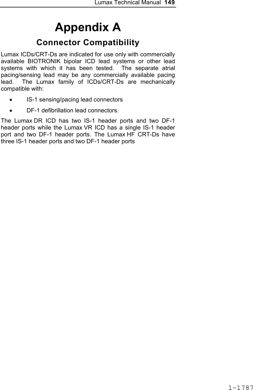
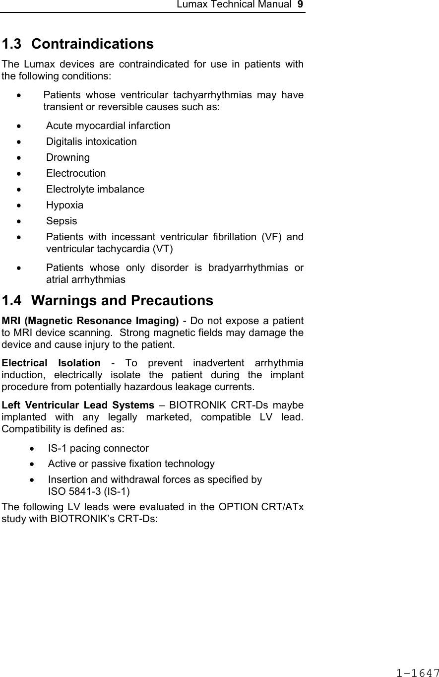
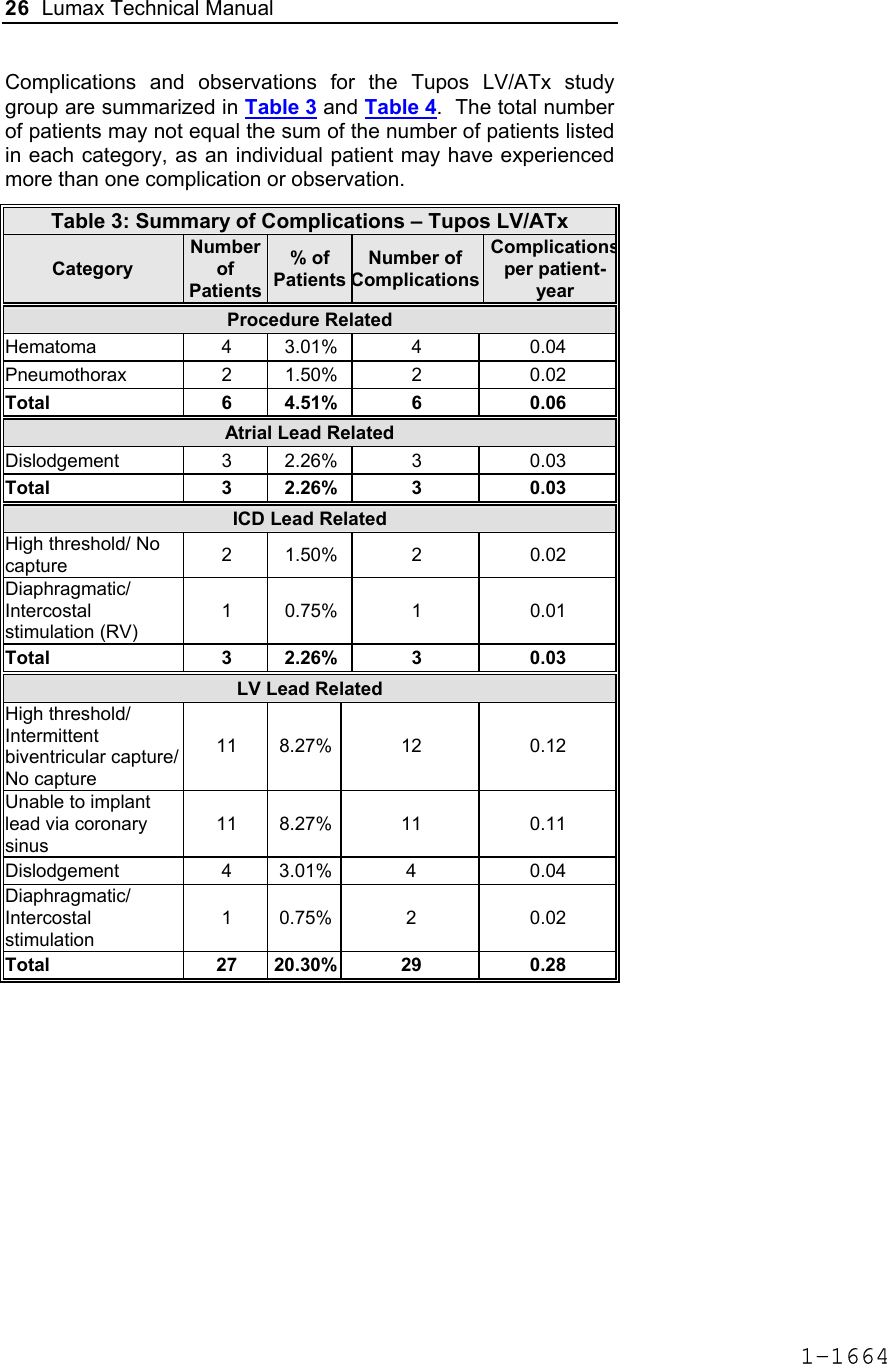
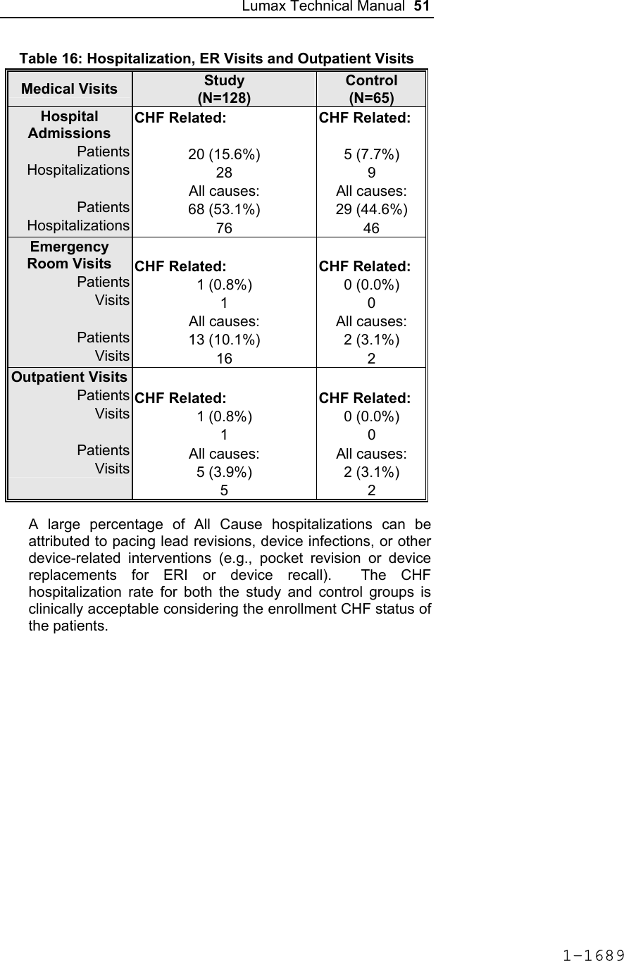
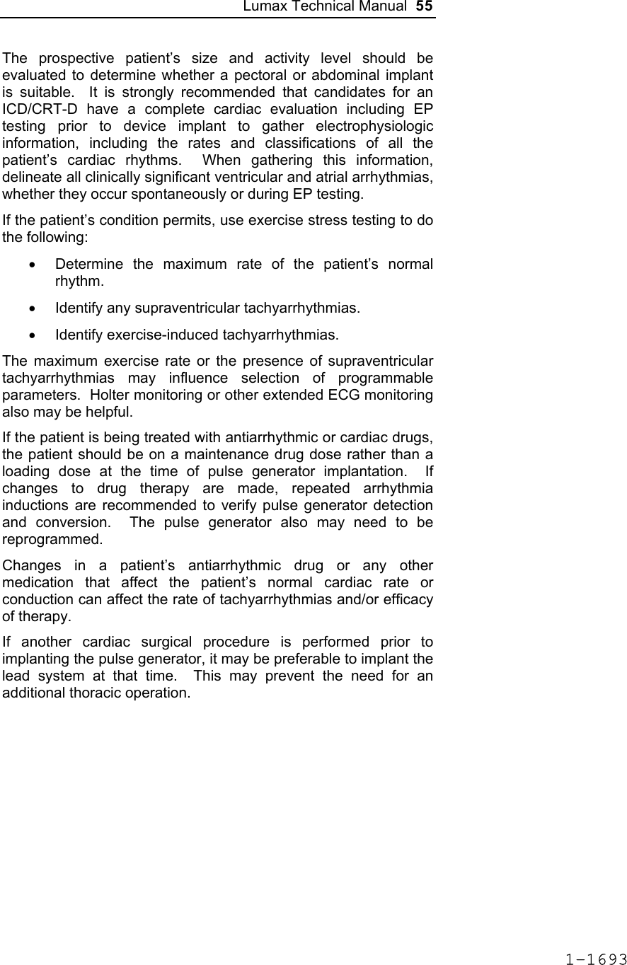
![124 Lumax Technical Manual 4.2 Lead System Evaluation The ICD/CRT-D is mechanically compatible with DF-1 defibrillation lead connectors and IS-1 sensing and pacing lead connectors. IS-1, wherever stated in this manual, refers to the international standard, whereby leads and pulse generators from different manufacturers are assured a basic fit [Reference ISO 5841-3:1992]. DF-1, wherever stated in this manual, refers to the international standard [Reference ISO 11318:1993]. Refer to the appropriate lead system technical manual. 4.3 Opening the Sterile Container The Lumax ICD/CRT-Ds are packaged in two plastic containers, one within the other. Each is individually sealed and then sterilized with ethylene oxide. Due to the double packing, the outside of the inner container is sterile and can be removed using standard aseptic technique and placed on the sterile field. ST_01 Peel off the sealing paper of the outer container as indicated by the arrow. Do not contaminate the inner tray. Take out the inner sterile tray by gripping the tab. Open the inner tray by peeling the sealing paper as indicated by the arrow. 1-1762](https://usermanual.wiki/BIOTRONIK-SE-and-KG/LUMAXT/User-Guide-710245-Page-126.png)

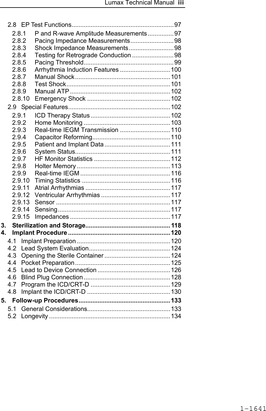
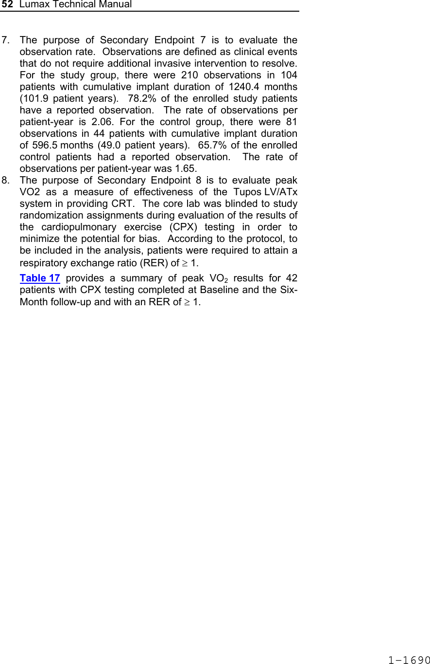
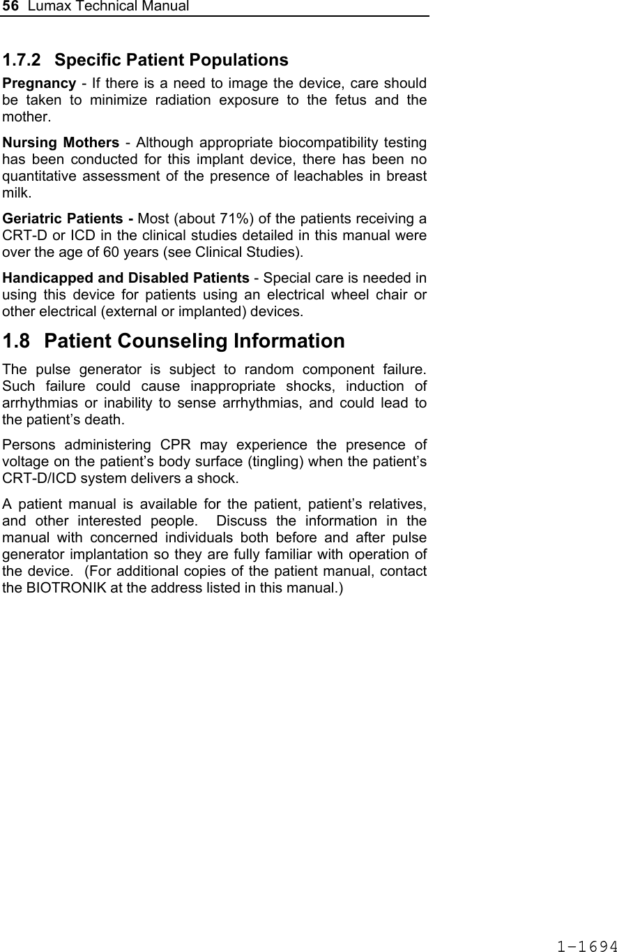
![Lumax Technical Manual 141 Parameter Range Standard Mode Mode (DR/HF) DDD, DDDR, DDI, DDIR, VDD, VDDR, VDI, VDIR, VVI, VVIR, AAI, AAIR, OFF DDD Mode (VR) VVI, VVIR, OFF VVI Basic Rate Day/Night Basic rate 30..(5)..100..(10)..160 ppm 60 ppm Night rate OFF, 30..(5)..100 ppm OFF Night beginning 00:00..(1 min)..23:59 h:m [22:00 h:m] Night ending 00:00..(1 min)..23:59 h:m [06:00 h:m] Rate Hysteresis Rate hysteresis OFF, -5..(-5)..-90 ppm OFF Repetitive OFF; 1..(1)..15 [OFF] Scan OFF; 1..(1)..15 [OFF] AV Delay AV delay Low, medium, high, fixed, individ. Low AV delay 1 40..(5)..350 ms - At rate 1 30..(10)..160 ppm 60 ppm AV delay 2 40..(5)..350 ms - At rate 2 70..(10)..160 ppm 130 ppm Sense compensation OFF; -5..(-5)..-60 ms -30 ms AV-hysteresis mode OFF, positive, negative I-Opt (only for DR devices)OFF AV hysteresis 10..(10)..150 ms [50 ms] AV repetitive (positive) OFF; 1..(1)..10 [OFF] AV repetitive (negative) OFF; 1..(1)..15..(5)..100..(10)..180 [OFF] AV scan OFF, 1..(1)..10 [OFF] I-Opt Plus (Only for DR Devices) I-Opt Plus OFF, ON OFF AV hysteresis at I-Opt 400 ms 400 ms 1-1779](https://usermanual.wiki/BIOTRONIK-SE-and-KG/LUMAXT/User-Guide-710245-Page-143.png)
![142 Lumax Technical Manual Parameter Range Standard AV repetitive at I-Opt OFF; 1..(1)..10 [5] AV scan at I-Opt OFF, 1..(1)..10 [5] AV max at I-Opt 400 ms 400ms Post-ventricular Atrial Refractory Period (PVARP) PVARP 175..(25)..600 ms 250 ms Auto PVARP OFF, ON OFF VES Classification (VES Lock-in Protection) VES differentiation after As 250..(50)..450 ms 350 ms Rate Adaptation (Acceleration Sensor) Maximum sensor rate AUTO, 90..(5)..160ppm 120ppm Sensor gain 1.0; 1.1; 1.3; 1.4; 1.6; 1.8; 2.0; 2.2; 2.6; 3.0; 3.3; 3.7; 4.0; 4.5; 5.0; 6.0; 7.0; 8.0; 8.5; 10; 11; 12; 14; 16; 18; 20; 22; 24; 28; 32; 35; 40 6.0 Auto Sensor gain OFF, ON OFF Sensor threshold Very low = 0 Low = 3 Medium = 7 High = 11 Very high = 15 Medium Rate increase 0.5; 1..(1)..6 ppm/cycle 2 ppm/cycle Rate drop 0.25..(0.25)..1.25 ppm/cycle 0.5 ppm/cycle Upper Tracking Rate (UTR) Upper tracking rate 90..(10)..160 ppm 130 ppm Upper tracking rate atrium OFF, 240 ppm 240 ppm Mode Switching Intervention rate OFF, 100..(10)..250 ppm 160 ppm Activation criterion X 3..(1)..8 5 Deactivation criterion Z 3..(1)..8 5 1-1780](https://usermanual.wiki/BIOTRONIK-SE-and-KG/LUMAXT/User-Guide-710245-Page-144.png)
![Lumax Technical Manual 143 Parameter Range Standard Mode DDI, DDIR at permanent DDD(R) VDI, VDIR at permanent VDD(R) DDI [VDI] Change in basic rate OFF, +5 ... (5) ...+30 ppm +10 ppm Post-Mode Switch Response (PMSR) Post-ModeSw rate OFF, +5 ... (5) ...+50 ppm +10 ppm Post-ModeSw duration 1..(1)..30 min 1 min PMT Protection PMT detection / termination OFF, ON ON VA criterion 250..(10)..500 ms 350 ms Detection Detection / Therapy ENABLED DISABLED ENABLED Interval Interval VT1 OFF, 270...(10)...600 ms OFF Interval VT2 OFF, 270...(10)...500 ms OFF Interval VF OFF, 200...(10)...400 ms 300 ms Detection Counter Detection counter VT1 10...(2)...60 [26] Detection counter VT2 10...(2)...40 [16] Detection counter VF – X 6...(1)...30 8 Detection counter VF – Y 8...(1)...31 12 Onset Onset in VT1/2 with SMART 20% [20%] Onset VT1 without SMART OFF; 3…(4)…32% OFF Onset VT2 without SMART OFF; 3…(4)…32% OFF Stability Stability in VT1/2 with SMART 12% [12%] 1-1781](https://usermanual.wiki/BIOTRONIK-SE-and-KG/LUMAXT/User-Guide-710245-Page-145.png)
![144 Lumax Technical Manual Parameter Range Standard Stability VT1 without SMART OFF; 8…(4)…48 ms OFF Stability VT2 without SMART OFF; 8…(4)…48 ms OFF SMART Detection SMART detection VT1 OFF, ON [ON] SMART detection VT2 OFF, ON [ON] Sustained VT (without SMART and without SMART Redetection) Sustained VT OFF, 00:30, 01:00, 02:00, 03:00, 05:00, 10:00, 15:00, 20:00, 25:00, 30:00 [mm:ss] [OFF] Forced Termination (with SMART Incl. SMART Redetection) Forced termination OFF; 1…(1)…15 min [1 min] Redetection Counter Redetection counter VT1 10...(2)...30 [20] Redetection counter VT2 10...(2)...30 [14] SMART Redetection SMART redetection (VT1 & VT2) OFF, ON [ON] Ventricular Therapy Parameters Energy 1st shock and 2nd shock VT1, VT2 (model 300) 1) OFF; 1..(1)..16..(2)..30 J 30 J Energy 1st shock and 2nd shock VF (model 300) 1..(1)..16..(2)..30 J 30 J Energy 1st shock and 2nd shock VT1, VT2 (model 340) OFF; 1..(1)..16..(2)..40 J 40 J Energy 1st shock and 2nd shock VF (model 340) 1..(1)..16..(2)..40 J 40 J 1-1782](https://usermanual.wiki/BIOTRONIK-SE-and-KG/LUMAXT/User-Guide-710245-Page-146.png)
![Lumax Technical Manual 145 Parameter Range Standard Number of shocks (VT1/VT2) 0..(1)..8 [8] Number of shocks (VF) 6..(1)..8 8 Confirmation (per zone) OFF, ON ON Shock form (per zone) Biphasic, biphasic2 Biphasic Polarity (per zone) Normal, inverse, alternating Normal ATP Parameters ATP type Burst, ramp, Burst + PES [Burst] ATP attempts OFF, 1…(1)...10 OFF S1 number 1...(1)...10 [5] Add. S1 OFF, ON [ON] R1-S1 interval 200...(10)...500 ms (absolute); 70...(5)...95 % (adaptive) [80 %] S1 (RAMP) decrement 5...(5)...40 ms [10 ms] Scan decrement OFF, 5...(5)...40 ms [OFF] S1-S2 interval 200...(10)...500 ms (absolute); 70...(5)...95 % (adaptive) [70 %] Minimal ATP interval 200...(5)...300 ms [200 ms] ATP timeout OFF, 00:15...(00:15)...05:00 mm:ss OFF ATP optimization OFF, ON OFF ATP pulse amplitude 7.5 V 7.5 V ATP pulse width 1.5 ms 1.5 ms ATP One-Shot Parameter (ATP in VF) ATP type OFF, burst, ramp, burst + PES OFF S1 number 1...(1)...10 [5] R-S1 interval 200...(10)...350 ms (absolute); 70...(5)...95 % (adaptive) [80%] 1-1783](https://usermanual.wiki/BIOTRONIK-SE-and-KG/LUMAXT/User-Guide-710245-Page-147.png)
![146 Lumax Technical Manual Parameter Range Standard S1 decrement 5...(5)...40 ms [10ms] S1-S2 interval 200...(10)...350 ms (absolute); 70...(5)...95 % (adaptive) [70%] Stability 12% 12% ATP attempts 1 [1] ATP pulse amplitude 7.5 V 7.5 V ATP pulse width 1.5 ms 1.5 ms Post-Shock Pacing Mode DDI at permanent DDD(R), DDI (R), AAI(R) VDI at permanent VDD(R), VDI(R), VVI at permanent VVI(R), OFF Basic rate 30 .. (5)..100..(10) .. 160 ppm 60 ppm Rate hysteresis OFF, -5 .. (-5) .. –65 bpm OFF AV delay 50..(10)..350 ms (fixed AV delay) 140 ms Post-shock duration OFF, 00:10 .. (00:10) .. 00:50, 01:00 .. (01:00) .. 10:00 mm:ss 00:10 mm:ss Home Monitoring Home Monitoring OFF, ON OFF Transmission time Time (hh:mm) [01:00 hh:mm] IEGM for therapy episode OFF, ON [OFF] IEGM for monitoring episode OFF, ON [OFF] Periodic IEGM OFF, 2, 3, 4, 6 months [OFF] Sustained atrial episode OFF, 0,5, 6, 12, 18 h [12 h] 1-1784](https://usermanual.wiki/BIOTRONIK-SE-and-KG/LUMAXT/User-Guide-710245-Page-148.png)