BIOTRONIK SE and KG LUMAXT50 Implantable Cardioverter defibrillator User Manual UserMan
BIOTRONIK SE & Co. KG Implantable Cardioverter defibrillator UserMan
UserMan

Lumax
Family of Implantable Cardioverter
Defibrillators and Cardiac
Resynchronization Therapy
Defibrillators
VR ICD
VR-T ICD
VR-T DX ICD
DR ICD
DR-T ICD
HF CRT-D
HF-T CRT-D
Technical Manual
X-ray Identification
Lumax Family
Implantable Cardioverter Defibrillator and Cardiac
Resynchronization Therapy Defibrillators
Inside the housing:
Belos Technical Manual iii
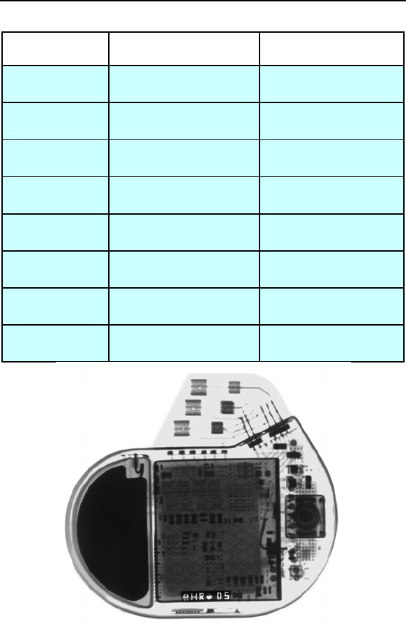
Model X-Ray Identification Year of Manufacture
Lumax 300 HR nn
Lumax 340 HR nn
Lumax 500 SH nn
Lumax 540 SH nn
Lumax 600 RH nn
Lumax 640 RH nn
Lumax 700 RH nn
Lumax 740 RH nn

CAUTION
Federal (U.S.A.) law restricts this device to sale by, or on the
order of, a physician.
2011 BIOTRONIK, Inc., all rights reserved.

Lumax Technical Manual i
Contents
1. General ..............................................................................1
1.1 System Description .......................................................1
1.2 Indications and Usage...................................................4
1.3 Contraindications...........................................................5
1.4 Warnings and Precautions ............................................5
1.4.1 Sterilization, Storage, and Handling ......................8
1.4.2 Device Implantation and Programming .................8
1.4.3 Lead Evaluation and Connection ........................10
1.4.4 Follow-up Testing ................................................12
1.4.5 Pulse Generator Explant and Disposal ...............12
1.4.6 Hospital and Medical Hazards.............................12
1.4.7 Home and Occupational Hazards .......................14
1.4.8 Cellular Phones ...................................................14
1.4.9 Electronic Article Surveillance (EAS) ..................15
1.4.10 Home Appliances ................................................15
1.4.11 Home Monitoring® ..............................................15
1.5 Potential/Observed Effects of the Device on Health ...17
1.5.1 Potential Adverse Events ....................................17
1.5.2 Observed Adverse Events...................................18
1.6 Clinical Studies ............................................................27
1.6.1 Kronos LV-T Study ..............................................28
1.6.2 Tupos LV/ATx Study............................................30
1.6.3 Lumax HF-T V-V Clinical Study...........................48
1.6.4 TRUST Clinical Study..........................................55
1.6.5 Deikos A+ ............................................................63
1.7 Patient Selection and Treatment .................................67
1.7.1 Individualization of Treatment .............................67
1.7.2 Specific Patient Populations................................68
1.8 Patient Counseling Information ...................................68
1.9 Evaluating Prospective CRT-D/ICD Patients ..............69
2. Device Features ..............................................................70
2.1 SafeSync Telemetry ....................................................70
2.2 Cardiac Resynchronization Therapy (CRT) ................73
2.3 Sensing (Automatic Sensitivity Control) ......................76
2.3.1 Right Ventricular Sensitivity Settings...................77
2.3.2 Minimum Right Ventricular Threshold .................79

ii Lumax Technical Manual
2.3.3 Atrial Sensitivity Settings .....................................79
2.3.4 Minimum Atrial Threshold....................................80
2.3.5 Left Ventricular Sensitivity Settings .....................80
2.3.6 Minimum Left Ventricular Threshold....................81
2.3.7 Far Field Protection .............................................81
2.3.8 Additional Sensing Parameters ...........................81
2.4 Automatic Threshold Measurement (ATM) .................83
2.4.1 Signal Quality Check ...........................................84
2.4.2 Threshold Measurement .....................................84
2.4.3 Loss of Capture Detection...................................84
2.4.4 ATM in Lumax HF-T Models ...............................84
2.4.5 RV & LV Capture Control ....................................85
2.5 Ventricular Tachyarrhythmia Detection........................85
2.5.1 VF Classifications ................................................86
2.5.2 VT Interval Counters............................................86
2.5.3 VT Classification..................................................86
2.5.4 SMART Detection™ ............................................87
2.5.5 Onset ...................................................................88
2.5.6 Stability ................................................................88
2.5.7 Sustained VT Timer.............................................88
2.5.8 VT Monitoring Zone .............................................89
2.5.9 Atrial Monitoring Zone .........................................89
2.6 Tachyarrhythmia Redetection......................................90
2.6.1 VT Redetection....................................................90
2.6.2 SMART Redetection............................................90
2.6.3 Forced Termination .............................................90
2.6.4 VF Redetection....................................................91
2.7 Tachyarrhythmia Termination ......................................91
2.8 Tachyarrhythmia Therapy............................................91
2.8.1 Therapy Options ..................................................91
2.8.2 Anti-Tachycardia Pacing (ATP) ...........................91
2.8.3 Shock Therapy ....................................................95
2.8.4 Progressive Course of Therapy.........................101
2.9 Bradycardia Therapy .................................................102
2.9.1 Bradycardia Pacing Modes ...............................102
2.9.2 Basic Rate .........................................................103
2.9.3 Night Rate..........................................................103
2.9.4 Rate Hysteresis .................................................104
2.9.5 Dynamic AV Delay.............................................107
2.9.6 IOPT ..................................................................110

Lumax Technical Manual iii
2.9.7 Upper Tracking Rate .........................................110
2.9.8 Mode Switching .................................................111
2.9.9 PMT Management .............................................113
2.9.10 VES Discrimination after Atrial Sensed Events.115
2.9.11 Rate-Adaptive Pacing........................................116
2.9.12 Pulse Amplitude.................................................118
2.9.13 Pulse Width .......................................................118
2.9.14 Post Ventricular Atrial Refractory Period...........118
2.9.15 PVARP after VES ..............................................118
2.9.16 Auto PVARP ......................................................119
2.9.17 Noise Response ................................................119
2.9.18 Post Shock Pacing ............................................119
2.10 EP Test Functions......................................................120
2.10.1 P and R-wave Amplitude Measurements..........120
2.10.2 Pacing Impedance Measurements....................121
2.10.3 Shock Impedance Measurements.....................121
2.10.4 Testing for Retrograde Conduction ...................122
2.10.5 Pacing Threshold...............................................122
2.10.6 Arrhythmia Induction Features ..........................123
2.10.7 Manual Shock....................................................124
2.10.8 Test Shock.........................................................124
2.10.9 Manual ATP.......................................................125
2.10.10 Emergency Shock .............................................125
2.11 Special Features........................................................125
2.11.1 ICD Therapy Status ...........................................125
2.11.2 Thoracic Impedance..........................................126
2.11.3 Home Monitoring®.............................................126
2.11.4 Real-time IEGM Transmission ..........................138
2.11.5 Capacitor Reforming .........................................139
2.11.6 Patient and Implant Data...................................140
2.11.7 System Status ...................................................140
2.11.8 HF Monitor Statistics .........................................141
2.11.9 Holter Memory ...................................................142
2.11.10 Timing Statistics ................................................144
2.11.11 Atrial Arrhythmias ..............................................145
2.11.12 Ventricular Arrhythmias .....................................145
2.11.13 Sensor ...............................................................146
2.11.14 Sensing..............................................................146
2.11.15 Impedances .......................................................146
2.11.16 Automatic Threshold..........................................146
2.11.17 Asynchronous Pacing Modes............................146

iv Lumax Technical Manual
2.11.18 Far-Field IEGM for Threshold Testing (Leadless
ECG)..................................................................147
2.11.19 Advanced AT/AF Diagnostics (Lumax 700/740 only)
...........................................................................147
2.11.20 Atrial NIPS (Lumax 700/740 & 600/640 only) ...148
3. Sterilization and Storage .............................................149
4. Implant Procedure ........................................................151
4.1 Implant Preparation ...................................................151
4.2 Lead System Evaluation............................................156
4.3 Opening the Sterile Container ...................................156
4.4 Pocket Preparation....................................................157
4.5 Lead to Device Connection .......................................158
4.6 Blind Plug Connection ...............................................161
4.7 Program the ICD/CRT-D ...........................................162
4.8 Implant the ICD/CRT-D .............................................163
5. Follow-up Procedures..................................................167
5.1 General Considerations ............................................167
5.2 Longevity ...................................................................168
5.2.1 Lumax 300/340 Devices....................................169
5.2.2 Lumax 500/540 Devices....................................171
5.2.3 Lumax 600/640 & 700/740 Devices ..................174
5.3 Explantation...............................................................176
6. Technical Specifications..............................................179
Appendix A ..........................................................................198
Appendix B – Known Anomalies.......................................200
Lumax Technical Manual v
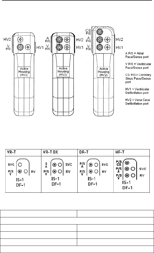
Figure 1. Lumax 300/340 ICDs and CRT-D
VR(-T) DR(-T)/VR-T DX HF(-T)
Figure 2. Lumax 500/540, 600/640 & 700/740 ICDs and CRT-D
Table 1. Lumax Specifications
Battery Voltage 3.2 Volts
Maximum Shock Energy
300/500/600/700 Models 30 Joules programmed
340/540/640/740 Models 40 Joules programmed
Defibrillation Lead Ports Two DF1 (3.2 mm)
Pacing Lead Ports


Lumax Technical Manual 1
1. General
1.1 System Description
The Lumax family of Implantable Cardioverter Defibrillators
(ICDs) and Cardiac Resynchronization Therapy Defibrillators
(CRT-Ds) detect and treat ventricular tachyarrhythmias and
provide rate adaptive bradycardia pacing support. The HF and
HF-T versions of Lumax provide Cardiac Resynchronization
Therapy (CRT) through biventricular pacing. Both CRT-Ds and
ICDs detect and treat ventricular tachyarrhythmias and provide
rate adaptive bradycardia pacing support. They are designed to
collect diagnostic data to aid the physician’s assessment of a
patient’s condition and the performance of the implanted device.
The Lumax family of devices provides therapy for ventricular
tachyarrhythmias with a sophisticated range of programmable
anti-tachycardia pacing (ATP), and/or defibrillation therapy
features. The shock polarity and energy may be programmed to
tailor the therapy to appropriately treat each patient's
tachyarrhythmias. The ICDs/CRT-Ds provide shock therapies
with programmable energies from 5 to 40 joules.
The Lumax family of ICDs/CRT-Ds includes the following
members:
Lumax HF - provides three chamber rate-adaptive
bradycardia pacing support including biventricular pacing
via a left ventricular pacing lead. The CRT-D uses right
atrial and ventricular sensing/pacing leads to provide
enhanced atrial and ventricular tachyarrhythmia
discrimination through BIOTRONIK’s SMART Detection™
algorithm.
Lumax HF-T - In addition, to the functionality found with
HF model, Lumax HF-T also has BIOTRONIK’s Home
Monitoring system. The Home Monitoring System
enables automatic exchange of information about a
patient’s cardiac status from the implant to the physician
remotely.
Lumax DR - provides dual chamber rate adaptive
bradycardia pacing support. The ICD uses atrial and
ventricular sensing/pacing leads to provide enhanced
atrial and ventricular tachyarrhythmia discrimination
through BIOTRONIK’s SMART DetectionTM algorithm.

2 Lumax Technical Manual
Lumax DR-T - In addition, to the functionality found with
the DR model, it also has BIOTRONIK’s Home
Monitoring® system. The Home Monitoring System
enables automatic exchange of information about a
patient’s cardiac status from the implant to the physician
remotely.
Lumax VR - provides single chamber rate adaptive
bradycardia pacing support as well as tachyarrhythmia
detection and therapy.
Lumax VR-T - In addition, to the functionality found with
standard VR model, it also has BIOTRONIK’s Home
Monitoring system. The Home Monitoring System
enables automatic exchange of information about a
patient’s cardiac status from the implant to the physician
remotely.
Lumax VR-T DX – provides ventricular rate adaptive
bradycardia pacing support that can include atrial
tracking with a single pass ICD lead and also has
BIOTRONIK’s Home Monitoring system.
The 300/500/600/700 and 340/540/640/740 designation for each
of the above-described models denote the maximum
programmable shock energy of 30 joules and 40 joules,
respectively.
The Lumax 500/540, 600/640 and 700/740 models feature a third
programmable shock path for delivery of
defibrillation/cardioversion shocks. The shock path is
programmable between the different shock coils (SVC/RV) and/or
the device housing. Section 2.8.3.6 provides further details on
the available shock configurations. The Lumax 600/640 and
700/740 models also feature an additional left ventricular (LV)
pacing polarity for HF-T devices from LV-tip to housing (unipolar).
Additionally, the Lumax 500/540 models feature Automatic
Threshold Measurement (ATM) of ventricular pacing thresholds.
This feature is separately programmable for the right (RV) and left
(LV) ventricle. Section 2.4 provides further details.

Lumax Technical Manual 3
The Lumax 700/740 and 600/640 models feature ATM with
automatic adjustment of pacing amplitudes (RV & LV Capture
Control). This feature functions the same as ATM for threshold
search and is also separately programmable for the right (RV)
and left (LV) ventricle. In addition, it automatically adjusts the
permanent pacing amplitude with a programmed safety margin.
Section 2.4.5 provides a detailed description of this feature.
The Lumax 600/640 and 700/740 also provides wandless
telemetry to ease implantation and follow-up procedures. In
addition, these devices include Thoracic Impedance monitoring
and Atrial NIPS that can be used for an EP study to induce an
arrhythmia or to burst pace a patient out of a stable
tachyarrhythmia.
Lumax 700/740 and 600/640 will present with automatic Far-Field
IEGM to provide a means to generate the surface ECG-like signal
without the need for attaching the surface electrodes to the
patients.
The Lumax HF (-T) models have three IS-1 pacing/sensing
header ports and two DF-1 defibrillation/cardioversion ports. The
Lumax DR (-T) models have two IS-1 pacing/sensing header
ports. The Lumax VR (-T) models have one IS-1 pacing/sensing
header ports. IS-1 refers to the international standard whereby
leads and generators from different manufacturers are assured a
basic fit [Reference ISO 5841-3:1992]. DF-1 refers to the
international standard for defibrillation lead connectors
[Reference ISO 11318:1993].
External devices that interact with and test the implantable
devices are also part of the ICD/CRT-D System. These external
devices include the Programming and Tachyarrhythmia
Monitoring System and the Implant Module System Analyzer or
Pacing System Analyzer for acute lead testing. The ICS 3000 or
Renamic programmer are used to interrogate and program the
ICD/CRT-Ds.
The Lumax 600/640 and 700/740 models also feature SafeSync
Telemetry (RF-Telemetry) via the Renamic programmer or the
ICS 3000 programmer in combination with the SafeSync Module
(an external communication module).

4 Lumax Technical Manual
BIOTRONIK conducted the TRUST study to evaluate the safety
and effectiveness of Home Monitoring, which is available in most
models of this device. Refer to Section 1.6.4 for details regarding
the study design and results. With the TRUST study,
BIOTRONIK was able to show the following with regards to Home
Monitoring:
BIOTRONIK Home Monitoring information may be used as a
replacement for device interrogation during in-office follow-up
visits.
A strategy of care using BIOTRONIK Home Monitoring with
office visits when needed has been shown to extend the time
between routine, scheduled in-office follow-ups of
BIOTRONIK implantable devices in many patients. Home
Monitoring data is helpful in determining the need for
additional in-office follow-up.
BIOTRONIK Home Monitoring-patients—who are followed
remotely with office visits when needed—have been shown to
have similar numbers of strokes, invasive procedures and
deaths as patients followed with conventional in-office
follow-ups.
BIOTRONIK Home Monitoring provides early detection of
arrhythmias.
BIOTRONIK Home Monitoring provides early detection of
silent, asymptomatic arrhythmias.
Automatic early detection of arrhythmias and device system
anomalies by BIOTRONIK Home Monitoring allows for earlier
intervention than conventional in-office follow-ups.
BIOTRONIK Home Monitoring allows for improved access to
patient device data compared to conventional in-office
follow-ups since device interrogation is automatically
scheduled at regular intervals.
1.2 Indications and Usage
The Lumax CRT-Ds are indicated for use in patients with all of the
following conditions:
Indicated for ICD therapy
Receiving optimized and stable Congestive Heart Failure
(CHF) drug therapy
Symptomatic CHF (NYHA Class III/IV and LVEF 35%);
and

Lumax Technical Manual 5
Intraventricular conduction delay (QRS duration 130 ms)
The Lumax Implantable Cardioverter Defibrillators (ICDs) and
Cardiac Resynchronization Therapy Defibrillators (CRT-Ds) are
intended to provide ventricular anti-tachycardia pacing and
ventricular defibrillation, for automated treatment of life-
threatening ventricular arrhythmias.
1.3 Contraindications
The Lumax devices are contraindicated for use in patients with
the following conditions:
Patients whose ventricular tachyarrhythmias may have
transient or reversible causes such as:
Acute myocardial infarction
Digitalis intoxication
Drowning
Electrocution
Electrolyte imbalance
Hypoxia
Sepsis
Patients with incessant ventricular fibrillation (VF) and
ventricular tachycardia (VT)
Patients whose only disorder is brady arrhythmias or
atrial arrhythmias
1.4 Warnings and Precautions
MRI (Magnetic Resonance Imaging) - Do not expose a patient
to MRI device scanning. Strong magnetic fields may damage the
device and cause injury to the patient.
Electrical Isolation - To prevent inadvertent arrhythmia
induction, electrically isolate the patient during the implant
procedure from potentially hazardous leakage currents.
Left Ventricular Lead Systems – BIOTRONIK CRT-Ds may be
implanted with any legally marketed, compatible LV lead.
Compatibility is defined as:
IS-1 pacing connector
Active or passive fixation technology
Insertion and withdrawal forces as specified by
ISO 5841-3 (IS-1)

6 Lumax Technical Manual
The following LV leads were evaluated in the OPTION CRT/ATx
study with BIOTRONIK’s CRT-Ds:
Guidant-EASYTRAK® IS-1 Lead
Guidant-EASYTRAK LV-1 Lead
Guidant-EASYTRAK 2 Lead
Guidant-EASYTRAK 3 Lead
Medtronic-Attain® OTW Lead
St. Jude-AesculaTM Lead
St. Jude-QuickSite® Lead
Biomec-MyoporeTM Epicardial Lead
Medtronic-Epicardial 5071 Lead
Medtronic-CapSure® EPI Lead
BIOTRONIK-ELC 54-UP Lead
The following LV leads were bench tested for compatibility with
BIOTRONIK’s CRT-Ds:
Guidant EASYTRAK 4512 (unipolar) Lead
Guidant EASYTRAK 4513 (bipolar) Lead
Guidant EASYTRAK 3 4525 (bipolar) Lead
Medtronic Attain OTW 4193 (unipolar) Lead
Medtronic Attain OTW 4194 (bipolar) Lead
Medtronic Attain LV 2187 (unipolar) Lead
St. Jude Medical QuickSite 1056K (unipolar) Lead
ELA SITUS® OTW (unipolar) Lead
BIOTRONIK Corox OTW 75-UP Steroid #346542
(unipolar) Lead
BIOTRONIK Corox+ LV-H 75-BP #341885 (bipolar) Lead
ICD Lead Systems – BIOTRONIK ICDs/CRT-Ds maybe
implanted with any legally marketed, compatible ICD lead.
Compatibility is defined as:
IS-1 pacing and sensing connector(s)
DF-1 shock coil connector(s)
Integrated or dedicated bipolar pacing and sensing
configuration
Active or passive fixation technology
Single or dual defibrillation shock coil (s)
High energy shock accommodation of at least 30 joules

Lumax Technical Manual 7
Insertion and withdrawal forces as specified by
ISO 5841-3 (IS-1) and ISO 11318:1993 (E) DF-1
The following leads were evaluated in a retrospective study with
BIOTRONIK’s ICDs/CRT-Ds:
Medtronic SprintTM Lead 6932
Medtronic Sprint Lead 6943
Medtronic Sprint QuattroTM Lead 6944
Medtronic TransveneTM RV Lead 6936
St. Jude (Ventritex) TVLTM- ADX Lead 1559
St. Jude SPL® SP02 Lead
Guidant ENDOTAK® DSP Lead
Guidant ENDOTAK Endurance EZ Lead, ENDOTAK
Reliance Lead
Guidant (Intermedics) Lead 497-24.
The following leads were bench tested for compatibility with
BIOTRONIK’s ICDs/CRT-Ds:
Guidant ENDOTAK Endurance Lead “CPI 0125”
Guidant ENDOTAK Reliance Lead 0148
Medtronic Sprint Lead 6932
Medtronic Sprint Lead 6942
Medtronic Sprint Lead 6943
Medtronic Sprint Lead6945
Medtronic Sprint Quattro Lead 6944
St. Jude Riata® Lead 1571/65
St. Jude SPL SPO1 Lead.
Resuscitation Availability - Do not perform induction testing
unless an alternate source of patient defibrillation such as an
external defibrillator is readily available. In order to implant the
ICD/CRT-D system, it is necessary to induce and convert the
patient’s ventricular tachyarrhythmias.
Unwanted Shocks – Always program ICD Therapy to OFF prior
to handling the device to prevent the delivery of serious shocks to
the patient or the person handling the device during the implant
procedure.
Rate-Adaptive Pacing – Use rate-adaptive pacing with care in
patients unable to tolerate increased pacing rates.

8 Lumax Technical Manual
1.4.1 Sterilization, Storage, and Handling
Device Packaging - Do not use the device if the device’s
packaging is wet, punctured, opened or damaged because the
integrity of the sterile packaging may be compromised. Return the
device to BIOTRONIK.
Re-sterilization - Do not re-sterilize and re-implant explanted
devices.
Storage (temperature) - Store the device between 5° to 45°C
(41° - 113° F) because temperatures outside this range could
damage the device.
Storage (magnets) - To avoid damage to the device, store the
device in a clean area, away from magnets, kits containing
magnets, and sources of electromagnetic interference (EMI).
Temperature Stabilization - Allow the device to reach room
temperature before programming or implanting the device
because temperature extremes may affect initial device function.
Use Before Date - Do not implant the device after the USE
BEFORE DATE because the device may have reduced longevity.
1.4.2 Device Implantation and Programming
Blind Plug - A blind plug must be inserted and firmly connected
into any unused header port to prevent chronic fluid influx and
possible shunting of high energy therapy.
Capacitor Reformation - Infrequent charging of the high voltage
capacitors may extend the charge times of the ICD/CRT-D. The
capacitors are reformed automatically at least every 90 days. For
further information, please refer to Section 2.11.5, Capacitor
Reforming.
Connector Compatibility – ICD/CRT-D and lead system
compatibility should be confirmed prior to the implant procedure.
Consult your BIOTRONIK representative regarding lead/pulse
generator compatibility prior to the implantation of an ICD/CRT-D
system. For further information, please refer to Appendix A.

Lumax Technical Manual 9
ERI (Elective Replacement Indicator) - Upon reaching ERI, the
battery has sufficient energy remaining to continue monitoring for
at least three months and to deliver a minimum of six maximum
energy shocks. After this period (EOS), all tachyarrhythmia
detection and therapy is disabled. Bradycardia functions are still
active at programmed values until the battery voltage drops below
1.75 volts.
Magnets - Positioning of a magnet or the programming wand
over the ICD/CRT-D will suspend tachycardia detection and
treatment. The minimum magnet strength required to suspend
tachycardia treatment is 1.8 mT. When the magnet strength
decreases to less than 1 mT, the reed contact is reopened.
Programmed Parameters – Program the device parameters to
appropriate values based on the patient’s specific arrhythmias
and condition.
Programmers - Use only BIOTRONIK ICS 3000 or Renamic
programmers to communicate with the device.
Sealing System - Failure to properly insert the torque wrench
into the perforation at an angle perpendicular to the connector
receptacle may result in damage to the sealing system and its
self-sealing properties.
Defibrillation Threshold - Be aware that changes in the patient’s
condition, drug regimen, and other factors may change the
defibrillation threshold (DFT) which may result in non-conversion
of the arrhythmia post-operatively. Successful conversion of
ventricular fibrillation or ventricular tachycardia during arrhythmia
conversion testing is no assurance that conversion will occur
post-operatively.
Manual Shocks – User-commanded shocks may be withheld if
the ICD/CRT-D is already busy processing a manual command or
the Battery Status is low.
Charge Time - When preparing a high energy shock the charge
circuit stops charging the capacitors after 20 seconds, and
delivers the stored energy as shock therapy. After the device
reaches ERI the stored energy may be less than the maximum
programmable energy for each shock.

10 Lumax Technical Manual
Programming Wand Separation Distance – The wand (with
magnet) must not be placed closer than 2 cm to the device
(implanted or out of the box). Programming wand (with magnet)
distance closer than 2 cm may damage the device.
Shipment Mode – The shipment mode is a factory set mode that
controls the charge current of automatic capacitor reformations.
This mode controls the charge current to avoid temporary low
battery readings. The shipment mode is automatically deactivated
as soon as electrophysiological tests (e.g., Impedance
measurement) have been performed. To ensure delivery of
programmed shock energy, make sure shipment mode is
disabled prior to completion of implant procedure.
Shock Therapy Confirmation – Programming CONFIRMATION
to OFF may increase the incidence of the ICD/CRT-D delivering
inappropriate shocks.
Shock Impedance - If the shock impedance is less than twenty-
five ohms (25 Ω), reposition the lead system to allow a greater
distance between the electrodes. Never implant the device with a
lead system that has measured shock impedance of less than
twenty-five ohms (25 Ω). Damage to the device may result.
Negative AV Hysteresis – This feature insures ventricular
pacing, a technique which has been used in patients with
hypertrophic obstructive cardiomyopathy (HOCM) with normal AV
conduction in order to replace intrinsic ventricular activation. No
clinical study was conducted to evaluate this feature, and there is
conflicting evidence regarding the potential benefit of ventricular
pacing therapy for HOCM patients. In addition, there is evidence
with other patient groups to suggest that inhibiting the intrinsic
ventricular activation sequence by right ventricular pacing may
impair hemodynamic function and/or survival.
1.4.3 Lead Evaluation and Connection
Capping Leads - If a lead is abandoned rather than removed, it
must be capped to ensure that it is not a pathway for currents to
or from the heart.
Gripping Leads - Do not grip the lead with surgical instruments
or use excessive force or surgical instruments to insert a stylet
into a lead.

Lumax Technical Manual 11
Kinking Leads - Do not kink leads. This may cause additional
stress on the leads that can result in damage to the lead.
Liquid Immersion - Do not immerse leads in mineral oil, silicone
oil, or any other liquid.
Short Circuit - Ensure that none of the lead electrodes are in
contact (a short circuit) during delivery of shock therapy as this
may cause current to bypass the heart or cause damage to the
ICD/CRT-D system.
Far-Field Sensing of signals from the atrium in the ventricular
channel or ventricular signals in the atrial channel should be
avoided by appropriate lead placement, programming of
pacing/sensing parameters, and maximum sensitivity settings. If it
is necessary to modify the Far Field Blanking parameter, the
parameter should be lengthened only long enough to eliminate
far-field sensing as evidenced on the IEGMs. Extending the
parameter unnecessarily may cause under sensing of actual atrial
or ventricular events.
Suturing Leads - Do not suture directly over the lead body as
this may cause structural damage. Use the appropriate suture
sleeve to immobilize the lead and protect it against damage from
ligatures.
Tricuspid Valve Bioprosthesis - Use ventricular transvenous
leads with caution in patients with a tricuspid valvular
bioprosthesis.
Setscrew Adjustment – Back-off the setscrew(s) prior to
insertion of lead connector(s) as failure to do so may result in
damage to the lead(s), and/or difficulty connecting lead(s).
Cross Threading Setscrew(s) – To prevent cross threading the
setscrew(s), do not back the setscrew(s) completely out of the
threaded hole. Leave the torque wrench in the slot of the
setscrew(s) while the lead is inserted.
Tightening Setscrew(s) – Do not over tighten the setscrew(s).
Use only the BIOTRONIK supplied torque wrench.
Sealing System – Be sure to properly insert the torque wrench
into the perforation perpendicular to the connector receptacle.
Failure to do so may result in damage to the plug and its self-
sealing properties.

12 Lumax Technical Manual
1.4.4 Follow-up Testing
Defibrillation Threshold - Be aware that changes in the patient’s
condition, drug regimen, and other factors may change the
defibrillation threshold (DFT), which may result in non-conversion
of the arrhythmia post-operatively. Successful conversion of
ventricular fibrillation or ventricular tachycardia during arrhythmia
conversion testing is no assurance that conversion will occur
post-operatively.
Resuscitation Availability - Ensure that an external defibrillator
and medical personnel skilled in cardiopulmonary resuscitation
(CPR) are present during post-implant device testing should the
patient require external rescue.
Safe Program – Within the EP Test screen, pressing the “Safe
Program” key on the programmer head immediately sends the
safe program to the ICD/CRT-D.
1.4.5 Pulse Generator Explant and Disposal
Device Incineration – Never incinerate the ICD/CRT-D due to
the potential for explosion. The ICD/CRT-D must be explanted
prior to cremation.
Explanted Devices – Return all explanted devices to
BIOTRONIK.
Unwanted Shocks – Always program ICD Therapy to OFF prior
to handling the device to prevent the delivery of serious shocks to
the patient or the person handling the device during the
procedure.
1.4.6 Hospital and Medical Hazards
Electromagnetic interference (EMI) signals present in hospital
and medical environments may affect the function of any
ICD/CRT-D or pacemaker. The ICD/CRT-D is designed to
selectively filter out EMI noise. However, due to the variety of EMI
signals, absolute protection from EMI is not possible with this or
any other ICD/CRT-D.
The ICD/CRT-D system should have detection and therapy
disabled (OFF) prior to performing any of the following medical
procedures. In addition, the ICD/CRT-D should be checked after
the procedures to assure proper programming:

Lumax Technical Manual 13
Diathermy - Diathermy therapy is not recommended for
ICD/CRT-D patients due to possible heating effects of the pulse
generator and at the implant site. If diathermy therapy must be
used, it should not be applied in the immediate vicinity of the
pulse generator or lead system.
Electrocautery - Electrosurgical cautery could induce ventricular
arrhythmias and/or fibrillation, or may cause device malfunction or
damage. If use of electrocautery is necessary, the current path
and ground plate should be kept as far away from the pulse
generator and leads as possible (at least 6 inches (15 cm)).
External Defibrillation - The device is protected against energy
normally encountered from external defibrillation. However, any
implanted device may be damaged by external defibrillation
procedures. In addition, external defibrillation may also result in
permanent myocardial damage at the electrode-tissue interface as
well as temporary or permanent elevated pacing thresholds. When
possible, observe the following precautions:
Position the adhesive electrodes or defibrillation paddles
of the external defibrillator anterior-posterior or along a
line perpendicular to the axis formed by the implanted
device and the heart.
Set the energy to a level not higher than is required to
achieve defibrillation.
Place the paddles as far as possible away from the
implanted device and lead system.
After delivery of an external defibrillation shock,
interrogate the ICD/CRT-D to confirm device status and
proper function.
Lithotripsy - Lithotripsy may damage the ICD/CRT-D. If
lithotripsy must be used, avoid focusing near the ICD/CRT-D
implant site.
MRI (Magnetic Resonance Imaging) - Do not expose a patient
to MRI device scanning. Strong magnetic fields may damage the
device and cause injury to the patient.
Radiation - High radiation sources such as cobalt 60 or gamma
radiation should not be directed at the pulse generator. If a patient
requires radiation therapy in the vicinity of the pulse generator,
place lead shielding over the device to prevent radiation damage
and confirm its function after treatment.

14 Lumax Technical Manual
Radio Frequency Ablation - Prior to performing an ablation
procedure, deactivate the ICD/CRT-D during the procedure.
Avoid applying ablation energy near the implanted lead system
whenever possible.
1.4.7 Home and Occupational Hazards
Patients should be directed to avoid devices that generate strong
electromagnetic interference (EMI) or magnetic fields. EMI could
cause device malfunction or damage resulting in non-detection or
delivery of unneeded therapy. Moving away from the source or
turning it off will usually allow the ICD/CRT-D to return to its
normal mode of operation.
The following equipment (and similar devices) may affect normal
ICD/CRT-D operation: electric arc or resistance welders, electric
melting furnaces, radio/television and radar transmitters,
power-generating facilities, high-voltage transmission lines, and
electrical ignition systems (of gasoline-powered devices) if
protective hoods, shrouds, etc., are removed.
1.4.8 Cellular Phones
Testing has indicated there may be a potential interaction
between cellular phones and BIOTRONIK ICD/CRT-D systems.
Potential effects may be due to either the cellular phone signal or
the magnet within the telephone and may include inhibition of
therapy when the telephone is within 6 inches (15 centimeters) of
the ICD/CRT-D, when the ICD/CRT-D is programmed to standard
sensitivity.
Patients having an implanted BIOTRONIK ICD/CRT-D who
operate a cellular telephone should:
Maintain a minimum separation of 6 inches
(15 centimeters) between a hand-held personal cellular
telephone and the implanted device.
Set the telephone to the lowest available power setting, if
possible.

Lumax Technical Manual 15
Patients should hold the phone to the ear opposite the
side of the implanted device. Patients should not carry
the telephone in a breast pocket or on a belt over or
within 6 inches (15 centimeters) of the implanted device
as some telephones emit signals when they are turned
ON, but not in use (i.e., in the listen or stand-by mode).
Store the telephone in a location opposite the side of
implant.
Based on results to date, adverse effects resulting from
interactions between cellular telephones and implanted
ICDs/CRT-Ds have been transitory. The potential adverse effects
could include inhibition or delivery of additional therapies. If
electromagnetic interference (EMI) emitting from a telephone
does adversely affect an implanted ICD/CRT-D, moving the
telephone away from the immediate vicinity of the ICD/CRT-D
should restore normal operation. A recommendation to address
every specific interaction of EMI with implanted ICDs/CRT-Ds is
not possible due to the disparate nature of EMI.
1.4.9 Electronic Article Surveillance (EAS)
Equipment such as retail theft prevention systems may interact
with pulse generators. Patients should be advised to walk directly
through and not to remain near an EAS system longer than
necessary.
1.4.10 Home Appliances
Home appliances normally do not affect ICD/CRT-D operation if
the appliances are in proper working condition and correctly
grounded and shielded. There have been reports of the
interaction of electric tools or other external devices (e.g. electric
drills, older models of microwave ovens, electric razors, etc.) with
ICDs/CRT-Ds when they are placed in close proximity to the
device.
1.4.11 Home Monitoring®
BIOTRONIK’s Home Monitoring system is designed to notify
clinicians in less than 24 hours of changes to the patient’s
condition or status of the implanted device. Updated data may not
be available if:

16 Lumax Technical Manual
The patient’s CardioMessenger is off or damaged and is
not able to connect to the Home Monitoring system
through an active telephone link
The CardioMessenger cannot establish a connection to
the implanted device
The telephone and/or Internet connection do not operate
properly
The Home Monitoring Service Center is off-line (upgrades
are typically completed in less than 24 hours)
Patient’s Ability - Use of the Home Monitoring system requires
the patient and/or caregiver to follow the system instructions and
cooperate fully when transmitting data.
If the patient cannot understand or follow the instructions because
of physical or mental challenges, another adult who can follow the
instructions will be necessary for proper transmission.
Use in Cellular Phone Restricted Areas - The mobile patient
device (transmitter/receiver) should not be utilized in areas where
cellular phones are restricted or prohibited (i.e., commercial
aircraft).

Lumax Technical Manual 17
1.5 Potential/Observed Effects of the
Device on Health
1.5.1 Potential Adverse Events
The following are possible adverse events that may occur relative
to the implant procedure and chronic implant of the CRT-D:
Air embolism
Allergic reactions to
contrast media
Arrhythmias
Bleeding
Body rejection
phenomena
Cardiac tamponade
Chronic nerve damage
Damage to heart valves
Device migration
Elevated pacing
thresholds
Extrusion
Fluid accumulation
Hematoma
Infection
Keloid formation
Lead dislodgment
Lead fracture/insulation
damage
Lead-related thrombosis
Local tissue
reaction/fibrotic tissue
formation
Muscle or nerve
stimulation
Myocardial damage
Myopotential sensing
Pacemaker mediated
tachycardia
Pneumothorax
Pocket erosion
Thromboembolism
Under sensing of intrinsic
signals
Venous occlusion
Venous or cardiac
perforation

18 Lumax Technical Manual
In addition, patients implanted with the ICD/CRT-D system may
have the following risks. These are the same risks related with
implantation of any ICD/CRT-D system:
Acceleration of
arrhythmias (speeding
up heart rhythm caused
by the CRT-D)
Dependency
Depression
Fear of premature
battery depletion (fear
that battery will stop
working before predicted
time)
Fear of shocking while
awake
Fear that shocking
ability may be lost
Anxiety about the CRT-D
resulting from frequent
shocks
Imagined shock (phantom
shock)
Inappropriate detection of
ventricular arrhythmias
Inappropriate shocks
Potential death due to
inability to defibrillate or
pace
Shunting current or
insulating myocardium
during defibrillation with
external or internal paddles
There may be other risks associated with this device that are
currently unforeseeable.
1.5.2 Observed Adverse Events
Reported Adverse Events are classified as either observations or
complications. Complications are defined as clinical events that
require additional invasive intervention to resolve. Observations
are defined as clinical events that do not require additional
invasive intervention to resolve.
1.5.2.1 Kronos LV-T Study
NOTE:
The Kronos LV-T CRT-D is an earlier generation of
BIOTRONIK devices. The Lumax CRT-Ds are based upon
the Kronos LV-T and other BIOTRONIK CRT-Ds and ICDs
(i.e., Tupos LV/ATx CRT-D, Lexos and Lumos families of
ICDs).

Lumax Technical Manual 19
The HOME-CARE Observational study, conducted outside the
US on the Kronos LV-T cardiac resynchronization defibrillator
(CRT-D) in patients with congestive heart failure (CHF) involved
45 devices implanted with a cumulative implant duration of
202 months (mean implant duration of 4.5 months).
Of the 31 adverse events reported, there have been
26 observations in 23 patients and 5 complications in 3 patients
with a cumulative implant duration of 202 months (16.8 patient-
years). 6.7% of the enrolled patients have experienced a
complication with two patients experiencing 2 separate
complications. The rate of complications per patient-year was
0.30. 51% of the enrolled study patients had a reported
observation with 3 patients having more than 1 observation. The
rate of observations per patient-year is 1.54. Complications and
observations for the patient group are summarized in Table 2 and
Table 3, respectively.
Table 2: Summary of Complications – Kronos LV-T
Category
Number
of
Patients
% of
Patient
s
Number
Per
patient-
year
Left Ventricular Lead Related
Dislodgement 1 2.2% 1
0.06
No Capture 1 2.2% 1 0.06
Total 2 4.4% 2 0.12
ICD Lead Related
Dislodgement 1 2.2% 1
0.06
Elevated Pacing
Threshold 1 2.2% 1 0.06
Total 2 4.4% 2
0.12
Unrelated to CRT-D or Leads
Hemathorax 1 2.2% 1
0.06
Total 1 2.2% 1 0.06
Overall
Complication Totals 3 6.7% 5 0.30
Number of Patients = 45, Number of Patient-Years = 16.8

20 Lumax Technical Manual
Table 3: Summary of Observations – Kronos LV-T
Category
Number
of
Patients
%of
Patients Number
per
patient-
year
Unsuccessful LV
lead implant 8 17.8% 8 0.48
Elevated LV pacing
threshold 5 11.1% 5 0.30
Phrenic nerve
stimulation 3 6.7% 3 0.18
Elevated DFT
measurement 2 4.4% 2 0.12
T-wave oversensing 2 4.4% 2 0.12
Worsening CHF 2 4.4% 2 0.12
Elevated RV pacing
threshold 1 2.2% 1 0.06
Hepatitis 1 2.2% 1 0.06
Arrhythmias 1 2.2% 1 0.06
Cardiac
Decompensation 1 2.2% 1 0.06
All Observations 23 51.1% 26 1.54
Number of Patients = 45, Number of Patient-Years = 16
Two patient deaths were reported during the HOME-CARE
Observational Study. One death resulted from worsening heart
failure and the second death resulted from cardiogenic shock due
to ischemic cardiomyopathy. None of the deaths were related to
the implanted CRT-D system. There were no device explants
during the HOME-CARE Observational Study.

Lumax Technical Manual 21
1.5.2.2 Tupos LV/ATx Study
NOTE:
The clinical study information included in this section and in
Section 1.6.2 was performed with the Tupos LV/ATx CRT-D,
which is an earlier version of the Lumax CRT-D/ICD families.
The clinical study data presented here is applicable because
the Lumax family are downsized versions of the
Tupos LV/ATx CRT-D and Tachos ICD families. The Lumax
family is slightly different as compared to the Tupos LV/ATx
(and Tachos family) in the following areas:
Reduced size from 50/48 cc to 40/35 cc
Addition of Home Monitoring® functionality
Addition of triggered pacing for biventricular pacing
modes
True three chamber pacing and sensing capabilities
(CRT-Ds)
The OPTION CRT/ATx study was a prospective, randomized,
multi-center study to demonstrate the safety and effectiveness of
the investigational Tupos LV/ATx Cardiac Resynchronization
Therapy Defibrillator (CRT-D) in patients with congestive heart
failure (CHF) and atrial tachyarrhythmias. All patients enrolled into
the clinical study were randomly assigned to either the study
group or the control group at a 2 to 1 ratio. Patients in the study
group were implanted with the Tupos LV/ATx. Patients in the
control group were implanted with a legally marketed ICD that
provides CRT.
Of the 278 adverse events reported in the Tupos LV/ATx study
group, there have been 210 observations in 104 patients and 68
complications in 50 patients with a cumulative implant duration of
1240.4 months (101.9 patient-years). 37.6% of the enrolled study
patients have experienced a complication. The rate of
complications per patient-year is 0.67. 78.2% of the enrolled
study patients have a reported observation. The rate of
observations per patient-year is 2.06.

22 Lumax Technical Manual
Complications and observations for the Tupos LV/ATx study
group are summarized in Table 4 and Table 5. The total number
of patients may not equal the sum of the number of patients listed
in each category, as an individual patient may have experienced
more than one complication or observation.
Table 4: Summary of Complications – Tupos LV/ATx
Category
Number
of
Patients
% of
Patients
Number of
Complications
Complications
per patient-year
Procedure Related
Hematoma 4 3.01% 4 0.04
Pneumothorax 2 1.50% 2 0.02
Total 6 4.51% 6 0.06
Atrial Lead Related
Dislodgement 3 2.26% 3 0.03
Total 3 2.26% 3 0.03
ICD Lead Related
High threshold/No
capture 2 1.50% 2 0.02
Diaphragmatic/Interc
ostal stimulation
(RV)
1 0.75% 1 0.01
Total 3 2.26% 3 0.03
LV Lead Related
High
threshold/Intermitten
t biventricular
capture/No capture
11 8.27% 12 0.12
Unable to implant
lead via coronary
sinus
11 8.27% 11 0.11
Dislodgement 4 3.01% 4 0.04
Diaphragmatic/Interc
ostal stimulation 1 0.75% 2 0.02
Total 27 20.3% 29 0.28

Lumax Technical Manual 23
Table 4: Summary of Complications – Tupos LV/ATx
Category
Number
of
Patients
% of
Patients
Number of
Complications
Complications
per patient-year
Device Related
Infection 3 2.26% 7 0.07
Device migration 4 3.01% 4 0.04
Elective replacement
indicator reached 4 3.01% 4 0.04
Inductions and
conversions 1 0.75% 1 0.01
Unable to interrogate
device 1 0.75% 1 0.01
Total 12 9.02% 17 0.17
Total Procedure
and Device Related 43 32.33% 58 0.57
Other Medical Related
Non-CHF Cardiac
Symptoms 4 3.01% 4 0.04
Ventricular
arrhythmias 2 1.50% 3 0.03
Other medical 2 1.50% 2 0.02
Atrial arrhythmia 1 0.75% 1 0.01
Total 9 6.77% 10 0.10
Total – All Patients
and Categories 50 37.59% 68 0.67
Number of Patients = 133, Number of Patient-Years = 101.9
* 1 Unanticipated Adverse Device Effect (UADE) occurred with a
Tupos LV/ATx CRT-D during the OPTION clinical study. The device was
explanted after it was unable to be interrogated with the programmer
software and no pacing output was evident. The analysis showed an
inappropriately depleted battery and no anomalies with the IC module.
The battery depletion strongly suggests that the high voltage circuit was
activated over a prolonged period due to a single-bit execution path
failure. The current programmer software with Automatic Battery
Management (ABM) would have prevented the battery from becoming
completely depleted. There were no other instances of this failure
mechanism in Tupos LV/ATx devices.

24 Lumax Technical Manual
For the Tupos LV/ATx study group, there were 210 observations
in 104 patients with cumulative implant duration of 1240.4 months
(101.9 patient years). 78.2% of the enrolled study patients have a
reported observation. The rate of observations per patient-year
was 2.06. Table 5 summarizes by category each type of
observation for the study group.
Table 5: Summary of Observations – Tupos LV/ATx
Category
Number
of
Patients
% of
Patients Number per patient-
year
Procedure Related
Hematoma 10 7.52% 10 0.10
Cardiac arrest 2 1.50% 2 0.02
Unable to implant
system 1 0.75% 1 0.01
Total 13 9.77% 13 0.13
Atrial Lead Related
Dislodgement 1 0.75% 1 0.01
High threshold 1 0.75% 1 0.01
Total 2 1.50% 2 0.02
ICD Lead Related
High threshold/No
capture 1 0.75% 1 0.01
Total 1 0.75% 1 0.01
LV Lead Related
High threshold/
Intermittent
biventricular capture/
No capture
24 18.05% 24 0.24
Diaphragmatic/
Intercostal stimulation 8 6.02% 8 0.08
Total 30 22.56% 32 0.31

Lumax Technical Manual 25
Table 5: Summary of Observations – Tupos LV/ATx
Category
Number
of
Patients
% of
Patients Number per patient-
year
Device Related
Infection 1 0.75% 1 0.01
Inductions and
conversions 6 4.51% 6 0.06
Inappropriate sensing 20 15.04% 20 0.20
Symptomatic with
biventricular pacing 2 1.50% 2 0.02
Total 25 18.80% 29 0.28
Total Procedure,
Lead and Device
Related
61 45.86% 77 0.76
Other Medical Related
Non-CHF Cardiac
Symptoms 21 15.79% 21 0.21
Ventricular
arrhythmias 11 8.27% 11 0.11
Other medical 26 19.55% 32 0.31
Atrial arrhythmia 14 10.53% 14 0.14
Dizziness 4 3.01% 4 0.04
Medication 5 3.76% 5 0.05
Worsening CHF 46 34.59% 46 0.45
Total 82 61.65% 133 1.31
Total – All Patients
and Categories 104 78.20% 210 2.06
Number of Patients = 133 Number of Patient-Years = 101.9

26 Lumax Technical Manual
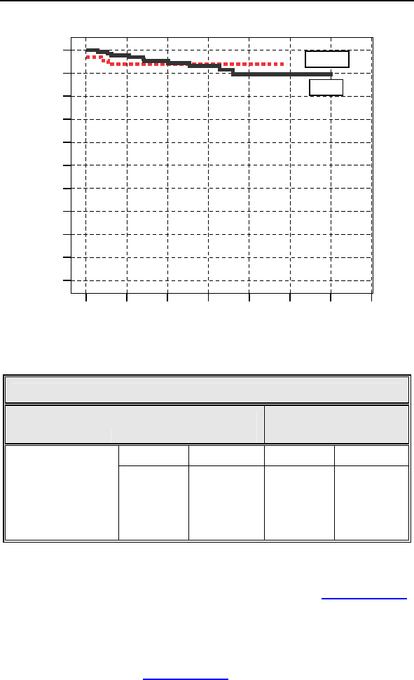
There have been 4 patient deaths reported for the control group
(out of 67 total control patients) and 10 patient deaths have been
reported for the study group (out of 133 total study patients).
None of the deaths were related to the implanted CRT-D system.
One patient in the control group died prior to receiving a
biventricular device implant. There is no significant difference
between the number of deaths in the study group versus the
control group (p = 0.777, Fisher's Exact Test, 2 sided). Table 6
provides a summary of reported patient deaths and Table 7
provides survival percentages by follow-up interval during the first
12 months of study participation.
Table 6: Summary of Patient Deaths
Study
(N = 133)
Control
(N = 67)
Category of
Death
Number of Patients Number of Patients
Sudden Cardiac 1 1
Non-Sudden
Cardiac
5 2
Non-Cardiac 4 1
All Causes 10 4
Figure 3 shows the associated Kaplan-Meier survival curves for
the study and control group. The significance level for the
difference between the two study groups based on a Log Rank
test was p = 0.795.
Lumax Technical Manual 27
211815129630
Survival Time (months)
1.0
0.9
0.8
0.7
0.6
0.5
0.4
0.3
0.2
0.1
0.0
Cumulative Survival
Log Rank = 0.795
Control
Study
Figure 3: Kaplan-Meier Survival Curves
Table 7 Survival Table
Study Group
(n = 133)
Control Group
(n = 66)
Number % Number %
Enrollment 133 100.00% 67 100.00%
3-month 131 98.50% 63 94.03%
6-month 127 95.49% 63 94.03%
12-month 123 92.48% 63 94.03%
1.6 Clinical Studies
The Kronos LV-T Clinical study (HOME-CARE, Section 1.6.1)
supports the safety of the Lumax CRT-D/ICD device family.
Additionally, because the Tupos LV/ATx and the Lumax CRT-D
devices have identical CRT and ventricular ICD therapy, the
effectiveness results from the OPTION CRT/ATx IDE Clinical
study (Tupos LV/ATx, Section 1.6.2) support the effectiveness of
the Lumax family.

28 Lumax Technical Manual
1.6.1 Kronos LV-T Study
The purpose of the HOME-CARE Observational Study is to
demonstrate the safety of the CE-marked Kronos LV-T cardiac
resynchronization defibrillator (CRT-D) in patients with congestive
heart failure (CHF).
1.6.1.1 Methods
The multi-center, non-randomized observational study was
designed to evaluate the safety of the Kronos LV-T through an
analysis of the complication-free rate through three months.
The HOME-CARE Observational Study Primary Endpoint was to
evaluate complications (adverse events that require additional
invasive intervention to resolve) related to the implanted CRT
system which includes the Kronos LV-T, the right atrial lead, the
right ventricular ICD lead, and the left ventricular lead
Inclusion Criteria
To support the objectives of this investigation, patients were
required to meet the following inclusion criteria prior to
enrollment:
Indication for Cardiac Resynchronization Therapy
Sufficient GSM-network coverage in the patient’s area
Age greater than or equal to 18 years
Exclusion Criteria
To support the objectives of this investigation, the exclusion
criteria at the time of patient enrollment included the following:
Permanent atrial fibrillation
Myocardial infarction or unstable angina pectoris within
the last 3 prior to enrollment
Planned cardio-surgical intervention within 3 months after
enrollment (e.g. PTCA, CABG, HTX)
Acute myocarditis
Life expectancy less than 6 months
Pregnant or breast-feeding woman
Drug or Alcohol abuse
The patient is mentally or physically unable to take part in
the observational study
No signed declaration of consent for the patient

Lumax Technical Manual 29
At the enrollment screening, the physician evaluated the patient
to verify that all inclusion/exclusion criteria were met in
accordance to the protocol and the patient signed the informed
consent. After successful enrollment, all patients were implanted
with the Kronos LV-T CRT-D. Evaluations at the One- and Three-
month follow-ups included resting ECG, NYHA classification,
medications, and activation of Home Monitoring.
1.6.1.2 Summary of Clinical Results
The study involved 45 patients (37 males, 82.2%, and 8 females,
17.8%), with a mean age of 64 years (range: 36-79), a left
ventricular ejection fraction of 26 % (range: 15-43), NYHA Class
III (NHYA Class 1 (2.3%), Class II (11.4%), Class III (79.5%),
Class IV (6.8%)) and QRS duration of 154 ms (range: 84-208).
The mean implant duration was 4.5 months with a cumulative
implant duration of 202 months. The patient follow-up compliance
rate was 95.9% out of 221 required follow-ups.
Primary Endpoint
The safety of the Kronos LV-T was evaluated based on
complications (adverse events that require additional invasive
intervention to resolve) related to the implanted CRT system
which includes the Kronos LV-T, the right atrial lead, the right
ventricular ICD lead, and the left ventricular lead. 5 complications
were seen in 3 patients with cumulative implant duration of 202
months (16.8 patient-years). 6.7% of the patients had a reported
complication. The rate of complications per patient-year is 0.30.
The freedom from Kronos LV-T system-related complications is
93.3% with a two sided lower 95% confidence bound of 83.8%.
The null hypothesis is rejected, and it is concluded that the
complication-free rate is equivalent to 85% within 10%.

30 Lumax Technical Manual
1.6.2 Tupos LV/ATx Study
NOTE:
The clinical study information included in this section was
performed with the Tupos LV/ATx CRT-D, which is an earlier
version of the Lumax CRT-D/ICD families. The clinical study
data presented here is applicable because the Lumax family
are downsized versions of the Tupos LV/ATx CRT-D and
Tachos ICD families. The Lumax family is slightly different as
compared to the Tupos LV/ATx (and Tachos family) in the
following areas:
Reduced size from 50/48 cc to 40/35 cc
Addition of Home Monitoring functionality
Addition of triggered pacing for biventricular pacing
modes
True three chamber pacing and sensing capabilities
(CRT-Ds)
1.6.2.1 Study Overview
The purpose of the prospective, randomized, multi-center
OPTION CRT/ATx study was to demonstrate the safety and
effectiveness of the investigational Tupos LV/ATx Cardiac
Resynchronization Therapy Defibrillator (CRT-D) in patients with
congestive heart failure (CHF) and atrial tachyarrhythmias.
Patients in the study group were implanted with a BIOTRONIK
Tupos LV/ATx. Patients in the control group were implanted with
any legally marketed CRT-D. Patients in both the study and
control groups were implanted with a legally marketed left
ventricular lead.

Lumax Technical Manual 31
1.6.2.2 Methods
Primarily, the study evaluates and compares the functional
benefits of CRT between the two randomized groups using a
composite endpoint consisting of a six-minute walk test (meters
walked) and quality of life measurement (assessed using the
Minnesota Living with Heart Failure Questionnaire). Relevant
measurements were completed twice for each patient: once at
the Baseline evaluation (two-week post implant follow-up) and
again at a six-month follow-up evaluation. The data collected
during this clinical study was used to demonstrate equivalent
treatment of CHF in both the study and control groups. This study
also evaluated other outcomes including: the effectiveness of
atrial therapy to automatically convert atrial tachyarrhythmias, the
percentage of time CRT is delivered, and other measures of CHF
status including NYHA classification, peak oxygen consumption
during metabolic exercise testing, and the rate of hospitalization
for CHF.
Inclusion Criteria
To support the objectives of this investigation, patients were
required to meet the following inclusion criteria prior to
enrollment:
Stable, symptomatic CHF status
NYHA Class III or IV congestive heart failure
Left ventricular ejection fraction 35% (measured within
Six-Months prior to enrollment)
Intraventricular conduction delay (QRS duration greater
than or equal to 130 ms)
For patients with an existing ICD/CRT-D, optimal and
stable CHF drug regimen including ACE-inhibitors and
beta-blockers unless contraindicated (stable is defined as
changes in dosages less than 50% during the last 30
days)
Indicated for ICD therapy
History or significant risk of atrial tachyarrhythmias
Willing to receive possibly uncomfortable atrial shock
therapy for the treatment of atrial tachyarrhythmias
Able to understand the nature of the study and give
informed consent
Ability to tolerate the surgical procedure required for
implantation

32 Lumax Technical Manual
Ability to complete all required testing including the six-
minute walk test and cardiopulmonary exercise testing
Available for follow-up visits on a regular basis at the
investigational site
Age greater than or equal to 18 years
Exclusion Criteria
To support the objectives of this investigation, the exclusion
criteria at the time of patient enrollment included the following:
Previously implanted CRT device
ACC/AHA/NASPE indication for bradycardia pacing
(sinus node dysfunction)
Six-minute walk test distance greater than 450 meters
Chronic atrial tachyarrhythmias refractory to
cardioversion shock therapy
Receiving intermittent, unstable intravenous inotropic
drug therapy (patients on stable doses of positive
inotropic outpatient therapy for at least One-Month are
permitted)
Enrolled in another cardiovascular or pharmacological
clinical investigation
Expected to receive a heart transplant within 6 months
Life expectancy less than 6 months
Presence of another life-threatening, underlying illness
separate from their cardiac disorder
Acute myocardial infarction, unstable angina or cardiac
revascularization within the last 30 days prior to
enrollment
Conditions that prohibit placement of any of the lead
systems
1.6.2.3 Summary of Clinical Results
A total of 200 patients were enrolled in the OPTION CRT/ATx
clinical study at 25 sites:
There were 133 study patients and 67 active control patients in
this prospective, multi-center, randomized clinical study. For the
study group, there were 129 successful implants (91.4%) of the
Tupos LV/ATx CRT-D system. For the active control group, there
were 64 successful implants (92.2%) of the legally marketed
CRT-D systems.

Lumax Technical Manual 33
Patient Accountability
After randomization and enrollment, 7 patients (4 in the study
group and 3 in the control group) did not receive an implant. The
reasons for patients not receiving an implant are outlined in
Figure 4.
Enrolled and Randomized
Patients
Study 133
Control 67
No implant Attempted
Withdrawal of Consent
Study 2
Control 1
Not Meeting Inclusion Criteria
Study 1
Control 1
Implant Attempted
Study 130
Control 65
Unsuccessful implant
Withdrawal of IC before 2nd Attempt
Study 1
Control 0
Expired before Second Attempt
Study 0
Control 1
Successful implant
Study 129
Control 64
6-Month Follow-up Data
Patient Death before 6-Month
Study 7
Control 3
Withdrawal before 6-Month
Study 1
Control 2
Not Reached 6-Month FU
or Data Pending
Study 21
Control 10
Patients completed 6-Month
Follow-up
Study 100
Control 49
Figure 4: Patient Accountability
Overall Results
There were 192 endocardial and 19 epicardial leads
implanted in 193 patients. Investigators were allowed to
choose among any legally marketed LV lead according to
familiarity with the lead and patient anatomy. The
Tupos LV/ATx CRT-D was implanted with 7 endocardial
and 4 epicardial lead models from 6 different
manufacturers. There were no adverse events reported
attributable to lead-generator incompatibility.

34 Lumax Technical Manual
The cumulative implant duration was 1240.4 months with
a mean duration of 9.6 months for the study group. The
cumulative implant duration is 596.5 months with a mean
duration of 9.3 months for the control group.
For the study group, there have been 278 adverse events
(210 observations in 104 patients and 68 complications in
50 patients). There has been one unanticipated adverse
device effect reported.
For the control group, there have been 105 adverse
events (81 observations in 44 patients and 24
complications in 19 patients). There have been no
unanticipated adverse device effects reported.
There have been 10 patient deaths reported in the study
group and 4 patient deaths reported in the control group.
The clinical investigators have determined that no deaths
were related to the study device.
1.6.2.4 Primary Endpoint 1: Six Minute Walk Test & QOL
(Effectiveness)
The purpose of Primary Endpoint 1 is to evaluate the
effectiveness of the Tupos LV/ATx system in providing CRT as
measured by the average composite rate of improvement in six
minute walk test and QOL.
Table 8 presents the average composite rate of improvement in
six minute walk test distance and QOL score, the average 6-
minute walk test distance and the average QOL score at Baseline
and at the Six-Month follow-up, as well as the average difference
in 6-minute walk test distance and QOL score between Baseline
and the Six-Month follow-up for the Study and Control Groups for
those patients with six minute walk test data and complete QOL
data at both Baseline and the Six-Month follow-up.

Lumax Technical Manual 35
Table 8: Composite of Six Minute Walk Test and QOL
(Effectiveness)
Category
Study
Group
(N = 74)
Mean SE
Control
Group
(N = 38)
Mean SE
P-value*
Distance Walked at
Baseline
310.51 ±
10.89
288.76 ±
15.37 0.249
Distance Walked at
Six-Months
340.77 ±
12.32
301.84 ±
17.02 0.067
∆ Distance Walked
30.26 ±
10.40
17.27% ±
5.59%
13.08 ±
13.05
8.71% ±
5.26%
0.322
0.326
QOL Score at
Baseline 44.39 ± 2.78 45.53 ± 4.13 0.817
QOL Score at Six-
Months 28.68 ± 2.66 33.95 ± 4.35 0.279
∆ in QOL Score**
15.72± 2.83
19.08% ±
12.21%
11.58 ± 3.45
-13.42% ±
34.54%
0.376
0.281
Composite Rate*** 18.18% ±
7.07%
-2.36% ±
17.73% 0.030
*The calculated p-values are associated with a Student's t-test (2-sided)
of the equality of means in the two groups, except for the p-value of the
composite rate, which is associated with a test of equivalence (non-
inferiority).
**∆ in QOL Score is calculated as the average of the individual
differences between Baseline and Six-Months for each patient. Negative
values for mean ∆ QOL in percent are possible when positive mean
values for absolute changes in QOL are recorded. In some cases, small,
negative changes in absolute QOL scores resulted in relatively large
percentage changes.
***The Composite Rate (=(∆ Distance Walked (%) + ∆ QOL Score (%))/2)
is calculated for each patient and then averaged to obtain the Composite
Rates. For all calculations, a positive number represents improvement
from Baseline to Six-Months.

36 Lumax Technical Manual
1.6.2.5 Effectiveness Endpoint Analysis and Conclusions
A composite rate of six minute walk test and QOL improvement
from Baseline to the Six-Month follow-up is evaluated as a
measure of CRT effectiveness. For this analysis both six minute
walk test and QOL are equally weighted at 50%.
The mean difference in the composite rate between study and
control group was 20.53% with an associated one-sided, 95%
confidence bound is (-6.10%). The p-value for non-inferiority
within 10% is 0.030. The analysis of the composite rate in six
minute walk test distance and QOL score demonstrates that the
study group is non-inferior to the control group and that the
primary effectiveness endpoint was met (p=0.030).
1.6.2.6 Primary Endpoint 2: Complication-Free Rate
(Safety)
The purpose of Primary Endpoint 2 was to evaluate complications
(adverse events that require additional invasive intervention to
resolve) related to the implanted CRT system which includes the
Tupos LV/ATx, the right atrial lead, the right ventricular ICD lead,
the left ventricular lead, and the implant procedure. The target
complication-free rate at Six-Months is 85%.
Table 9 provides the categorized complication rates at 6-months
for the study and the control group as well as a comparison
between the study and the control group.

Lumax Technical Manual 37
Table 9: Complications at 6-Month – Study and Control
Study versus Control
Comparison
Category Study
N = 133
Control
N = 67 Delta 95% CI P-value
Procedure
Related
6 (4.51%) 1
(1.49%)
3.02
%
[-3.64%,
8.45%] 0.428
Atrial Lead
Related
3 (2.26%) 1
(1.49%)
0.76
%
[-5.74%,
5.37%] 1.000
ICD Lead
Related
3 (2.26%) 0 (0%) 2.26
%
[-3.03%,
6.53%] 0.552
LV Lead
Related
26
(19.55%)
9
(13.43%)
6.12
%
[-5.50%,
16.45%] 0.329
Device
Related
7 (5.26%) 5
(7.46%)
-
2.20
%
[-11.42%,
4.77%] 0.541
Other
Medical
Related
9 (6.77%) 2
(2.99%)
3.78
% [-3.82%,
10.13%] 0.341
Total
Procedure,
Lead and
Device
Related
39
(29.32%)
15
(22.39%)
6.94
%
[-6.46%,
19.17%] 0.317
Total 46
(34.59%)
17
(25.37%)
9.21
%
[-4.96%,
21.99%] 0.201
1.6.2.7 Primary Safety Enpoint Analysis and Conclusions
The observed procedure, lead and device related complication-
free rate at 6 months was 70.68%. The 95% confidence interval
for the complication-free rate was [62.16%, 78.25%]. The lower,
one-sided 95% confidence bound for the complication-free rate
was 63.50%. Therefore the procedure, lead and device related
complication-free rate at 6 months did not meet the pre-specified
acceptance criterion for this endpoint.

38 Lumax Technical Manual
1.6.2.8 Post-hoc Safety Analysis
BIOTRONIK did not meet the pre-specified objective performance
criteria of 85% within 10% for the safety endpoint. Therefore, a
post-hoc safety analysis was conducted. It was noted that
79.80% (39 out of 49 events) of the complications were right atrial
lead, right ventricular ICD lead, left ventricular lead and procedure
related. The atrial, ICD and LV leads used during this study are
legally marketed devices.
This post-hoc analysis evaluated the LV lead complications that
were “related” or “possibly related” to the Tupos LV/ATx CRT-D,
but excludes the complications that were “not related” to the
Tupos LV/ATx device (see Table 9). There were 11 patients who
had an attempt to implant the LV lead, but the physician was
unsuccessful in either obtaining coronary sinus (CS) access or
unable to find a stable position for the LV lead. Additionally, there
were 4 patients with a documented LV lead dislodgement that
has no direct relationship to the implanted Tupos LV/ATx.
Table 10: Complications at 6-Months (Excluding LV Lead
Related) - Study versus Control
Category Study
N=133
Control
N=67
Difference
Study vs.
Control
Procedure Related 6 (4.51%) 2 (2.99%) 1.53%
Atrial Lead Related 3 (2.26%) 1 (1.49%) 0.76%
ICD Lead Related 3 (2.26%) 0 (0%) 2.26%
LV Lead Related 11 (8.27%) 1 (1.49%) 6.78%
Device Related 7 (5.26%) 5 (7.46%) -2.20%
Other Medical Related 9 (6.77%) 2 (2.99%) 3.78%
Total Procedure,
Lead and Device
Related
27
(20.30%)
8
(11.94%) 8.36%
Total 35
(26.32%)
10
(14.93%)
11.39%

Lumax Technical Manual 39
The pulse generator related complication rate is higher in the
control group as compared to the study group. The complication
rates for procedure related, atrial lead related, ICD lead related,
LV lead related and other medical related are higher in the study
group as compared to the control group.
1.6.2.9 Post hoc Safety Analysis Conclusion
There are no clinically substantial differences in the total
complication rate or in the rates for the different complication rate
categories between the study and the control group.
Table 11 compares this post-hoc Safety Endpoint analysis to
previous CRT-D clinical studies:
Table 11 Safety Endpoint Comparisons
CRT-D Study
Estimated
freedom from
Complications
@ 6mos.
Lower 95%
CI
95%
lower
bound
criteria
BIOTRONIK OPTION
(Original Analysis) 70.68% 63.5% 75%
BIOTRONIK OPTION
(Post-hoc Analysis) 78.95% 72.29% 75%
Medtronic Insync ICD 81.1% 77.6% 67%
Guidant Contak CD N/A N/A 70%
St. Jude Medical Epic
HF 93.4% 90.6% 70%
This analysis confirms that the safety profile of the Tupos LV/ATx
is within a similar range determined during trials of other legally
marketed CRT-D devices.

40 Lumax Technical Manual
1.6.2.10 Secondary Endpoint Results
1. The purpose of Secondary Endpoint 1 is to evaluate the
overall ability of the Tupos LV/ATx to appropriately convert
spontaneous AT (atrial tachycardia) and AF (atrial fibrillation).
The results from the OPTION study were compared to the
results from BIOTRONIK’s TACT study (P000009/S4, dated
09-09-2002) that demonstrated the effectiveness of these
atrial therapy features in the Tachos DR - Atrial Tx ICD.
Table 12 summarizes success rates for each individual atrial
tachyarrhythmia therapy type and overall success rate from
the OPTION study compared to the TACT study. The number
of episodes and patients receiving any therapy is less than
the total episodes of each therapy type, as episodes may
have included more than one type of therapy.
Table 12 Overall Atrial Conversion Rate
OPTION Study
Patients Success Episodes Conversion
rate
ATP 3 3 5 60.0%
HF Burst 17 45 111 40.5%
Shock 12 30 34 88.2%
All
Therapies 25 78 129 60.5%
TACT Study
ATP 29 62 142 43.6 %
HF Burst 49 156 408 38.2 %
Shock 42 84 108 77.8 %
All
Therapies 66 302 542 55.7 %
The overall conversion rate and the conversion rates for each
therapy are comparable to the conversion rates observed in
the TACT study, demonstrating that the Tupos LV/ATx device
has similar atrial conversion capabilities as the legally
marketed Tachos DR – Atrial Tx ICD.

Lumax Technical Manual 41
2. The purpose of Secondary Endpoint 2 is to evaluate VT
(ventricular tachycardia) and VF (ventricular fibrillation)
detection times of the Tupos LV/ATx. This is a measure of the
ability of the ventricular detection algorithm to detect VT and
VF in an appropriate timeframe. This endpoint was evaluated
based on the review of electrograms following induced VT/VF
episodes. A comparison of data from the TACT study that
utilized the legally marketed Tachos DR – Atrial Tx ICD
(P000009/S4, dated 09-09-2002) to data collected during the
OPTION study for the Tupos LV/ATx was performed.
Table 13 summarizes and compares the results from these
two clinical studies.
Table 13: Summary of Detection Times
Detection
Time
Tachos DR -
Atrial Tx ICD
Mean (SE)/N
Tupos
LV/ATx Mean
(SE)/N
Difference
Individual
Readings 2.27 (0.06)/52 2.26 (0.06)/71 0.01
By Patient 2.27 (0.07)/26 2.24 (0.06)/35 0.03
The analysis demonstrates that the average detection times
of the Tupos LV/ATx are comparable to the detection times
observed with the legally marketed Tachos DR - Atrial Tx
ICD. Both devices utilize identical ventricular detection
algorithms and only sense with the right ventricular lead. This
clinical data demonstrates that the ventricular detection times
are similar in both devices.
3. The purpose of Secondary Endpoint 3 is to evaluate the
percentage of ventricular pacing (thus, CRT) as
demonstrated by the device diagnostics at required follow-
ups. This data was based on diagnostic data stored by the
Tupos LV/ATx.
Table 14 summarizes the percentage of ventricular pacing
between follow-ups as shown by device diagnostics for
patients in the study group.

42 Lumax Technical Manual
Table 14: Percentage of Ventricular Pacing –
3-Month and 6-Month Follow-ups
Percentage of
Ventricular
Pacing
3-Months
Patients
(percentage)
6-Months Patients
(percentage)
<80% 9 (7.4%) 4 (4.0%)
81 – 85 % 4 (3.3%) 2 (2.0%)
86 – 90 % 13 (10.7%) 9 (9.1%)
91 – 95 % 19 (15.7%) 20 (20.2%)
96 – 100 % 76 (62.8%) 64 (64.7%)
Totals 121 (100%) 99 (100%)
The majority of the follow-ups (84.9%) show a percentage of
ventricular pacing of 91% or more at Six-Months.
4. The purpose of secondary endpoint 4 is to evaluate
improvement in functional capacity as measured by the six
minute walk test. The six minute walk test is a well-accepted
measure of functional capacity and exercise tolerance. Also,
this test more closely mimics the patient’s day-to-day
activities than maximal exercise testing.
Table 15 summarizes the six minute walk test distance at
Baseline and the Six-Month follow-up for patients in the study
group and the control group.

Lumax Technical Manual 43
Table 15: Six Minute Walk Distance
Distance
(meters) Study Control
Baseline
N
Mean SE
Range
Median
127
283.14 9.27
23 to 511
302.00
61
269.43 13.77
29 to 507
244.00
Six-Month
N
Mean SE
Range
Median
93
329.73 10.82
78 to 596
335.00
44
310.70 15.49
91 to 489
313.00
* Student's t-test, 2-sided
There are no clinically relevant differences in the six minute
walk test results between the study and the control group.
5. The purpose of Secondary Endpoint 5 is to evaluate the
improvement in the patient’s NYHA classification. Table 16
summarizes the average improvement in NYHA from
Baseline to Six-Months for 140 patients that were able to
complete both NYHA classification evaluations.
Table 16: Improvement in NYHA Classification at Six-
Months from Baseline
NYHA Change During OPTION Study
Change in NYHA
Class
Study Patients
(N=97)
(percentage)
Control Patients
(N=43)
(percentage)
Improved 2 classes 10 (10.3%) 2 (4.7%)
Improved 1 class 47 (48.5%) 20 (46.5%)
Total improved 57 (58.8%) 23 (51.2%)
No change 39 (40.2%) 20 (46.5%)
Worsened 1 class 1 (1.0%) 1 (2.3%)

44 Lumax Technical Manual
The study and the control group have similar NYHA classes
and similar rates of improvement in NYHA class from
Baseline to the Six-Month follow-up.
6. The purpose of Secondary Endpoint 6 is to evaluate the rate
of hospitalization, for CHF and for all other causes. The
occurrence rate and reasons for hospitalization of the study
group were compared to the control group. To be consistent
with other large-scale clinical trials, clinical sites were
instructed to report hospitalizations for CHF using the
following definitions: 1) hospitalization for heart failure
management, 2) outpatient visit in which IV inotropes or
vasoactive infusion are administered continuously for at least
4 hours, or 3) emergency room (ER) visit of at least 12 hours
duration in which intravenous heart failure medications
including diuretics are administered.
Table 17 summarizes hospitalization, ER visits and outpatient
visits for enrolled patients.

Lumax Technical Manual 45
Table 17: Hospitalization, ER Visits and Outpatient Visits
Medical Visits Study
(N=128)
Control
(N=65)
Hospital
Admissions
Patients
Hospitalizations
Patients
Hospitalizations
CHF Related:
20 (15.6%)
28
All causes:
68 (53.1%)
76
CHF Related:
5 (7.7%)
9
All causes:
29 (44.6%)
46
Emergency
Room Visits
Patients
Visits
Patients
Visits
CHF Related:
1 (0.8%)
1
All causes:
13 (10.1%)
16
CHF Related:
0 (0.0%)
0
All causes:
2 (3.1%)
2
Outpatient Visits
Patients
Visits
Patients
Visits
CHF Related:
1 (0.8%)
1
All causes:
5 (3.9%)
5
CHF Related:
0 (0.0%)
0
All causes:
2 (3.1%)
2
A large percentage of All Cause hospitalizations can be
attributed to pacing lead revisions, device infections, or other
device-related interventions (e.g., pocket revision or device
replacements for ERI or device recall). The CHF
hospitalization rate for both the study and control groups is
clinically acceptable considering the enrollment CHF status of
the patients.

46 Lumax Technical Manual
7. The purpose of Secondary Endpoint 7 is to evaluate the
observation rate. Observations are defined as clinical events
that do not require additional invasive intervention to resolve.
For the study group, there were 210 observations in 104
patients with cumulative implant duration of 1240.4 months
(101.9 patient years). 78.2% of the enrolled study patients
have a reported observation. The rate of observations per
patient-year is 2.06. For the control group, there were 81
observations in 44 patients with cumulative implant duration
of 596.5 months (49.0 patient years). 65.7% of the enrolled
control patients had a reported observation. The rate of
observations per patient-year was 1.65.
8. The purpose of Secondary Endpoint 8 is to evaluate peak
VO2 as a measure of effectiveness of the Tupos LV/ATx
system in providing CRT. The core lab was blinded to study
randomization assignments during evaluation of the results of
the cardiopulmonary exercise (CPX) testing in order to
minimize the potential for bias. According to the protocol, to
be included in the analysis, patients were required to attain a
respiratory exchange ratio (RER) of 1.
Table 18 provides a summary of peak VO2 results for 42
patients with CPX testing completed at Baseline and the Six-
Month follow-up and with an RER of 1.

Lumax Technical Manual 47
Table 18: Peak VO2 Testing Results – Patients with RER
1
Results Study Control
Peak VO2
(ml/kg/min)
N=32
Baseline:
Mean:
13.46 ± 0.57
Range:
6.9 to 21.1
Six-Month:
Mean:
13.39 ± 0.53
Range:
7.6 to 20.70
Difference:
Mean:
-0.06 ± 0.42
Range:
-7.9 to 4.9
N=10
Baseline:
Mean:
12.58 ± 0.75
Range:
8.0 to 14.8
Six-Month:
Mean:
12.89 ± 0.94
Range:
7.0 to 17.2
Difference:
Mean:
0.31 ± 0.67
Range:
-2.7 to 4.6
1.6.2.11 Multi-site Poolability and Gender Analysis
The OPTION CRT/ATx clinical report includes data from multiple
centers with centralized coordination, data processing, and
reporting at BIOTRONIK. All of the clinical centers followed the
requirements of an identical clinical protocol, and all of the clinical
centers used the same methods to collect and report the clinical
data. In order to justify pooling of the data from multiple centers,
several analyses were completed. All of the centers were divided
into two groups based on implant volume. Comparisons were
then made between the patient populations based on the results
of each of the endpoints. Additionally, analyses were performed
on the data collected in the OPTION CRT/ATx clinical
investigation in order to compare results between males and
females. The first type of analysis compared enrollment by patient
gender in each of the study and control groups. The second type
of analysis compared effectiveness outcomes in each gender.
The results of these analyses demonstrate poolability of the data
between sites. There were no significant differences in the
second primary endpoint or any of the secondary endpoints
between high and low volume implant centers.

48 Lumax Technical Manual
The gender distribution in this clinical investigation is consistent
within the study groups and includes a representative proportion
of female participants. There were no significant differences in
any of the primary or secondary endpoints between the male and
female population.
1.6.2.12 Conclusions
The IDE Clinical study (OPTION LV/ATx) demonstrated that the
safety and effectiveness of the Tupos LV/ATx CRT-D device is
equivalent to that of similar legally marketed CRT-D devices.
Although the study missed its primary safety endpoint, additional
post hoc analyses were conducted to reassure that the safety
profile of the device is comparable to other legally marketed
CRT-D devices.
1.6.3 Lumax HF-T V-V Clinical Study
1.6.3.1 Study Overview
The Lumax HF-T V-V clinical study is a randomized, double-
blinded, crossover, multi-center, prospective trial. The purpose of
the study is to assess the safety and efficacy of adding
programmable V-V delay biventricular pacing when used as part
of echo optimization of V-V timing (OPT). The assessment
consisted of comparing one-month periods of CRT with (OPT)
and without (SIM) V-V programmability and optimization in the
same patients to assess whether a statistically significant
increase of worsened HF status occurred during V-V adjustment.
The V-V delay feature is programmed to provide CRT through the
selection of the first chamber paced and adjustment of the V-V
delay. When V-V delay programmability is not available, CRT
provides simultaneous biventricular pacing (V-V delay is 0 ms).

Lumax Technical Manual 49
1.6.3.2 Methods
The study primarily evaluates and compares the functional
benefits of the Lumax HF-T with OPT versus the Lumax HF-T
with SIM using an endpoint that includes both a 6-minute walk
(6MW) test and quality of life (QOL) measurement assessed
using the Minnesota Living with Heart Failure questionnaire
(MLWHFQ). As such, relevant measurements are completed 3
times for each patient: once at the baseline evaluation (up to 14
days after enrollment), once at the 1-month follow-up (30 days
after baseline) and once at the 2-month follow-up (30 days after
the 1-month follow-up). Baseline data is collected with the
Lumax HF-T programmed to SIM.
6MW testing was chosen as a meaningful measure of CRT
therapy effect on HF status because 6MW has been shown to
improve during chronic CRT therapy (Olsson LG, Swedberg K,
Clark AL et al. Six minute corridor walk test as an outcome
measure for the assessment of treatment in randomized, blinded
intervention trials of chronic heart failure: a systematic review. Eur
Heart J 2005; 26:778–793.) Example improvements of 6MW
include increase in the range of 20 meters.
In this trial, the intent was to detect any loss of CRT benefit by
assessing the incidence of HF “worsening”, defined as reduction
of 35 meters distance on 6MW during CRT with V-V
programmability and optimization compared to during CRT
without V-V programmability and optimization.
QOL testing was chosen as a meaningful measure of CRT
therapy effect on HF status because QOL has been shown to
improve during chronic CRT therapy (Albouaini K, Egred M, Rao
A, et al. Cardiac resynchronisation therapy: evidence based
benefits and patient selection. Eur J Intern Med. 2008
May;19(3):165-72) Example magnitude improvements of QOL
include change in the range of 10 points.
In this trial, the intent was to detect any loss of CRT benefit by
assessing the incidence of HF “worsening”, defined as increase
of 10 points in QOL score by MLWHFQ during CRT with V-V
programmability and optimization compared to during CRT
without V-V programmability and optimization.
Worsening in the trial was defined as either a worsening (as
defined) in 6MW or in QOL score during CRT with V-V
programmability and optimization.

50 Lumax Technical Manual
The primary endpoint hypothesis required that a high proportion
of subjects remain “not worsened” when CRT with V-V
programmability and optimization was delivered compared to
when CRT without V-V programmability and optimization. A high
proportion was defined according to an Objective Performance
Criteria (OPC), derived from observations of how often stable
subjects in the BIOTRONIK Tupos LV/ATX CRT-D trial (OPTION)
experienced spontaneous worsening due to the underlying
disease among other factors.
During the Lumax V-V clinical study, the V-V optimization was
completed utilizing echocardiography specifically determining an
optimal V-V delay using the velocity time integral (VTI) to non-
invasively measure stroke volume. The assessment was
performed by determining the V-V delay setting associated with
the largest VTI value. The VTI of the aortic flow is measured in
the apical 5 chamber view.
Prior to the V-V delay optimization procedure, each patient
underwent an optimization of AV timing. Following the AV timing
adjustment, this standardized procedure was followed for the
optimization of V-V delay:
1. Program the Lumax HF-T “Initially Paced Chamber”
parameter to either RV or LV based on preference.
2. Assess the VTI measurement at the following V-V delays
(additional V-V settings may be utilized at the investigator’s
discretion):
100 ms
80 ms
60 ms
40 ms
20 ms
0 ms
Note: Use the average VTI parameter over a 3 beat cycle and
wait 10 to 15 seconds between changing V-V delay settings.
Also, attempt to measure the VTI parameter within the same
patient respiratory cycle.
3. Record the VTI measurement associated with each V-V
delay setting
Repeat steps 1-3 for the remaining “Initially Paced Chamber”
parameters

Lumax Technical Manual 51
Select permanent “Initially Paced Chamber” and “V-V delay after
Vp” to reflect the maximum VTI measurement for final
programming.
Inclusion Criteria
To support the objectives of this investigation, the inclusion
criteria at the time of patient enrollment for this investigational
study included the following requirements:
Meet the indications for therapy.
Successfully implanted with a BIOTRONIK Lumax HF-T
CRT-D system and have received SIM for a minimum of
30 days prior to enrollment.
Treated with stable and optimal CHF medications.
Age ≥ 18 years.
Able to understand the nature of the study and give
informed consent.
Able to complete all testing required by the clinical
protocol, including the 6-minute walk test and QOL
questionnaire.
Available for follow-up visits on a regular basis at the
investigational site.
Exclusion Criteria
To support the objectives of this investigation, the exclusion
criteria at the time of patient enrollment included the following
requirements:
Meet one or more of the contraindications.
Have a life expectancy of less than 6 months.
Expected to receive heart transplantation within 6
months.
Have had more than 1 CHF-related hospitalization within
past 30 days.
Currently receiving IV inotropic medications.
Chronic atrial fibrillation.
Enrolled in another cardiovascular or pharmacological
clinical investigation, except for FDA required post-market
registries.
Any condition preventing the patient from being able to
perform required testing.

52 Lumax Technical Manual
Presence of another life-threatening, underlying illness
separate from their cardiac disorder.
1.6.3.3 Summary of Clinical Results
The study involved 122 patients (96 males, 78.7%, and 26
females, 21.3%), with a mean age of 67.1 years (range: 35-87).
The cumulative enrollment duration is 621.3 months with mean
enrollment duration of 5.1 months. The patient follow-up
compliance rate for all enrolled patients is 98.5% (394 of 400
required follow-ups).
1.6.3.3.1 Primary Endpoint 1: Effectiveness of the V-V Delay
Feature
The primary endpoint was intended to detect whether V-V
programmability and optimization contributed to significantly more
patients with “worsened” HF. Worsened was defined as:
For 6MW, reduction of 35 meters distance on 6MW
during CRT with V-V programmability and optimization
compared to during CRT without V-V programmability
and optimization
For QOL score, increase of 10 points in QOL score by
MLWHFQ during CRT with V-V programmability and
optimization compared to during CRT without V-V
programmability and optimization
For each patient, i.e. as a responder’s analysis, the
occurrence of either worsened 6MW or QOL score during
CRT with V-V programmability and optimization.
Table 19 presents the mean 6-minute walk test distances and
QOL scores for Group 1 and Group 2 patients at the baseline, 1-
month and 2-month follow-ups. Table 19 reports unpaired patient
data for information purposes, with the primary endpoint analysis
utilizing paired data from the 1-month and 2-month follow-ups.

Lumax Technical Manual 53
The analysis of the primary effectiveness endpoint is an intention-
to-treat analysis based on the responder classification of changes
in the MLWHFQ and 6-minute walk distance between periods of
SIM and OPT, obtained at the 1-month and 2-month follow-ups.
Table 20 presents the percentage of all patients worsened and
not worsened to evaluate the effectiveness of OPT vs. SIM
utilizing the QOL and 6-minute walk responder classification. A
total of 106 out of the 110 patients that completed the primary
endpoint follow-up met the primary endpoint analysis based on
paired QOL and 6-minute walk data at the 1-month and 2-month
follow-up visits.
Table 19. QOL and 6-Minute Walk Test Results (Effectiveness)
Category Group 1 Group 2
QOL score at baseline N = 60
35.4 ± 23.0
N = 53
30.0 ± 21.6
QOL score at 1-month
follow-up
N = 57
31.2 ± 24.0
OPT
N = 54
30.1 ± 22.5
SIM
QOL score at 2-month
follow-up
N = 58
32.6 ± 25.5
SIM
N = 52
25.9 ± 19.8
OPT
Distance walked at
baseline (m)
N = 61
328.9 ± 152.8
N = 54
309.1 ± 139.7
Distance walked at 1-
month follow-up (m)
N = 58
343.9 ± 161.8
OPT
N = 54
337.6 ± 160.7
SIM
Distance walked at 2-
month follow-up (m)
N = 57
341.1 ± 152.6
SIM
N = 51
334.7 ± 148.9
OPT

54 Lumax Technical Manual
Table 20. QOL and 6-Minute Walk Responder Classification
(Effectiveness)
QOL Group 1
(N = 56)
Group 2
(N = 52)
Total
(N = 108)
Worsened 9 (16.1%) 6 (11.5%) 15 (13.9%)
Not worsened 47 (83.9%) 46 (88.5%) 93 (86.1%)
6-Minute Walk (N = 56) (N = 51) (N = 107)
Worsened 14 (25.0%) 15 (29.4%) 29 (27.1%)
Not worsened 42 (75.0%) 36 (70.6%) 78 (72.9%)
Composite (N = 55) (N = 51) (N = 106)
Worsened 21 (38.2%) 18 (35.3%) 39 (36.8%)
Not worsened 34 (61.8%) 33 (64.7%) 67 (63.2%)
The estimate of the proportion of subjects who were classified as
“Not Worsened” was 63.2% (67/106). The lower, exact, one-sided
95% confidence bound for this observed proportion is 54.8%. The
difference between the performance goal of 63% and 54.8% is
8.2%. This is lower than the pre-specified clinically significant
difference () of 12%.
1.6.3.3.2 Primary Endpoint 2: Safety of the V-V Delay
Feature
The purpose of Primary Endpoint 2 is to evaluate adverse events
that require additional invasive intervention to resolve, specifically
related to the V-V delay feature of the Lumax HF-T. These
adverse events include any software issues related to V-V delay
programming or any adverse event that occurs after V-V delay
optimization and that can be directly attributed to the use of the
V-V delay feature.
There have been 0 reported complications related to the V-V
delay feature for the 122 patients enrolled into the study.

Lumax Technical Manual 55
The observed complication-free rate was 100.0%. The lower,
exact, one-sided 95% confidence bound for this observed rate is
97.6%. This exceeds the pre-specified rate (90% - δ) required for
demonstrating non-inferiority.
1.6.3.4 Conclusions
The cumulative enrollment duration is 621.3 months with a mean
duration of 5.1 months. Sixty-one (50.0%) of the patients have
been enrolled for 91-180 days.
The proportion of subjects who are “Not Worsened” while their
device was programmed to OPT was found to be not inferior to
the performance goal of 63% within 12%. In addition, there have
been 0 complications reported regarding the Lumax HF-T V-V
delay feature.
The data received and analyzed demonstrates the general safety
of the Lumax HF-T V-V timing feature, with 0 complications
reported as caused by the feature. Also, the data received and
analyzed demonstrates the effectiveness of the Lumax HF-T V-V
timing feature, by providing evidence of non-inferiority to
simultaneous biventricular pacing in a responder classification.
1.6.4 TRUST Clinical Study
1.6.4.1 Study Overview
The TRUST study is a multi-center, prospective and randomized
trial. The purpose of the study was to demonstrate that the use of
the BIOTRONIK Home Monitoring system (HM) can safely reduce
the number of regularly scheduled office follow up visits,
compared to the conventional method of ICD follow-up. The
assessment consists of comparing the number of in-office follow-
ups for patients with HM (HM group) versus patients without HM
(Control group). With the use of HM, the number of in-office follow
up visits per year could be reduced from an expected five
scheduled office follow up visits (3, 6, 9, 12 and 15 months) to two
visits (3 and 15 months). Additionally, the time from onset to
evaluation of arrhythmias in both groups was compared. It was
expected that evaluation of cardiac events in the HM arm would
occur earlier than those in the Control group.

56 Lumax Technical Manual
1.6.4.2 Methods
All enrolled patients received a BIOTRONIK ICD with Home
Monitoring/IEGM-Online technology and were randomized to
either Group 1 (Home Monitoring (HM)) or Group 2 (No Home
Monitoring (Control)) using a randomization ratio of 2:1.
Group 1 (HM)
Device evaluations for scheduled follow-ups, patient-initiated
inquiries and event triggered notifications were performed with
HM/IEGM Online. Patients were scheduled for office device
interrogations only at the 3 month and 15 month follow-up points
(following the HM online check). At 6, 9 and 12 months, a HM
check was performed first. Investigators may then elect to
perform an office device interrogation if they determine that it is
necessary after reviewing the HM data.
Group 2 (Control)
Patients were evaluated using conventional, calendar-based
office visits at 3, 6, 9, 12 and 15 months post-implant. Interim
visits were made according to physician discretion (e.g. following
any ICD discharges or symptoms). Home Monitoring was
programmed OFF for the duration of the study.
HM Event Triggered Device Evaluations
Investigators with patients in Group 1 (HM) may receive HM
notifications in response to pre-programmed events such as VT1
detected and SVT detected. Upon the receipt of a HM Event
Notification, investigators reviewed the notification and the
associated information on the HM/IEGM-Online website and
recorded the type of event and what type of action, if any, was
taken as a result of this notification.
Patient-Initiated Device Evaluations
Investigators may be contacted by the patient for
device/arrhythmia-related care (e.g. perceived device discharge,
symptoms). For patients in Group 1 (HM), investigators triaged
the complaint using the Home Monitoring website. Investigators
recorded if the information from Home Monitoring was sufficient.
For patients in Group 2 (Control), the complaint was assessed
per standard of care or normal clinic procedures.

Lumax Technical Manual 57
Primary Endpoints
The purpose of primary endpoint 1 (HM efficacy) was to compare
the number of in-office ICD follow-ups for patients in Group 1
(HM) to the conventional, calendar-based method of ICD follow-
up as in Group 2 (Control).
The purpose of the primary endpoint 2 (safety) was to compare
the Safety Event Rate (SER), which includes death, incidence of
strokes and events requiring surgical interventions (e.g. device
explants or lead revision) between the two groups.
Secondary Endpoints
The purpose of secondary endpoint 1 was to compare AF, VT
and VF events between Group 1 and Group 2 in terms of the
number, categories, and detection time relative to onset.
Inclusion Criteria
To support the objectives of this investigation, the inclusion
criteria at the time of patient enrollment for this investigational
study included the following requirements:
Implanted within the last 45 days or being considered for
implant with a BIOTRONIK ICD with Home
Monitoring/IEGM-Online technology
Able to utilize the HM system throughout the study
Ability to give informed consent
Geographically stable and able to return for regular
follow-ups for fifteen (15) months
At least 18 years old
Exclusion Criteria
To support the objectives of this investigation, the exclusion
criteria at the time of patient enrollment included the following
requirements:
Patients who do not fulfill all inclusion criteria
Patients who are pacemaker dependent
Currently enrolled in any other cardiac clinical
investigation.

58 Lumax Technical Manual
Clinical Events Committee
The Clinical Events Committee (CEC) is an advisory review board
comprised of three physicians that are not participating in the
TRUST Study who reviewed and adjudicated all deaths, strokes,
surgical interventions, and cardiac adverse events that occur
during the study. The CEC also reviewed all divergent
classifications of actionable vs. non-actionable office follow up
visits between the physician and BIOTRONIK, and reviewed a
random sampling of 1% of office follow up visits in which there is
no disputed classification.
1.6.4.3 Summary of Clinical Results
The study involved 1443 patients (1038 males, 71.9%), with a
mean age of 63.5 years (range: 20-95). The cumulative
enrollment duration is 18,367 months with mean enrollment
duration of 12.7 months. The patient follow-up compliance rate for
all enrolled patients is 87.5% in Group 1 and 78.8% in Group 2.
1.6.4.3.1 Primary Endpoint 1: Home Monitoring
Effectiveness
The purpose of primary endpoint 1 (HM efficacy) was to compare
the number of in-office ICD follow-ups for patients in Group 1
(HM) to the conventional, calendar-based method of ICD
follow-up as in Group 2 (Control).
Detailed primary endpoint 1 results are presented in Table 21.
Table 21: Primary Endpoint Group 1 vs. Group 2
Office Follow-up Visits
No. of
Pts** Scheduled Unscheduled Total
Group 1
(HM) 898
n = 991
1.3 ± 1.0 per pt yr
13.1% actionable
n = 401
0.6 ± 1.7 per pt yr
29.7% actionable
1.9 ± 1.9
per pt yr
Group 2
(Control) 414
n = 1110
3.0 ± 1.1 per pt yr
10.7% actionable
n = 117
0.4 ± 1.4 per pt yr
29.1% actionable
3.4 ± 1.7
per pt yr
p value < 0.001 0.032
< 0.001
* Up to and including 12 month follow-up data
** Number of patients that have contributed at least 1 follow-up

Lumax Technical Manual 59
Analysis
The comparison of the number of 3, 6, 9, and 12 month and
unscheduled office follow-up visits in Group 1 versus Group 2
showed that there was an average number of 1.9 office follow-up
visits on a per year basis in Group 1 (HM) and an average
number of 3.4 office follow-up visits on a per year basis in Group
2 (Control). Therefore, the null hypothesis (HØ) can be rejected,
indicating that the average number of office visits per year is
statistical significantly less in the HM group than in the Control
group (p < 0.001). The primary effectiveness endpoint was met.
1.6.4.3.2 Primary Endpoint 2: Safety Event Rate
The purpose of the primary endpoint 2 was to compare the Safety
Event Rate (SER), which includes death, incidence of strokes and
events requiring surgical interventions (e.g. device explants or
lead revision) between the two groups.
Table 22 summarizes the Safety Event Rate for the study
patients for 12 months post-enrollment. Figure 5 shows these
data in a Kaplan-Meier analysis.
Table 22: Safety Event Rate Comparison
Safety Event Rate* Group 1 Group 2 p value**
Type of Event
Death
Stroke
Surgical
intervention
36/608 (5.9%)
2/574 (0.3%)
57/605 (9.4%)
18/245 (7.3%)
3/227(1.3%)
22/239 (9.2%)
0.440
0.141
1.000
Any Event 95/643 (14.8%) 42/256 (16.4%) 0.539
* Only includes events occurring within 12 months of enrollment
** 2-sided Fisher Exact test
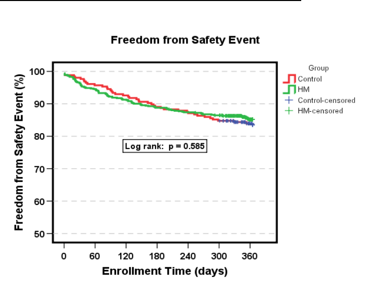
60 Lumax Technical Manual
Figure 5: Safety Event Rate Kaplan Meier
Analysis
The safety event rate for a 12-month duration was 14.8% for
Group 1 (HM) and 16.4% for Group 2 (Control), with a non-
inferiority p-value of 0.005. Therefore, the safety event rate for
HM Group was non-inferior to the safety event rate for the Control
Group within 5%. The upper, one-sided 95% confidence bound
for the difference was 2.7%.
A rejection of the null hypothesis indicates that the safety event
rate for Group 1 (HM) is equivalent (non-inferior) to that of Group
2 (Control).
1.6.4.3.3 Secondary Endpoint 1: Early Detection of Cardiac
Events (AF, VT & VF)
The purpose of secondary endpoint 1 was to compare AF, VT
and VF events between Group 1 and Group 2 in terms of the
number, categories, and detection time relative to onset.

Lumax Technical Manual 61
Table 23 compares the time from onset to evaluation of the first
AF, VT and VF events for each patient that have occurred in each
group, as well as the first of any type of event for each patient in
each group. Figure 6 illustrates the time from onset to evaluation
of arrhythmic events in a box plot graph.
Table 23: Time from First Event Onset to Evaluation
Time from Event Onset
to Evaluation of First
Event/Patient
Group 1
N=972
Group 2
N=471 p value
AF
Median
Mean ± SD (days)
Min
Max
# of patients with events
5.0
25.2 +/- 34.2
0
171
73 (7.5%)
39.5
46.8 +/- 33.7
1
114
28 (5.9%)
p < 0.001
p = 0.005
VT1 & VT2
Median
Mean ± SD (days)
Min
Max
# of patients with events
2.0
12.9 +/- 33.8
0
256
149 (15.3%)
32.0
46.6 +/- 46.9
0
245
53 (11.2%)
p < 0.001
p < 0.001
VF
Median
Mean ± SD (days)
Min
Max
# of patients with events
1.0
10.5 +/- 22.2
0
145
236 (24.3%)
35.5
45.0 +/- 47.0
0
287
92 (19.5%)
p < 0.001
p < 0.001
SVT
Median
Mean ± SD (days)
Min
Max
# of patients with events
2.0
16.6 ± 27.4
0
108
94 (9.7%)
39.0
42.1 ± 35.6
0
157
35 (7.4%)
p < 0.001
p < 0.001
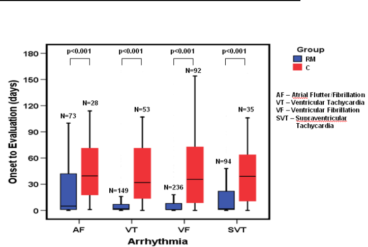
62 Lumax Technical Manual
Figure 6: Median Time from Onset to Evaluation of
Arrhythmic Events
Analysis
The mean time from onset to evaluation of first AF, VT, and VF
events in Group 2 is greater than the mean time from onset to
evaluation of first AF, VT, or VF events in Group 1. A rejection of
the null hypothesis for AF, VT and VF event types indicates that
the mean time from onset to evaluation of the first AF, VT and VF
events in Group 1 is significantly less than the mean time from
onset to evaluation of the first AF, VT and VF events in Group 2.
P-values are =0.005, <0.001 and <0.001 respectively.
1.6.4.4 Conclusions
Use of HM in Group 1 resulted in an average of 1.9 office
visits per patient year in the 12 months post-implant, versus
an average of 3.4 office visits per patient year in Group 2, a
44% reduction in office visits. The average number of office
visits is significantly less in the HM group than in the Control
group (p < 0.001).

Lumax Technical Manual 63
The safety event rate for a 12 month duration for Group 1
(HM) was non-inferior to the safety event rate for Group 2
(Control) within 5% (p = 0.005). The upper, one-sided 95%
confidence bound for the difference was 2.7%.
The mean time from onset to evaluation of AF, VT and VF
events indicates that those events for Group 1 patients are
evaluated in significantly less time when compared to Group
2 patients (AF p = 0.005, VT p < 0.001, VF p < 0.001).
1.6.5 Deikos A+
NOTE:
The clinical study information included in this section was
performed with the Deikos A+ ICD and the Kainox VDD ICD
lead. Due to the similarities in detection and therapy a clinical
study of the Lumax 540 VR-T DX with the Kainox A+ was not
performed.
The Deikos A+ was formed on the Tachos DR platform,
whereas the Lumax 540 VR-T DX was formed on the
Lumax DR-T platform. Both ICDs are designed to be used
with a VDD lead. In this study, the Kainox VDD lead (single
shock RV shock coil and dual atrial floating dipoles) was
implanted. In order to enhance the intrinsic signal from the
floating dipoles, both ICDs contain an atrial sensing amplifier.
The signal is amplified 4 times in the Deikos A+ and 5 times
in the Lumax 540 VR-T DX.
Both the Kainox VDD and the Kainox A+ ICD leads have
identical floating electrodes in the atrium and identical pacing
electrode tip, ring and shock electrodes designed for
placement in the right ventricle. The minor differences are in
the ventricular shock coil (Kainox A+ coil has a slightly larger
surface area, and the surface is not coated with fractal
iridium).

64 Lumax Technical Manual
1.6.5.1 U.S. Clinical Study
1.6.5.1.1 Patients Studied
The Single-Lead ICD system clinical study involved 9 patients (7
males and 2 female) with a mean age of 58.8 years (range: 25 to
83 years). 66.7% presented with ventricular
fibrillation/polymorphic ventricular tachycardia as their primary
tachycardia. The Single-Lead ICD system was selected for the
diagnostic value of the atrial EGMs in 88.9% of the patients.
1.6.5.1.2 Methods
The feasibility clinical investigation was designed to evaluate the
quality of atrial signals obtained using the Single-Lead ICD. The
study was also designed to evaluate the safety and effectiveness
of the Single-Lead ICD system to detect and treat monomorphic
ventricular tachycardia (MVT), polymorphic ventricular
tachycardia (PVT), ventricular fibrillation (VF), and bradycardia.
The specific predefined objectives of the investigation included
UADE-free survival rate, appropriate bradycardia sensing and
pacing, detection and treatment of ventricular tachyarrhythmias
and appropriate atrial sensing during activities of daily living.
1.6.5.1.3 Results
The mean implant duration was 6.1 ± 9.4 months with a
cumulative implant duration of 54.5 months. There were 5
patients followed for over six months and 2 patients followed for
over three months. The patient follow-up compliance rate was
100%, 43 out of 43 required follow-ups.
Table 24 provides a summary of the results of the study group.
Table 24: Clinical Study Results
Description Results
UADE-free Survival Rate 100% (9/9)

Lumax Technical Manual 65
Description Results
Complication Rate 11.1% (1/9)
Appropriate Atrial Sensing Rate1 97.6% (41/42)
Appropriate Atrial Sensing during 24-hour
Holter Test 100% (9/9)
Appropriate Atrial Sensing during
Exercise Treadmill Test 100% (6/6)
Detection and Conversion of Ventricular
Tachyarrhythmias2 100% (68/68)
1.6.5.2 European Clinical Study
1.6.5.2.1 Patients Studied
The European Deikos A+/Kainox VDD lead clinical study involved
82 patients (66 males and 16 female) with a mean age of 61.8
years (range: 29 to 84 years). 42.7% presented with
monomorphic ventricular tachycardia as their primary
tachycardia.
1 The investigator determined the appropriateness of atrial sensing. The rate is
determined by the number of appropriate atrial sensing evaluations divided by
the total number of evaluations.
2 Conversion data were collected in the clinical study for both induced and
spontaneous ventricular tachyarrhythmia episodes. Therefore, both types of
tachyarrhythmia episodes were included in the analysis.

66 Lumax Technical Manual
1.6.5.2.2 Study Objectives
This clinical investigation was designed to collect information on
the performance and function of the Deikos A+/Kainox VDD ICD
system. The specific predefined objectives of the investigation
included the rate of inappropriate, i.e. unnecessary deliveries of
antitachycardia therapy due to supraventricular tachycardia
(SVT), the tachyarrhythmia conversion efficacy of the system with
activated SMART Detection™ algorithm, the rate of appropriate
atrial sensing and the morbidity rate.
1.6.5.2.3 Results
The mean implant duration was 8.9 ± 4.4 months with a
cumulative implant duration of 732 months. No unanticipated
adverse events were reported during the study. There were two
deaths reported, which were unrelated to the implanted device. A
summary of the results obtained during the evaluation is provided
in Table 25 .
Table 25: OUS Clinical Study Results
Description Results
UADE-free Survival Rate 100% (82/82)
Complication Rate 19.5% (16/82)
Inappropriate Therapies with SMART
Detection™ algorithm ON Rate 94.8% (234/250)
Inappropriate Therapies with SMART
Detection™ algorithm OFF Rate 84.7% (133/157)
Appropriate Atrial Sensing Rate1 92.7% (165/211)
Detection and Conversion of Ventricular
Tachyarrhythmias2 100% (211/211)
1 The investigator determined the appropriateness of atrial sensing. The rate is
determined by the number of appropriate atrial sensing evaluations divided by the
total number of evaluations.
2 Conversion data were collected in the clinical study for both induced and
spontaneous ventricular tachyarrhythmia episodes. Therefore, both types of
tachyarrhythmia episodes were included in the analysis.

Lumax Technical Manual 67
1.7 Patient Selection and Treatment
1.7.1 Individualization of Treatment
Determine whether the expected device benefits
outweigh the possibility of early device replacement for
patients whose ventricular tachyarrhythmias require
frequent shocks.
Determine if the device and programmable options are
appropriate for patients with drug-resistant
supraventricular tachyarrhythmias (SVTs), because drug-
resistant SVTs can initiate unwanted device therapy.
Direct any questions regarding individualization of patient
therapy to your BIOTRONIK representative or
BIOTRONIK technical services at 1-800-547-0394.
The prospective patient’s size and activity level should be
evaluated to determine whether a pectoral or abdominal implant
is suitable. It is strongly recommended that candidates for an
ICD/CRT-D have a complete cardiac evaluation including EP
testing prior to device implant to gather electrophysiologic
information, including the rates and classifications of all the
patient’s cardiac rhythms. When gathering this information,
delineate all clinically significant ventricular and atrial arrhythmias,
whether they occur spontaneously or during EP testing.
If the patient’s condition permits, use exercise stress testing to do
the following:
Determine the maximum rate of the patient’s normal
rhythm.
Identify any supraventricular tachyarrhythmias.
Identify exercise-induced tachyarrhythmias.
The maximum exercise rate or the presence of supraventricular
tachyarrhythmias may influence selection of programmable
parameters. Holter monitoring or other extended ECG monitoring
also may be helpful.

68 Lumax Technical Manual
If the patient is being treated with antiarrhythmic or cardiac drugs,
the patient should be on a maintenance drug dose rather than a
loading dose at the time of pulse generator implantation. If
changes to drug therapy are made, repeated arrhythmia
inductions are recommended to verify pulse generator detection
and conversion. The pulse generator also may need to be
reprogrammed.
Changes in a patient’s antiarrhythmic drug or any other
medication that affect the patient’s normal cardiac rate or
conduction can affect the rate of tachyarrhythmias and/or efficacy
of therapy.
If another cardiac surgical procedure is performed prior to
implanting the pulse generator, it may be preferable to implant the
lead system at that time. This may prevent the need for an
additional thoracic operation.
1.7.2 Specific Patient Populations
Pregnancy - If there is a need to image the device, care should
be taken to minimize radiation exposure to the fetus and the
mother.
Nursing Mothers - Although appropriate biocompatibility testing
has been conducted for this implant device, there has been no
quantitative assessment of the presence of leachables in breast
milk.
Geriatric Patients - Most (about 71%) of the patients receiving a
CRT-D or ICD in the clinical studies detailed in this manual were
over the age of 60 years (see Clinical Studies).
Handicapped and Disabled Patients - Special care is needed in
using this device for patients using an electrical wheel chair or
other electrical (external or implanted) devices.
1.8 Patient Counseling Information
The implanted devices are subject to random component failure.
Such failure could cause inappropriate shocks, induction of
arrhythmias or inability to sense arrhythmias, and could lead to
the patient’s death.
Persons administering CPR may experience the presence of
voltage on the patient’s body surface (tingling) when the patient’s
CRT-D/ICD system delivers a shock.

Lumax Technical Manual 69
A patient manual is available for the patient, patient’s relatives,
and other interested people. Discuss the information in the
manual with concerned individuals both before and after pulse
generator implantation so they are fully familiar with operation of
the device. (For additional copies of the patient manual, contact
BIOTRONIK at the address listed in this manual.)
1.9 Evaluating Prospective CRT-D/ICD
Patients
The prospective ICD/CRT-D implant candidate should undergo a
cardiac evaluation to classify any and all tachyarrhythmias. In
addition, other patient specific cardiac information will help in
selecting the optimal device settings. This evaluation may include,
but is not limited to:
an evaluation of the specific tachycardia rate(s)
the confirmation and/or evaluation of any supraventricular
arrhythmias or bradyarrhythmias
the evaluation of various ATP and cardioversion
therapies
the presence of any post-shock arrhythmias, and
an evaluation of the maximum sinus rate during exercise.
If a patient’s drug regimen is changed or adjusted while the
CRT-D/ICD is implanted, additional EP testing may be required to
determine if detection or therapy parameter settings are relevant
and appropriate.
Empirical changes to the detection or therapy parameters should
be assessed based on patient safety. Some changes may
necessitate a re-assessment of sensing, pacing, or arrhythmia
conversion treatment. Thorough technical knowledge of
BIOTRONIK CRT-D/ICDs, additional CRT-D/ICD experience, and
individual medical judgment will aid in determining the need for
additional testing and follow-up.

70 Lumax Technical Manual
2. Device Features
The Lumax family feature set is presented under the following
sub-headings: Tachyarrhythmia Detection, Tachyarrhythmia
Redetection/Acceleration, Tachyarrhythmia Therapy,
Tachyarrhythmia Termination, Bradycardia Therapy, EP Test
Functions and Special Features. The features apply to all
members of the Lumax family except where specifically
referenced differently.
CAUTION
Programmed Parameters – Program the device
parameters to appropriate values based on the patient’s
specific arrhythmias and condition.
2.1 SafeSync Telemetry
The Lumax 700/740 and 600/640 models offer ”wandless”
communication between the device and the programmer by using
radio frequency (RF) telemetry, in addition to the currently
available telemetry used by applying the programming head
(PGH) over the implanted device. This function is called SafeSync
Telemetry.
SafeSync Telemetry can be used with the Renamic programmer
or with the ICS 3000 programmer (using the SafeSync Module,
an external communication module).
To Establish SafeSync Telemetry contact:
The programmer (or the SafeSync module) must be no more than
9 feet (3 m) from the device; ideally there should be no obstacles
between the patient and the programmer.
Switch on RF telemetry on the programmer. Select:
Preferences→Connectivity→RF telemetry→
Interrogation→ON. Or, select: More→Lumax→
Telemetry→RF, during the follow-up.
Apply the programming head for about 2 seconds until
successful initialization is displayed on the programmer:
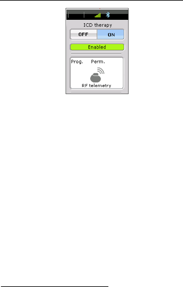
Lumax Technical Manual 71
The SafeSync symbol is displayed in the navigator and
the signal strength is displayed in green bars on the
information line. The SafeSync telemetry status is shown
in five increments: 1 bar = 20% up to 5 bars = 100%. A
weak contact shows only one bar in green, whereas all
five bars are shown in green when there is optimal
contact. The bars are shown in gray if RF telemetry is
lost. The display should have at least three green bars.
Otherwise, it is recommended to reposition the
programmer until an adequate signal strength is
achieved.
Remove the programming head.
To restore the SafeSync Telemetry after an interruption
during follow-up or after a programmer restart: select
Special→Continue RF session on the start screen to
restore the most recent active session. This SafeSync
Telemetry session must not have been inactive for longer
than five minutes, since the device's SafeSync Telemetry
activity is automatically switched off after five minutes of
inactivity.
Note: If the SafeSync Telemetry session has been
inactive for more than 5 minutes, the programming
head must be reapplied to reinitialize the SafeSync
Telemetry.
To End SafeSync Telemetry contact:
To end the SafeSync Telemetry session:
End Follow-up session
To switch to telemetry via the programming head (PGH):
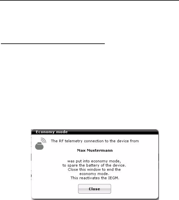
72 Lumax Technical Manual
Apply the programming head on the patient over the
device.
Select: More→Lumax→ Telemetry→PGH.
Power Consumption Consideration:
SafeSync telemetry requires somewhat more power than
telemetry via the programming head. Power consumption during
implantation corresponds to approximately 10 days of service
time and consumption during 20-minute follow-up corresponds to
approximately 3 days. As a result:
Do not establish SafeSync Telemetry sessions
unnecessarily.
After 5 minutes without input, SafeSync Telemetry
switches to the economy mode. In order to re-establish
telemetry from the economy mode, select “Close” in the
pop-up window with the patient’s name:
Check the battery capacity of the device at regular
intervals.

Lumax Technical Manual 73
2.2 Cardiac Resynchronization Therapy
(CRT)
HF versions only
For Cardiac Resynchronization Therapy (CRT), a sensing/pacing
lead is placed in the right atrium, while an ICD lead is placed in
the right ventricle. The third lead is positioned to pace the left
ventricle. When connected together, this system provides
coordinated, simultaneous stimulation of the right and left
ventricles. This resynchronization therapy is designed to
coordinate the contraction of both ventricles, which allows the
heart to contract more efficiently. As a result, patients with CHF
and intraventricular conduction delay may have a greater ability to
complete physical activities thus improving their quality of life.
As a result of the device design and header configuration,
ventricular pacing pulses can be delivered between the right/left
ventricular lead tip electrodes simultaneously (cathode) and at
programmed intervals. In some configurations the ring of the right
ventricular lead works as LV anode. Ventricular sensing primarily
uses the poles of the right ventricular lead tip and ring. This
design avoids sensing of ventricular activity twice during a single
cardiac cycle (double counting) in patients with a wide QRS
complex. However, for diagnostic purposes and LV pacing
protection the Lumax HF devices can be programmed to sense in
the left ventricle.
Atrial Channel
The Lumax ICDs/CRT-Ds pace and sense in bipolar
configuration, between the atrial lead’s tip and ring electrodes. A
bipolar atrial lead must be used to ensure reliable sensing of atrial
activity.
Ventricular Channel
The Lumax HF devices can be programmed to pace in both the
right and left ventricle (as well as RV only). The Lumax HF
primarily senses in a bipolar configuration in the right ventricle.
However, for diagnostic purposes and LV pacing protection the
Lumax HF devices can be programmed to sense in the left
ventricle.
Potential Ventricular lead configurations are provided in Table 26.
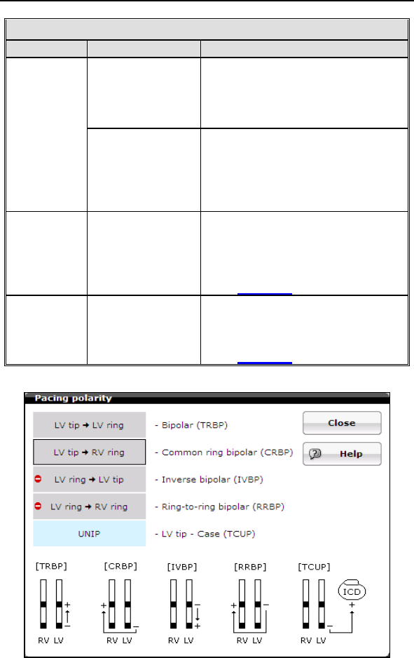
74 Lumax Technical Manual
Table 26. Lead Configurations
Configuration Explanation
RV Only Sensing takes place between
the tip and ring electrodes of
the right ventricular lead.
Sensing
LV Only Sensing takes place between
the tip and ring electrodes
(bipolar) or the tip electrode of
the left ventricular lead and the
CRT-D housing (unipolar).
Pacing RV & LV
Together (BiV)
Pacing configuration is
programmable between the tip
and ring electrodes of the right
and left ventricular leads.
See Figure 7
Pacing RV Only Pacing takes place between
the tip and ring electrodes of
the right ventricular lead.
See Figure 7
Figure 7 Programmable Pacing Configurations

Lumax Technical Manual 75
For CRT to be effective, ventricular pacing must occur. Therefore,
AV delays must be programmed short enough to override intrinsic
ventricular contractions. Additional information to further optimize
AV delays can be obtained with echocardiography.
CRT can be programmed ON or OFF via the programmer using
the [Ventricular Pacing] parameter. Ventricular Pacing
Configuration allows standard right ventricular [RV] (CRT = OFF)
pacing or Cardiac Resynchronization Therapy [BiV] (CRT = ON).
The Lumax HF CRT-D can provide triggered biventricular pacing.
This is a functional expansion of the basic ventricular modes
(DDD(R); DDI(R); VDI(R); VDD(R); VVI(R)) used for biventricular
pacing. The “RVs triggering” was designed to ensure CRT is
delivered even when rapid intrinsic activation interferes with
pacing, such as in the case of conducted atrial fibrillation. This
function triggers LV pacing (Vp) after intrinsic sensing (RVs) in
the right ventricle. Triggered pacing can be programmed to react
to only normal RV sensed events or to right ventricular
extrasystoles as well as normal RV sensed events. The maximum
trigger rate is normally limited by the programmed UTR
(+20bpm), but can also be programmed to function up to a
separate and higher maximum trigger rate.
V-V Delay Programming
V-V delays should be programmed based on optimization of the
echocardiographic parameter Aortic Valve Velocity Time Integral,
evaluating the full range of available delays, as was performed in
the clinical study demonstrating the safety and effectiveness of
this feature. RV pre-excitation may cause a decline of LV
function.
The V-V delay features for the Lumax HF-T devices include the
ability to program the following parameters “first chamber paced,”
which allows either the right or the left ventricle to be paced first,
and “VV delay” for setting a delay between the left and right
ventricular pacing pulses (programmable range: 0 ms … (5ms) …
100 ms).
Suggested optimization procedure:
During the V-V clinical study assessment was performed by
determining the V-V delay setting associated with the largest VTI
value. The VTI of the aortic flow is measured in the apical 5
chamber view.

76 Lumax Technical Manual
Prior to the V-V delay optimization procedure, each patient
underwent an optimization of AV timing. Following the AV timing
adjustment, this standardized procedure was followed for the
optimization of V-V delay:
1. Program the Lumax HF-T “Initially Paced Chamber”
parameter to either RV or LV based on preference
2. Assess the VTI measurement at the following V-V delays
(additional V-V settings may be utilized at the physician’s
discretion):
•100 ms
• 80 ms
• 60 ms
• 40 ms
• 20 ms
• 0 ms
Note: Use the average VTI parameter over a 3 beat cycle and
wait 10 to 15 seconds between changing V-V delay settings.
Also, attempt to measure the VTI parameter within the same
patient respiratory cycle.
3. Record the VTI measurement associated with each V-V
delay setting
Repeat steps 1-3 for the remaining “Initially Paced Chamber”
parameters
Select permanent “Initially Paced Chamber” and “V-V delay after
Vp” to reflect the maximum VTI measurement for final
programming.
2.3 Sensing (Automatic Sensitivity Control)
The Lumax ICDs/CRT-Ds use Automatic Sensitivity Control
(ASC) to adjust the input stage sensitivity threshold for each
channel to appropriately detect the various cardiac signals. The
characteristics of the sensing circuitry have been optimized to
ensure appropriate sensing during all potential cardiac rhythms.

Lumax Technical Manual 77
Cardiac signals vary in amplitude; therefore detection thresholds
cannot be static. With the Automatic Sensitivity Control (ASC)
every paced/sensed event is measured, and the upper and lower
thresholds are re-set accordingly (also known as beat-by-beat
adaptation). The ASC begins by tracking the cardiac signals (R
and P-waves) during the sensed refractory periods. The peak
values measured during this time are used to set the sensing
thresholds during the active detection periods.
2.3.1 Right Ventricular Sensitivity Settings
There are three programmable preset options for setting the
sensitivity of the right ventricular input stage. The sensitivity
selections are designed to adapt the parameters of the input
stage to various signal conditions. The predefined parameter sets
are described in Table 27.
Table 27: Sensitivity Settings
Setting Definition for Use
Standard This setting is recommended for most
patients, especially for those with
measured R-wave amplitude of 3 mV.
Enhanced
T Wave
Suppression
This setting offers suppression of T-wave
oversensing. This mode should not be
used on patients with the following
conditions:
Sinus rhythms with small signal
amplitudes, R-waves 4 mV
VF with highly fluctuating signal
amplitudes.
Enhanced
VF Sensitivity
This setting enhances VF detection, in
cases of highly fluctuating signal
amplitudes. It is not to be used for patients
that have sinus rhythms containing large
amplitude T-waves.
Typically, the upper threshold is reset with each sensed R-wave,
but in order to ensure that pacing does not occur during an
episode of VF, the ASC behaves differently with paced events.
Each paced event is followed by a paced refractory period after
which the ventricular threshold is set to the minimum
programmed value.
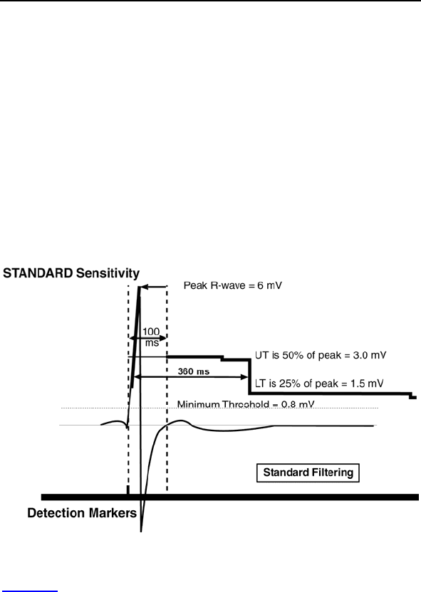
78 Lumax Technical Manual
For example, the upper threshold is set at 50% of the measured
R-wave for the Standard sensitivity setting following the 100 ms
sensed refractory period. The upper threshold decays 0.125 mV
every 250 ms through the T-wave discrimination period (hold of
upper threshold: 360 ms). After the T-wave discrimination period,
the threshold is decreased to the lower threshold. The lower
threshold is set to 25% of the measured peak R-wave. The lower
threshold then decreases 0.125 mV every 500 ms until the
Minimum Threshold is reached or until the next sensed (or paced)
event.
For Lumax 600/640 and 700/740 devices, the decrease is
controlled on a percentage basis. Every 156 ms 87.5% of the
threshold reference. Initially this is the maximum amplitude. Hold
of upper threshold: 400 ms.
Figure 8 Automatic Sensitivity Control with Standard Setting
Figure 8 provides an illustration of Automatic Sensitivity Control
with the sensitivity programmed to Standard. The tracked R –
wave is measured to be 6.0 mV, following the sensed refractory
period the upper threshold is set to 3.0 mV. After the T-wave
discrimination period, the threshold is further reduced to 1.5 mV.
Both the Upper and Lower Thresholds decay over time, but the
Minimum Threshold is never violated. Nominally, the minimum
threshold is set to 0.8 mV, but it can be adjusted by the user.

Lumax Technical Manual 79
The Enhanced VF Sensitivity setting is specifically designed to
improve VF detection when the VF signal is very small. Two
adjustments are made to ASC with this setting:
The T-wave discrimination period (hold of upper
threshold) is decreased to 100 ms [110 ms for Lumax
600/640 and 700/740 models], thus eliminating the Upper
Threshold.
The decay rate of the Lower Threshold is increased to
0.125 mV every 250 ms. This is not applicable for the
Lumax 600/640 and 700/740 models.
These adjustments ensure that the threshold reaches the lower
values more quickly in order to assure that all VF signals are
sensed appropriately.
The Enhanced T-Wave Suppression setting is specifically
designed to avoid double counting of each QRS-T complexes
during normal sinus rhythms. With sensitivity programmed to
Enhanced T-Wave Suppression:
High pass filtering is increased to reduce low frequency
signal components such as T-waves and respiratory
artifacts.
The Upper Threshold is increased to 75% of the
measured R-wave.
The Upper Threshold may not retrigger with each sensed
event, it is only triggered when the new sensed R-wave
crosses the 50% point of the previous measured R-wave.
2.3.2 Minimum Right Ventricular Threshold
This parameter limits the minimum sensitivity of the ICD/CRT-D to
a programmable value. Nominally, the minimum threshold is set
to 0.8 mV, but it can be adjusted from 0.5 to 2.5 mV.
2.3.3 Atrial Sensitivity Settings
DR and HF versions only
The primary option for setting the sensitivity of the atrial input
stage is “Standard”. When atrial sensing is active, the sensitivity
is set to “Standard” for most patients, which is designed to adapt
the parameters of the input stage to various signal conditions.
The available settings are described in Table 28.

80 Lumax Technical Manual
Table 28: Atrial Sensitivity Settings
Setting Definition for Use
Standard This setting is recommended for all
patients with a functioning atrial lead.
Inactive This setting deactivates the atrial channel
for sensing, EGM telemetry and Holter
recording and is typically used when no
atrial lead is implanted.
Typically, the upper threshold is reset with each sensed P-wave,
but in order to ensure that pacing does not occur during an
episode of AF/VF, the ASC behaves differently with paced
events. Each paced event is followed by a paced refractory
period after which the atrial threshold is set to the minimum
programmed value.
2.3.4 Minimum Atrial Threshold
This parameter limits the minimum sensitivity of the ICD/CRT-D to
a programmable value. Nominally, the minimum threshold is set
to 0.4 mV, but it can be adjusted from 0.2 to 2.0 mV.
2.3.5 Left Ventricular Sensitivity Settings
HF versions only
The primary option for setting the sensitivity of the left ventricular
input stage is “Standard”. When LV sensing is active, the
sensitivity is set to “Standard” for most patients, which is designed
to adapt the parameters of the input stage to various signal
conditions. The available settings are described in Table 29.

Lumax Technical Manual 81
Table 29: Left Ventricular Sensitivity Settings
Setting Definition for Use
Standard This setting is recommended for all
patients with a functioning left ventricular
lead.
Inactive This setting deactivates the left ventricular
channel for sensing, EGM telemetry and
Holter recording and is typically used when
no LV lead is implanted.
2.3.6 Minimum Left Ventricular Threshold
This parameter limits the minimum sensitivity of the CRT-D to a
programmable value. Nominally, the minimum threshold is set to
0.8 mV, but it can be adjusted from 0.5 to 5.0 mV.
2.3.7 Far Field Protection
DR and HF versions only
This parameter blanks the atrial channel of the ICD/CRT-D to the
period before and after each ventricular event. This blanking
period is programmable separately based on whether the
ventricular event is a paced or sensed event and is designed to
prevent sensing of ventricular signals with the atrial leads.
CAUTION
Far-field sensing of signals from the atrium in the
ventricular channel or ventricular signals in the atrial channel
should be avoided by appropriate lead placement,
programming of pacing/sensing parameters, and maximum
sensitivity settings. If it is necessary to modify the Far Field
Blanking parameter, the parameter should be lengthened
only long enough to eliminate far-field sensing as evidenced
on the IEGMs. Extending the parameter unnecessarily may
cause undersensing of actual atrial or ventricular events.
2.3.8 Additional Sensing Parameters
The parameters of the Additional Sensing Parameters menu are
to provide additional flexibility for physicians to non-invasively
correct over/undersensing situations. The ranges and nominal
values are located in the Technical Specifications in Section 6.

82 Lumax Technical Manual
Upper Threshold (A, RV & LV) - This feature allows the user to
change the upper sensing threshold level (UT in Figure 8) from
the nominal value of 50% of the sensed R-wave/P-wave
amplitude to either 75% or 87.5% of the R-wave/P-wave value.
This feature is used in the ventricle for example to eliminate
oversensing of large T-waves. This is not applicable to the Lumax
600/640 and 700/740 models.
Hold of Upper Threshold (RV & LV) - This parameter
determines when the sensing decrement begins after an event
(small step-down on the 50% threshold before LT in the figure
above). This parameter “holds” the threshold at a constant value
(UT in Figure 8) for the programmed time. Maximum Hold Time is
programmable from 100 to 600 ms in Lumax 300/340 & 500/540
and 110 to 500 ms in the Lumax 600/640 & 700/740 models (T-
Wave discrimination period). Additionally, the Lumax 600/640 &
700/740 models are separately programmable between the
paced and sensed signals.
Lower Threshold (A, RV & LV)- This feature allows the user to
change the lower sensing threshold (labeled LT in Figure 8) from
the default value of 25% of the sensed R-wave/P-wave amplitude
to either 12.5 or 50% of the measured R-wave/P-wave value. This
is not applicable to the Lumax 600/640 and 700/740 models. This
feature is also used in the ventricles to alleviate T-wave
oversensing and/or undersensing of small amplitude events (e.g.,
fine VF).
Blank after atrial pacing (RV) - This feature is used to eliminate
sensing of artifacts after atrial paced events. Blank Post atrial
Pace in the RV is programmable from 50 to 100 ms. For the left
ventricle, this parameter is equal to the safety window time
(100 ms).
VES Discrimination after As - This feature is used to correctly
identify and classify ventricular extrasystoles (VES). With each
atrial sensed event (also with Ars falling into PVARP) a special
timing interval is started for the ventricle, if the subsequent
ventricular event does not fall within the AV delay or the
programmed VES discrimination interval, it is classified as a VES.
LV T-wave Protection - Used to eliminate unintended pacing in
the vulnerable period of the left ventricle. This feature is only used
when left ventricular sensing is active. HF versions only.

Lumax Technical Manual 83
2.4 Automatic Threshold Measurement
(ATM)
Lumax 500/540 Models only
The Lumax 500/540 models have an automatic threshold
measurement (ATM) feature for determining ventricular pacing
thresholds. This feature is separately programmable for the right
(RV) and left (LV) ventricles.
ATM is initiated once each day, typically during the nighttime
while the patient is normally sleeping. It can measure the right
and the left ventricular pacing thresholds and stores this
information for use in trends of daily threshold values. This
information is available on the programmer during in-office follow-
ups and via BIOTRONIK’s Home Monitoring system. The
permanent pacing amplitude is not adjusted by the ATM feature.
The ATM features of Lumax 500/540 are based on the evaluation
of the morphology of the ventricular evoked response (VER) to
determine if the pacing pulse has captured the myocardium. In
order to measure the pacing threshold, a sequence of two
algorithmic steps is carried out:
Signal Quality Check (SQC)
Threshold Measurement
The signal quality check determines if the morphology of the
evoked response of a captured beat is sufficiently different from
the morphology of the evoked response of a non-captured pace.
If the SQC is sufficient (i.e., if the algorithm can clearly distinguish
between capture and non-capture), then the automatic threshold
measurement is activated by initiating a series of pacing pulses.
The amplitude of these pulses is continuously decreased until a
loss of capture is detected. When loss of capture is detected a
back-up pulse is delivered (right ventricle only) to avoid
ventricular pauses caused by the threshold measurement.

84 Lumax Technical Manual
2.4.1 Signal Quality Check
During the Signal Quality Check, five single effective pacing
pulses are delivered. These pulses are followed by five double
pulses. The second pulse of each double pulse is delivered into
the refractory phase of the ventricle (as a non-capturing pulse).
The VER morphology of the single pulses and the second pulse
of the double pulses are assessed. The signal quality check is
successful if the single pulses are recognized as capturing pulses
and the second pulses of the double pulses are classified as non-
capturing pulses. The AV delay of the 2 x 5 pulses is shortened to
50 ms after pace and by 15 ms after sense, in order to avoid
ventricular fusion beats which would otherwise disturb the SQC. If
the SQC is successful, then the threshold measurement is
started, if not, the SQC is repeated once again after 30 minutes.
2.4.2 Threshold Measurement
The threshold measurement begins by delivering pulses at the
programmed pacing amplitude. The pulse amplitude is decreased
in steps of 0.6 Volts (V) each until loss of capture is detected.
During the loss of RV-capture sequence, a backup pulse is
issued. The back-up is set to a value of the programmed pacing
amplitude plus 0.6 V with a pulse width of 1.0 ms. There are no
backup paces for left ventricular ATM (LV-ATM).
The pulse amplitude is then set to the last effective value (0.6
Volts above the initial non-capture level) and then subsequent
pacing pulses are reduced in 0.1 V steps until loss of capture
reoccurs. The last effective pacing amplitude is then recorded as
the pacing threshold.
2.4.3 Loss of Capture Detection
In order to ensure against ATM loss of capture detection due to
an isolated non-capture event (i.e. as a result of VES), loss of
capture is only declared if two out of three consecutive cycles
show loss of capture.
2.4.4 ATM in Lumax HF-T Models
If the device is programmed to biventricular pacing (BiV), the RV
ATM functions in the RV mode as described above. The LV ATM,
if active, is initiated after the RV ATM is complete. For the LV
ATM, the left ventricle is stimulated first with a VV delay of 50 ms
and then completed in a similar manner.

Lumax Technical Manual 85
Lumax 600/640 & 700/740 Models only
2.4.5 RV & LV Capture Control
RV & LV Capture Control uses the determined pacing threshold
to adjust the permanent pulse amplitude. The new permanent
pulse amplitude is composed of the determined pacing threshold
plus a safety margin (1.0 or 1.2 V) and is automatically
programmed in the ICD.
2.5 Ventricular Tachyarrhythmia Detection
The Lumax ICDs/CRT-Ds detect and measure the rate of sensed
cardiac signals to discriminate ventricular tachyarrhythmias from
supraventricular tachycardias, sinus rhythm or sinus bradycardia.
This is accomplished through programmable rate detection
parameters in the device. When a tachyarrhythmia is present, the
ICD/CRT-D classifies the arrhythmia and delivers the appropriate
therapy. If a tachyarrhythmia continues following the first therapy
attempt, then the ICD/CRT-D will redetect the tachyarrhythmia
and deliver subsequent therapies as necessary.
WARNING
Unwanted Shocks – Always program ICD therapy to OFF
prior to handling the device to prevent the delivery of serious
shocks to the patient or the person handling the device
during the implant procedure.
Classification of cardiac signals is accomplished primarily by
measuring the cardiac cycle length (R-R, P-R and P-P). In
addition, the ICD/CRT-D can also utilize abrupt changes in rate or
irregularity of the cardiac signal to further differentiate ventricular
tachyarrhythmias. Each detected ventricular tachyarrhythmia is
classified into one of the following zones:
VT-1 Lower rate ventricular tachycardia
VT-2 Higher rate ventricular tachycardia
VF Ventricular fibrillation
Each rhythm class is programmable to a separate rate with the
zone limit defining the lowest rate in each class. The upper rate
limit of each class is equal to the zone limit of the next higher
class, creating a continuous range of rate classes.

86 Lumax Technical Manual
2.5.1 VF Classifications
Detection of ventricular fibrillation (VF) utilizes programmable X
out of Y criterion. For the Lumax 300/340 & 500/540 models, both
X and Y are programmable. For the Lumax 600/640 and 700/740
models there are fixed combinations of X out of Y criterion. If X
number of intervals within the sliding window (defined by Y) are
shorter than the programmed VF rate interval (>bpm), VF is
detected. After fibrillation is detected, the programmed therapy
sequence for VF is initiated.
Nominal settings for classification of ventricular fibrillation (VF)
are 8 of 12 intervals; meaning that within a sample window of
12 intervals, 8 intervals must meet or exceed the VF zone rate
criteria.
2.5.2 VT Interval Counters
The VT Interval Counters are separately programmable for VT-1
and VT-2 rate classifications. The Counter: Detection is the
number of intervals required to declare a tachyarrhythmia as VT.
A tachyarrhythmia must meet the rate/interval criteria and the
programmed Counter/Detection criteria, in addition to any other
detection enhancements to be declared a tachycardia.
2.5.3 VT Classification
Both VT-1 and VT-2 classification zones utilize separately
programmable detection parameters. Classification of VT-1 or
VT-2 is based on the last interval average preceding declaration
of tachyarrhythmia detection. If this average falls within the VT-1
zone, the programmed VT-1 therapy is delivered. If the average
falls within the VT-2 limits, the programmed VT-2 therapy is
delivered. If additional detection parameters are activated, each
of these supplemental criteria must also be satisfied before a VT
rhythm can be classified and treated.

Lumax Technical Manual 87
The ICDs/CRT-Ds may be programmed to use ventricular-only
information, or both atrial and ventricular information for the
discrimination of ventricular tachyarrhythmias. With SMART
Detection™ turned ON, the Lumax ICDs/CRT-Ds use atrial and
ventricular signals for discrimination of fast heart rhythms. With
SMART Detection™ turned OFF, only the ventricular rate is used
to discriminate between ventricular rhythm classes. If SMART
Detection is enabled, this algorithm evaluates all cardiac signals
within the VT range and increments the VT Sample Count for all
intervals that are deemed VT. A full description of SMART
Detection™ is provided in Section 2.5.4.
In addition, when the Lumax senses the programmed number of
consecutive intervals (termination count) within the sinus rate
zone, all tachyarrhythmia detection criteria, including the VT
sample counters are reset.
2.5.4 SMART Detection™
DR and HF versions only
This discrimination algorithm enhances VT-1 and VT-2 detection
by applying a series of tests to the sensed cardiac signal. SMART
Detection™ is intended to discriminate VT from a variety of
supraventricular arrhythmias that are conducted to the ventricle
and that would otherwise satisfy VT-1 or VT-2 rate detection
criteria.
First, the average ventricular rate is compared to the average
atrial rate. In the event that the measured ventricular rate is faster
than the atrial rate, the device immediately declares the rhythm a
VT and delivers programmed ventricular therapy for the detected
VT zone.
In the event that an atrial rate is faster compared to the ventricular
rate one of three tests are performed:
Ventricular rhythm stability, (see Stability in Section 2.5.6 if the
ventricular signal is unstable, then the rhythm is declared a
supraventricular tachyarrhythmia, (SVT) and ventricular therapy is
typically withheld.
If the ventricular signal is stable, and the atrial rate is a multiple of
the ventricle rate, then the rhythm is declared a supraventricular
tachyarrhythmia (SVT) and ventricular therapy is typically
withheld.

88 Lumax Technical Manual
If the ventricular rhythm is stable and the atrial rate is not a
multiple of the ventricular rate, then the rhythm is declared a VT
and ventricular tachycardia therapy is delivered.
In the event that both the atrial and ventricular signals are
detected at the same rate, a series of additional discrimination
tests are applied.
2.5.5 Onset
Another detection enhancement that may be used independently
(VT-1 or VT-2, when SMART Detection is active) or as an adjunct
to the SMART Detection™ algorithm is the Onset parameter.
This parameter measures abrupt changes in ventricular cycle
length to discriminate between sinus tachycardias and ventricular
and atrial tachyarrhythmias, which characteristically begin with an
abrupt change in cardiac rate.
This feature allows therapy to be withheld if a sinus tachycardia
rate crosses into one of the VT zones.
2.5.6 Stability
In VT-1 and VT-2 zones, the purpose of STABILITY is to assist in
discriminating between stable ventricular tachyarrhythmias and
supraventricular tachyarrhythmias that conduct irregularly to the
ventricles. STABILITY evaluates sudden changes in the
regularity of cardiac events (R-R and P-P intervals) on a beat by
beat basis. The STABILITY criterion compares the current
measured interval with the three preceding cardiac intervals. If a
difference between the current interval and each of the three
preceding intervals is less than the stability range, then the
current intervals are stable.
The SMART Detection™ algorithm utilizes both atrial and
ventricular STABILITY as integral parts of the discrimination
algorithm. Therefore, when SMART Detection™ is enabled, the
STABILITY parameter must also remain enabled and set to 12%.
2.5.7 Sustained VT Timer
The Sustained VT Timer can be programmed between
30 seconds and 30 minutes (or to OFF) for the Lumax 300/340 &
500/540 models and 1 min to 30 minutes (or to OFF) in the
Lumax 600/640 and 700/740 models. When the timer expires,
therapy is initiated regardless of the detection enhancements.

Lumax Technical Manual 89
The Sustained VT parameter is intended to force tachycardia
therapy in cases where a cardiac rhythm meets the VT rate
criteria but does not satisfy one or more detection enhancement
criterion (Onset, SMART Detection, or Stability) for an extended
duration. This “safety” timer is initiated within one of the VT
zones. If the programmed Sustained VT time period expires
without tachycardia detection, redetection is initiated without
utilizing the detection enhancements.
A simple up/down counter is used to initiate the safety timer. The
counter is incremented by one when an interval falls into a VT
zone and decrements by one when an interval falls into the sinus
zone. When the counter reaches a number equal to the
programmed VT detection counter, the safety timer is started.
The timer runs until the programmed time expires and therapy is
delivered or until the timer is reset. The timer is reset with initial
detection or VT termination.
The safety timer is not used in redetection. If initial detection was
due to the safety timeout and SMART Redetection is
programmed “ON”, then SMART Detection will not be used for
redetection.
2.5.8 VT Monitoring Zone
The VT1 zone can be programmed to monitor for non-sustained
arrhythmias not requiring therapy. The monitoring zone can be
programmed with all the standard detection enhancements
including SMART DetectionTM to monitor for non-sustained
ventricular tachycardia or atrial tachyarrhythmias. Any
tachyarrhythmia meeting the Monitor Zone criteria will store an
IEGM.
2.5.9 Atrial Monitoring Zone
This feature allows the device to store an IEGM for atrial
tachyarrhythmias such as Atrial Fibrillation or Atrial Flutter. The
zone is programmed by rate with a range of 100 bpm to 250 bpm.
Any atrial tachyarrhythmia meeting the Atrial Arrhythmia Monitor
Zone criteria will store an IEGM.

90 Lumax Technical Manual
2.6 Tachyarrhythmia Redetection
The Lumax ICDs/CRT-Ds offer independently programmable
settings for determining if tachyarrhythmias remain after therapy
has been delivered. The redetection routine allows the
ICDs/CRT-Ds to determine whether further therapy is required
when the initial therapy was unsuccessful in terminating the
arrhythmia.
Tachyarrhythmia redetection criteria are based on cardiac cycle
length and number of intervals. The number of intervals is distinct
and independent of the initial detection criteria.
2.6.1 VT Redetection
The Counter: Redetection parameter may be programmed
separately for each arrhythmia class, independent of the initial
detection parameters:
Redetection of an ongoing tachyarrhythmia is declared when the
Counter: Redetection is satisfied (based on individual cycles). If a
sensed cardiac signal meets any VT rate criteria, following
therapy, that signal is counted and compared to the programmed
Counter: Redetection setting.
Redetection functions are based exclusively on the VT criterion.
2.6.2 SMART Redetection
DR and HF versions only
With SMART Redetection programmed ON, both atrial and
ventricular signals are used for redetection after initial detection
and therapy for a VT. SMART Detection™ will function identically
as in initial VT detection. SMART Redetection is autotmatically
programmed ON in the Lumax 600/640 and 700/740 models.
2.6.3 Forced Termination
DR and HF versions only
With SMART Redetection programmed ON, this programmed
parameter sets a time after which the SMART Redetection will be
terminated even if the SVT is still ongoing. This forces the device
to terminate the episode and allow detection of a new VT or VF
episode.

Lumax Technical Manual 91
2.6.4 VF Redetection
VF redetection uses the same X in Y algorithm as initial detection.
The X and Y values for initial detection are also used for
redetection to ensure consistent classification of VF.
2.7 Tachyarrhythmia Termination
Termination of a ventricular tachyarrhythmia episode is declared
when 12 out of 16 consecutive sensed intervals are longer than
the VT-interval parameter of the lowest VT class (sinus or
bradycardia rhythm).
2.8 Tachyarrhythmia Therapy
The Lumax ICDs/CRT-Ds offer a variety of therapy options that
can be tailored to meet a patient’s specific anti-tachycardia or
defibrillation therapy requirements. Anti-tachycardia pacing (ATP)
therapies can be combined with defibrillation therapies to provide
a broad spectrum of tachyarrhythmia treatment options.
2.8.1 Therapy Options
The Lumax ICDs/CRT-Ds offer multiple therapy options for each
tachyarrhythmia class (VT1, VT2, VF). Therapy options (up to 20
ATP sequences and 8 shocks) are available for the VT1 and VT2
zones, whereas ATP One Shot and up to 8 shock therapies are
available for the VF class. The specific characteristics of an ATP
and shock therapy are independently programmed for each
VT/VF zone.
The ATP and shock therapy options are discussed in detail in the
following sections.
2.8.2 Anti-Tachycardia Pacing (ATP)
Anti-tachycardia pacing therapy (ATP) is available in both VT
detection zones. Available modes of ATP include Burst, Ramp,
and Burst + PES (Programmed Extra Stimuli). However, in the
Lumax 600/640 and 700/740 models, Burst + PES is only
available at DFT test for EP examinations. In addition, the Burst
and Ramp modes allow interval scanning of the R-S1 Interval,
the S1 Decrement, or both. The Attempts parameter determines
the number of burst schemes to be delivered before the scan
parameter is incremented.

92 Lumax Technical Manual
Burst – This mode will deliver a series of pacing stimuli with user
defined duration of the burst (Number S1), coupling cycle length
(R-S1) and burst rate (S1-S1). The coupling interval and the start
interval are calculated from the intrinsic R-R average.
Ramp - This mode will deliver a series of pacing stimuli with the
above options including a parameter which decrements each
successive stimuli interval in the burst.
Burst + PES – In the Lumax 300/340 & 500/540 models, this
mode provides a pulse train followed by one additional timed
stimuli. The coupling cycle length of the burst and each extra
stimulus (S1-S2 Interval) is individually programmed either as an
adaptive value (as a percentage) or as an absolute value
(expressed in milliseconds). In the Lumax 600/640 & 700/740
models, Burst + PES is only available at DFT test for EP
examinations.
Ventricular Pacing - This parameter defines the type of
ventricular pacing performed during delivery of ATP sequences in
CRT-Ds and is programmable to biventricular (VV delay = 0 ms)
or right ventricular only.
Number S1 - This parameter defines the number of stimuli for an
ATP. For Burst + PES, a single extra stimulus with a separate
parameter setting is coupled. In the Lumax 600/640 & 700/740
models, Burst + PES is only available at DFT test for EP
examinations.
Add S1 - This feature can be programmed with any Burst, Ramp,
or Burst + PES (Lumax 300/340 & 500/540 models only) scheme.
When “Add S1” is “ON,” the number of S1 intervals is
incremented by one on each successive ATP therapy. The next
S1-S1 interval is dependent on the initial start interval (S1
decrement) and the programmed Scan Decrement (if activated).
R-S1 Interval - The R-S1 programmable coupling interval occurs
at the beginning of each ATP. It defines the interval between the
last R-wave signal and the first stimulus (S1). The second
stimulus always follows the first one with the same interval.
S1 Decrement - The S1 decrement continuously reduces the
pulse intervals of the ATP from the second pulse onward.

Lumax Technical Manual 93
S1-S2 Interval - The S1-S2 programmable coupling interval
occurs between the Burst sequence and the extra stimuli (PES). It
defines the interval between the first stimulus (S1) and the extra
stimuli (S2).
Scan Decrement - The Scan decrement continuously reduces
the starting pulse intervals of each Burst or Scan.
Minimum ATP Interval – For the Lumax 300/340 & 500/540
models, the programmed minimum interval prevents ATPs from
being given with stimulation values less than the minimum
interval. When the ATP interval reaches the value of the minimum
interval with the S1 decrement or scan decrement, it then
assumes this value and remains constant. For the Lumax
600/640 & 700/740 models, the minimum ATP interval is 200 ms
fixed.
2.8.2.1 ATP Help
ATP help is a useful tool to assist the physician in choosing and
confirming appropriate ATP programming. The “ATP Help” button
is displayed in each ATP therapy option. When the ATP help
button is pressed, a histogram of the chosen therapy scheme is
shown. The histogram displays the intervals for the programmed
ATP scheme. When rate adaptive intervals are programmed, the
displayed intervals are based on the programmed R-R average.
2.8.2.2 ATP Optimization
In order to optimize future therapies, the ICD will store the
parameter configuration of the last successful ATP attempt in
each the VT1 and VT2 classes. The last successful stored ATP
attempt is then used as the starting point for the next detected
episode of the same arrhythmia class. If the stored parameter
configuration is not successful, it is deleted from the ATP
optimization memory of the respective arrhythmia class and
subsequent therapy sequences will begin with ATP1 for the next
detected episode.
ATP Optimization is programmable ON or OFF for all ATP
therapies and VT zones with one parameter.

94 Lumax Technical Manual
NOTE:
In VT zones, the ICD/CRT-D stores successful ATP therapies
only. The stored information includes not only the number of
the ATP therapy (e.g., ATP2), but also the successful
configuration in detail (for example: Burst; R-S1 Interval:
320 ms, S1-S1 Interval: 320 ms; etc.).
2.8.2.3 ATP Timeout
ATP Timeout is a timer that decrements after the initial ventricular
ATP is delivered (VT-1 zone) and limits the additional ATP
therapies that may be delivered. Once the timer expires, all
further ATP therapies in the sequence are blocked. If further
therapy is required after the timer has expired, the system
advances to the first programmed shock therapy for the
applicable VT zone. Therapy continues until arrhythmia
termination or all programmed therapy (in the applicable zone)
has been delivered. The ATP Timeout is reset each time an
arrhythmia is terminated.
Note: ATP Timeout is not applicable in the Lumax 600/640 &
700/740 models since the Progressive Course of Therapy is
automatically programmed in these devices.
2.8.2.4 ATP One Shot
ATP One Shot offers the opportunity to treat fast VTs that are
detected in the VF zone with a single ATP sequence delivered
immediately before charging of the high energy capacitors. The
device performs a stability check (same as VT zones, criterion
12% fixed) to determine if the arrhythmia might be a fast VT and if
the rhythm is stable, the programmed ATP sequence is delivered
prior to charging. Charging starts without redetection and the
successful treatment of the arrhythmia will be confirmed prior to
shock delivery during shock charging. If the arrhythmia is
converted by the ATP, the shock is aborted. All ATP therapy
parameters are available for programming ATP One Shot and it
can only be used with Shock Therapy programmed ON.

Lumax Technical Manual 95
2.8.3 Shock Therapy
Shock Therapy is developed by internal circuitry that stores
energy across high energy capacitors. The voltage level for the
charging cycle is based on the programmed energy level. The
energy is then delivered over the connected ICD lead and
through the ICD/CRT-D housing utilizing a biphasic waveform.
The first and second shock energies in each shock module have
independently programmable Shock Energy.
A synchronization window is started at the end of the charging
period. During this window, the device will attempt to synchronize
the shock therapy to an R-wave. If no R-wave is detected and
Confirmation is programmed to OFF, the shock will be delivered
asynchronously at the end of the synchronization period (DF). If
no R-wave is detected and Confirmation is programmed to ON,
the shock will be aborted at the end of the synchronization period
(DFc = Cardio Version).
2.8.3.1 Confirmation
The Confirmation parameter is used to verify the presence of a
tachyarrhythmia during charging of the shock capacitors. This
function is designed to avoid delivery of shock therapy if a
tachyarrhythmia has spontaneously terminated. The programmed
shock will be delivered unless bradycardia or a normal sinus
rhythm is detected during the Confirmation period. Confirmation
may be programmed ON or OFF for each zone (VT-1, VT-2 or
VF). Although if a shock is aborted and redetection occurs (even
in a zone with confirmation programmed ON) the subsequent
shock will be delivered without confirmation (see confirmation
OFF).
Confirmation OFF
When Confirmation is programmed OFF, shock therapy will be
delivered to the patient during the synchronization period
regardless of the detected cardiac signal.
Confirmation ON
If the tachyarrhythmia spontaneously converts to bradycardia or a
normal sinus rhythm during the confirmation period, shock
therapy is aborted. If the device confirms the presence of the
tachyarrhythmia, the device will deliver the programmed shock
therapy synchronized to the R-wave.
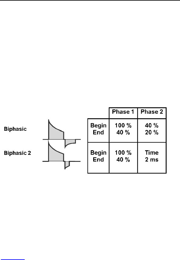
96 Lumax Technical Manual
2.8.3.2 Number of Shocks
The number of shocks defines the total number of shock attempts
per therapy zone (VT-1, VT-2 or VF). Up to 8 shocks are
available in each therapy zone. The first and second shock
energies are independently programmable, while the remaining
shocks are fixed at maximum energy (30 joules for
300/500/600/700 series devices and 40 joules for
340/540/640/740 series devices).
2.8.3.3 Shock Waveform
Two waveforms of shock therapy are available with the Lumax
ICDs/CRT-Ds, Biphasic and Biphasic 2 (ms). The following
diagram describes each of the shock waveforms.
Figure 9. Biphasic Waveforms
Both waveforms start at the calculated voltage, based on the
programmed energy level. After an exponential discharge through
the lead system to 40% of the initial charge voltage, both shock
waveforms switch polarity. At the second phase the:
Biphasic waveform discharges to 20% of the initial charge
voltage before the waveform is truncated
Biphasic 2ms waveform discharges the remaining energy
for two milliseconds before the waveform is truncated
Figure 9 provides a pictorial representation of both biphasic
waveforms.
BIOTRONIK recommends use of the standard Biphasic shock
waveform for initial defibrillation threshold testing. If testing
demonstrates high defibrillation thresholds, testing with the
Biphasic 2ms waveform is offered as a therapeutic alternative to
the standard Biphasic shock.

Lumax Technical Manual 97
2.8.3.4 Shock Energy
The Lumax ICDs/CRT-Ds are designed to charge to the energy
selected on the programmer screen, but similar to all other
commercially available ICDs/CRT-Ds, the actual therapy
delivered is somewhat less depending on several factors
including the shock lead impedance. The first two shock energies
in each therapy class are programmable between 1 joules for
Lumax 300/340 & 500/540 models and 2 joules for Lumax
600/640 & 700/740 models and the maximum energy for the
device type. The energy of the second shock is always greater
than the first shock. The remaining shock energies will be
delivered at maximum programmable energy.
Actual energy delivered for each programmable shock energy is
approximately equal to the “Energy Delivered” for the high energy
Lumax 340/540/640/740 variants in Table 30, and for the Lumax
300/500/600/700 in Table 31

98 Lumax Technical Manual
Table 30 Delivered Shock Energy (340/540/640/740
Variants)
Programmed Energy
(joules)
Approximate Delivered
Energy (joules)
1 0.8
2 1.7
3 2.6
4 3.5
5 4.3
6 5.2
7 6.1
8 6.9
9 7.8
10 8.7
11 9.6
12 10.5
13 11.3
14 12.2
15 13.1
16 13.9
18 15.7
20 17.3
22 19.1
24 21.1
26 22.8
28 24.4
30 26.3
32 27.9
34 29.7
36 31.5
38 33.3
40 35.0

Lumax Technical Manual 99
Table 31 Delivered Shock Energy (300/500/600/700
Variants)
Programmed Energy
(joules)
Approximate Delivered
Energy (joules)
1 0.8
2 1.7
3 2.5
4 3.3
5 4.3
6 5.1
7 6.0
8 7.0
9 7.8
10 8.6
11 9.6
12 10.6
13 11.4
14 12.3
15 13.1
16 14.2
18 16.0
20 17.7
22 19.5
24 21.4
26 23.2
28 24.9
30 27.0

100 Lumax Technical Manual
CAUTION
Shock Impedance - If the shock impedance is less than
twenty-five ohms (25 Ω), reposition the lead system to allow
a greater distance between the electrodes. Never implant the
device with a lead system that has measured shock
impedance as less than twenty-five ohms (25 Ω). Damage to
the device may result.
Defibrillation Threshold - Be aware that changes in the
patient’s condition, drug regimen, and other factors may
change the defibrillation threshold (DFT), which may result in
non-conversion of the arrhythmia post-operatively.
Successful conversion of ventricular fibrillation or ventricular
tachycardia during arrhythmia conversion testing is no
assurance that conversion will occur post-operatively.
Shock Therapy Confirmation – Programming
CONFIRMATION to OFF may increase the incidence of the
ICD/CRT-D delivering inappropriate shocks.
2.8.3.5 Shock Polarity
The polarity of the shock therapy may be programmed and
changed non-invasively. The Normal polarity configures the HV 1
or RV connector port as the negative electrode and the HV 2 or
SVC connector port and the outer housing of the ICD/CRT-D as
the positive electrode for the first phase of the shock. Reversed
polarity will switch the electrical polarity of the connector ports
and housing. The shock polarity is separately programmable for
each arrhythmia zone.
Alternating polarity is automatically employed when a maximum
energy shock with normal polarity fails to cardiovert. The next
shock will have reversed polarity and alternates the polarity for all
subsequent shocks.
Lumax Technical Manual 101
2.8.3.6 Third Programmable Shock Pathway
Lumax 500/540, 600/640 & 700/740 Models only
The Lumax 500/540, 600/640 and 700/740 models offer three
programmable shock delivery configurations. The defibrillation
shock pathways include a “non-active housing” shock path and a
shock paths between the ICD/CRT-D housing and either or both
shock coils when connected to a dual coil shock lead.
The Shock Configuration parameter operates independently of
Shock Polarity. So each of the pathways described below can be
reversed for delivered defibrillation/cardioversion shocks.
Table 32 outlines the current shock pathways that are available
with Lumax 500/540, 600/640 and 700/740 models.
Table 32 Lumax 500/540, 600/640 & 700/740
Programmable Shock Pathways
# Electrical Pathway
1) RV SVC and Housing (can)*
2) RV SVC
3) RV Housing (can)
* 300/340 Models are limited to this configuration.
2.8.4 Progressive Course of Therapy
By design, the Lumax ICDs/CRT-Ds will deliver more aggressive
therapy for each successive attempt within a single detected
episode. Therefore, the device will not deliver ATP1 therapy
following ATP2 therapy, and will not deliver ATP therapy following
a high voltage defibrillation shock.
When Progressive Course of Therapy is turned ON (this is
automatically programmed ON in the Lumax 600/640 & 700/740
models), the ICD/CRT-D will always deliver a maximum energy
shock after re-detecting in an arrhythmia class with programmed
shock energy less than or equal to the previously delivered
therapy. In addition, the ICD/CRT-D blocks all ATP therapy during
the current episode if a shock has already been delivered during
the episode.

102 Lumax Technical Manual
Furthermore, the ICD/CRT-D prevents therapies of different
arrhythmia classes from permanently retarding or accelerating a
VT in such a way that the cardiac rhythm fluctuates between the
different arrhythmia classes without achieving termination of the
arrhythmia, regardless of the Progressive Course of Therapy
setting.
For example, a 10-joule defibrillation shock is delivered for an
arrhythmia detected in the VT-2 zone and results in a
deceleration of the VT so that it is subsequently redetected in the
VT-1 zone. At that point, the Lumax ICDs/CRT-Ds would continue
with shock therapy, but all shocks programmed at less than 10
joules would be delivered at 10 joules.
If a defibrillation shock is delivered but does not terminate the
arrhythmia, the next shock will always have the same or higher
energy than the last delivered shock. Beginning with the third
shock, all shocks are delivered at maximum energy.
2.9 Bradycardia Therapy
The Lumax ICDs/CRT-Ds have independently programmable
single, dual and triple chamber and post-shock pacing functions.
The post-shock bradycardia parameters may be programmed to
higher rates or output values for the period following a delivered
shock, without significantly compromising the longevity of the
ICD/CRT-D for patients who require chronic bradycardia pacing.
The post-shock programmable values are presented in a
separate subsection from the normal bradycardia pacing support
values.
2.9.1 Bradycardia Pacing Modes
The available bradycardia pacing modes for each member of the
Lumax ICD/CRT-D family are listed in Table 33.
Table 33 Lumax Pacing Modes
Mode Lumax
HF(-T)
Lumax
DR(-T)
Lumax
VR(-T)
Lumax
VR-T DX
DDDR X X N/A N/A
DDIR X X N/A N/A
VDDR X X N/A X
VDIR X X N/A X
AAIR X X N/A N/A

Lumax Technical Manual 103
Table 33 Lumax Pacing Modes
Mode Lumax
HF(-T)
Lumax
DR(-T)
Lumax
VR(-T)
Lumax
VR-T DX
VVIR X X X X
DDD X X N/A N/A
DDI X X N/A N/A
VDD X X N/A X
VDI X X N/A X
AAI X X N/A N/A
VVI X X X X
V00 X X X X
D00 X X N/A N/A
OFF X X X X
The basic rate timer is started by a sensed or paced event. A
sensed event outside of the refractory period inhibits pacing and
resets the lower rate time; in the absence of a sensed event, a
pacing pulse will be delivered at the end of the lower rate interval.
The pacing modes with an “R” indicate rate adaptive pacing
controlled by a motion based capacitive sensor. These modes are
functionally the same as the corresponding non-rate-adaptive
modes, except that the pacing rate is increased based on
physical activity.
2.9.2 Basic Rate
The basic rate is the pacing rate in the absence of a patient’s
intrinsic rhythm. This rate may be independently programmed for
normal and post-shock bradycardia pacing.
2.9.3 Night Rate
The night rate is the effective basic rate during the programmed
“sleep” period for the patient. This parameter provides a different
pacing rate during the patient’s normal sleep time in an attempt to
match, for example, the decreased metabolic needs during sleep.
When Night Mode is active, the basic rate automatically changes
to the programmed NIGHT RATE during the nighttime hours.

104 Lumax Technical Manual
At the programmed start time (Begin of Night), the rate gradually
adapts to the night rate. When the internal clock reaches the
programmed end time (End of Night), the pacing rate gradually
changes to the programmed basic rate. The rate changes at the
same rate as the Sensor Gain decrease and increase
parameters.
NOTE:
The Night Mode time is based on the programmer clock.
Therefore, the programmer time should be checked prior to
device programming. If a patient travels across different time
zones, the Night Mode time may require adjustment.
2.9.4 Rate Hysteresis
The ability to decrease the effective lower rate through
Hysteresis is intended to preserve a spontaneous rhythm. The
pulse generator operates by waiting for a sensed event throughout
the effective lower rate interval (Hysteresis interval). If no sensed
event occurs, a pacing pulse is emitted following the Hysteresis
interval.
Hysteresis can be programmed OFF or to values as low as
-90 bpm in Lumax 300/340 & 500/540 models (-65 bpm in the
Lumax 600/640 & 700/740 models) of the basic rate. Hysteresis
is initiated by a sensed event. The resulting Hysteresis rate is
always less than the lower rate. The Hysteresis rate can only be
programmed to provide a basic rate that is 30 bpm or greater.
NOTES:
If rate adaptation is active, the Hysteresis rate is based on the
current sensor-indicated rate and the value of the
programmable parameter.
If Hysteresis is used in the DDI mode, the AV delay must be
programmed shorter than the spontaneous AV conduction
time. Otherwise, stimulation in the absence of spontaneous
activity occurs at the hysteresis rate instead of the lower rate.
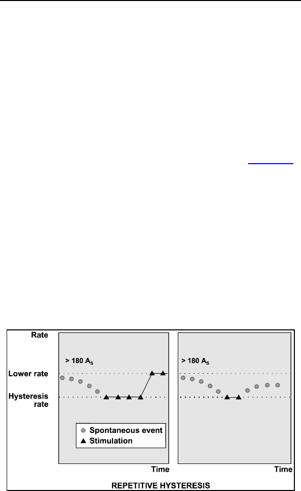
Lumax Technical Manual 105
Night Rate is the limit for the Hysteresis when Night Mode is
active. Programming conflicts arise when the total decrease
in rate is below 30 ppm. Care should be exercised to avoid
programming a Night Mode rate and hysteresis that are
below what is appropriate and may be tolerated by the
individual patient.
2.9.4.1 Repetitive Hysteresis
Repetitive hysteresis is expanded programmability of the
Hysteresis feature. Repetitive hysteresis searches for an intrinsic
cardiac rhythm, which may exist below the programmed lower
rate (or sensor-indicated rate) of the patient (see Figure 10).
Following 180 consecutive sensed events, this feature allows the
intrinsic rhythm to drop to or below the hysteresis rate. During the
time when the intrinsic rate is at or below the hysteresis rate,
pacing occurs at the hysteresis rate for the programmed number
of beats (up to 10) in the Lumax 300/340 & 500/540 models and
at 10 beats with scan hysteresis in the Lumax 600/640 & 700/740
models. Should the number of programmed beats be exceeded,
the stimulation rate returns to the lower rate (or sensor-indicated
rate).
If an intrinsic cardiac rhythm is detected within the programmed
number of beats between the hysteresis rate and the lower rate,
the intrinsic rhythm is allowed and inhibits the pulse generator.
Figure 10. Repetitive Hysteresis

106 Lumax Technical Manual
Repetitive hysteresis has been incorporated to promote
spontaneous cardiac rhythm and may reduce pulse generator
energy consumption.
NOTE:
Repetitive and Scan Hysteresis are only available when
Hysteresis is selected ON.
There is one Standard Hysteresis interval which occurs
before the programmable number of Repetitive Hysteresis.
2.9.4.2 Scan Hysteresis
Scan hysteresis is expanded programmability of the Hysteresis
feature. Scan hysteresis searches for an intrinsic cardiac rhythm,
which may exist just below the programmed lower rate (or
sensor-indicated rate). Following 180 consecutive paced events,
the stimulation rate is temporarily decreased to the hysteresis
rate for a programmed number of beats (see Figure 11) in the
Lumax 300/340 & 500/540 models and at 10 beats with scan
hysteresis in the Lumax 600/640 & 700/740 models. If a cardiac
rhythm is not detected within the programmed number of beats at
the hysteresis rate, the stimulation rate returns back to the
original lower rate (or sensor-indicated rate). Several
programmable beat intervals are available to allow a greater
probability of detecting a spontaneous rhythm.
If an intrinsic cardiac rhythm is detected within the programmed
number of beats between the hysteresis rate and the lower rate,
the intrinsic rhythm is allowed and the pulse generator inhibits.
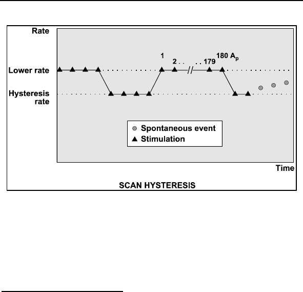
Lumax Technical Manual 107
Figure 11. Scan Hysteresis
Scan hysteresis has been incorporated to promote intrinsic
cardiac rhythm and may reduce pulse generator energy
consumption.
2.9.5 Dynamic AV Delay
DR and HF versions only
The AV Delay defines the interval between an atrial paced or
sensed event and the ventricular pacing pulse. If the pulse
generator is programmed to a dual chamber sensing mode, an
intrinsic ventricular event falling within the AV Delay will inhibit the
ventricular pacing pulse. If not contraindicated, a longer AV Delay
can be selected to preserve intrinsic AV conduction.
Dynamic AV Delay is where the AV Delay is varied depending on
the spontaneous atrial rate. Dynamic AV Delay provides a linear
change of AV Delays depending on current rate at preset lower
and upper AV Delay values.
In addition to selecting the preset values (Low, Medium, and
High) with the Dynamic AV Delay window, the Dynamic
AV Delays may be programmed individually (Individual) for each
rate zone or to a fixed AV Delay (Fixed).

108 Lumax Technical Manual
The AV Delay feature includes an AV Delay shortening option
(Sense Compensation) for dual chamber pacing modes. When
enabled, the AV Delay is shortened by the programmed value
(-5 to -60 ms in Lumax 300/340 & 500/540 models and up to
-120 ms in Lumax 600/640 & 700/740 models) from the
programmed AV Delay after an intrinsic atrial sensed event.
The Dynamic AV Delay is intended to mimic physiologic-
shortening of the AV Delay with increasing heart rate. It also
serves for automatic prevention and termination of “circus
movement” pacemaker mediated tachycardia and for prevention
of reentrant supraventricular tachycardias. Dynamic AV Delay is
available with the Lumax DR-T and HF-T ICDs/CRT-Ds.
2.9.5.1 Positive AV Hysteresis
Positive AV Hysteresis allows a user-programmable change in
AV delay that is designed to encourage normal conduction of
intrinsic signals from the atrium into the ventricles. With Positive
AV hysteresis enabled, the AV delay is extended by a defined
time value after sensing a ventricular event (10 … (10) …150 ms)
in the Lumax 300/340 & 500/540 models and (70, 110, 150, 200
ms) in the Lumax 600/640 & 700/740 models. The long AV
interval is used as long as intrinsic ventricular activity is detected.
The programmed short AV delay interval resumes after a
ventricular paced event.
2.9.5.2 AV Repetitive Hysteresis
With AV Repetitive Hysteresis, the AV delay is extended by a
defined hysteresis value after sensing an intrinsic ventricular
event. When a ventricular paced event occurs, a long AV delay is
used for the programmed number of cycles. (OFF, 1 … 10) in
Lumax 300/340 & 500/540 models and 5 fixed cycles with scan
AV hysteresis in the Lumax 600/640 & 700/740 models. If an
intrinsic rhythm occurs during one of the repetitive cycles, the
long duration AV delay interval remains in effect. If an intrinsic
rhythm does not occur during the repetitive cycles, the original AV
delay interval resumes.

Lumax Technical Manual 109
2.9.5.3 AV Scan Hysteresis
With AV Scan Hysteresis enabled, after 180 consecutive pacing
cycles, the AV delay is extended for the programmed number of
pacing cycles. (OFF, 1 … 10) in Lumax 300/340 & 500/540
models and 5 fixed cycles with scan AV hysteresis in the Lumax
600/640 & 700/740 models. If an intrinsic rhythm is detected
within the extended AV delay, the longer AV delay remains in
effect. If an intrinsic rhythm is not detected within the number of
scan cycles, the original AV delay value resumes.
2.9.5.4 Negative AV Hysteresis
With Negative AV Hysteresis, the AV delay is decreased by a
programmable value (10 … (10) …150 ms) after a ventricular
event is sensed, thereby promoting ventricular pacing. The
shortened AV interval is used for one time.
2.9.5.5 Negative AV Repetitive Hysteresis
With AV Repetitive Hysteresis and negative AV Hysteresis, the
AV delay is shortened by a defined hysteresis value after sensing
an intrinsic ventricular event as described above. The short AV
Delay will remain until the programmed number of cycles has
elapsed. (OFF,1 … 180) in Lumax 300/340 & 500/540 models
and 180 fixed cycles in the Lumax 600/640 & 700/740 models.
The normal AV delay resumes after the programmed number of
consecutive ventricular paced events (Repetitive Negative AV
Hysteresis) elapses.
CAUTION
Negative AV Hysteresis – This feature insures ventricular
pacing, a technique which has been used in patients with
hypertrophic obstructive cardiomyopathy (HOCM) with normal
AV conduction, in order to replace intrinsic ventricular
activation. No clinical study was conducted to evaluate this
feature, and there is conflicting evidence regarding the
potential benefit of ventricular pacing therapy for HOCM
patients. In addition, there is evidence with other patient
groups to suggest that inhibiting the intrinsic ventricular
activation sequence by right ventricular pacing may impair
hemodynamic function and/or survival.
110 Lumax Technical Manual
2.9.6 IOPT
DR versions only
The IOPT function serves to support the patient’s intrinsic rhythm
and avoid excessive ventricular pacing. This feature simply
activates all of the AV hysteresis parameters with a single
selection. Table 34 details the settings that are preset when
IOPT is turned ON:
Table 34 IOPT Parameters
Parameter IOPT
AV Hysteresis (max AV Delay) 400 ms
AV Scan Hysteresis 5
Repetitive AV Hysteresis 5
2.9.7 Upper Tracking Rate
DR and HF versions only
In the atrial tracking modes (DDDR, VDDR, DDD, and VDD)
ventricular pacing tracks atrial pace/sense events. The maximum
tracking rate (ventricular pacing rate) is limited by the Upper Rate
parameter.
The UTR response will automatically toggle between 2:1 and
WKB (Wenckebach) depending on the relative programmed
values for upper rate and atrial refractory period (AV Delay +
PVARP).
If the UTR is less than the maximum sensed atrial rate, defined
by the atrial refractory period (60,000/ARP), the WKB response is
utilized. Atrial rates exceeding the selected upper rate will result
in a Wenckebach-type pacing pattern. This is accomplished by
progressively lengthening the AV delay to keep the ventricular
pacing rate at the upper rate. Lengthening of the AV interval is
interrupted as soon as: 1) a P-wave falls within the atrial blanking
period and is not detected; or 2) a succeeding P-wave is detected
before the end of the AV delay previously started. In the second
case, the corresponding ventricular pacing pulse is suppressed. If
the atrial rate is just above the upper rate, a low degree (i.e. 6:5)
block results. Higher atrial rates result in higher degrees of AV
block until the intrinsic atrial cycle length violates the programmed
atrial refractory period causing a 2:1 or greater block.

Lumax Technical Manual 111
The 2:1 response is utilized when the rate defined by the atrial
refractory period is less than the upper rate. In such a case, the
maximum pacing rate is regulated by the inability to respond to
P-waves falling within the atrial refractory period.
If the resulting length of the spontaneous atrial cycle is shorter
than the atrial refractory period in a rate-adaptive mode, the
resulting pacing rate will depend on whether the 2:1 rate has
been exceeded. If this is the case, the pulse generator will use
the sensor rate as the pacing rate. If the 2:1 rate is not exceeded,
the pulse generator will use a rate that lies between the sensor
rate and the rate determined by the atrial refractory period.
Atrial Upper Rate is designed to prevent pacing in the vulnerable
period after an atrial sensed event during PVARP. It ensures that
the next atrial pace is emitted outside of the patient’s normal
sinus atrial refractory period. Atrial Upper Rate is limited to
240 ppm or OFF in Lumax 300/340 & 500/540 models and OFF,
175, 200 or 240 ppm in the Lumax 600/640 & 700/740 models.
NOTE:
Lumax DR ICDs and Lumax HF CRT-Ds allow the UTR to be
programmed within the VT-1 zone. This feature is for patients
that are active and have exercise and VT rates that overlap.
This may be desirable in young active patients. Also, with
RVsense Triggering programming the UTR in the VT-1 zone
is blocked.
2.9.8 Mode Switching
DR and HF versions only
Mode switching is designed to avoid tracking of atrial arrhythmias.
In the presence of a high atrial rate, the bradycardia pacing mode
is automatically reprogrammed to a non-atrial tracking mode. The
modes available during mode switching are as shown in
Table 35. Mode switching is not available during the post-shock
pacing period. Mode Switching is only available with the Lumax
DR and Lumax HF ICDs/CRT-Ds.

112 Lumax Technical Manual
Table 35: Mode Switching Modes
Programmed Mode Converted Mode
DDDR DDIR
DDI
DDD DDIR
DDI
VDDR VDIR
VDI
VDD VDIR
VDI
Mode switching is initiated in atrial tracking modes when the atrial
rate, defined by the programmable mode switch Intervention
Rate is achieved. However, mode switching will not occur until
the Mode Switch Onset Criterion is also met. The activation
criterion is a programmable X out of 8 high rate intervals as
programmed. RVsense Triggering can be programmed
separately during mode switching.
After switching to a non-atrial tracking mode, the ICD/CRT-D
activates a Y out of 8 counter that deactivates mode switching
when Y number of cardiac cycles out of the last 8 are below the
Intervention Rate. When this Resolution Criterion parameter is
fulfilled, the ICD/CRT-D returns to the normal programmed pacing
mode.
In addition, the ventricular pacing configuration (RV or BiV) and
biventricular pacing parameters (LV T-wave protection and
Triggering) are programmable separately for mode switching
events.
2.9.8.1 Mode Switch Basic Rate
Whenever Mode Switching occurs, the device switches to a non-
tracking mode and will provide bradycardia pacing support at the
Mode Switch Basic Rate, which is displayed as the Change of
Basic Rate parameter. Once Mode Switching is terminated, the
permanently programmed pacing mode and programmed pacing
rate are restored.

Lumax Technical Manual 113
2.9.8.2 Post Mode Switch Response
Whenever Mode Switching event terminates, deactivating the
mode switch pacing, the device can be programmed to react with
a different basic rate for a specified amount of time. Two
parameters are used to set the Post Mode Switch Response.
Post ModeSw Rate sets the rate difference (from permanent
program) in pacing rate during the programmed Post ModeSw
Duration time period. After the Post ModeSw Duration expires,
the pacing rate is ramped down to the programmed basic rate.
2.9.9 PMT Management
A PMT is defined as a tachycardia caused by inadvertently
tracking retrograde P-waves. The PMT management feature
includes PMT Protection/Termination and a programmable PMT
detection and termination algorithm.
2.9.9.1 Protection
PMT protection is accomplished by the following mechanisms
(see Figure 12):
Upon detection of a ventricular extrasystole (VES), the
lower rate interval and the atrial refractory period (ARP)
are reset. Additionally, in VDD mode, the atrial refractory
period is initiated with a ventricular pacing pulse that has
not been triggered by atrial detection. This prevents a
retrograde P-wave with a VA conduction time shorter
than the ARP from being sensed and thus from triggering
a ventricular pacing pulse. This provides an automatic
PMT protection.
A programmable atrial refractory period extension
(ARPE) is available in the DDD and VDD modes. To
prevent the initiation of a pacemaker mediated
tachycardia (PMT) by a ventricular depolarization not
preceded by an atrial depolarization, the ARP will be
extended by the ARPE if the ARP was:
o started by a ventricular sense event outside of the AV
delay (e.g., PVC) in DDD and VDD or
o reset by a ventricular pulse not triggered by an atrial
sense event in VDD.
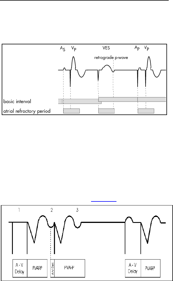
114 Lumax Technical Manual
In these instances, the ARP will usually be long enough to
prevent sensing of retrograde P-waves. Programming to an
ARPE other than 0 ms may rarely be required but could provide
additional protection if the ARP is limited or the retrograde
conduction time extended.
Figure 12. Prevention of PMT by VES starting ARP (DDD).
2.9.9.2 Termination
PMT termination can be accomplished by the following
mechanism:
The programmable dynamic AV delay in combination with a fixed
TARP (i.e. modulated PVARP) can act as a ‘passive’ termination
of a PMT. Because a PMT is generally at higher rates, the
AV delay will be relatively short. This causes the PVARP to be
prolonged, which then increases the chance that a retrograde
conducted atrial depolarization falls in the PVARP and thus will be
inhibited, terminating the PMT (see Figure 13).
Figure 13. Dynamic AV delay for PMT termination

Lumax Technical Manual 115
2.9.9.3 PMT Detection and Termination
In addition to PMT prevention, Lumax contains a programmable
PMT detection and termination algorithm. The termination feature
will take action in case the prevention was not effective and a
PMT is detected. The PMT detection constantly monitors for the
presence of a PMT.
The Lumax PMT detection/termination algorithm consists of
suspicion, confirmation and termination components and is
described as follows.
Suspicion
A PMT is suspected when two criteria are met:
8 successive V pace-A sense (Vp-As) sequences have
occurred with a length shorter than the VA criterion. This
VA criterion is programmable between 250 and 500 ms.
The mean deviation of these 8 Vp-As intervals is less
than the Stability criterion parameter, defined as less than
25 ms.
Confirmation
When the suspicion criterion has been met, the Lumax slightly
modifies the AV delay interval (+ or - 50 ms) or the upper tracking
rate (+50ms) for one cardiac cycle. If the Vp-As interval remains
stable, a PMT is confirmed. Otherwise, a PMT is not confirmed
and the algorithm restarts. Once the PMT algorithm has
confirmed a PMT, the cycle is broken as follows:
Termination
Lumax extends TARP (Total Atrial Refractory Period) for one
cycle to equal the V-V interval + 50 ms. The Lumax 600/640 &
700/740 models extend the AV delay and the PVARP+ Ext.
2.9.10 VES Discrimination after Atrial Sensed
Events
Lumax ICD/CRT-D has a special timing interval (VES/As) – VES
discrimination after atrial sense events to identify ventricular
extrasystoles.

116 Lumax Technical Manual
With each As and As (PVARP), a VES discrimination interval is
started in the ventricle. If a ventricular sensed event occurs within
the discrimination interval, this event is interpreted as a Vs
(ventricular sensed event), and no PVARP after VES protection
interval is started.
In the factory setting, the VES discrimination after As is set to
350 ms (programmable: 250…(50)…450 ms in Lumax 300/340 &
500/540 models and up to 500 ms in the Lumax 600/640 &
700/740 models). The VES/As terminates with each ventricular
event.
If a ventricular event does not fall within the AV delay or the VES
discrimination interval, it is classified as a VES. A ventricular
event that is sensed within the VES discrimination interval, but
outside the AV delay, starts a VA delay after which an atrial pace
is delivered.
2.9.11 Rate-Adaptive Pacing
WARNING
Rate-Adaptive Pacing – Use rate-adaptive pacing with care
in patients unable to tolerate increased pacing rates.
Lumax ICD/CRT-D allows the selection of rate-responsive pacing
modes. These modes allow the ICD/CRT-D’s bradycardia therapy
function to adapt the pacing rate to increasing or decreasing
patient physical activity, based on data collected from a motion
based sensor within the ICD/CRT-D. Separately programmable
criteria allow the clinician to control the rate of increase and
decrease of pacing, as well as the sensitivity of the sensors in
response to motion.

Lumax Technical Manual 117
2.9.11.1 Sensor Gain and Threshold
The Sensor Gain defines how much the sensor signal is amplified
before it is transformed to a rate change. When the Sensor Gain
is low (e.g., 2), a great deal of exertion is needed to cause a
significant change in sensor output (and an equal change in the
pacing rate). When the Sensor Gain is high (e.g., 18), little
exertion is needed to increase the sensor output. Ideally, the gain
is programmed so the maximum desired pacing rate during
exercise occurs at a maximum exertion level. The Lumax 600/640
& 700/740 models use AUTO, VERY LOW, LOW, MEDIUM,
HIGH, and VERY HIGH values to program the Sensor Gain.
The device ignores all activity that occurs below the Sensor
Threshold because the Sensor Threshold defines the lowest
sensor output that initiates a change in the pacing rate. Five
different threshold settings are available including; VERY LOW,
LOW, MEAN, HIGH, and VERY HIGH. When the threshold is
programmed optimally, the basic rate is the effective rate while
the patient is not moving (at rest).
2.9.11.2 Rate Increase/Decrease
The Rate Increase and Decrease parameters work with the
Sensor Gain to determine how quickly the pacing rate will
increase or decrease during changes in the sensor output.
2.9.11.3 Maximum Sensor Rate
Regardless of the sensor output, the sensor-driven pacing rate
never exceeds the programmable Max. Sensor Rate. The
maximum sensor rate only limits the pacing rate during sensor-
driven pacing.
2.9.11.4 Auto Sensor Gain
The Lumax ICDs/CRT-Ds offer Automatic Sensor Gain Auto
Gain settings, which allows the Auto Gain parameter to be
adjusted automatically.
When the Automatic Sensor Gain is activated, the pulse
generator samples the sensor-indicated rate.
If 90% of the maximum sensor rate is not reached for the
duration of 1 hour within a week (7 days), gain is
incremented by one step.

118 Lumax Technical Manual
If 90% of the maximum sensor rate is reached for 1 hour
within 24 hours, gain is reduced by one step.
2.9.12 Pulse Amplitude
The Pulse Amplitude parameters, are separately programmable
for atrial and both ventricular channels and they, define the
amplitude in volts of the pacing pulses. The pulse amplitude is
also independently programmable for normal bradycardia pacing
and fixed to 7.5V for post-shock pacing in RA and RV and as
permanent programmed in LV.
2.9.13 Pulse Width
The Pulse Width parameters are separately programmable for
atrial and both ventricular channels and they define the duration
of the pacing pulses. The pulse widths are also independently
programmable for normal bradycardia pacing and fixed to 1.5 ms
for post-shock pacing in RA and RV and as permanent
programmed in LV.
2.9.14 Post Ventricular Atrial Refractory Period
DR and HF versions only
Immediately following each paced ventricular event, an atrial
refractory period is started; this period is called Post Ventricular
Atrial Refractory Period or PVARP. Atrial signals are ignored
during this time for bradycardia timing purposes to prevent the
ICD/CRT-D from sensing inappropriate signals.
2.9.15 PVARP after VES
DR and HF versions only
This parameter extends the Post Ventricular Atrial Refractory
Period by the programmed interval, if the ventricular event is not
followed by an atrial sensed event (VES).

Lumax Technical Manual 119
2.9.16 Auto PVARP
DR and HF versions only
This parameter automatically adjusts the Post Ventricular Atrial
Refractory Period (PVARP) and PVARP after VES, if a
pacemaker mediated tachycardia (PMT) has been detected and
terminated to avoid additional PMT events. After seven days,
PVARP and PVARP after VES are reduced as short as possible
until a new PMT occurs or the shortest value of these parameters
is reached. This helps to keep the PVARP and PVARP after VES
as short as possible to protect the patient from PMT.
2.9.17 Noise Response
The Lumax ICD/CRT-D’s response to detected noise is to deliver
asynchronous pacing in the affected channel.
2.9.18 Post Shock Pacing
Separately programmable bradycardia pacing support is available
with the ICD/CRT-D following shock therapy delivery. Because a
delay in bradycardia pacing may avoid re-initiation of a
tachyarrhythmia, after a short blanking period (1 second), the
ICD/CRT-D will begin in standard program (DDI in DR & HF type
devices and VVI in VR & DX type devices) bradycardia therapy at
the post shock pacing rate, amplitude (fixed to 7.5 V for RV and
as permanent programmed for LV), and pulse width (fixed to 1.5
ms) for the programmed Post-Shock Duration.
Separate post shock programming of the following parameters is
available:
Ventricular Pacing Configuration (RV, BiV)
Basic Rate
Rate Hysteresis
Fixed AV Delay
Post Shock Duration
If bradycardia pacing is still required after the post shock duration
expires, standard bradycardia pacing parameters are active.

120 Lumax Technical Manual
2.10 EP Test Functions
Several EP test functions are available with the Lumax family of
ICD/CRT-Ds including; P and R-wave amplitude, pacing and
shock impedances, retrograde conduction and pacing threshold
measurements. Extensive testing of defibrillation thresholds as
well as the ability to verify the effectiveness of anti-tachycardia
pacing and defibrillation shocks are also available.
2.10.1 P and R-wave Amplitude Measurements
The Lumax ICDs/CRT-Ds provide a P-/R-wave test for measuring
the amplitude of intrinsic events during follow-up examination.
The test determines the amplitudes with a predetermined
temporary pacing mode.
To permit evaluation of the sensing function, the pacing rate must
be lower than the patient's intrinsic rate. In demand pacing, the
proper sensing function can be recognized if the interval between
intrinsic events and the following pacing pulse equals the basic
interval (if no Hysteresis is programmed). The following
parameters are programmable when performing the
measurements:
Pacing Mode
Ventricular Pacing (HF(-T) only)
Pacing Rate
Upper Rate (Dual Chamber modes only, not in Lumax
600/640 & 700/740 models)
Pulse Amplitude (Not applicable to Lumax 600/640 &
700/740 models)
Pulse Width (Not applicable to Lumax 600/640 & 700/740
models)
For evaluation of the sensing function, the pulse generator
features an intracardiac electrogram (IEGM) with marker signals
to indicate sensed and paced events.

Lumax Technical Manual 121
2.10.2 Pacing Impedance Measurements
The Lumax ICDs/CRT-Ds have the ability to perform automatic
and manual pacing impedance measurements. The devices can
measure the pace impedance in all leads; RA, RV and LV. In
Lumax 300/340 and 500/540 models, the measurement can be
performed in any the of the pacing configurations; RA, RV, LV or
BiV. In Lumax 600/640 and 700/740 models, it uses a sub-
threshold measurement in all channels connected to leads
automatically. In all Lumax devices, the LV pacing polarity is also
programmable for impedance measurements additionally. (See
Section 2.1).
The impedance in Lumax 300/340 and 500/540 models is
measured using a triggered mode with paces of 2.4 Volts and
0.5 ms, or programmed value (whichever is higher). During
automatic measurements both atrial (only with an atrial pacing
mode) and ventricular (RV, LV or BiV) impedances are
measured. However, they will not be measured if the normal
pacing output is programmed to a value greater than the
impedance test output (2.8 V).
2.10.3 Shock Impedance Measurements
The Lumax ICDs/CRT-Ds have the ability to perform automatic
and manual painless shock impedance measurements. The
devices can measure the shock impedance by delivering an
undetectable 3 nJ shock by applying 1 mA of current. The device
then measures the resulting voltage drop and calculates the
resulting shock impedance. This impedance measurement is tied
to the pacing impedance measurement, meaning that the pacing
impedance measurement is done daily, and shock impedance is
done (concurrently with pacing impedance measurement) every
fourth day. The results of these impedance measurements are
available through the device’s statistics function.

122 Lumax Technical Manual
2.10.4 Testing for Retrograde Conduction
Retrograde conduction from the ventricles to the atrium can be
assumed when a 1:1 relationship between the ventricular
stimulation and atrial depolarization has been obtained with a
constant coupling interval during ventricular stimulation. The
ICD/CRT-D features a test for measuring retrograde conduction
time. During operation of this test, the patient is paced (in VDI
mode) at an increased ventricular rate over several cycles while
the retrograde conduction time is measured. Therefore, the
pacing Rate must be programmed at a rate higher than the
patient’s intrinsic rhythm.
This measurement can be made for both the right and left
ventricles, but only one at a time. The ventricle being tested,
pacing rate, voltage and pulse width are all programmable. In
addition, the pacing polarity of the left ventricle is also
programmable as described in Section 2.1. Both the programmer
display and printout provide measured retrograde conduction
times. The duration of time that the test is conducted is based on
how long the Measure button is depressed. The paper speed for
the test printout is also programmable for this test.
To prevent retrograde P-waves from triggering ventricular pulses,
thereby mediating a “re-entry” tachycardia (pacemaker mediated
tachycardia, PMT), it is recommended that the programmed post-
ventricular atrial refractory period be programmed longer than the
retrograde conduction time.
2.10.5 Pacing Threshold
The test is activated as a temporary program with specific
operation. Removal of the programmer head immediately stops
the test and reactivates the permanent program.
The following parameters are programmable during the pacing
threshold test: Appropriate chamber and pacing mode, pacing
rate, AV Delay (if appropriate), upper rate, pulse amplitude and
pulse width, and number of pulses for each test voltage. In
addition, the preferred automatic printing capabilities are
adjustable. The pacing modes available for the threshold test are
AAI (atrial only), VVI (LV and RV only), DDI, and DDD. The pulse
amplitude is easily adjustable during the threshold testing by
selecting the desired value from the table.

Lumax Technical Manual 123
2.10.6 Arrhythmia Induction Features
The ICD/CRT-D offers three arrhythmia induction methods for
non-invasive EP testing. These include the following:
WARNING
Resuscitation Availability - Do not perform induction testing
unless an alternate source of patient defibrillation such as an
external defibrillator is readily available. In order to implant
the ICD/CRT-D system, it is necessary to induce and convert
the patient’s ventricular tachyarrhythmias.
CAUTION
Manual Shocks – User-commanded shocks may be withheld
if the ICD/CRT-D is already busy processing a manual
command or the Battery Status is low.
HF Burst Induction consists of a large number of pulses
delivered in rapid succession over a period of several seconds.
The frequency of the pulses and the duration of the burst are
defined by the user.
Burst + PES (Lumax 300/340 & 500/540 models only) Induction
delivers a programmed number of pacing stimuli followed by a
programmable number (Number S1) of timed extra stimuli. The
burst rate (intervals) is independently programmable, as is the
chamber being stimulated (RV, LV or BiV). The interval between
S1s and the remaining programmed extra stimuli (PES: S1
through S4 possible) are also programmable.
Shock on T induction mode allows tachyarrhythmia induction by
means of a timed T wave shock delivered after a series of paced
stimuli. Energy of the T wave shock, number of pulses
(Number S1) in the pulse train, synchronization interval (R-S1)
and the shock Coupling interval are all programmable.

124 Lumax Technical Manual
2.10.7 Manual Shock
The ICD/CRT-D can deliver a manual shock on demand through
a programmer command in the EP test menu. For manual
shocks, the energy, polarity and waveform are programmable
by the user. To deliver a shock, place the wand over the device
and select the Start Shock button. A confirmation menu will
appear and the shock command will be delivered upon selecting
the OK button in this screen. After each manual shock, the EP
test screen will display the shock energy, lead impedance and
charge time.
2.10.8 Test Shock
The ICD/CRT-D can deliver a 1 Joule (R-wave synchronous) test
shock on demand through a programmer command in the EP test
menu. This shock is designed to measure the shock impedance
and test the integrity of the shock electrodes of an implanted ICD
lead.
NOTE:
When the test shock is administered, VF detection is
automatically enabled.
WARNING
Resuscitation Availability - Do not perform induction testing
unless an alternate source of patient defibrillation such as an
external defibrillator is readily available. In order to implant
the ICD/CRT-D system, it is necessary to induce and convert
the patient’s ventricular tachyarrhythmias.
CAUTION
Defibrillation Threshold - Be aware that the changes in the
patient’s condition, drug regimen, and other factors may
change the defibrillation threshold (DFT) which may result in
non-conversion of the arrhythmia post-operatively.
Successful conversion of ventricular fibrillation or ventricular
tachycardia during arrhythmia conversion testing is no
assurance that conversion will occur post-operatively.

Lumax Technical Manual 125
2.10.9 Manual ATP
The ICD/CRT-D can deliver a manual ATP on demand through a
programmer command in the EP test menu. To deliver an ATP
sequence, place the wand over the device and select the Start
ATP button. A confirmation menu will appear and the
programmed pacing sequence command will be delivered upon
selecting the OK button in this screen. Programming of the
manual ATP is similar to the programming available for automatic
ATP therapy as described in Section 2.8.2.
2.10.10 Emergency Shock
The ICD/CRT-D can deliver an emergency maximum energy
shock on demand through a programmer command in the EP test
menu. For emergency shocks, the energy (maximum 30 or 40 J),
polarity (Standard) and waveform (Biphasic) are pre-defined. To
deliver a shock, place the wand over the device and select the
Emergency Shock button. A confirmation menu will appear and
the shock will be delivered.
2.11 Special Features
The Lumax includes several special features to improve ease of
use and provide additional information to the user.
2.11.1 ICD Therapy Status
Interrogate the device to observe the ICD Therapy window (upper
right hand corner) of the main programming screen which
indicates the ICD Therapy status (either ON or OFF). The overall
ICD therapy can be controlled by selecting ON (enabled) or OFF
(disabled). If the device has not been interrogated, the
programmer displays “Unknown” highlighted in red in the ICD
therapy window.

126 Lumax Technical Manual
WARNING
Unwanted Shocks – Always program ICD Therapy to OFF
prior to handling the device to prevent the delivery of serious
shocks to the patient or the person handling the device during
the implant procedure.
2.11.2 Thoracic Impedance
The thoracic impedance is measured between the distal shock-
coil of the RV lead and the ICD housing. Up to 1,024
measurements are done every hour and these measurements are
then averaged. The 24 measurements per day are stored in the
device and transmitted via Home Monitoring. The Home
Monitoring website then displays a trend of the daily average. The
same trend of daily TI averages is displayed on the programmer
upon interrogation of the ICD. The TI trend does not replace
assessments that are part of standard of care for the clinical
practice. The clinical value of this feature has not been
established for the management of patients.
Note: Pocket and or lead revisions may affect the TI trend data.
Therefore, the TI trend data should be interpreted cautiously within 6-
10 weeks of a revision.
2.11.3 Home Monitoring®
Home Monitoring enables the exchange of information about a
patient’s cardiac status from the implant to the physician. Home
Monitoring can be used to provide the physician with advance
reports from the implant and process them into a graphical and
tabular format called a Cardio Report. This information helps the
physician optimize the therapy process, as it allows the patient to
be scheduled for additional clinical appointments between regular
follow-up visits if necessary.
BIOTRONIK conducted the TRUST study to evaluate the safety
and effectiveness of Home Monitoring. Refer to Section 1.6.4 for
details regarding the study design and results. With the TRUST
study, BIOTRONIK was able to show the following with regards to
Home Monitoring:
BIOTRONIK Home Monitoring information may be used as a
replacement for device interrogation during in-office follow-up
visits.

Lumax Technical Manual 127
A strategy of care using BIOTRONIK Home Monitoring with
office visits when needed has been shown to extend the time
between routine, scheduled in-office follow-ups of
BIOTRONIK implantable devices in many patients. Home
Monitoring data is helpful in determining the need for
additional in-office follow-up.
BIOTRONIK Home Monitoring-patients—who are followed
remotely with office visits when needed—have been shown to
have similar numbers of strokes, invasive procedures and
deaths as patients followed with conventional in-office
follow-ups.
BIOTRONIK Home Monitoring provides early detection of
arrhythmias.
BIOTRONIK Home Monitoring provides early detection of
silent, asymptomatic arrhythmias.
Automatic early detection of arrhythmias and device system
anomalies by BIOTRONIK Home Monitoring allows for earlier
intervention than conventional in-office follow-ups.
BIOTRONIK Home Monitoring allows for improved access to
patient device data compared to conventional in-office
follow-ups since device interrogation is automatically
scheduled at regular intervals.
The implant’s Home Monitoring function can be used for the
entire operational life of the implant (prior to EOS) or for shorter
periods, such as several weeks or months. Home Monitoring is
programmable, ON or OFF.
NOTE:
When ERI mode is reached, this status is transmitted. All
measurements and transmissions are unaffected. When End
of Service (EOS) is reached and transmitted, further
measurements and transmissions of Home Monitoring data
are no longer possible.

128 Lumax Technical Manual
2.11.3.1 Transmission of Information
The implant transmits information with a small transmitter, which
has a range of about 2 meters. The patient’s implant data are
sent to the corresponding patient device in configurable periodic
intervals. The transmissions may also be activated by the
detection of a cardiac event, as programmed. The types of
transmissions are discussed in Section 2.11.3.3.
The minimal distance between the implant and the patient device
must be maintained at 15 cm.
2.11.3.2 CardioMessenger II
The CardioMessenger II patient device (Figure 14) is designed
for use in the home and is comprised of the mobile device and the
associated charging station. The patient can carry the mobile
device with them during his or her occupational and leisure
activities. The patient device is rechargeable, allowing for an
approximate operational time of approximately 24 hours. It
receives information from the implant and forwards it via
telephone networks (cellular or traditional) to the BIOTRONIK
Service Center.
For additional information about the CardioMessenger II, please
refer to its manual.
Lumax Technical Manual 129
Figure 14: Example of CardioMessenger II with Charging
Stand
2.10.2.3 Transmitting Data
The implant’s information is digitally formatted by the BIOTRONIK
Service Center and processed into a concise report called a
Cardio Report. The Cardio Report is available in two formats; via
fax or via BIOTRONIK’s secure Internet connection. Reports are
available depending on the type of report transmission—periodic
or event triggered. This Cardio Report, which is adjusted to the
individual needs of the patient, contains current and previous
implant data. An Intracardiac Electrogram (IEGM) is included for
each tachycardia episode (VT⁄VF). The Internet site allows the
physician to “program” the Service Center on how the Cardio
Report information is supplied; either by fax, SMS message or on
the Internet. All reports use a similar report format.
For more information on registering for Home Monitoring, contact
your BIOTRONIK sales representative.

130 Lumax Technical Manual
The password protected BIOTRONIK Home Monitoring website
can be accessed at the following URL:
www.biotronik-homemonitoring.com
An online help menu is available in order to assist with the use of
the Home Monitoring website.
Use of the Internet for reviewing Home Monitoring data must be in
conjunction with the system requirements listed in Table 36
Additionally, Table 36 provides system specifications that are
recommended for optimizing usage of the Internet.
Table 36: System Requirements/Recommendations
System
Requirements
System
Recommendation
s (for Optimal
Usage)
Screen Resolution
1024 x 768
≥ 1280 x 1024
Internet Bandwidth
56 kB/sec
≥ 128 kB/sec
(DSL, cable
modem)
PC
800 MHz Pentium
processor, 128 MB
RAM
N/A
Internet Browser
MS Internet
Explorer 5.5
≥ MS Internet
Explorer 5.5
- or -
≥ Mozilla 1.8
(Firefox ≥ 2.0)
Acrobat Reader
Version 6.1
Version 6.1 or
higher

Lumax Technical Manual 131
Table 36: System Requirements/Recommendations
System
Requirements
System
Recommendation
s (for Optimal
Usage)
Communication
Channel
Fax (G3) or e-mail
Fax (G3), e-mail or
mobile phone
2.11.3.3 Types of Report Transmissions
When the Home Monitoring function is activated, the transmission
of information from the implant can be triggered as follows:
Daily report – the time period (daily) initiates the
transmission (IEGM included if not yet sent)
Event report – the ICD/CRT-D detects certain events,
which initiate a transmission (IEGM included if not yet
sent)
Periodic IEGM report – certain event reports can be
programmed to have an IEGM included each time that
they are transmitted. The IEGM includes comprehensive
event details with up to 10 seconds of IEGM (8 seconds
pre-detection and 2 seconds pre-termination).
Programmer triggered report – a test message
transmitted upon request of the physician in the clinic.
Daily Report
The time of daily Home Monitoring Report transmission is
programmable. For periodic messages, the time can be set
anywhere between 0:00 and 23:59 hours. It is recommended to
select a time between 0:00 and 4:00.

132 Lumax Technical Manual
Periodic Report with IEGM
The Lumax ICDs and CRT-Ds can be programmed to transmit
IEGMs with the daily Home Monitoring report on a periodic basis
with the interval selected; OFF, 2, 3, 4, or 6 months.
Event Report
When certain cardiac and technical events occur, a report is
automatically generated. This information is described as an
“event report.”
The implant supports the following automatic event triggers:
Termination of VT/VF Episode (not Termination of a
Monitoring episode, SVT episode or Detection while
Magnet applied (DTM) episode)
Ongoing Atrial Monitoring Episode lasting longer than the
programmed time (0.5, 6, 12 or 18 hours)
Impedance out-of-range for A, RV, LV, shock lead
(painless)
Special Device Status
First ineffective 30 J shock detected
Initial detection SVT
Percent of ventricular sensing below set limit
Device status – ERI/EOS/ROM-Mode
Programmer Triggered Report
With the device status screen, it is possible to test the
ICD/CRT-D’s Home Monitoring capabilities during device
implantation or follow-up.
NOTE:
Battery voltage and pace/sense lead impedance are
measured before the first transmission of the day. Therefore,
the first transmission may occur 2 minutes after the
programmed transmission time.
2.11.3.4 Description of Transmitted Data
The following data are transmitted for the Cardio Report by the
Home Monitoring system, when activated. In addition to the
medical data, the serial number of the implant is also transmitted.

Lumax Technical Manual 133
Device Status & Home Monitoring Settings
Containing device and message identifying values that pertain to
the implant and Home Monitoring:
Implantation Date
Battery voltage & Date of Measurement
Device Status
Master-switch (e.g., ICD Therapy ON or OFF)
Standard error flags
Current Consumption for ERI calculation (done by the
Service Center)
Date and time of Last Follow-up and Program Counter
Message Creation Date/Time
Device Serial Number
Current ROM/RAM Version Information
Leads
Automatic Threshold Monitoring
Measured RV pacing threshold
Measured LV pacing threshold
RV enabled/disabled
LV enabled/disabled
Date/time of ATM measurement
Pacing Impedance (RA, RV, LV/BiV)
Mean of 4 daily measurements
Sensing Amplitude (RA, RV, LV(BiV)
Mean of 4 daily measurements
Minimum of 4 daily measurements
Painless Shock Impedance
Mean of 4 daily measurements
Thoracic Impedance
Hourly mean of up to 1024 measurements/hour
Data of last Shock
Impedance & Date of last Shock delivered
Complete Shock Holter Entry

134 Lumax Technical Manual
Pacing Counters (Brady)
AV-Sequences
Intrinsic Rhythm (AsVs)
Conducted Rhythm (AsVp)
Atrial Paced Rhythm (ApVs)
Complete Paced Rhythm (ApVp)
The above parameters are transmitted as 3 byte counter.
Pacing Counters (CRT)
LV-RV-Sequences
BiVp (RVp-LVp or LVp-RVp
RVs-LVp
RVp-noLVp, RVs-noLVp (LV T-wave protection ON)
LVp, noLVp (LV pacing only)
VES-Triggered Resynchronization
VES-LVp (Triggering: RVs+RVES)
VES-noLVp (LV T-wave protection ON)
VES per hour
The above parameters are transmitted as 3 byte counter.
Atrial Arrhythmia
Atrial Tachy Episodes (36 out of 48 criteria)
Life-Time Counter on AT/AF detections
Atrial Burden per Day°
Ongoing Atrial Episode Time (programmable for
30min, 6, 12 or 18 hrs)
Mode Switching
Number of Mode Switches per Day°
SVT (Discrimination within VT zones)
Lifetime Counter of Detections in SVT
Number of SVT by SMART
Number of SVT without SMART
Ongoing SVT episode (current episode open)
Ventricular Arrhythmia
Lifetime Counters
Detections in VT1, VT2, VF,

Lumax Technical Manual 135
Initial Detections during Detection while Magnet
applied (DTM) (induction)
Started + successful ATP in VT
Started + successful ATP-One-Shot in VF
Started + cancelled + successful Shocks
Shock Path
Ineffective maximum energy shocks
Date, Time and Number of last Episode (number as in
episode listing in Holter)
Other Ventricular Arrhythmia
Number of Mean PVC/h per day ("per Day" is
referenced to the Monitor Interval Duration)
Heart Failure Monitoring (all data based on Monitoring
Interval)
Heart Rate
Mean ventricular heart rate
Minimal ventricular heart rate at rest
Max/mean ventricular heart rate during atrial
episodes
Heart Rate Variability
Atrial SDANN per day (5 min periods of As-As)
Patient Activity
Duration per day (from Sensor)
Transmitted Device Settings
The primary programmed parameters for the following are sent in
the data package:
Leads – (e.g., Pacing Output, Configuration)
Brady - (e.g., Basic Rate, UTR, AV-Delays, RV
Sensitivity)
CRT - (e.g., Configuration, VES Triggering, VV delay)
IOPT - (ON/OFF)
AV Delay Adjust setting - (ON/OFF)
Ventricular Tachycardia Detection - (e.g., Zone limits,
SMART Detection, Sustained VT)

136 Lumax Technical Manual
Ventricular Tachycardia Therapy - (e.g., ATP Schemes,
Shock energies)
HM Settings - (e.g., ON/OFF, transmission time (daily),
IEGM transmissions ON/OFF, periodic IEGM, ongoing
atrial episode, statistics, holter)
System Information
Information is also added by the CardioMessenger II to the
message from the implant. This information contains the following
data:
Timing delay between reception in the
CardioMessenger II and Delivery to a provider
Cardio Messenger II Serial Number
Technical Parameters for Troubleshooting
2.11.3.5 IEGM Online HDs
The Lumax ICDs/CRT-Ds provide the ability to transmit IEGM
Online HD (IEGM and marker data) from the most recent
SVT/VT/VF/AF episodes as an additional to the current
messages.
An IEGM with up to 3 channels (RV, LV, RA or Far-Field) are sent
in one message, depending on the number of IEGM channels
programmed in the Holter configuration.
If an episode is terminated each IEGM Frame contains up to 8s of
pre-detection IEGM and up to 2s of pre-termination IEGM
If the episode is not terminated each IEGM Frame shall contain
up to 10s of pre-detection IEGM
The IEGMs delivered for specific events are as follows
For VT/VF therapy episodes both pre-detection and pre-
termination parts are sent (8s + 2s), because HM is
triggered after termination detection.
If AF, SVT, or VT monitoring episodes are terminated,
both pre-detection and post-detection parts are sent (8s +
2s), if this episode is the most actual episode at the time
of the next periodic message, because termination of the
monitoring episodes does not trigger a message. If it is
not terminated only pre-detection is sent.

Lumax Technical Manual 137
If an ongoing atrial episode fulfills a programmed time
duration criteria, a message is triggered to provide the
physician with the information early on.
For the periodic IEGM only a pre-detection-part is
available, recording of this episode is performed right
before a periodic message, as often as configured.
The Lumax ICD/CRT-D transmits the following data from the
Episode List with the IEGM message:
Episode Number,
Date and time of initial detection,
Date and time of termination,
Indication of magnet application (induced episode and
forced termination)
Zone of Initial Detection,
Number of delivered ATP and shocks during this episode,
Number of redetections per zone
SMART Detection setting (VT zones activated)
SMART path (for SVT)
Duration of episode
The following markers are also transmitted: AS (including Ars), AP,
VS (including Vrs), VP, VT1, VT2, VF, SVT (atrial and refractory
sensed events included with sensed events), and AF.
The IEGM Online HD from the most recent episode is stored in
the device in an IEGM data buffer. The firmware updates the
IEGM transmission buffer before the first IEGM transmission
episode. IEGM data from a VT/VF episode is available after
Termination detection of an episode. If the Holter configuration
records an SVT IEGM episode, the IEGM data from an SVT
episode is available after Termination detection of an episode. An
IEGM message is transmitted with daily, periodic IEGM, and
episode messages (unless already sent). An IEGM is not sent
with programmer triggered and ROM/EOS messages.
The Lumax ICD/CRT-D includes a programmable parameter to
disable or enable the IEGM transmission. The default value is
“enabled.”
138 Lumax Technical Manual
2.11.3.6 Scheduling Remote Follow-up
The Lumax 700/740 and 600/640 ICDs/CRT-Ds provide the
ability to automatically schedule remote follow-ups using the
programmer. This feature has the following two options:
1. Fixed Follow-up Intervals (using 30-180 day cycles) from
the date of the first scheduled transmission:
2. Selection of 5 sequential dates* with a minimum time lag
of 20 days between any two selected dates.
*If the 5 dates have been expired the standard period for periodic
IEGM (30 days) will be enabled.
2.11.4 Real-time IEGM Transmission
The pulse generators provide real time transmission of the
unfiltered intracardiac electrogram (IEGM) to the programmer.
IEGMs from the atrium and ventricles can be simultaneously
recorded with a bandwidth of 0.5 to 200 Hz. Depending on the
device, the following channels are simultaneously recorded:
During single chamber (VR/VR-T) operation, far field, and
RV electrograms are available.
During dual chamber (DR/DR-T) operation, far field, RA,
and RV electrograms are available.
During triple chamber (HF/HF-T) operation, RA, RV, and
LV electrograms are available.

Lumax Technical Manual 139
The IEGMs may be transmitted to the programmer via the
programming wand positioned over the implanted pulse
generator. The surface ECG is continuously displayed in the
Overview screen, the Sensing screen and the EP test functions
module. Real-time IEGMs are available in the EP tests and
sensing/impedance screens. They are then displayed together
with surface ECG and markers on the programmer screen and
printed on the ECG recorder. Likewise, intracardiac signals and
markers identifying atrial/ventricular paced and sensed events are
received via the programming wand, and may be displayed on the
programmer screen and printed on the ECG recorder.
To determine the amplitudes of intracardiac signals (P-/R-waves)
the automatic P/R-wave measurement function may be used.
Please refer to the appropriate software technical manual for a
description of marker signal operation.
2.11.5 Capacitor Reforming
Shock charge times may be prolonged if the high voltage
capacitors remain uncharged for an extended period of time.
Conditioning (or reforming) the capacitors by periodically charging
them will help assure shorter charge times for those patients that
do not regularly receive shock therapy. The Lumax devices
automatically re-form the capacitors after every 3 months. The
capacitor reformation clock is reset following an automatic or
manual capacitor reform. Any device initiated maximum charging
of the high voltage capacitors also resets the automatic
reformation clock (i.e., shock therapies).
An automatic or manually initiated capacitor reform fully charges
the capacitors and then allows the capacitors to discharge into an
internal resistor. No shock will be delivered to the patient.
Throughout the re-formation process the ICD/CRT-D will provide
bradycardia pacing support and tachyarrhythmia sensing and
detection as programmed. If a tachyarrhythmia is detected during
capacitor reformation, the process is aborted and therapy is
available if required.

140 Lumax Technical Manual
CAUTION
Capacitor Reformation - Infrequent charging of the high
voltage capacitors may extend the charge times of the
ICD/CRT-D. The capacitors are automatically reformed.
2.11.6 Patient and Implant Data
The Patient and Implant data screens allow input of data
regarding the patient name, demographics, implanting physician,
date, devices implanted, location of the implant, and various
conditions related to the patient. This information is transmitted to
the ICD/CRT-D and resides in the device memory for later recall if
needed.
2.11.7 System Status
Various device parameters can be monitored through the Status
section of the programmer screen. Displayed data includes
ICD/CRT-D information, charge circuit parameters, capacitor
reform information, battery status and voltage, and lead
information. The system status screen presents a large variety of
information about the Lumax ICDs/CRT-Ds including:
Serial number (always displayed after interrogation)
Software Release
ICD status
PID Number
Battery status
Battery voltage
Last charge event and Last event with a maximum
energy charge:
Energy
Charge time
Date
Time
Total number of charges
Last Home Monitoring message
Type of message
Time and date

Lumax Technical Manual 141
2.11.8 HF Monitor Statistics
The ICD/CRT-D stores a variety of useful diagnostic data related
to heart failure status as described in the following sections.
2.11.8.1 Patient Activity
The patient’s activity is monitored based on the sensor indicated
pacing rate in both, rate adaptive and non-rate adaptive pacing
modes. The Lumax devices store information about the patient’s
activity level based on the sensor indicated pacing rate on a daily
basis. The device stores the time that the patient is active for
each 24-hour period. The time active is defined as the time where
the sensor indicated pacing rate is reached.
The sensor indicated pacing rate is the sensor rate above the
sensor’s threshold. The cumulative daily time when the sensor is
active is stored in the device for a period of 240 days. After 240
days, new daily values replace the oldest daily values.
2.11.8.2 Mean Heart Rate
The mean heart rate is calculated based on both ventricular
sensed and paced events. All types of events, including VES
(PVC) shall be included in the calculation of the mean value. On a
daily basis, the device measures and stores the patient’s mean
heart rate over a 24 hour period and has a value range of 0 to
180 bpm. The daily value is stored for a period of 240 days. After
240 days, new daily values shall replace the oldest daily values.
The programmer presents the daily bpm-value in a trend graph
for the last 240 days.
2.11.8.3 Mean Heart Rate at Rest
On a daily basis, the Lumax CRT-D measures and stores the
patient’s resting heart rate (MHRR). Average values are
calculated over a defined period. The daily value is based on the
smallest mean value in any evaluation window over the resting
period. The mean heart rate is calculated based on both
ventricular sensed and paced events. All types of events,
including VES (PVC) shall be included in the calculation of the
mean value.

142 Lumax Technical Manual
The MHRR value is measured during a programmed period,
defined by a Rest Period Start Time and a Rest Period Duration.
The resting period shall be adjustable via the programmer. The
MHRR has a value range of 0 to 180 bpm. The daily value
(MHRR) is stored for a period of 240 days. After 240 days, new
daily values replace the oldest daily values. The programmer
presents the daily bpm-value in a trend graph for the last 240
days.
2.11.8.4 Heart Rate Variability
Heart Rate Variability, which is the standard deviation of the 5-
minute mean normal to normal interval over the recorded time is
available in the statistics of the Lumax devices. This is based on
the atrial rate (P-P).
2.11.9 Holter Memory
Various device information is available within the Holter memory.
The Holter memory can be configured a number of different ways
depending on the physician’s preference.
2.11.9.1 Episode List
The ICD/CRT-D stores a variety of useful diagnostic data about
tachyarrhythmia episodes, which may be used to optimize
tachyarrhythmia detection and therapy parameters. This
diagnostic data includes detection counters; therapy counters,
last delivered ATP and shock therapy, shock data memory,
therapy history, and stored intracardiac electrograms.
Episode Details
Detailed information about each individual episode presented as
a table of events ordered from most recently delivered to the first
delivered. Each IEGM segment can be viewed from the episode
detail sub-menu by selecting the IEGM button (icon). From this
screen, an IEGM can be expanded and scrolled to assist in a
more accurate IEGM interpretation by enabling a closer
examination of specific segments.

Lumax Technical Manual 143
Stored IEGM
The ICD/CRT-D can store up to 32 minutes of triple chamber
intracardiac electrograms (IEGMs) including the history and
prehistory of the following events regarding AT/AF, VT/VF and
SVTs:
Time
Zone
Descriptions
PP and RR intervals
(before detection and
termination, displayed
only in the episode list)
IEGMs
2.11.9.2 Shocks
The device history regarding high energy shocks is presented in a
table format with the following information:
Shock Number
Date
Time
Energy
Charge time
Impedance
Type of shock/Remark
Shock Pathway
2.11.9.3 Counters
The device history regarding several therapy and detection
parameters is presented in the “Counters” screen. For detection
and SVT details, this screen contains both the number of events
since the last ICD/CRT-D follow-up and totals since the device
was implanted. The available parameters include:
Detection Episodes (since last follow-up and since
implantation)
Atr.
SVT
VT1
VT2
VF

144 Lumax Technical Manual
SVT Details
AFlut
AFib
Sinus T
1:1
Therapy Episodes (since last follow-up and since
implantation)
Successful ATP Therapies in VT and ATP-One Shot
Unsuccessful ATP Therapies in VT and ATP-One Shot
Successful Shock Therapies
Unsuccessful Shock Therapies
Delivered ATP Therapies in VT and ATP-One Shot
Delivered Shock Therapies
2.11.10 Timing Statistics
The ICD/CRT-D stores a variety of useful diagnostic data of the
bradycardia history as described in the following sections.
2.11.10.1 Event Counters
The total percentages of atrial sensed (PVARP and atrial
refractory period), atrial paced, right ventricular sense (VES and
refractory period) and ventricular paced events since the statistics
package was initiated are available. The total percentage of time
for each of the above listed events is also available. The total
numbers of atrial and ventricular events are also recorded.
2.11.10.2 Event Episodes
The total percentages of several timing events are displayed
under the Event Episode heading. These include:
Pacing Counters (Brady)
AV-Sequences
Intrinsic Rhythm (AsVs)
Conducted Rhythm (AsVp)
Atrial Paced Rhythm (ApVs)
Complete Paced Rhythm (ApVp)
Pacing Counters (CRT)
LV-RV-Sequences

Lumax Technical Manual 145
BiVp (RVp-LVp or LVp-RVp
RVs-LVp
RVp-noLVp, RVs-noLVp (LV T-wave protection ON)
LVp, noLVp (LV pacing only)
VES-Triggered Resynchronization
VES-LVp (Triggering: RVs+RVES)
VES-noLVp (LV T-wave protection ON)
VES per hour
2.11.10.3 Rate Trends
The device counts the number of paced and sensed events and
displays them in two different graphs (rate and paced). These
trends are available for 24 hour periods and as long-term
durations.
2.11.10.4 Rate Histogram
The rate histogram shows the percentage of time the rate lies
within given heart rate bins regardless if the sensor is used or not.
The heart rate range is divided into sixteen segments ranging
from less than 40 to greater than 380 ppm.
2.11.10.5 Counters
The following counters are available within the Timing Statistics:
PMTs
Safety Window Pacings
Mode Switching Episodes
2.11.11 Atrial Arrhythmias
The activity report provides information that can assist the
physician in determining the patient’s susceptibility to atrial
arrhythmias including Atrial Burden (length of episodes), Number
of Episodes and Stress Duration (minutes/day). This screen also
includes graphing of the ventricular reaction to atrial arrhythmias
including the rates of paced and sensed ventricular events.
2.11.12 Ventricular Arrhythmias
The activity report provides information in graphic form that
details number of PVCs/hour.

146 Lumax Technical Manual
2.11.13 Sensor
This report contains individual rate bins for the sensor indicated
rate percentages. The activity report provides information that can
assist the physician in optimizing pacing and/or sensor
parameters.
2.11.14 Sensing
The activity report provides trend information on atrial and right
ventricular sensing measurements.
2.11.15 Impedances
The activity report provides trend information on atrial and right
ventricular pacing impedance as well as shock impedance
measurements.
2.11.16 Automatic Threshold
The activity report provides trend information on right and left
ventricular pacing thresholds, if active.
2.11.17 Asynchronous Pacing Modes
The Lumax 700/740 and 600/640 models offer the following
asynchronous pacing modes for use during medical procedures:
V00 – asynchronous pacing in the ventricle
D00 – asynchronous pacing in the atrium and ventricle
with a fixed AV delay for conduction between chambers
Tachyarrhythmia detection is deactivated when using these
asynchronous modes in the Lumax 700/740 and 600/640
devices.
The asynchronous modes are intended for use during medical
procedures, such as cautery. In patients with inadequate intrinsic
rhythm, the pacemaker should be reprogrammed to an
asynchronous mode during the procedure in order to prevent
inhibition by electromagnetic interference. Thus, the
asynchronous modes V00 and D00 are intended to prevent
possible inhibition by electromagnetic interference during invasive
intervention (such as during electrocauterization).
Lumax Technical Manual 147
The patient must be monitored when asynchronous pacing
modes are used. The asynchronous modes V00 and D00 can
only be set if tachyarrhythmia sensing is deactivated. However,
this would leave the patient without sensing and therefore without
ICD therapy. Thus, during the use of asynchronous modes:
- Continually monitor the patient.
- Keep an external defibrillator ready.
2.11.18 Far-Field IEGM for Threshold Testing
(Leadless ECG)
The Lumax 700/740 and 600/640 models offer a new feature,
leadless ECG, which allows for an alternative to ECG and IEGM
for the threshold testing without the external/surface ECG leads.
The Far-Field IEGM can be used to replace surface ECG leads
during threshold testing. There is now an option to select between
(near-field) IEGM, conventional surface ECG signals (I, II, or III)
or leadless ECG (FF IEGM) as display options automatically. The
figure below shows FF option:
2.11.19 Advanced AT/AF Diagnostics (Lumax
700/740 only)
The Lumax 700/740 models offer the ability to record longer pre-
history of atrial episodes (AT/AF events). This feature has been
doubled from 30 seconds to > 1 minute. This feature is important
in terms of genesis evaluation of atrial tachyarrhythmias.
148 Lumax Technical Manual
2.11.20 Atrial NIPS (Lumax 700/740 & 600/640
only)
The Lumax 700/740 models offer Atrial Non-Invasive
Programmable Stimulation (NIPS), which allows manual
stimulation in the atrium via the programmer. With Atrial NIPS
manual stimulation in the atrium can be programmed to the
following (shown in the figure below):
Programmed stimulation from 80 to 2000 ms
Burst Stimulation from 30 to 800 bpm
Backup stimulation in VVI mode

Lumax Technical Manual 149
3. Sterilization and Storage
The ICD/CRT-D is shipped in a storage box, equipped with a
quality control seal and product information label. The label
contains the model specifications, technical data, serial number,
use before date, as well as sterilization and storage information.
The ICD/CRT-D and its accessories have been sealed in a
container and gas sterilized with ethylene oxide. To assure
sterility, the container should be checked for integrity prior to
opening.
CAUTION
Device Packaging - Do not use the device if the device’s
packaging is wet, punctured, opened or damaged because
the integrity of the sterile packaging may be compromised.
Return the device to BIOTRONIK.
Re-sterilization - Do not re-sterilize and re-implant
explanted devices.
Storage (temperature) - Store the device between 5° to
45°C (41° - 113° F) because temperatures outside this range
could damage the device.
Storage (magnets) - To avoid damage to the device, store
the device in a clean area, away from magnets, kits
containing magnets, and sources of electromagnetic
interference (EMI).
Temperature Stabilization - Allow the device to reach room
temperature before programming or implanting the device
because temperature extremes may affect initial device
function.
Use Before Date - Do not implant the device after the USE
BEFORE DATE because the device may have reduced
longevity.

150 Lumax Technical Manual

Lumax Technical Manual 151
4. Implant Procedure
4.1 Implant Preparation
Prior to beginning the ICD/CRT-D implant procedure; ensure that
all necessary equipment is available. The implant procedure
requires the selected lead system (including sterile back-ups), the
programmer with appropriate software, and the necessary cabling
and accessories.
For ICS 3000 and Implant Module based DFT testing, the
following cabling and accessories are available:
PK44 - used to connect the Implant Module to implanted lead
systems for complete testing of the lead systems during the
implant procedure. The following adapters may be necessary:
Adapters PA-2/PA-3 - The PA-2 adapter is used to
connect IS-1 compatible leads to the PK-44 cable. The
PA-3 adapter is used to connect DF-1 compatible leads
to the PK-44 cable.
Adapter PA-4 - used to connect the PK-44 cable to
sensing and pacing leads while the stylet is still inserted.
The ICD/CRT-D System also has the following accessory
available (at the discretion of the physician) for the implant
procedure:
Test housing that allows acute testing of the lead system
prior to opening the sterile package.
Perform an interrogation of the ICD/CRT-D. Ensure programmer
operation, nominal device parameters and battery status is
appropriate for a new Lumax ICD/CRT-D. Note that the battery
status may appear lower than its true value when the ICD/CRT-D
is not at body temperature. Program detection and therapy to
“Disabled” prior to handling the Lumax ICD/CRT-D.
Sufficient training on the device and its associated components is
required prior to implanting the ICD/CRT-D. For additional
information, training and training materials contact your
BIOTRONIK representative.

152 Lumax Technical Manual
WARNING
ICD Lead Systems - BIOTRONIK ICDs/CRT-Ds may be
implanted with any legally marketed, compatible ICD lead.
Compatibility is defined as:
IS-1 pacing and sensing connector(s)
DF-1 shock coil connector(s)
Integrated or dedicated bipolar pacing and sensing
configuration
Active or passive fixation technology
Single or dual defibrillation shock coil (s)
High energy shock accommodation of at least 30
joules
Insertion and withdrawal forces as specified by
ISO 5841-3 (IS-1) and ISO 11318:1993 (E) DF-1
The following leads were evaluated in a retrospective study
with BIOTRONIK’s ICDs/CRT-Ds:
Medtronic SprintTM Lead 6932
Medtronic Sprint Lead 6943
Medtronic Sprint QuattroTM Lead 6944
Medtronic TransveneTM RV Lead 6936
St. Jude (Ventritex) TVLTM- ADX Lead 1559
St. Jude SPL® SP02 Lead
Guidant ENDOTAK® DSP Lead
Guidant ENDOTAK Endurance EZ Lead, ENDOTAK
Reliance Lead
Guidant (Intermedics) Lead 497-24.
The following leads were bench tested for compatibility with
BIOTRONIK’s ICDs/CRT-Ds:
Guidant ENDOTAK Endurance Lead “CPI 0125”
Guidant ENDOTAK Reliance Lead 0148
Medtronic Sprint Lead 6932
Medtronic Sprint Lead 6942
Medtronic Sprint Lead 6943
Medtronic Sprint Lead6945
Medtronic Sprint Quattro Lead 6944
St. Jude Riata® Lead 1571/65

Lumax Technical Manual 153
St. Jude SPL SPO1 Lead

154 Lumax Technical Manual
WARNING
Left Ventricular Lead Systems – BIOTRONIK CRT-Ds
maybe implanted with any legally marketed, compatible LV
lead. Compatibility is defined as:
IS-1 pacing connector
Active or passive fixation technology
Insertion and withdrawal forces as specified by
ISO 5841-3 (IS-1)
The following LV leads were evaluated in the
OPTION CRT/ATx study with BIOTRONIK’s CRT-Ds:
Guidant-EASYTRAK® IS-1 Lead
Guidant-EASYTRAK LV-1 Lead
Guidant-EASYTRAK 2 Lead
Guidant-EASYTRAK 3 Lead
Medtronic-Attain® OTW Lead
St. Jude-AesculaTM Lead
St. Jude-QuickSite® Lead
Biomec-MyoporeTM Epicardial Lead
Medtronic-Epicardial 5071 Lead
Medtronic-CapSure® EPI Lead
BIOTRONIK-ELC 54-UP Lead
The following LV leads were bench tested for compatibility
with BIOTRONIK’s CRT-Ds:
Guidant EASYTRAK 4512 (unipolar) Lead
Guidant EASYTRAK 4513 (bipolar) Lead
Guidant EASYTRAK 3 4525 (bipolar) Lead
Medtronic Attain OTW 4193 (unipolar) Lead
Medtronic Attain OTW 4194 (bipolar) Lead
Medtronic Attain LV 2187 (unipolar) Lead
St. Jude Medical QuickSite 1056K (unipolar) Lead
ELA SITUS® OTW (unipolar) Lead
BIOTRONIK Corox+ LV-H 75-BP #346542
BIOTRONIK Corox OTW 75-UP Steroid #346542
(unipolar)

Lumax Technical Manual 155
CAUTION
Blind Plug - A blind plug must be inserted and firmly
connected into any unused header port to prevent chronic
fluid influx and possible shunting of high energy therapy.
Connector Compatibility - ICD/CRT-D and lead system
compatibility should be confirmed prior to the implant
procedure. Consult your BIOTRONIK representative
regarding lead/pulse generator compatibility prior to the
implantation of an ICD/CRT-D system. For further
information, please refer to Appendix A.
Programmed Parameters – Program the device
parameters to appropriate values based on the patient’s
specific arrhythmias and condition.
Programming Wand Separation Distance – The wand
(with magnet) must not be placed closer than 2 cm to the
device (implanted, in the box, or out of the box).
Programming wand (with magnet) distance closer than 2 cm
may damage the device.
CAUTION
Shock Impedance - If the shock impedance is less than
twenty-five ohms (25 Ω), reposition the lead system to allow
a greater distance between the electrodes. Never implant the
device with a lead system that has a measured shock
impedance of less than twenty-five ohms (25 Ω). Damage to
the device may result.
Far-field sensing of signals from the atrium in the ventricular
channel or ventricular signals in the atrial channel should be
avoided by appropriate lead placement, programming of
pacing/sensing parameters, and maximum sensitivity
settings. If it is necessary to modify the Far Field Blanking
parameter, the parameter should be lengthened only long
enough to eliminate far-field sensing as evidenced on the
IEGMs. Extending the parameter unnecessarily may cause
undersensing of actual atrial or ventricular events.
156 Lumax Technical Manual
4.2 Lead System Evaluation
The ICD/CRT-D is mechanically compatible with DF-1
defibrillation lead connectors and IS-1 sensing and pacing lead
connectors. IS-1, wherever stated in this manual, refers to the
international standard, whereby leads and pulse generators from
different manufacturers are assured a basic fit [Reference ISO
5841-3:1992]. DF-1, wherever stated in this manual, refers to the
international standard [Reference ISO 11318:1993].
Refer to the appropriate lead system technical manual.
4.3 Opening the Sterile Container
The Lumax ICD/CRT-Ds are packaged in two plastic containers,
one within the other. Each is individually sealed and then
sterilized with ethylene oxide.
Due to the double packing, the outside of the inner container is
sterile and can be removed using standard aseptic technique and
placed on the sterile field.
Peel off the sealing paper of the
outer container as indicated by
the arrow. Do not contaminate the
inner tray.
Take out the inner sterile tray by
gripping the tab. Open the inner
tray by peeling the sealing paper
as indicated by the arrow.

Lumax Technical Manual 157
CAUTION
Device Packaging - Do not use the device if the device’s
packaging is wet, punctured, opened or damaged because
the integrity of the sterile packaging may be compromised.
Return the device to BIOTRONIK.
4.4 Pocket Preparation
Using standard surgical technique, create a pocket for the device
either in the patient’s pectoral or abdominal region dependent on
patient anatomy. The device may be implanted either below the
subcutaneous tissue or in the muscle tissue. The ICD/CRT-D
should be implanted with the etched side facing up. The leads
should be tunneled or surgically brought into the device pocket. If
lead tunneling is performed, re-evaluation of the baseline lead
signals, after tunneling is recommended.
CAUTION
The ICD/CRT-D system should have detection and therapy
disabled prior to performing medical procedures. In addition,
the ICD/CRT-D should be checked after the procedures to
assure proper programming:
Electrocautery - Electrosurgical cautery could induce
ventricular arrhythmias and/or fibrillation, or may cause
device malfunction or damage. If use of electrocautery is
necessary, the current path and ground plate should be kept
as far away from the pulse generator and leads as possible
(at least 6 inches (15 cm)).
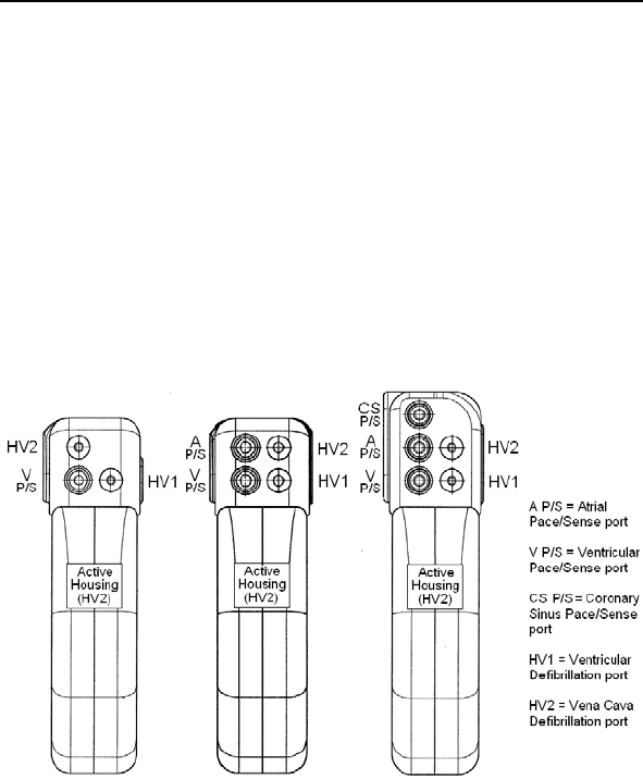
158 Lumax Technical Manual
4.5 Lead to Device Connection
The Lumax ICD/CRT-Ds have been designed and are
recommended for use with a defibrillation lead systems having
one IS-1 connector for ventricular sensing and pacing and up to
two DF-1 connectors for delivery of shock therapy. A separate
bipolar atrial lead with IS-1 connector is required for atrial sensing
and pacing functions and the CS lead for biventricular pacing
(LV). Figure 15 depicts the configuration of the header ports on
the Lumax 300/340 ICD/CRT-Ds, where HV1/RV and HV2/SVC
are for DF-1 connectors, and A P/S and V P/S are for IS-1
connectors. Figure 16 depicts the configuration of the header
ports on the Lumax 500/540, 600/640 and 700/740 ICD/CRT-D
devices.
VR(-T) DR(-T)/VR-T DX HF(-T)
Figure 15. Lumax 300/340 ICD and CRT-D Header Ports
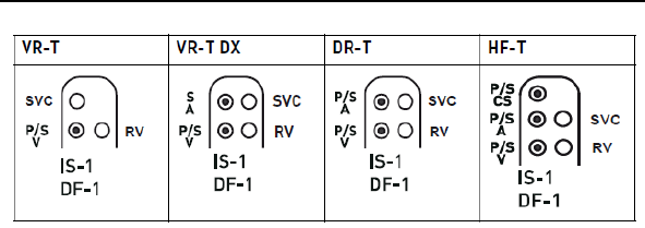
Lumax Technical Manual 159
Figure 16. Lumax 500/540, 600/640 & 700/740 ICDs and CRT-D
Header Ports

160 Lumax Technical Manual
CAUTION
Connector Compatibility - ICD/CRT-D and lead system
compatibility should be confirmed prior to the implant
procedure. Consult your BIOTRONIK representative
regarding lead/pulse generator compatibility prior to the
implantation of an ICD/CRT-D system. For further
information, please refer to Appendix A.
Setscrew Adjustment – Back-off the setscrew(s) prior to
insertion of lead connector(s) as failure to do so may result in
damage to the lead(s), and/or difficulty connecting lead(s).
Cross Threading Setscrew(s) – To prevent cross threading
the setscrew(s), do not back the setscrew(s) completely out
of the threaded hole. Leave the torque wrench in the slot of
the setscrew(s) while the lead is inserted.
Tightening Setscrew(s) – Do not overtighten the
setscrew(s). Use only the BIOTRONIK supplied torque
wrench.
Sealing System – Be sure to properly insert the torque
wrench into the perforation at an angle perpendicular to the
connector receptacle. Failure to do so may result in damage
to the plug and its self-sealing properties.
Far-Field Sensing of signals from the atrium in the
ventricular channel or ventricular signals in the atrial channel
should be avoided by appropriate lead placement,
programming of pacing/sensing parameters, and maximum
sensitivity settings. If it is necessary to modify the Far Field
Blanking parameter, the parameter should be lengthened
only long enough to eliminate far-field sensing as evidenced
on the IEGMs. Extending the parameter unnecessarily may
cause undersensing of actual atrial or ventricular events.
Refer to the following steps when connecting the leads to the
device.

Lumax Technical Manual 161
1. Confirm that the setscrews are not protruding into the
connector receptacles. To retract a setscrew, insert the
enclosed torque wrench through the perforation in the
self-sealing plug at an angle perpendicular to the lead
connector until it is firmly placed in the setscrew. Rotate
the wrench counterclockwise until the receptacle is clear
of obstruction.
2. Insert the lead connector into the connector port of the
ICD/CRT-D without bending the lead until the connector
pin becomes visible behind the setscrew. Hold the
connector in this position. If necessary, apply silicone oil
only to the o-rings on the connector (not the connector
pin).
3. Insert the enclosed torque wrench through the perforation
in the self-sealing plug at an angle perpendicular to the
lead connector until it is firmly placed in the setscrew.
4. Securely tighten the setscrew of the connector clockwise
with the torque wrench until torque transmission is limited
by the wrench.
5. Carefully retract the torque wrench. The perforation will
self-seal.
4.6 Blind Plug Connection
The Lumax DR ICD and HF CRT-D are shipped with a blind plug
(pre inserted) in an unused header port. Refer to the following
steps when connecting blind plugs to the device.
1. Confirm that the setscrews are not protruding into the
connector receptacles. To retract a setscrew, insert the
enclosed torque wrench through the perforation in the
self-sealing plug at an angle perpendicular to the lead
connector until it is firmly placed in the setscrew. Rotate
the wrench counterclockwise until the receptacle is clear
of obstruction.
2. Insert the blind plug into the connector port of the
ICD/CRT-D until the connector pin becomes visible
behind the setscrew.
3. Insert the enclosed torque wrench through the perforation
in the self-sealing plug at an angle perpendicular to the
connector until it is firmly placed in the setscrew.
4. Securely tighten the setscrew of the connector clockwise
with the torque wrench until torque transmission is limited
by the wrench.

162 Lumax Technical Manual
5. Carefully retract the torque wrench. The perforation will
self-seal.
CAUTION
Blind Plug - A blind plug must be inserted and firmly
connected into any unused header port to prevent chronic
fluid influx and possible shunting of high energy therapy.
4.7 Program the ICD/CRT-D
Program the ICD/CRT-D to appropriately treat the patient’s
arrhythmias and other therapy needs. The information obtained
during the lead system evaluation should be helpful in tailoring
the various parameters of the ICD/CRT-D to treat each individual
patient. The detection and therapy status of the ICD/CRT-D may
be activated for testing purposes once all of the lead connectors
have been securely fastened in the device header ports. The
physician shall be made aware of the program that is in effect
after the patient leaves the office, by viewing the parameters
displayed on the programmer screen after the device has been
programmed and interrogated.
CAUTION
Programmed Parameters – Program the device parameters
to appropriate values based on the patient’s specific
arrhythmias and condition.
Programmers - Use only BIOTRONIK’s ICS 3000 or
Renamic programmers to communicate with the device.
Defibrillation Threshold - Be aware that changes in the
patient’s condition, drug regimen, and other factors may
change the defibrillation threshold (DFT) which may result in
non-conversion of the arrhythmia post-operatively.
Successful conversion of ventricular fibrillation or ventricular
tachycardia during arrhythmia conversion testing is no
assurance that conversion will occur post-operatively.

Lumax Technical Manual 163
WARNING
Unwanted Shocks – Always program ICD therapy to OFF
prior to handling the device to prevent the delivery of shocks
to the patient or the person handling the device during the
implant procedure.
4.8 Implant the ICD/CRT-D
The ICD/CRT-D may be placed in the pocket at this time. Place
the device into the pocket with either side facing up (it can be
interrogated and programmed from either side). Carefully coil any
excess lead length behind the ICD/CRT-D.
The pacing and sensing functions of the device should be
evaluated. It is also recommended that at least one induction and
device conversion be done prior to closing the pocket. This will
ensure that the lead system has been securely connected to the
device and has not changed position.
CAUTION
Connector Compatibility - ICD/CRT-D and lead system
compatibility should be confirmed prior to the implant
procedure. Consult your BIOTRONIK representative
regarding lead/pulse generator compatibility prior to the
implantation of an ICD/CRT-D system. For further
information, please refer to Appendix A.
Shock Impedance – If the shock impedance is less than
twenty-five ohms (25 Ω), reposition the lead system to allow
a greater distance between the electrodes. Never implant the
device with a lead system that has a measured shock
impedance of less than twenty-five ohms (25Ω). Damage to
the device may result.

164 Lumax Technical Manual
WARNING
Resuscitation Availability - Do not perform induction testing
unless an alternate source of patient defibrillation such as an
external defibrillator is readily available. In order to implant
the ICD/CRT-D system, it is necessary to induce and convert
the patient’s ventricular tachyarrhythmias.
CAUTION
Pacing Threshold - Testing of the pacing threshold by the
ICD/CRT-D system should be performed with the pacing rate
programmed to a value higher than the patient's intrinsic rate.
Defibrillation Threshold - Be aware that the changes in the
patient’s condition, drug regimen, and other factors may
change the defibrillation threshold (DFT) which may result in
non-conversion of the arrhythmia post-operatively.
Successful conversion of ventricular fibrillation or ventricular
tachycardia during arrhythmia conversion testing is no
assurance that conversion will occur post-operatively.
Electromagnetic interference (EMI) signals present in
hospital and medical environments may affect the function of
any ICD/CRT-D or pacemaker. The ICD/CRT-D is designed
to selectively filter out EMI noise. However, due to the variety
of EMI signals, absolute protection from EMI is not possible
with this or any other ICD/CRT-D.
The ICD/CRT-D system should have detection and therapy
disabled prior to performing any of the following medical
procedures. In addition, the ICD/CRT-D should be checked
after the procedures to assure proper programming:
Electrocautery - Electrosurgical cautery could induce
ventricular arrhythmias and/or fibrillation, or may cause
device malfunction or damage. If use of electrocautery is
necessary, the current path and ground plate should be kept
as far away from the pulse generator and leads as possible
(at least 6 inches (15 cm)).

Lumax Technical Manual 165
Prior to surgically closing the pocket, the telemetry contact should
be evaluated to help ensure chronic programmer communication.
Close the device pocket using standard surgical technique. As
the final step at device implant and each patient follow-up, the
permanent program should be retransmitted to the ICD/CRT-D.
Typically, each device that you receive is in the “Shipment Mode”.
This mode includes factory settings that control the charge
current of automatic capacitor reformations to avoid the possibility
of temporary low battery readings. Shipment mode is
automatically deactivated when electrophysiological tests (e.g.,
Impedance Measurement) are initiated by the programmer. The
following can be used to verify status of the shipment mode:
The shipment mode is ON if the device displays
"Shipment Mode Active" in the event list
The Shipment Mode is OFF if the device does not display
"Shipment Mode Active" in the event list
Complete the Medical Device Registration Form provided with the
ICD/CRT-D and return it to BIOTRONIK.

166 Lumax Technical Manual

Lumax Technical Manual 167
5. Follow-up Procedures
5.1 General Considerations
An ICD/CRT-D follow-up serves to verify appropriate function of
the ICD/CRT-D system, and to optimize the programmable
parameter settings.
In addition to evaluating the patient’s stored therapy history and
electrograms, acute testing of sensing and pacing is
recommended. The physician shall be made aware of the
program that is in effect after the patient leaves the office after
each follow-up, by viewing the parameters displayed on the
programmer screen after the device has been programmed and
interrogated. As the final step at device implant and each patient
follow-up, the permanent program should be retransmitted to the
ICD/CRT-D. Due to longevity concerns, it is recommended the
physician schedule a patient follow-up visit every 3 months.
WARNING
Resuscitation Availability - Do not perform induction
testing unless an alternate source of patient defibrillation
such as an external defibrillator is readily available. In order
to implant the ICD/CRT-D system, it is necessary to induce
and convert the patient’s ventricular tachyarrhythmias.
CAUTION
Programming Wand Separation Distance – The wand
(with magnet) must not be placed closer than 2 cm to the
device (implanted or out of the box). Programming wand
(with magnet) distance closer than 2 cm may damage the
device.

168 Lumax Technical Manual
5.2 Longevity
The service time of an ICD/CRT-D can vary based on several
factors, including the number of charge sequences, programmed
parameters, number of tachyarrhythmias detected, relative
amount of bradycardia pacing required, pacing lead impedance,
storage time, battery properties, and circuit operating
characteristics. Service time is the time from beginning of service
(BOS) to the elective replacement indication (ERI). To assist the
physician in determining the optimum time for ICD/CRT-D
replacement, a replacement indicator is provided that notifies the
user that replacement within a certain period of time is required.
Upon reaching ERI, the battery has at least enough energy left to
continue monitoring for three months along with the ability to
deliver six high-energy shocks. After this period, all
tachyarrhythmia detection and tachyarrhythmia therapy is
disabled.
CAUTION
Charge Time - When preparing a high energy shock the
charge circuit stops charging the capacitors after 20 seconds,
and delivers the stored energy as shock therapy. After the
device reaches ERI the stored energy may be less than the
maximum programmable energy for each shock.
The projected service times from beginning of service (BOS) to
elective replacement indication (ERI) are listed in the following
tables. All estimates were calculated assuming a pacing rate of
60 ppm with a pulse width of 0.4 ms and pulse amplitude of 2.8
volts and 500 ohm pacing impedance with all shocks at maximum
programmable energy at 37C. It is assumed that the shocks are
equally spaced throughout the life of the ICD/CRT-D. The
estimates associated with 0% pacing support assume the
ICD/CRT-D is sensing an intrinsic sinus rhythm at a rate of
70 bpm. The tables represent the mean longevity estimates for
the specified devices. If there are multiple available batteries for a
particular device, the worst case longevity option is presented.

Lumax Technical Manual 169
5.2.1 Lumax 300/340 Devices
The single chamber Lumax (Lumax 300 VR, Lumax 340 VR,
Lumax 300 VR-T, and Lumax 340 VR-T) ICDs are intended to
operate for more than 4 years under normal use. Table 37
provides longevity estimates for the Lumax 340 VR-T ICD, which
has the worst case longevity estimates of the devices listed
above. The table provides several different support scenarios. It
is assumed that the shocks are equally spaced throughout the life
of the ICD.
Table 37 Lumax 340 VR-T Longevity Estimates
Pacing Support
Shocks per year
(max energy)
0% 15% 50% 100%
4 6.0 5.8 5.4 4.9
5 5.7 5.5 5.2 4.7
6 5.4 5.3 4.9 4.5
7 5.2 5.0 4.7 4.4
8 5.0 4.8 4.5 4.2
9 4.8 4.6 4.4 4.0
10 4.6 4.4 4.2 3.9
11 4.4 4.3 4.1 3.8
12 4.2 4.1 3.9 3.7
The dual chamber Lumax (Lumax 300 DR, Lumax 340 DR,
Lumax 300 DR-T, and Lumax 340 DR-T) ICDs are intended to
operate for more than 5 years under normal use. Table 38
provides longevity estimates for the Lumax 340 DR-T ICD (order
number 355267), which has the worst case longevity estimates of
the devices listed above. The table provides several different
support scenarios. It is assumed that the shocks are equally
spaced throughout the life of the ICD.

170 Lumax Technical Manual
Table 38 Lumax 340 DR-T Longevity Estimates
Pacing Support
Shocks per year
(max energy)
0% 15% 50% 100%
4 5.7 5.4 4.8 4.1
5 5.4 5.1 4.6 3.9
6 5.2 4.9 4.4 3.8
7 5.0 4.7 4.2 3.7
8 4.8 4.5 4.1 3.6
9 4.6 4.4 3.9 3.4
10 4.4 4.2 3.8 3.3
11 4.2 4.0 3.7 3.2
12 4.1 3.9 3.6 3.2
Table 39 and Table 40 provide longevity estimates for the
Lumax 300 & 340 HF-T CRT-D with Greatbatch batteries. The
tables are limited to 100% ventricular pacing because that is the
goal for each CRT-D device. It is assumed that the shocks are
equally spaced throughout the life of the ICD.
Table 39 Lumax 300 HF-T Longevity Estimates
Shocks per year 100% Pacing Support
(in years)
4 5.4
5 5.3
6 5.2
7 5.1
8 4.9
9 4.8
10 4.7
11 4.6
12 4.5

Lumax Technical Manual 171
Table 40 Lumax 340 HF-T Longevity Estimates
Shocks per year 100% Pacing Support
(in years)
4 5.2
5 5.0
6 4.8
7 4.7
8 4.6
9 4.4
10 4.3
11 4.2
12 4.1
The Lumax 300/340 HF CRT-Ds (Lumax 300 HF-T, and
Lumax 340 HF-T) are intended to operate for more than 5 years
under normal use.
5.2.2 Lumax 500/540 Devices
The single chamber Lumax 500/540 ICD variants
(Lumax 500 VR-T and Lumax 540 VR-T) of are intended to
operate for more than 6 years under normal use. Table 41
provides longevity estimates for these devices. The table provides
several different support scenarios. It is assumed that the shocks
are equally spaced throughout the life of the ICD.
Table 41 Lumax VR-T Longevity Estimates
Pacing Support
Device Shocks per
year
0% 15% 50% 100%
4 8.3 8.1 7.6 7.0
8 7.0 6.9 6.5 6.1
500 VR-T
12 6.1 6.0 5.7 5.4
4 8.7 8.5 8.0 7.4
8 7.1 6.9 6.6 6.2
540 VR-T
12 6.0 5.9 5.6 5.3
172 Lumax Technical Manual
The dual-chamber Lumax 500/540 variants (Lumax 500 DR-T,
and Lumax 540 DR-T) of ICDs are intended to operate for more
than 6 years under normal use. Table 42 provides longevity
estimates for these devices. The table provides several different
support scenarios. It is assumed that the shocks are equally
spaced throughout the life of the ICD.
Table 42 Lumax DR-T Longevity Estimates
Pacing Support
Device Shocks per
year
0% 15% 50% 100%
4 7.9 7.5 6.7 5.8
8 6.7 6.4 5.8 5.2
500 DR-T
12 5.9 5.6 5.2 4.6
4 8.3 7.9 7.1 6.2
8 6.8 6.5 6.0 5.4
540 DR-T
12 5.8 5.6 5.2 4.7
The Lumax 540 VR-T DX ICDs are intended to operate for more
than 6 years under normal use. Table 43 provides longevity
estimates for these devices. The table provides several different
support scenarios. It is assumed that the shocks are equally
spaced throughout the life of the ICD.
Table 43 Lumax VR-T DX Longevity Estimates
Pacing Support
Device Shocks per
year
0% 15% 50% 100%
4 8.3 8.1 7.6 7.1
8 6.8 6.6 6.4 6.0
540 VR-T
DX 12 5.8 5.7 5.4 5.2
The Lumax 500/540 HF-T variants of ICDs are intended to
operate for more than 6 years under normal use. Table 44
provides longevity estimates for these devices with Greatbatch
batteries. The table provides several different support scenarios.
It is assumed that the shocks are equally spaced throughout the
life of the ICD.

Lumax Technical Manual 173
Table 44 Lumax 500/540 HF-T Longevity
Estimates
Pacing Support
Device Shocks per year 100%
4 5.6
5 5.5
6 5.4
7 5.2
8 5.1
9 5.0
10 4.9
11 4.7
500 HF-T
12 4.6
4 5.3
5 5.1
6 5.0
7 4.8
8 4.6
9 4.5
10 4.4
11 4.3
540 HF-T
12 4.1
Upon reaching ERI, the battery has enough energy left to
continue monitoring for three months and to deliver six high
energy shocks. The estimates associated with duration of ERI
assume the ICD/CRT-D is sensing an intrinsic sinus rhythm at a
rate of 70 bpm. After this period the device is at EOS (End of
Service) and requires explantation. Once at EOS, all
tachyarrhythmia detection and therapy is disabled. The ERI and
EOS voltages are listed in the Table 45.
Table 45 ERI and EOS Voltages
Operating Mode Voltage
Elective Replacement Indicator (ERI) 2.50 Volts
End of Service (EOS) 1.75 Volts
174 Lumax Technical Manual
5.2.3 Lumax 600/640 & 700/740 Devices
Table 41 provides longevity estimates for the single chamber
Lumax 600/640 & 700/740 ICD variants (Lumax 600/700 VR-T
and Lumax 640/740 VR-T). The table provides several different
support scenarios. It is assumed that the shocks are equally
spaced throughout the life of the ICD.
Table 46 Lumax VR-T Longevity Estimates
Pacing Support
Device Shocks per
year
0% 15% 50% 100%
4 9.91 9.60 8.95 8.17
8 8.32 8.10 7.64 7.06
600 VR-T
700 VR-T 12 7.17 7.01 6.66 6.21
4 10.21 9.92 9.31 8.55
8 8.20 8.01 7.60 7.09
640 VR-T
740 VR-T 12 6.84 6.71 6.42 6.05
Table 42 provides longevity estimates for the dual-chamber
Lumax 600/640 and 700/740 ICD variants (Lumax 600/700 DR-T,
and Lumax 640/740 DR-T). The table provides several different
support scenarios. It is assumed that the shocks are equally
spaced throughout the life of the ICD.
Table 47 Lumax DR-T Longevity Estimates
Pacing Support
Device Shocks per
year
0% 15% 50% 100%
4 8.95 8.42 7.40 6.31
8 7.62 7.24 6.47 5.61
600 DR-T
700 DR-T 12 6.64 6.34 5.74 5.06
4 9.31 8.80 7.80 6.71
8 7.59 7.25 6.55 5.77
640 DR-T
740 DR-T 12 6.40 6.16 5.65 5.05
Table 43 provides longevity estimates for the
Lumax 640/740 VR-T DX ICDs. The table provides several
different support scenarios. It is assumed that the shocks are
equally spaced throughout the life of the ICD.
Lumax Technical Manual 175
Table 48 Lumax VR-T DX Longevity Estimates
Pacing Support
Device Shocks per
year
0% 15% 50% 100%
4 9.31 9.07 8.54 7.89
8 7.59 7.43 7.07 6.62
640 VR-T
DX
740 VR-T
DX 12 6.40 6.29 6.03 5.70
Table 44 provides longevity estimates for the Lumax 600/640 and
700/740 HF-T variants of CRT-Ds. The table provides several
different support scenarios. It is assumed that the shocks are
equally spaced throughout the life of the CRT-D.
Table 49 Lumax 600/640 & 700/740 HF-T
Longevity Estimates
Pacing Support
Device Shocks per year 100%
4 6.09
5 5.93
6 5.77
7 5.63
8 5.49
9 5.36
10 5.23
11 5.11
600 HF-T
700 HF-T
12 5.00
4 5.72
5 5.53
6 5.34
7 5.17
8 5.01
9 4.86
10 4.72
11 4.59
640 HF-T
740 HF-T
12 4.46

176 Lumax Technical Manual
Upon reaching ERI, the battery has enough energy left to
continue monitoring for three months and to deliver six high
energy shocks. The estimates associated with duration of ERI
assume the ICD/CRT-D is sensing an intrinsic sinus rhythm at a
rate of 70 bpm. After this period the device is at EOS (End of
Service) and requires explantation. Once at EOS, all
tachyarrhythmia detection and therapy is disabled. The ERI
voltages are listed in the Table 45.
Table 50 ERI and EOS Voltages
Operating Mode Voltage
Elective Replacement Indicator (ERI) 2.50 & 2.85 Volts
5.3 Explantation
Explanted ICDs/CRT-Ds, lead systems, and accessories may not
be reused. Please complete the appropriate out of service (OOS)
form and return it to BIOTRONIK with the explanted devices. All
explanted devices should be sent either to the local BIOTRONIK
representative or the BIOTRONIK home office for expert disposal.
Contact BIOTRONIK if you need assistance with returning
explanted devices. If possible, the explanted devices should be
cleaned with a sodium-hyperchlorine solution of at least 1%
chlorine and then washed with water prior to shipping.
The pulse generator should be explanted before the cremation of
a deceased patient.
WARNING
Unwanted Shocks – Always program ICD Therapy to OFF
prior to handling the device to prevent the delivery of serious
shocks to the patient or the person handling the device
during the implant procedure.

Lumax Technical Manual 177
CAUTION
Device Incineration – Never incinerate the ICDs/CRT-Ds
due to the potential for explosion. The ICD/CRT-D must be
explanted prior to cremation.
Explanted Devices – Return all explanted devices to
BIOTRONIK.

178 Lumax Technical Manual

Lumax Technical Manual 179
6. Technical Specifications
The following are the technical specifications for the
Lumax ICDs/CRT-Ds. The ranges are presented in the format:
x…(y)…z
where x = the lowest value, y = the increment, and z = the largest
value.
Mechanical Properties
Lumax
300/500
600/700
Lumax
340/540
640/740
Lumax
500
600/700
HF-T
Lumax
340/540
640/740
HF-T
Dimensions 66 mm x
55 mm x
12 mm
66 mm x
55 mm x
13 mm
66 mm x
59 mm x
12 mm
66 mm x
59 mm x
13 mm
Volume 34.6 cm3 37.2 cm3 37.1 cm3 39.8 cm3
Mass 81 g 92 g 83 g 94 g
Housing Titanium
Header Epoxy resin
Seal Plug Silicone
VR-T
Lead Ports
1 x 3.2 mm IS-1 Bipolar
2 x 3.2 mm DF-1
DR-T
Lead Ports
2 x 3.2 mm IS-1 Bipolar
2 x 3.2 mm DF-1
3 x 3.2 mm IS-1 Bipolar
2 x 3.2 mm DF-1
Parameter Range Standard
Bradycardia
Atrial Sensing Parameters
Sensing STD - standard,
OFF - inactive
STD
Minimum threshold 0.2...(0.1)...2.0 mV 0.4 mV
Far-field protection
after Vp
50...(25)...225 ms 75 ms
Far-field protection
after Vs
Off, 25...(25)...225 ms 75 ms
Upper threshold 50; 75; 87.5 % 50 %

180 Lumax Technical Manual
Parameter Range Standard
Upper threshold
(Lumax 700/740 &
600/640 only)
25, 50; 75 % 50 %
Lower threshold 12.5; 25; 50 % 25 %
Lower threshold
(Lumax 700/740 &
600/640 only)
25 25 %
Hold of upper
threshold after As
(Lumax 700/740 &
600/640 only)
350 ms 350 ms
Hold of upper
threshold after Ap
(Lumax 700/740 &
600/640 only)
350 ms 350 ms
Initial Noise Interval
(Lumax 700/740 &
600/640 only)
110 ms 110 ms
High pass
(Lumax 700/740 &
600/640 only)
18 Hz 18 Hz
Right-ventricular Sensing Parameters
Sensing RV STD - standard,
TWS - extended T-wave
suppression,
VFS - extended VF
sensitivity
STD
Minimum threshold 0.5...(0.1)...2.5 mV 0.8 mV
Blanking after atrial
pacing 50...(10)...100 ms 50 ms
(N/A
VR-T DX)
Upper threshold 50; 75; 87.5 % 50 %
Upper threshold
(Lumax 700/740 &
600/640 only)
50; 75 % 50 %
Lower threshold 12.5; 25; 50% 25 %
Lower threshold
(Lumax 700/740 &
600/640 only)
25; 50% 25 %

Lumax Technical Manual 181
Parameter Range Standard
Hold of upper
threshold
100...(20)...600 ms 360 ms
Hold of upper
threshold after Vs
(Lumax 700/740 &
600/640 only)
110, 150...(50)...500 ms
110 ms (VFS)
350 ms
Hold of upper
threshold after Vp
(Lumax 700/740 &
600/640 only)
110, 150...(50)...500 ms
110 ms (VFS)
400 ms
Initial Noise Interval
(Lumax 700/740 &
600/640 only)
110 …(10) … 200 ms 110 ms
High pass
(Lumax 700/740 &
600/640 only)
24, 32 Hz
32 Hz (TWS, VFS)
24 Hz
Low pass
(Lumax 700/740 &
600/640 only)
100 Hz 100 Hz
Left-ventricular Sensing Parameters
Sensing LV STD - standard,
OFF - inactive
STD
Min. threshold 0.5...(0.1)...2.5 mV 1.6 mV
Min. threshold
(Lumax 700/740 &
600/640 only)
0.5…(0.1)…2.5….(0.5)….
5.0 mV
1.6 mV
Blanking after atrial
pacing
= Safety window 100 ms
(N/A
VR-T DX)
Upper threshold 50; 75; 87.5% 50 %
Upper threshold
(Lumax 700/740 &
600/640 only)
50; 75 % 50 %
Hold of upper
threshold
100...(20)...600 ms 360 ms
Hold of upper
threshold after Vs
(Lumax 700/740 &
600/640 only)
110, 150...(50)...500 ms 350 ms

182 Lumax Technical Manual
Parameter Range Standard
Hold of upper
threshold after Vp
(Lumax 700/740 &
600/640 only)
110, 150...(50)...500 ms 400 ms
Lower threshold 12.5; 25; 50 % 50 %
Lower threshold
(Lumax 700/740 &
600/640 only)
50 % 50 %
In channel/Cross channel Blanking
In-channel blank
after RV pace
Auto, 100...(10)...350 ms Auto
RV Blanking after
RV pacing
(Lumax 700/740 &
600/640 only)
100...(10)...350 ms 120 ms
In-channel blank
after LV pace
Auto, 100...(10)...350ms Auto
LV Blanking after LV
pacing
(Lumax 700/740 &
600/640 only)
100...(10)...350 ms 120 ms
LV cross-blank after
RV pace
50...(10)...100 ms 80 ms
RV cross-blank after
LV pace
50...(10)...100 ms 80 ms
Polarity Pace/Sense
LV polarity pace LV-tip -> LV-ring
(bipolar (1)),
LV-tip -> RV-ring
(common ring bipolar (2)),
LV-ring -> LV-tip
(inverse bipolar (3)),
LV-ring -> RV-ring
(ring ring bipolar (4))
LV-tip -> RV-
ring
LV polarity pace
(Lumax 700/740 &
600/640 models
only)
LV-tip -> housing
(unipolar (5)),
LV polarity sense UNIP (LV-tip/housing),
BIPL (LV-tip/LV-ring)
UNIP

Lumax Technical Manual 183
Parameter Range Standard
Shock Path (Valid
for all shocks
including the pain-
free shock
impedance)
RV -> SVC + ICD
(Housing)
RV -> ICD (500/540 only)
RV -> SVC (500/540
only)
RV -> SVC +
ICD
Pulse Amplitudes and Pulse Widths
Pulse amplitude 0.2...(0.1)...6.2, 7.5 V 2.8 V
Pulse amplitude
(Lumax 700/740 &
600/640 models
only)
0.5…(0.25)…4.0…(0.5)…
..6.0, 7.5 V
2.5 V
Pulse width 0.4, 0.5, 0.7, 1.0, 1.2, 1.5
ms
0.4 ms
Pulse width
(Lumax 700/740 &
600/640 models
only)
0.4, 0.5…(0.25)…1.5 ms 0.4 ms
Automatic Threshold Measurement (ATM)
For Lumax 500/540 Models Only
RV ON; OFF ON1
LV (HF-T Only) ON; OFF ON
Active Threshold Tracking (ATT)
For Lumax 700/740 & 600/640 Models Only
RV ON; OFF ON2
LV (HF-T Only) ON; OFF ON
Thoracic Impedance Measurement (TI)
For Lumax 700/740 & 600/640 Models Only
TI ON; OFF ON
Mode
Modes DDD, DDDR, DDI, DDIR,
VDD, VDDR, VDI, VDIR,
VVI, VVIR, AAI, AAIR,
OFF
DDD
1 The Standard Program for the ATM feature is ON only for the
Lumax 500/540 VR-T
2 The Standard Program for the ATT feature is ON only for the
Lumax 700/740 & 600/640 VR-T

184 Lumax Technical Manual
Parameter Range Standard
Modes (Lumax
700/740 & 600/640
models only)
DDD, DDDR, DDI, DDIR,
D00, VDD, VDDR, VDI,
VDIR, VVI, VVIR, V00,
AAI, AAIR, OFF
Modes (VR-T DX
Only)
VDD, VDDR, VDI, VDIR,
VVI, VVIR, OFF
Modes (Lumax
740/640 VR-T DX
Only)
VDD, VDDR, VDI, VDIR,
VVI, VVIR, V00, OFF
VVI
Basic Rate Day/Night
Basic rate 30..(5)..100..(10)..160
bpm
60 bpm
Night rate OFF, 30..(5)..100 bpm OFF
Night beginning 00:00..(1 min)..23:59 h:m [22:00 h:m]
Night ending 00:00..(1 min)..23:59 h:m [06:00 h:m]
Rate Hysteresis
Rate hysteresis OFF, -5..(-5)..-90 ppm OFF
Rate hysteresis
(Lumax 740/640
VR-T DX Only)
OFF, -5…(-5)… -25…
(-20)…-65 bpm
OFF
Repetitive OFF; 1..(1)..15 [OFF]
Scan OFF; 1..(1)..15 [OFF]
Scan / Repetitive
(Lumax 740/640
VR-T DX Only)
OFF; ON (10) [ON(10)]
AV Delay
AV delay Low, medium, high, fixed,
individ.
Low
AV delay 1 40..(5)..350 ms 150 ms
AV delay 1 after
pace
(Lumax 740/640
VR-T DX Only)
15, 40..(5)..350 ms -
AV delay 1 after
sense
(Lumax 740/640
VR-T DX Only)
=AV delay 1 after pace +
Sense compensation
-
AV rate 1 30..(10)..120 bpm 60 bpm

Lumax Technical Manual 185
Parameter Range Standard
AV rate 1
(Lumax 740/640
VR-T DX Only)
50..(10)..130 bpm 60 bpm
AV delay 2 40..(5)..350 ms 120 ms
AV delay 2
(Lumax 740/640
VR-T DX Only)
15, 40..(5)..350 ms -
AV rate 2 70..(10)..160 bpm 130 bpm
AV rate 2
(Lumax 740/640
VR-T DX Only)
60..(10)..140 bpm 130 bpm
Sense
compensation
OFF; -5..(-5)..-60 ms -30 ms
(N/A
VR-T DX)
Sense
compensation
(Lumax 740/640
VR-T DX Only)
OFF; -5..(-5)..-120 ms -40 ms
(N/A
VR-T DX)
AV-hysteresis mode OFF,
positive,
negative
OFF
AV hysteresis 10..(10)..150 ms [50 ms]
AV hysteresis
(positive)
(Lumax 740/640
VR-T DX Only)
70, 110, 150, 200 ms [70 ms]
AV hysteresis
(negative)
(Lumax 740/640
VR-T DX Only)
10..(10)..150 ms [50 ms]
AV repetitive
(positive)
OFF; 1..(1)..10 [5]
AV repetitive
(negative)
OFF;
1..(1)..15..(5)..100..(10)..1
80
[180]
AV scan / repetitive
(positive)
(Lumax 740/640
VR-T DX Only)
OFF; ON (5) [ON (5)]

186 Lumax Technical Manual
Parameter Range Standard
AV repetitive
(negative)
(Lumax 740/640
VR-T DX Only)
ON (180) ON (180)
AV scan OFF, 1..(1)..10 [5]
I-Opt
I-Opt OFF, ON OFF
AV hysteresis at I-
Opt
400 ms 400 ms
AV repetitive at I-
Opt
OFF; 1..(1)..10 [5]
AV scan at I-Opt OFF, 1..(1)..10 [5]
AV scan / repetitive
at I-Opt
(Lumax 740/640
VR-T DX Only)
ON (5) [ON(5)]
AV max at I-Opt 400 ms 400ms
Post-ventricular Atrial Refractory Period (PVARP)
PVARP 175..(25)..600 ms, Auto 250 ms
PVARP
(Lumax 740/640
VR-T DX Only)
175..(25)..600 ms, Auto 225 ms
Auto PVARP OFF, ON OFF
VES Classification (VES Lock-in Protection)
VES discrimination
after As
250..(50)..450 ms 350 ms
VES discrimination
after As
(Lumax 740/640
VR-T DX Only)
250..(50)..500 ms 350 ms
Rate Adaptation (Acceleration Sensor)
Maximum sensor
rate
90..(5)..160 bpm 120 bpm
Maximum sensor
rate (Lumax 740/640
VR-T DX Only)
80..(10)..160 bpm 120 bpm

Lumax Technical Manual 187
Parameter Range Standard
Sensor gain 1.0; 1.1; 1.3; 1.4; 1.6; 1.8;
2.0; 2.2; 2.6; 3.0; 3.3; 3.7;
4.0; 4.5; 5.0; 6.0; 7.0; 8.0;
9.0; 10; 11; 12; 14; 16;
18; 20; 22; 24; 28; 32; 35;
40
6.0
Sensor gain
(Lumax 700/740 &
600/640 only)
AUTO, Very low (1.3),
Low (3), Medium (6),
High (12), Very high (26)
Medium (6)
Auto Sensor gain OFF, ON OFF
Sensor threshold
(numbers are not
displayed on screen)
Very low = 0
Low = 3
Medium = 7
High = 11
Very high = 15
Medium
Rate increase 0.5; 1..(1)..6 ppm/cycle 2 bpm/cycle
Rate increase
(Lumax 700/740 &
600/640 only)
1, 2, 4, 8 bpm/cycle 2 bpm/cycle
Rate drop 0.25..(0.25)..1.25
ppm/cycle
0.5
ppm/cycle
Rate decrease
(Lumax 700/740 &
600/640 only)
0.1, 0.2, 0.5, 1.0
bpm/cycle
0.5
ppm/cycle
Upper Tracking Rate (UTR)
Upper tracking rate 90..(10)..160 bpm 130 bpm
Upper tracking rate
atrium
OFF, 240 bpm 240 bpm
(N/A
VR-T DX)
Upper tracking rate
atrium
(Lumax 700/740 &
600/640 only)
OFF, 175, 200. 240 bpm 200 ppm
(N/A
VR-T DX)
Mode Switching
Intervention rate OFF, 100..(10)..250 bpm 160 bpm
Intervention rate
(Lumax 700/740 &
600/640 only)
OFF, 120..(10)..200 bpm 160 bpm
Activation criterion X 3..(1)..8 5

188 Lumax Technical Manual
Parameter Range Standard
Deactivation
criterion Z
3..(1)..8 5
Mode DDI, DDIR at permanent
DDD(R)
VDI, VDIR at permanent
VDD(R)
DDI
[VDI]
Modes (VR-T DX
Only)
VDI, VDIR at permanent
VDD(R)
VDI
Change in basic rate OFF, +5 ... (5) ...+30 bpm +10 bpm
Post-Mode Switch Response (PMSR)
Post-ModeSw rate OFF, +5 ... (5) ...+50 bpm +10 bpm
Post-ModeSw
duration
1..(1)..30 min 1 min
PMT Protection
PMT
detection/terminatio
n
OFF, ON ON
VA criterion 250..(10)..500 ms 350 ms
Detection
Detection/Therapy ON, OFF ON
Interval
Interval AT/AF 100….(10)…250 bpm
(240…..600 ms)
200 bpm
Interval VT1 OFF, 270...(10)...600 ms OFF
Interval VT2 OFF, 270...(10)...500 ms OFF
Interval VF OFF, 200...(10)...400 ms 300 ms
Interval VF
(Lumax 700/740 &
600/640 only)
OFF, 240...(10)...400 ms 300 ms
Detection Counter
Detection counter
VT1
10...(2)...60 [16]
Detection counter
VT2
10...(2)...40 [14]
Detection counter
VF – X
6...(1)...30 8
Detection counter
VF – Y
8...(1)...31 12

Lumax Technical Manual 189
Parameter Range Standard
Detection counter
VF – X out of Y
(Lumax 700/740 &
600/640 only)
6 out of 8
8 out of 12
10 out of 14
12 out of 16
16 out of 20
18 out of 24
20 out of 26
22 out of 30
24 out of 30
8 out of 12
Onset
Onset in VT1/2 with
SMART
20% [20%]
Onset VT1 without
SMART
OFF; 4…(4)…32% 20%
Onset VT2 without
SMART
OFF; 4…(4)…32% 20%
Stability
Stability in VT1/2
with SMART
12% [12%]
Stability VT1 without
SMART
OFF; 8…(4)…48 ms 24 ms
Stability VT2 without
SMART
OFF; 8…(4)…48 ms 24 ms
SMART Detection
SMART detection
VT1
OFF, ON [ON]
SMART detection
VT2
OFF, ON [ON]
Sustained VT (without SMART Detection and without
SMART Redetection)
Sustained VT OFF, 00:30, 01:00, 02:00,
03:00, 05:00, 10:00,
15:00, 20:00, 25:00,
30:00 [mm:ss]
[OFF]
Sustained VT
(Lumax 700/740 &
600/640 only)
OFF, 01:00, 02:00, 03:00,
05:00, 10:00, 20:00,
30:00 [mm:ss]
[OFF]
Forced Termination (with SMART Detection Including
SMART Redetection)
Forced termination OFF; 1…(1)…15 min [1 min]

190 Lumax Technical Manual
Parameter Range Standard
Forced termination
(Lumax 700/740 &
600/640 only)
OFF; 1…(1)…10 min [1 min]
Redetection Counter
Redetection counter
VT1
10...(2)...30 [12]
Redetection counter
VT2
10...(2)...30 [10]
SMART Redetection
SMART redetection
(VT1 & VT2)
OFF, ON [ON]
Ventricular Therapy Parameters
Energy 1st shock
and 2nd shock
VT1, VT2 (model
300/500)1
OFF; 1..(1)..16..(2)..30 J 30 J
Energy 1st shock of
VT1, VT2
(Lumax 700/600
only)
OFF; 2..(2)..20..(5)..30 J 30 J
Energy 2nd shock of
VT1, VT2
(Lumax 700/600
only)
OFF; 4..(2)..20..(5)..30 J 30 J
Energy 1st shock
and 2nd shock
VF (model 300/500)
1
1..(1)..16..(2)..30 J 30 J
Energy 1st shock of
VF (Lumax 700/600
only)
2..(2)..20..(5)..30 J 30 J
Energy 2nd shock of
VF (Lumax 700/600
only)
4..(2)..20..(5)..30 J 30 J
1 Programmed values are stored energies.

Lumax Technical Manual 191
Parameter Range Standard
Energy 1st shock
and 2nd shock
VT1, VT2 (model
340/540) 1
OFF; 1..(1)..16..(2)..40 J 40 J
Energy 1st shock of
VT1, VT2
(Lumax 740/640
only)
OFF; 2..(2)..20..(5)..40 J 40 J
Energy 2nd shock of
VT1, VT2
(Lumax 740/640
only)
OFF; 4..(2)..20..(5)..40 J 40 J
Energy 1st shock
and 2nd shock
VF (model 340/540)
1
1..(1)..16..(2)..40 J 40 J
Energy 1st shock of
VF (Lumax 740/640
only)
2..(2)..20..(5)..40 J 40 J
Energy 2nd shock of
VF (Lumax 740/640
only)
4..(2)..20..(5)..40 J 40 J
Number of shocks
(VT1/VT2)
0..(1)..8 [8]
Number of shocks
(VT1/VT2)
(Lumax 700/740 &
600/640 only)
0, 1, 2, 6, 8 [8]
Number of shocks
(VF)
2; 6..(1)..8 8
Number of shocks
(VF)
(Lumax 700/740 &
600/640 only)
6, 8 8
Confirmation (per
zone)
OFF, ON ON
Shock form (per
zone)
Biphasic, Biphasic2 Biphasic

192 Lumax Technical Manual
Parameter Range Standard
Polarity (per zone) Normal,
Reverse,
Alternating
Normal
ATP Parameters
ATP type Burst, Ramp, Burst +
PES
[Burst]
ATP type
(Lumax 700/740 &
600/640 only)
Burst, Ramp [Burst]
ATP attempts OFF, 1…(1)...10 3
ATP attempts
(Lumax 700/740 &
600/640 only)
OFF, 1…(1)...10 [OFF]
S1 number 1...(1)...10 [5]
Add. S1 OFF, ON [ON]
R1-S1 interval 200...(10)...500 ms
(absolute);
70...(5)...95 % (adaptive)
[80 %]
R1-S1 interval
(Lumax 700/740 &
600/640 only)
70...(5)...95 % (adaptive) [80 %]
S1 (RAMP)
decrement
5...(5)...40 ms [10 ms]
Scan decrement OFF, 5...(5)...40 ms [OFF]
S1-S2 interval 200...(10)...500 ms
(absolute);
70...(5)...95 % (adaptive)
[70 %]
Minimal ATP interval 200...(5)...300 ms [200 ms]
Minimal ATP interval
(Lumax 700/740 &
600/640 only)
200 ms -
ATP timeout (not
applicable in Lumax
700/740 & 600/640)
OFF,
00:15...(00:15)...05:00
mm:ss
OFF
ATP optimization OFF, ON OFF
ATP pulse amplitude 7.5 V 7.5 V
ATP pulse width 1.5 ms 1.5 ms
ATP One-Shot Parameter (ATP in VF)
ATP type OFF, Burst, Ramp, Burst
+ PES
OFF

Lumax Technical Manual 193
Parameter Range Standard
ATP type
(Lumax 700/740 &
600/640 only)
OFF, Burst, Ramp Burst
S1 number 1...(1)...10 [5]
S1 number
(Lumax 700/740 &
600/640 only)
1...(1)...10 [8]
R-S1 interval 200...(10)...350 ms
(absolute);
70...(5)...95 % (adaptive)
[80%]
R-S1 interval
(Lumax 700/740 &
600/640 only)
70...(5)...95 % (adaptive) [85%]
S1 decrement 5...(5)...40 ms [10 ms]
S1-S2 interval 200...(10)...350 ms
(absolute);
70...(5)...95 % (adaptive)
[70%]
Stability 12% 12%
ATP attempts 1 [1]
ATP pulse amplitude 7.5 V 7.5 V
ATP pulse width 1.5 ms 1.5 ms
Ventricular NIPS
Lumax 700/740 & 600/640 Only
ATP type Burst, Ramp, Burst +
PES
Ramp
Attempts 1 1
Ventricular Pacing BiV, LV, RV RV
S1 number 1...(1)...25 [5]
R-S1 interval 200...(10)...600 ms
(absolute);
70...(5)...95 % (adaptive)
[80%]
S1 decrement 5...(5)...40 ms [10 ms]
S1-S2 interval 200...(10)...600 ms
simply alterable via [+ / -]
buttons
290
S2-S3 interval OFF, 200...(10)...600 ms
simply alterable via [+ / -]
buttons
OFF

194 Lumax Technical Manual
Parameter Range Standard
S3-S4 interval OFF, 200...(10)...600 ms
simply alterable via [+ / -]
buttons
OFF
Minimum ATP
interval
200 ms
Atrial NIPS
Lumax 700/740 & 600/640 Only
Backup Stimulation
(VVI-Rate)
OFF, 30 .. (10) .. 120
bpm
OFF
Report OFF, 5, 10, 25, 50 mm/s Preference
S1-S1 interval 80…(10)…2000 ms 600 ms
S1 cycles 0...(1)...10 7
S1-S2 interval None, 80...(10)...1000 ms
simply alterable via [+ / -]
buttons
None
S2-S3 interval None, 80...(10)...1000 ms
simply alterable via [+ / -]
buttons
None
S3-S4 interval None, 80...(10)...1000 ms
simply alterable via [+ / -]
buttons
None
Burst rate Min. 30…(10)…250 bpm 150 bpm
Burst rate Start 30…(10)…800 bpm 250 bpm
Burst rate Max. 30…(10)…800 bpm 350 bpm
Post-Shock Pacing
Mode DDI at permanent
DDD(R), DDI (R), AAI(R)
VDI at permanent
VDD(R), VDI(R),
VVI at permanent VVI(R),
OFF
Modes (VR-T DX
Only)
AAI
VDI at permanent
VDD(R), VDI(R),
VVI at permanent VVI(R),
OFF
Basic rate 30 .. (5)..100..(10) .. 160
bpm
60 bpm
Rate hysteresis OFF, -5 .. (-5) .. –65 bpm OFF

Lumax Technical Manual 195
Parameter Range Standard
Rate hysteresis
(Lumax 700/740 &
600/640 only)
OFF -
AV delay 50..(10)..350 ms (fixed
AV delay)
140 ms
Post-shock duration OFF, 00:10 .. (00:10) ..
00:50, 01:00 .. (01:00) ..
10:00 mm:ss
00:10 mm:ss
Post-shock duration
(Lumax 700/740 &
600/640 only)
OFF, 00:10, 00:30, 01:00,
02:00, 05:00, 10:00
mm:ss
00:10 mm:ss
CRT Therapy Parameters
Initially paced
chamber
LV, RV LV
VV delay after Vp 0… (5)… 100 ms 0 ms
Home Monitoring
Home Monitoring OFF, ON OFF
Transmission time Time (hh:mm) [01:00
hh:mm]
Transmission time
(Lumax 700/740 &
600/640 only)
Std., 00:00 ..(01:00) ..
23:00 (hh:mm)
[Std.]
IEGM for therapy
episode
OFF, ON [OFF]
IEGM for therapy
episode
(Lumax 700/740 &
600/640 only)
OFF, ON [ON]
IEGM for monitoring
episode
OFF, ON [OFF]
IEGM for monitoring
episode
(Lumax 700/740 &
600/640 only)
OFF, ON [ON]
Periodic IEGM OFF, 2, 3, 4, 6 months [OFF]
Periodic IEGM
(Lumax 700/740 &
600/640 only)
OFF, Date, 30, 60, 90,
120, 180 days
[90]
Sustained atrial
episode
OFF, 0,5, 6, 12, 18 h [12 h]

196 Lumax Technical Manual
Parameter Range Standard
Sustained atrial
episode
(Lumax 700/740 &
600/640 only)
OFF, 6, 12, 18 h
(5 min, 30 min)
[12 h]
Diagnostics
if Home Monitoring ON: =
Cycle duration
[90] Periodic Recordings
(Lumax 700/740 &
600/640 only) If Home Monitoring OFF:
OFF, 30 .. (30) .. 180
[90]
FCC Statement: (FCC ID: QRILUMAXT, QIRLUMAXT50): This
implant is equipped with an RF transmitter for wireless
communications. This device may not interfere with stations
operating in the 400.150–406.000 MHz band in the
Meteorological Aids, Meteorological Satellite, and Earth
Exploration Satellite Services and must accept any interference
received, including interference that may cause undesired
operation.

Lumax Technical Manual 197

198 Lumax Technical Manual
Appendix A
Connector Compatibility
Lumax ICDs/CRT-Ds are indicated for use only with commercially
available BIOTRONIK bipolar ICD lead systems or other lead
systems with which it has been tested. The separate atrial
pacing/sensing lead may be any commercially available pacing
lead. The Lumax family of ICDs/CRT-Ds are mechanically
compatible with:
IS-1 sensing/pacing lead connectors
DF-1 defibrillation lead connectors.
The Lumax DR ICD has two IS-1 header ports and two DF-1
header ports while the Lumax VR ICD has a single IS-1 header
port and two DF-1 header ports. The Lumax HF CRT-Ds have
three IS-1 header ports and two DF-1 header ports

Lumax Technical Manual 199

200 Lumax Technical Manual
Appendix B – Known
Anomalies
Anomaly Possible Effect on
Patient or Implant
Procedure
Lumax Application (Programmer
Software)
Impact on
Lumax 700/740 &
600/640
RF
communication
session may be
unexpectedly
interrupted
when a long
episode is
printed with
high paper
feed.
ID# 424185
Limited effect on patient.
Functional/Usability
Issue (missing,
insufficient user
guidance, unexpected
behavior): may cause
follow-up prolongation.
Acceptable residual risk
resulting from low
severity and low
probability of
occurrence.
Product safety and
performance are
only marginally
affected.
Caption
annotation
missing in
printout for
Lumax 740 VR-
T DX and
several
statistics (Rate
Histogram, AV
Histogran,
Paced Trend),
ID# 422748
Limited effect on patient.
Layout Issue (Screen
Display, Printout): User
confusion unlikely.
Acceptable residual risk
resulting from low
severity and low
probability of
occurrence.
Lumax 740 VR-T DX
only: Product safety
and performance are
only marginally
affected.

Lumax Technical Manual 201
Anomaly Possible Effect on
Patient or Implant
Procedure
Lumax Application (Programmer
Software)
Impact on
Lumax 700/740 &
600/640
The Far Field
channel display
may disappear
when the ECG
window is
minimized after
having been
maximized
immediately
before.
ID# 421905
Limited effect on patient.
Diagnostic Data Issue
(Interrogation, Display,
Printout):
Display/printout of
missing diagnostic
information may cause
user confusion.
Acceptable residual risk
resulting from low
severity and low
probability of
occurrence.
Product safety and
performance are
only marginally
affected.
Missing
parameter "AF
Intervall/Rate"
in printout.
ID# 421245
Limited effect on patient.
Program Parameter
Issue (Interrogation,
Display, Selection,
Transmission):
Display/Printout of
missing program data
without risk of incorrect
diagnosis. Acceptable
residual risk resulting
from low severity and
low probability of
occurrence.
Product safety and
performance are
only marginally
affected.

202 Lumax Technical Manual
Anomaly Possible Effect on
Patient or Implant
Procedure
Lumax Application (Programmer
Software)
Impact on
Lumax 700/740 &
600/640
The
transmission
date for
Periodic IEGM
messages for
Remote
Follow-Up
(Home
Monitoring)
may be off by
one day.
ID# 412325
No effect on patient.
Functional/Usability
Issue (missing,
insufficient user
guidance, unexpected
behavior):
Unexpected/Unspecified
behavior without clinical
relevance or negative
therapeutical/diagnostic
implication. No message
is lost, no data is
altered. Accepted due to
low probability of
occurrence and very low
severity
N/A
Event Counter
Statistics may
be slightly off
by single
counts of Vx
events
dependent on
internal
statistics state
transitions.
This is a rare
event.
ID# 410925
Limited effect on patient.
Diagnostic Data Issue
(Interrogation, Display,
Printout):
Display/printout of
incorrect diagnostic
information without risk
of incorrect diagnosis.
Acceptable residual risk
resulting from low
severity and low
probability of
occurrence.
Product safety and
performance are
only marginally
affected.

Lumax Technical Manual 203
Anomaly Possible Effect on
Patient or Implant
Procedure
Lumax Application (Programmer
Software)
Impact on
Lumax 700/740 &
600/640
Inconsistent
behavior for
"Alert"
navigation.
Clicking the
alert icon on
the TrendView
time axis and
on the
Information
Details the
expectedly the
navigation
leads to the
corresponfing
trend. This is
omitted if the
alert icons are
clicked from
the Diagnostics
Details.
ID# 406945
No effect on patient.
Functional/Usability
Issue (missing,
insufficient user
guidance, unexpected
behavior): without
clinical relevance or
negative
therapeutical/diagnostic
implication. Acceptable
residual risk resulting
from low severity and
low probability of
occurrence.
N/A

204 Lumax Technical Manual
Anomaly Possible Effect on
Patient or Implant
Procedure
Lumax Application (Programmer
Software)
Impact on
Lumax 700/740 &
600/640
For long patient
names
involving
umlauts the
transmission of
patient data
may suppress
the patient
name (empty
field).
ID# 393925
No effect on patient.
Functional/Usability
Issue (missing,
insufficient user
guidance, unexpected
behavior):
Unexpected/Unspecified
behavior without clinical
relevance or negative
therapeutical/diagnostic
implication. Acceptable
residual risk resulting
from low severity and
low probability of
occurrence.
N/A
Dual Chamber
devices only:
When
programmed to
DDDR mode
and with
sensor activity
it is possible for
a sudden rate
drop at start of
a capacitor
reformation
procedure.
After the
reformation the
pacing rate
again sensor
indicated rate.
ID# 19607
Limited effect on patient,
temporary rate drop to
programmed post-shock
pacing rate ensures
sufficient support.
N/A

Lumax Technical Manual 205
Anomaly Possible Effect on
Patient or Implant
Procedure
Lumax Application (Programmer
Software)
Impact on
Lumax 700/740 &
600/640
An ineffective
pacing program
may continue
during the
threshold test
at
programming
distances close
to the loss of
communication
. Lifting the
wand corrects
the problem.
ID# 17903
Limited potential effect
on patient, non-capture
is quickly recognized
and removal of
programming wand is
typical response. This
anomaly can only occur
during manual threshold
testing (in physician’s
office).
N/A

Distributed by:
BIOTRONIK, Inc.
6024 Jean Road
Lake Oswego, OR 97035-5369
(800) 547-0394 (24-hour)
(503) 635-9936 (FAX)
Manufactured by:
BIOTRONIK SE & Co. KG
Woermannkehre 1
12359 Berlin
M4117-H 10/11 Germany