BIOTRONIK SE and KG PRIMUS PRIMUS (aka EVIA or ENTOVIS) family of implantable pacemakers User Manual QRIPRIMUS UserMan
BIOTRONIK SE & Co. KG PRIMUS (aka EVIA or ENTOVIS) family of implantable pacemakers QRIPRIMUS UserMan
Contents
- 1. QRIPRIMUS UserMan
- 2. R3 QRIPRIMUS UserMan
QRIPRIMUS UserMan
BIOTRONIK GmbH & Co. KG
Woermannkehre 1
12359 Berlin · Germany
Tel+49 (0) 30 68905–0
Fax+49 (0) 30 6852804
sales@biotronik.com
www.biotronik.com
Cardiac Rhythm Management
Bradycardia therapy
Technical Manual
Evia
Pacemaker with automatic Functions
and BIOTRONIK Home Monitoring®
© BIOTRONIK GmbH & Co. KG
All rights reserved. Specifi cations
subject to modifi cation, revision
and improvement.
2009-D-xx
® BIOTRONIK Home Monitoring and
Entovis are registered trademarks of
BIOTRONIK GmbH & Co. KG
This product conforms with the
directives 90/385/EEC relating to
active implantable medical devices
and 99/5/EC on radio equipment and
telecommunication terminal equip-
ment. It was approved by independent
Notifi ed Bodies and is therfore
designated with the CE mark. The
product can be used in all European
Union countries as well as in countries
that recognize the above-mentioned
directives.
9
365353--A_GA_Evia_A6_Cover_PB.in1-2 1-2 23.04.2009 15:45:24
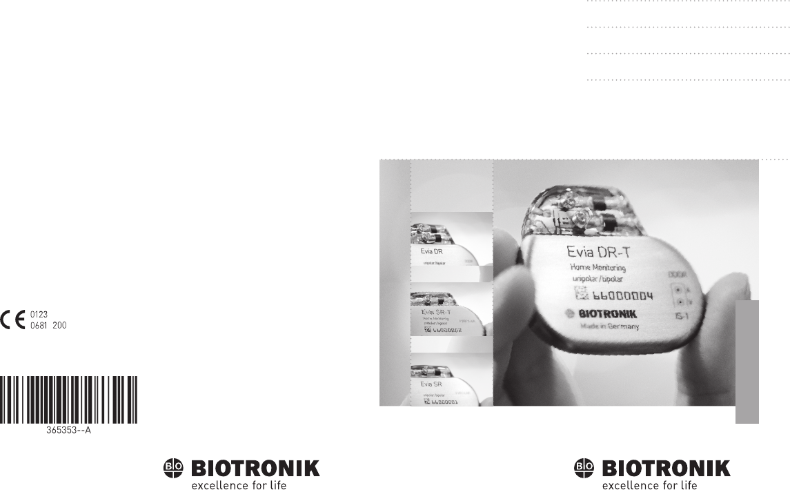
sbiotronik
Evia DR-T, DR, SR-T, SR
Pacemaker
Bradycardia therapy
Technical manual for the implant
Doc. Id.: 365353-A
Index 365353-ATechnical manual for the implantEvia DR-T, DR, SR-T, SR

2

3Table of Contents
Table of Contents
Table of Contents
Product Description. . . . . . . . . . . . . . . . . . . . . . . . . . . . . . . . . . . . . . . . . . . . 5
Intended Medical Use . . . . . . . . . . . . . . . . . . . . . . . . . . . . . . . 5
System Overview . . . . . . . . . . . . . . . . . . . . . . . . . . . . . . . . . . . 6
Implant Variants and NBG Codes . . . . . . . . . . . . . . . . . . . . . . 8
Diagnostic and Therapy Functions . . . . . . . . . . . . . . . . . . . . . 9
Scope of Delivery . . . . . . . . . . . . . . . . . . . . . . . . . . . . . . . . . . 11
General Safety Instructions . . . . . . . . . . . . . . . . . . . . . . . . . . . . . . . . . . . . 13
Possible Medical Complications. . . . . . . . . . . . . . . . . . . . . . 13
Possible Technical Complications . . . . . . . . . . . . . . . . . . . . 14
Possible Electromagnetic Complications . . . . . . . . . . . . . . 15
Possible Risks . . . . . . . . . . . . . . . . . . . . . . . . . . . . . . . . . . . . 16
Prior to Implantation. . . . . . . . . . . . . . . . . . . . . . . . . . . . . . . . . . . . . . . . . . 17
Indications and Contraindications . . . . . . . . . . . . . . . . . . . . 17
Ambient Conditions . . . . . . . . . . . . . . . . . . . . . . . . . . . . . . . . 18
Sterility . . . . . . . . . . . . . . . . . . . . . . . . . . . . . . . . . . . . . . . . . . 19
Preparing the Implantation. . . . . . . . . . . . . . . . . . . . . . . . . . 20
Implantation . . . . . . . . . . . . . . . . . . . . . . . . . . . . . . . . . . . . . . . . . . . . . . . . . 21
Implanting. . . . . . . . . . . . . . . . . . . . . . . . . . . . . . . . . . . . . . . . 21
Connecting PM Leads . . . . . . . . . . . . . . . . . . . . . . . . . . . . . . 22
Precautionary Measures while Programming . . . . . . . . . . 24
After Implantation . . . . . . . . . . . . . . . . . . . . . . . . . . . . . . . . . . . . . . . . . . . 27
Follow-up . . . . . . . . . . . . . . . . . . . . . . . . . . . . . . . . . . . . . . . . 27
Notes for the Physician . . . . . . . . . . . . . . . . . . . . . . . . . . . . . 28
Replacement Indications. . . . . . . . . . . . . . . . . . . . . . . . . . . . 29
Explantation and Implant Replacement. . . . . . . . . . . . . . . . 31

4Table of Contents
Parameters. . . . . . . . . . . . . . . . . . . . . . . . . . . . . . . . . . . . . . . . . . . . . . . . . . 33
Pacing Modes . . . . . . . . . . . . . . . . . . . . . . . . . . . . . . . . . . . . . 33
Timing DR(-T) . . . . . . . . . . . . . . . . . . . . . . . . . . . . . . . . . . . . . 34
Timing SR(-T) . . . . . . . . . . . . . . . . . . . . . . . . . . . . . . . . . . . . . 37
Pacing and Sensing DR(-T) . . . . . . . . . . . . . . . . . . . . . . . . . 38
Pacing and Sensing SR(-T) . . . . . . . . . . . . . . . . . . . . . . . . . . 40
Rate Adaptation . . . . . . . . . . . . . . . . . . . . . . . . . . . . . . . . . . . 41
Preset Programs DR(-T) . . . . . . . . . . . . . . . . . . . . . . . . . . . 42
Preset Programs SR(-T) . . . . . . . . . . . . . . . . . . . . . . . . . . . . 44
Tolerances of Parameter Values . . . . . . . . . . . . . . . . . . . . . 45
Technical Data . . . . . . . . . . . . . . . . . . . . . . . . . . . . . . . . . . . . . . . . . . . . . . . 47
Mechanical Characteristics . . . . . . . . . . . . . . . . . . . . . . . . . 47
Electrical Characteristics . . . . . . . . . . . . . . . . . . . . . . . . . . . 48
Battery Data . . . . . . . . . . . . . . . . . . . . . . . . . . . . . . . . . . . . . . 49
Country-Related Information . . . . . . . . . . . . . . . . . . . . . . . . 51
Legend for the Label . . . . . . . . . . . . . . . . . . . . . . . . . . . . . . . 52

5
1 Product Description
Product Description1365353-ATechnical manual for the implan tEvia DR-T, DR, SR-T, SR
Intended Medical Use
Intended use Evia is a family of implantable pacemakers that may be implanted for all bradycar-
dia arrhythmia indications. The primary objective of the therapy consists of improv-
ing patients' symptoms that can be clinically manifested.
The implantation of the pacemaker is a symptomatic therapy with the following
objective:
• Compensation of bradycardia by atrial, ventricular, or AV sequential pacing
Diagnosis and
therapy forms
The cardiac rhythm is automatically monitored and bradycardia arrhythmias are
treated. All major therapeutic approaches from the field of cardiology and electro-
physiology are unified in the Evia family.
BIOTRONIK Home Monitoring® enables physicians to perform therapy manage-
ment any time.
Required expertise In addition to having basic medical knowledge, the user must be thoroughly famil-
iar with the operation of an implant system. Only qualified medical specialists hav-
ing the special knowledge required for the proper use of implants are permitted to
use them. If users do not possess this knowledge, they must be trained accordingly.

6Product Description
System Overview
Parts The implant system consists of the following parts:
• Implant with connections for unipolar or bipolar sensing and pacing
• Suitable leads and approved accessories
• Programmer
• Current implant programs
Implant The implant's housing is made of biocompatible titanium, welded from outside and
thus hermetically sealed. The ellipsoid shape facilitates ingrowth into the pectoral
muscle area.
The housing serves as an antipole in the case of unipolar lead configuration.
BIOTRONIK provides silicone-coated implants to avoid muscle twitching near the
implanted pacemaker in the case of unipolar pacing.
The labeling provides information about the implant type and arrangement of the
connections.
Leads The leads are sheathed with biocompatible silicone. They can be flexibly maneu-
vered, are long-term stable, and are equipped for active or passive fixation. They
are implanted using a lead introducer set. Some leads are coated with polyurethane
to increase the sliding properties of the lead.
The coating of steroid-eluting leads reduces inflammatory processes. The fractal
design of the leads provides for low pacing thresholds, high pacing impedance, and
a low risk of oversensing.
Programmer The transportable programmer is used to transfer the appropriate implant pro-
gram to the implant. In addition to this, the programmer is used for interrogation
and storage of data from the implant. And it acts as an ECG and IEGM monitor with
Miniclinic.
The programmer communicates with the implant via the programming head. The
operation module of the programmer has a TFT touch screen with color display, on
which the ECG, IEGM, marker and functions are shown simultaneously.
The programmer has, among others, the following functions:
• Perform all tests during follow-up
• Display and print real-time and saved IEGMs with annotated markers
• Determine the pacing threshold

7Product Description
BIOTRONIK
Home Monitoring®
In addition to effective pacing therapy, BIOTRONIK provides a complete therapy
management system:
• With Home Monitoring, diagnostic and therapeutic information and technical
data are sent via an antenna in the implant header to a mobile or stationary
transmitter. The encrypted data are sent from the transmitter to the
BIOTRONIK Service Center via the cellular phone network.
• The received data are deciphered and evaluated. Each physician can set the
criteria for evaluation to be used for each patient and can configure the time of
notification via fax, SMS or E-mail.
• A clear overview of the analysis results is displayed for the attending physicians
on the protected Internet platform HMSC (Home Monitoring Service Center).
• Data transmission from the implant is performed on a daily basis with the trend
message. Depending on the transmitter used, these data are passed on imme-
diately or, if the data is normal, it is collected for up to 2 weeks. If certain events
occur in the patient's heart or in the implant itself, an event message is sent.
Additionally, patients can send a patient message by applying the magnet.
Technical manuals The following technical manuals provide information about usage of the implant
system:
• Technical manual for the implant
• Technical manual for the programmer
• User manual for the implant program:
— As a help function in the user interface
— As a file on CD
• Technical manual for the leads

8Product Description
Implant Variants and NBG Codes
Evia family The following implant variants are available:
NBG-Code for Evia DR(-T) The NBG code for dual-chamber implants is DDDR:
NBG-Code for Evia SR(-T) The NBG code for single-chamber implants is AAIR or VVIR:
Implant type Variant with
Home Monitoring Variant without
Home Monitoring
Dual-chamber Evia DR-T Evia DR
Single-chamber Evia SR-T Evia SR
Note: The setting of the pacing mode depends on the individual diagnosis; the
modes are listed in the section pertaining to adjustable parameters.
D Pacing in both chambers
D Sensing in both chambers
D Pulse inhibition and pulse triggering
R Rate adaptation
A/V Pacing in one chamber
A/V Sensing in one chamber
I Pulse inhibition in A/V
R Rate adaptation

9Product Description
Diagnostic and Therapy Functions
General overview All the systems have extensive features that allow quick diagnosis and delivery of
safe therapy for bradycardia conditions.
• Automatic functions make it easy and fast to implant, configure, and check the
pacemaker.
• Auto-initialization after implantation: the implant automatically detects the
implanted leads, sets the polarity and activates the automatic functions after
10 min.
Diagnostic functions • Data from the last 10 interrogations and follow-ups are recorded as well as
arrhythmia episodes; they are stored together with other data to assess
patients and the state of the implant at any time.
• Automatic below-threshold impedance measurement is performed in the
implant independent of the pacing pulse in order to check the lead for proper
functioning.
• When performing follow-ups using the programmer, the IEGM is indicated with
markers after applying the programming head during the test procedure.
Antibradycardia pacing • Sensing: the amplitudes of the P and R waves are measured in the implant fully
automatically to record varying amplitudes. The sensitivity for the atrium and
ventricle is adapted automatically on an ongoing basis. The measurement data
are averaged and the trend can be displayed.
• Thresholds: atrial as well as ventricular pacing thresholds are automatically
determined in the implant. Active capture control is used to set the pacing
amplitudes so that pacing is performed with the optimum atrial and ventricular
amplitude for the patients with each change of the pacing threshold.
• Timing: pacing is particularly checked in the atrium by automatic adaptation
of the atrial refractory period to avoid pacemaker-induced tachycardia.
(Auto PVARP function: automatic postal-atrial refractory period)
• Additional, special form of rate adaptation: an increased cardiac output require-
ment is detected using physiological impedance measurement. The measuring
principle is based on contractile changes (ionotropy) of the myocardium
(CLS function: Closed Loop Stimulation). The suitable rate adaptation is auto-
matically initialized and optimized in CLS mode.
• Ventricular pacing suppression: unnecessary ventricular pacing is avoided by
promoting intrinsic conduction (Vp suppression function). The implant can
adapt itself to conduction changes. In the case of intrinsic conduction, the
implant switches to a mode similar to AAI.

10 Product Description
Home Monitoring The implant automatically sends information to the transmitter once a day. Addi-
tionally, the test messages can be initiated using the programmer. Important med-
ical information include, among others, the following:
• Ongoing atrial and ventricular arrhythmia
• Parameters relevant to leads in the atrium and ventricle: thresholds, sensing
amplitudes, impedances
• Current statistics on bradycardia therapy
• Individually adjustable remote interrogation messages which enhance the
standard message with additional information relevant for follow-up
• IEGM online HD® with up to 3 channels in high definition with markers for RA
and RV, which each include the intrinsic rhythm and sequences with encour-
aged sensing and encouraged pacing
• Sending of these IEGM recordings with remote interrogation messages
• Test message triggered by the programmer to immediately check the Home
Monitoring function including notification of the physician

11 Product Description
Scope of Delivery
Standard The storage package includes the following:
• Implant in sterile packaging
• Patient's manual
• Serial number label
• Patient ID card
• Warranty card
• Technical manual
The sterile container contains the following:
• Implant
• Screwdriver
Order numbers Evia The implants can be obtained as follows:
Accessories All BIOTRONIK products correspond to the requirements of the
EC Directive 90/385/EEC:
• BIOTRONIK leads
• BIOTRONIK programming and monitoring devices
• Permanent magnet
• For Home Monitoring: BIOTRONIK transmitters
Implant Order number: uncoated Order number: coated
DR-T 359529 359530
DR 359524 359528
SR-T 359533 359534
SR 359531 359532

12 Product Description

13
2 General Safety Instructions
General Safety Instructions2365353-ATechnical manual for the im plantEvia DR-T, DR, SR-T , SR
Possible Medical Complications
General information
on medical complications
Complications for patients and implant systems generally recognized among prac-
titioners also apply to BIOTRONIK implants.
• Normal complications may include fluid accumulation within the implant
pocket, infections, or tissue reactions. Primary sources of complication infor-
mation include current scientific and technological knowledge.
• It is impossible to guarantee the efficacy of antitachycardia therapy, even if the
programs have proven successful during tests or subsequent electrophysiolog-
ical examinations. In rare cases the set parameters may become ineffective. In
particular it cannot be excluded that tachyarrhythmias be induced.
Skeletal myopotentials Bipolar sensing and control of sensitivity are adapted by the implant to the rate
spectrum of intrinsic events so that skeletal myopotentials are usually not sensed.
Skeletal myopotentials can nonetheless be sensed as intrinsic events especially
with a unipolar configuration and, depending on the interference pattern, may
cause inhibition or antiarrhythmia therapy.
Nerve and
muscle stimulation
An implant system consisting of a unipolar lead and an uncoated implant may
result in undesirable pacing of the diaphragm in the case of an initial or permanent
high setting of the pacing amplitude.
• BIOTRONIK also provides coated implants.

14 General Safety Instructions
Possible Technical Complications
Technical malfunctions Technical implant malfunctions cannot entirely be excluded. Possible causes can
include the following:
• Lead dislocation
• Lead fracture
• Insulation defects
• Implant component failures
• Battery depletion

15 General Safety Instructions
Possible Electromagnetic Complications
Electromagnetic
interference (EMI)
Any implant can be sensitive to interference, for example, when external signals
are sensed as intrinsic rhythm or if measurements prevent rate adaptation.
• BIOTRONIK implants have been designed so that their susceptibility to EMI is
minimal.
• Due to the intensity and variety of EMI, there is no guarantee for safety. It is gen-
erally assumed that EMI produces only minor symptoms in patients - if any.
• Depending on the pacing mode and the type of interference, sources of interfer-
ence may lead to pulse inhibition or triggering, an increase in the sensor-
dependent pacing rate or fixed-rate pacing.
• Under unfavorable conditions, for example during diagnostic or therapeutic
procedures, the interference sources may induce such a high level of energy
into the pacing system that the implant or cardiac tissue around the lead tip is
damaged.
Implant behavior
in case of EMI
Upon exceeding the interference rate, the implant switches to another pacing
mode. Depending on whether the interference occurs in one chamber or both
chambers, the implant switches to the A00(R), V00(R) or D00(R) mode for the dura-
tion of the interference.
Static magnetic fields The Reed contact in the pacemaker closes beginning at a field strength of 1.5 tesla.

16 General Safety Instructions
Possible Risks
Risky diagnostic and
therapeutic procedures
If electrical current from an external source is conducted through the body for diag-
nostic or therapeutic purposes, then the implant can be subjected to interference
and the patient placed at risk. Therefore the following always applies:
• Monitor the patient.
External defibrillation The implant is protected against the energy that is normally induced by external
defibrillation. Nevertheless, any implanted device may be damaged by external
defibrillation. Specifically, the current induced in the implanted leads may result in
necrotic tissue formation close to the electrode/tissue interface. As a result, sens-
ing properties and pacing thresholds may change.
• Place adhesive electrodes anterior-posterior or perpendicular to the axis
formed by the implant to the heart at least 10 cm away from the device and from
implanted leads.
Contraindicated procedures The following procedures are contraindicated:
• Therapeutic ultrasound and diathermy: damage to the patient via excess warm-
ing of body tissue near the implant system
• Transcutaneous electrical nerve stimulation (TENS)
• Lithotripsy
• Electrocautery and high-frequency surgery: damage to the patient via the
induction of arrhythmia or ventricular fibrillation
• Hyperbaric oxygen therapy
• Applied pressures higher than normal pressure
Magnetic resonance
imaging
Magnetic resonance imaging is contraindicated due to the associated magnetic flux
density: damage or destruction of the implant system by strong magnetic interac-
tion and damage to the patient by excessive warming of the body tissue in the area
surrounding the implant system.
• Under certain conditions one can perform special measures with magnetic res-
onance imaging to protect the patient and implant.
Therapeutic
ionizing radiation
Radiation can cause latent damage. This damage cannot be recognized immedi-
ately. Therefore, the following applies to X-ray diagnosis and radiation therapy:
• Sufficiently shield implant against radiation.
• After applying radiation, double-check the implant system to make sure it is
functioning properly.

17
3 Prior to Implantation
Prior to Implantation3365353-ATechnical manual for the impla ntEvia DR-T, DR, SR-T , SR
Indications and Contraindications
Guidelines of
cardiologic societies
Generally approved differential diagnostics methods, indications, and recommen-
dations for pacemaker therapy apply to BIOTRONIK implants.
The guidelines provided by cardiology associations offer decisive information.
Indications We recommend observing the indications published by the German Cardiac Society
(Deutsche Gesellschaft für Kardiologie, Herz- und Kreislaufforschung) and the ESC
(European Society of Cardiology). Likewise those published by the Heart Rhythm
Society (HRS), the American College of Cardiology (ACC), the American Heart Asso-
ciation (AHA) as well as other national cardiology associations.
Contraindications No contraindications are known for the implantation of multiprogrammable and
multifunctional single-chamber or dual-chamber implants, provided differential
diagnostics precedes implantation according to the appropriate guidelines and no
modes or parameter combinations are configured which pose a risk to the patient.
Note: The compatibility and effectiveness of parameter combinations must be
checked after programming.

18 Prior to Implantation
Ambient Conditions
Temperature Extremely low and high temperatures affect the service time of the battery in the
implant.
• The following temperatures are permitted for transport, storage, and use:
– 10°C to 45°C (50°F to 113°F)
Storage location • Implants are not to be stored close to magnets or sources of electromagnetic
interference.
Storage period The duration of storage affects the service time of the battery of the implant
(see battery data).

19 Prior to Implantation
Sterility
Delivery The implant and the accessories have been gas sterilized. Sterility is guaranteed
only if the plastic container and quality control seal have not been damaged.
Sterile container The implant and accessories are packaged respectively in two separately sealed
plastic containers. The inner plastic container is also sterile on the outside so that
it can be transferred in a sterile state during implantation.
Single use only The implant and the screwdriver are only intended for one-time use.
• Do not use if package is damaged.
• Do not resterilize.
• Do not reuse.
20 Prior to Implantation
Preparing the Implantation
Have parts ready • Ensure that sterile spare parts are available for all parts that are to be
implanted.
• Only use products that correspond to the requirements of the
EC Directive 90/385/EEC:
— BIOTRONIK implant and blind plugs
— BIOTRONIK leads and lead introducer
— BIOTRONIK programmer with approved cable and adapter accessories
— External multi channel ECG recorder
— External defibrillator and paddles or adhesive electrodes
Unpacking the implant Proceed as follows:
WARNING
Inadequate therapy due to defective implant
If an unpacked implant is dropped on a hard surface during handling, electronic
parts could be damaged.
• Use a replacement implant.
• Send the damaged implant to BIOTRONIK.
1 Peel off the sealing paper of the outer plastic container at the marked
position in the direction indicated by the arrow.
The inner plastic container may not come into contact with persons
who have not sterilized their hands or gloves, nor with non-sterile
instruments.
2 Use the gripping tab on the inner plastic container to remove it from
the outer plastic container.
3 Peel off the sealing paper of the sterile inner plastic container at the
marked position in the direction indicated by the arrow.
Note: The implant is disabled on delivery and can be implanted immediately after
unpacking without manual activation.

21
4 Implantation
Implantation4365353-ATechnical manual for the implantEvi a DR-T, DR, SR-T, SR
Implanting
Implantation site In general the pacemaker is implanted subcutaneously or subpectorally on the
right depending on the lead configuration as well as the anatomy of the patient.
Sequence Proceed as follows:
1 Shape the implant pocket and prepare the vein.
2 Implant the leads and perform measurements.
3 Connect implant and leads.
The implant starts auto-initialization on its own.
4 Insert the implant.
5 Guide the fixation suture through the opening in the header and fixate
the implant in the prepared pocket.
6 Close the implant pocket.
7 Prior to testing and configuration, wait for the successful completion
of automatic implant initialization.
Note: If necessary, the implant can also be programmed before or during auto-
initialization.
22 Implantation
Connecting PM Leads
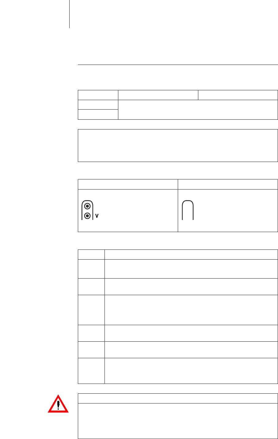
Connection options BIOTRONIK pacemakers are designed for leads with unipolar or bipolar IS-1 con-
nection. A unipolar or bipolar lead can be connected to Evia for sensing and pacing:
Connection schemes Connection scheme for dual-chamber and single-chamber implants:
Connecting the lead
connector to the implant
Proceed as follows:
DR-T and DR SR-T and SR
Atrium IS-1 unipolar or bipolar
Ventricle
Note: Use only adapters approved by BIOTRONIK for leads with different connec-
tions.
• If you have any questions concerning the compatibility of other manufactur-
ers' leads, please contact BIOTRONIK.
DR-T and DR SR-T and SR
DDDR
A
IS-1
VVIR/AAIR
IS-1
1 Disconnect stylets and insertion aids from the lead connector.
2 • Connect the unipolar or bipolar IS-1 lead connector atrium to A.
• Connect the unipolar or bipolar IS-1-lead connector ventricle to V.
3 Push the lead connector into the header without bending the conduc-
tor until the connector tip becomes visible behind the set screw block.
4 If the lead connector cannot be inserted completely, the set screw
may be protruding into the cavity of the set screw block. Carefully
loosen the set screw without completely unscrewing it, so that it does
not become tilted upon retightening.
5 Use the screwdriver to perpendicularly pierce through the slitting in
the center of the silicone plug until it reaches the set screw.
6 Turn the set screw clockwise until the torque control starts (you will
hear a clicking sound).
7 Carefully withdraw the screwdriver without retracting the set screw.
• When you withdraw the screwdriver, the silicone plug automati-
cally seals the lead connection safely.
WARNING
Short circuit due to open lead connections
Open, and thus not electrolyte-tight, IS-1 connections may cause undesired
current flow to the body and penetration of bodily fluid into the implant.
• Close IS-1 connections that are not in use with IS-1 blind plugs.

23 Implantation
Auto-initialization Auto-initialization begins automatically once the first connected lead is detected.
Auto-initialization is terminated 10 minutes after connection of the first lead. If no
other program has been transferred in the meantime, the implant subsequently
works with active automatic functions in the standard program.
Manual setting of the lead polarity or measurement of lead impedances is not
necessary.
Behavior during
auto-initialization
• During reprogramming: auto-initialization is canceled and the transferred
program is immediately active.
• During testing: auto-initialization is subsequently continued.
• During transmission of a permanent program: auto-initialization is terminated
and the transferred program is active.
Note: After auto-initialization, all parameters are activated as in the standard
program with the following exceptions:
• DDD-CLS
• VVI
• The automatically determined lead configuration (unipolar or bipolar) is set.

24 Implantation
Precautionary Measures while Programming
Checking the
implant system
• After auto-initialization perform follow-up to see if the implant system is func-
tioning properly.
• Perform a pacing threshold test to determine the pacing threshold.
Monitoring the patient The patient could be subjected to critical states if, for example, inadequate param-
eters are set or due to telemetry interference during a temporary program.
• Continuously monitor the ECG and the patient's condition.
• Remove the programming head to a distance of at least 30 cm and the perma-
nent program will be reactivated immediately.
Manually setting
lead polarity
Due to the risk of an entrance/exit block, bipolar lead polarity (sensing/pacing)
should only be set if bipolar leads are implanted.
Setting the
triggered pacing mode
Triggered pacing modes perform pacing regardless of intrinsic cardiac events. To
prevent undersensing due to electromagnetic interference in special cases, a trig-
gered pacing mode can be displayed.
Avoiding
asynchronous pacing
High pacing rates with long refractory periods (a/v) can lead to intermittent, asyn-
chronous pacing. Such programming can be contraindicated in some cases.
Setting sensing • In order to avoid errors in manually set parameters, set automatic sensitivity
control.
• Unsuitable far-field protection can hinder pacemaker sensing (undersensing).
Setting the sensitivity A value set to < 2.5 mV/unipolar for implant sensitivity may result in noise caused
by electromagnetic fields.
• Therefore, it is recommended that a value of ≥ 2.5 mV/unipolar be set according
to paragraph 28.22.1 of the EN 45502-2-1 standard. Setting sensitivity values
< 2.5 mV/unipolar requires explicit clinical need. Values like this can only be set
and retained with physician supervision.
Preventing implant-induced
complications
• Measure the retrograde conduction time.
• If the function is not yet automatically set: activate PMT protection.
• Set the VA criterion.

25 Implantation
Information on
magnet response
Applying a magnet or the programming head can result in an unphysiological
rhythm change and asynchronous pacing. The magnet response is set as follows in
the standard program of BIOTRONIK pacemakers:
• Asynchronous: for the duration of the magnet application – mode D00 (possibly
V00 / A00) without rate adaptation; magnet rate: 90 ppm
• Automatic: for 10 cycles – mode D00, subsequently mode DDD without rate
adaptation; magnet rate: 10 cycles with 90 ppm, subsequently set basic rate
• Synchronous: mode DDD without rate adaptation; magnet rate: set basic rate
Preventing conduction
of atrial tachycardia
to the ventricle
• If the function is not yet automatically set: activate Mode Switching for indicated
patients.
• Set the upper rate and the refractory periods to prevent abrupt ventricular rate
switching.
• Prefer Wenckebach response and avoid 2:1 behavior.
• Set all parameters so as to prevent constant changing between atrial and ven-
tricular-controlled modes.
If an ICD is implanted
at the same time,
do not permit unipolar pacing
If an ICD is implanted in addition to a pacemaker and a lead failure occurs, it is pos-
sible to switch to unipolar pacing after a pacemaker reset or using the automatic
lead check. The ICD could therefore falsely inhibit or trigger tachyarrhythmia ther-
apy activity.
• Unipolar leads are not permitted in this configuration.
Consider power consumption
and service time
The pacemaker permits programming of high pulse amplitudes with long pulse
widths at high rates to be able to adequately treat even rare diagnoses. In combina-
tion with low lead impedance, this results in a very high level of power consumption.
• When programming large parameter values, take into account that the battery
depletion indicator ERI will be activated very early because the service time of
the battery may be reduced to less than 1 year.
Note: See information pertaining to replacement indications for magnet behavior
at ERI.

26 Implantation

27
5 After Implantation
After Implantation 5365353-ATechnical manual for the implan tEvia DR-T, DR, SR-T, SR
Follow-up
Follow-up intervals Follow-ups must be performed at regular agreed intervals.
• Follow-ups with the programmer should take place in intervals between
6 to 12 months considering the expected service life of the implant.
Follow-up with
the programmer
Proceed as follows:
1 Record and evaluate the external ECG.
2 Check the pacing function.
3 Interrogate the implant.
4 Evaluate the status and automatically measured follow-up data.
5 Possibly evaluate statistics and Holter/IEGM recording.
6 Manually perform standard tests if necessary.
7 Possibly customize program functions and parameters.
8 Transmit the program permanently to the implant.
9 Print and document follow-up data (print report).
10 Finish the follow-up for this patient.

28 After Implantation
Notes for the Physician
Notes for patients A patient brochure and a patient ID card are supplied with the device.
• Provide the patient with the patient brochure and patient ID card.
• Draw the patient's attention to prohibitory signs: places with prohibitory signs
must be avoided.
Possible sources
of interference
Interference can be caused by, among others, the following:
• Household appliances
• Safety locks or anti-theft installations
• Strong electromagnetic fields
• Cellular phones and transmitters
Using cellular phones Electromagnetic interference has a temporary effect only. Generally, BIOTRONIK
implant functions return to normal when the respective cellular phone is removed
from the proximity of the implant.
• Patients are advised to hold cellular phones to the ear opposite the side on
which the device is implanted. Cellular phones should also be kept at least
15 cm away from the implant. If the power of transmission is greater than
3 watts, they must be kept at least 30 cm away.
• Some cellular phones emit signals when in stand-by mode, i.e., even when not
in use. Therefore, patients should not carry a cellular phone in a chest pocket
or attached to a belt or within a radius of 15 cm from the implant.
Magnet application
by patients
If patients are to be entrusted with magnet application, the synchronous magnet
mode has to have been programmed. Patients should also know the following:
• When may the magnet be used?
In cases of severe dizziness and indisposition
• How long is the magnet placed on the pacemaker?
1 to 2 seconds
• What happens when the magnet is applied?
The IEGM of the last 10 seconds is stored.
• What has to happen after magnet application?
The patient has to contact the physician for a check-up

29 After Implantation
Replacement Indications
Pacemaker operational
status indications
The time span from the beginning of service (BOS) to elective replacement indica-
tion (ERI) is determined by, among others, the following:
• Battery capacity
• Lead impedance
• Pacing program
• Pacing to inhibition ratio
• Pacemaker circuit properties
The following are the defined pacemaker operational statuses:
ERI activation ERI detection is automatically activated after the following events:
• Successful auto-initialization
• Storage for longer than 24 months
ERI display ERI is displayed as follows:
• By a defined decrease in the basic rate as well as the magnet rate
• After interrogation of the pacemaker
Change of the pacing mode
with ERI
From dual-chamber modes, the pacemaker switches to single-chamber pacing.
This replacement mode depends on the programmed mode and is displayed on the
programmer.
Deactivated functions
with ERI
The following functions are deactivated:
• Atrial pacing
• Night program
• Rate adaptation
• Atrial and ventricular active capture control
• Rate fading
• Atrial overdrive pacing
• IEGM recordings
• Statistics
• Home Monitoring
• Rate hysteresis
• Ventricular pacing suppression
BOS Beginning of Service Battery is in good condition; normal
follow-up.
ERI Elective Replacement
Indication
The replacement time has been reached.
The pacemaker must be replaced.
EOS End of Service End of service time with regular pace-
maker activity.

30 After Implantation
Rate decrease The decrease of basic rate and magnet rate is defined as follows:
• In the following pacing modes the pacing rate decreases by 11%: DDD(R);
DDT(R); DOO(R) VDD(R); VDI(R); VVI(R), VVT(R) AAI(R); AAT(R); AOO(R).
• In the pacing modes DDI(R) and DVI(R), only the VA interval is extended by 11%.
This reduces the pacing rate by 4.5 to 11%, depending on the configured AV
delay.
Magnet response at ERI After reaching ERI pacing is performed as follows after applying the magnet or pro-
gramming head:
Expected service time
after ERI
• The information is based on a lead impedance of 500 Ohm at 100% pacing and
the data of the battery manufacturer.
• For a lead impedance of 300 Ohm instead of 500 Ohm, these times decrease by
max. 30%.
• Parameter with high pulse energy: 110 ppm; 4.6 V; 1.5 ms; 500 Ohm
• Parameter with low pulse energy: 30 ppm; 0.2 V; 0.1 ms; 500 Ohm
• Dual-chamber implant in DDDR mode; single-chamber implant in
AAIR/VVR mode:
[in months]
Magnet mode
Cycles 1 to 10: After 10th cycle:
Automatically Asynchronous with rate at
80 ppm
Synchronous with basic rate
reduced by 4.5 to 11%
Asynchronous Asynchronous with rate at
80 ppm
Asynchronous with rate at
80 ppm
Synchronous Synchronous with basic rate
reduced by 4.5 to 11%
Synchronous with basic rate
reduced by 4.5 to 11%
ERI to EOS interval Standard program With high pulse
energy With low pulse
energy
Mean value 8 8 8
Minimum value 6 6 6

31 After Implantation
Explantation and Implant Replacement
Explantation • Disconnect the leads from the header.
• Remove the implant and, if necessary, leads using state-of-the-art technology.
• Explants are biologically contaminated and must be disposed safely due to risk
of infection.
Implant replacement • Implanted leads of a predecessor implant must be checked before they are con-
nected to a new implant.
Cremation Implants should not be cremated.
• Explant the implant before the cremation of a deceased patient.
Disposal BIOTRONIK takes back used products for the purpose of environmentally safe dis-
posal.
• Clean the explant with an at least 1% sodium-hyperchlorine solution.
• Rinse off with water.
• Fill out explantation form and send to BIOTRONIK together with the cleaned
implant.
WARNING
Interference with functioning of the implant system
If, upon replacing the implant, predecessor leads are no longer used but left in
the patient, then an additional uncontrolled current path to the heart can result.
• Insulate connections that are not used.

32 After Implantation

33
6 Parameters
Parameters6365353-ATechnical manual for the implantEvia DR-T, DR, SR-T, SR
Pacing Modes
Evia family The following pacing modes are available:
Implant type Pacing mode Standard
DR(-T) • DDD-CLS, VVI-CLS
• DDDR, DDIR, DVIR, DOOR
VDDR, VDIR, VVIR, VVTR, VOOR
AAIR, AATR, AOOR
• DDD, DDT, DDI, DVI, DOO
VDD, VDI, VVI, VVT, VOO
AAI, AAT, AOO
OFF
DDDR
SR(-T) • VVI-CLS
• VVIR, VOOR
AAIR*, AATR*, AOOR*
• VVI, VVT, VOO
AAI*, AAT*, AOO*
OFF
*depends on the programmer software
VVIR
Note: Home Monitoring is possible in all pacing modes.

34 Parameters
Timing DR(-T)
Basic rate day/night
Rate hysteresis
AV delay
AV hystereses
Parameter Range of values Standard
Basic rate 30 ... (1) ... 90 ... (2) ... 122 ... (3) ... 140
... (5) ... 200 ppm
60 ppm
Night rate OFF;
30 ... (1) ... 90 ... (2) ... 122 ... (3) ... 140
... (5) ... 200 ppm
OFF
Night begins 00:00 ... (10 min) ... 23:59 hh:mm 22:00 hh:mm
Night ends 00:00 ... (10 min) ... 23:59 hh:mm 06:00 hh:mm
Parameter Range of values Standard
Rate hysteresis OFF;
-5 ... (-5) ... -90 ppm
OFF
Repetitive hysteresis OFF; 1 ... (1) ... 15 OFF
Scan hysteresis OFF; 1 ... (1) ... 15 OFF
Parameter Range of values Standard
AV delay Low; medium; high; fixed;
individual
Low
AV delay 15 ... (5) ... 350 ms
(in 6 rate ranges)
180 ms
Sense compensation OFF;
-10 ... (5) ... -120 ms
-45 ms
AV safety delay 100 ms 100 ms
Parameter Range of values Standard
AV hysteresis mode OFF;
Negative, low; medium; high;
IRSplus
OFF
Positive repetitive
AV hysteresis
OFF;
1 ... (1) ... 10
OFF
Negative repetitive
AV hysteresis
OFF;
1 ... (1) ... 15 ... (5) ... 100 ... (10)
... 180
OFF
AV scan hysteresis OFF;
1 ... (1) ... 10
OFF

35 Parameters
Ventricular
pacing suppression
Upper rate
Mode switching
Refractory periods
Parameter Range of values Standard
Vp suppression OFF; ON OFF
Pacing suppression after
consecutive Vs
1 ... (1) ... 8 6
Pacing supports after
X-out-of-8 cycles
1; 2; 3; 4 3
Parameter Range of values Standard
Upper rate 90 ... (10) ... 200 ppm 130 ppm
Atrial upper rate OFF;
240 ppm
240 ppm
Parameter Range of values Standard
Mode switching OFF; ON ON
Intervention rate 100 ... (10) ... 250 ppm 160 ppm
Switch to (mode) DDI;
DDI(R) when permanent DDD(R)
VDI;
VDI(R) when permanent VDD(R)
DDIR
VDIR
Onset criterion 3 ... (1) ... 8 5
Resolution criterion 3 ... (1) ... 8 5
Change of the basic rate
with mode switching
OFF;
+5 ... (5) ... +30 ppm
+10 ppm
Rate stabilization with
mode switching
OFF; ON OFF
Parameter Range of values Standard
Atrial refractory period AUTO AUTO
Atrial refractory period in
the modes AAI(R); AAT(R);
DDT
300 ... (25) ... 775 ms 350 ms
PVARP AUTO;
175 ... (5) ... 600 ms
AUTO
PVARP after PVC PVARP + 150 ms (max: 600 ms)
is automatically programmed
400 ms
Ventricular
refractory period
200 ... (25) ... 500 ms 250 ms

36 Parameters
Blanking periods
PMT protection
Parameter Range of values Standard
Far-field protection after Vs100 ... (10) ... 220 ms 100 ms
Far-field protection after Vp100 ... (10) ... 220 ms 150 ms
Ventricular blanking after Ap30 ... (5) ... 100 ms 30 ms
Parameter Range of values Standard
PMT detection/termination OFF; ON ON
VA criterion 250 ... (10) ... 500 ms 350 ms

37 Parameters
Timing SR(-T)
Basic rate day/night
Rate hysteresis
Upper rate
Refractory period
Parameter Range of values Standard
Basic rate 30 ... (1) ... 90 ... (2) ... 122 ... (3) ... 140
... (5) ... 200 ppm
60 ppm
Night rate OFF
30 ... (1) ... 90 ... (2) ... 122 ... (3) ... 140
... (5) ... 200 ppm
OFF
Night begins 00:00 ... (10 min) ... 23:59 hh:mm 22:00 hh:mm
Night ends 00:00 ... (10 min) ... 23:59 hh:mm 06:00 hh:mm
Parameter Range of values Standard
Rate hysteresis OFF
-5 ... (-5) ... -90 ppm
OFF
Repetitive hysteresis OFF; 1 ... (1) ... 15 OFF
Scan hysteresis OFF; 1 ... (1) ... 15 OFF
Parameter Range of values Standard
Upper rate 90 ... (10) ... 200 ppm 130 ppm
Parameter Range of values Standard
Refractory period 200 ... (25) ... 500 ms 250 ms

38 Parameters
Pacing and Sensing DR(-T)
Pulse amplitude
and pulse width
Sensitivity
Atrial capture control
Ventricular capture control
Parameter Range of values Standard
Pulse amplitude A 0.2 ... (0.1) ... 6.2; 7.5 V 3.0
Pulse width A 0.4; 0.5; 0.7; 1.0; 1.2; 1.5 ms 0.4 ms
Pulse amplitude V 0.2 ... (0.1) ... 6.2; 7.5 V 3.0 V
Pulse width V 0.4; 0.5; 0.7; 1.0; 1.2; 1.5 ms 0.4 ms
Parameter Range of values Standard
Sensitivity A AUTO
0.1 ... (0.1) ... 1.5 ... (0.5) ... 7.5 mV
AUTO
Sensitivity V AUTO
0.5 ... (0.5) ... 7.5 mV
AUTO
Parameter Range of values Standard
Atrial capture control ATM (monitoring only); OFF OFF
Min. amplitude 0.5 ... (1) ... 4.8 V 1.0 V
Threshold test start 2.4; 3.0; 3.6; 4.2; 4.8 V 3.0 V
Safety margin 0.5 ... (1) ... 1.2 V 1.0 V
Search time Interval; time of day Interval
Interval 0.1; 0.3; 1; 3; 6; 12; 24 h 24 h
Time of day 00:00 ... (15 min) ... 23:45 02:00
Parameter Range of values Standard
Ventricular capture control ON; ATM (monitoring only); OFF ON
Min. amplitude 0.7 V 0.7 V
Threshold test start 2.4; 3.0; 3.6; 4.2; 4.8 V 3.0 V
Safety margin 0.3 ... (1) ... 1.2 V 0.5 V
Search time Interval; time of day Interval
Interval 0.1; 0.3; 1; 3; 6; 12; 24 h 24 h
Time of day 00:00 ... (15 min) ... 23:45 hh:mm 02:00 hh:mm

39 Parameters
Lead configuration
IEGM recordings
Rates for statistics
Parameter Range of values Standard
Pacing polarity A Unipolar; bipolar Unipolar
Pacing polarity V Unipolar; bipolar Unipolar
Sensing polarity A Unipolar; bipolar Unipolar
Sensing polarity V Unipolar; bipolar Unipolar
Parameter Range of values
IEGM recordings 20 (quantity); each max. 10 s
Types of IEGM recordings High atrial rate (HAR)
Mode switching (MSW)
High ventricular rate (HVR)
Patient triggered (Pt.)
IEGM recording prior to event 0; 25; 50; 75; 100%
IEGM signal Filtered; unfiltered
Parameter Range of values Standard
High atrial rate (HAR) 100 ... (5) ... 250 bpm
600; 572 ... 245; 240 ms
200 bpm
300 ms
High ventricular rate (HVR) 150 ... (5) ... 200 bpm
400; 378 ... 308; 300 ms
180 bpm
333 ms
HVR counter 4; 8; 12; 16 8

40 Parameters
Pacing and Sensing SR(-T)
Pulse amplitude
and pulse width
Sensitivity
Ventricular capture control
Lead configuration
IEGM recordings
Rates for statistics
Parameter Range of values Standard
Pulse amplitude 0.2 ... (0.1) ... 6.2; 7.5 V 3.0 V
Pulse width 0.1; 0.2; 0.3; 0.4; 0.5; 0.75; 1.0; 1.25;
1.5 ms
0.4 ms
Parameter Range of values Standard
Sensitivity AUTO
0.5 ... (0.5) ... 7.5 mV
AUTO
Parameter Range of values Standard
Ventricular capture control ON; ATM (monitoring only)
OFF
ON
Min. amplitude 0.7 V 0.7 V
Threshold test start 2.4; 3.0; 3.6; 4.2; 4.8 V 3.0 V
Safety margin 0.3 ... (1) ... 1.2 V 0.5 V
Search time Interval; time of day Interval
Interval 0.1; 0.3; 1; 3; 6; 12; 24 h 24 h
Time of day 00:00 ... (15 min) ... 23:45 hh:mm 02:00 hh:mm
Parameter Range of values Standard
Pacing polarity Unipolar; bipolar Unipolar
Sensing polarity Unipolar; bipolar Unipolar
Parameter Range of values
IEGM recordings 20 (quantity); each max. 10 s
Types of IEGM recordings High rate (HR)
Patient triggered (Pt.)
IEGM recording prior to event 0; 25; 50; 75; 100%
IEGM signal Filtered; unfiltered
Parameter Range of values Standard
High rate (HR) 150 ... (5) ... 200 bpm
400; 387 ... 308; 300 ms
180 bpm
333 ms
HF counter 4; 8; 12; 16 8

41 Parameters
Rate Adaptation
Closed Loop Stimulation
rate adaptation
CLS modes:
Rate adaptation
via accelerometer
R modes:
Parameter Value range Standard
Max. CLS rate 80 ... (5) ... 160 ppm 120 ppm
CLS response Very low; low; medium; high;
very high
Medium
Resting rate control OFF;
+10 ... (10) ... +50 ppm
+20 ppm
CLS required Yes; no No
Parameter Range of values Standard
Sensor gain 1 ... 23 4
Max. activity rate 80 ... (5) ... 160 ppm 120 ppm
Automatic gain OFF; ON ON
Sensor threshold Very low; low; medium; high; very
high
Medium
Rate increase 1; 2; 4; 8 ppm/cycle 4 ppm/cycle
Rate decrease 0.1; 0.2; 0.5; 1.0 ppm/cycle 0.5 ppm/
cycle
Rate fading OFF; ON OFF

42 Parameters
Preset Programs DR(-T)
Standard and safe program Only the auto-initialization function is activated as a factory setting. All the other
functions of the standard program are deactivated.
Parameter Standard program Safe program
Mode (after auto initialization:
DDD-CLS)
DDDR VVI
Basic rate 60 ppm 70 ppm
Night program OFF OFF
Rate hysteresis OFF OFF
Upper rate 130 ppm —
Dynamic AV delay Low —
AV hysteresis OFF —
Sense compensation –45 ms —
AV safety delay 100 ms —
Far-field protection after Vs100 ms —
Far-field protection after Vp150 ms —
Ventricular blanking period after Ap32 ms —
PMT protection ON —
VA criterion 380 ms —
Magnet response AUTO AUTO
Pulse amplitude A 3.0 V —
Pulse amplitude V 3.0 V 4.8 V
Pulse width A 0.4 ms —
Pulse width V 0.4 ms 1.0 ms
Sensitivity A AUTO —
Sensitivity V AUTO 2.5 mV
Refractory period A AUTO —
Refractory period V 250 ms 300 ms
Mode switching ON —
Onset criterion 5-out-of 8 —
Resolution criterion 5-out-of 8 —
Intervention rate 160 ppm —
Switches to DDIR —
Basic rate with mode switching +10 ppm —
Rate stabilization with
mode switching
OFF —
PVARP AUTO AUTO
PVARP after PVC 400 ms —

43 Parameters
Lead configuration, automatically determined and set:
Pacing polarity Unipolar Unipolar
Sensing polarity Unipolar Unipolar
Automatic lead check A/V ON ON
Active capture control ATM OFF
IEGM recording (HAR) ON OFF
Home Monitoring OFF OFF
Parameter Standard program Safe program

44 Parameters
Preset Programs SR(-T)
Standard and safe program Only the auto-initialization function is activated as a factory setting. All the other
functions of the standard program are deactivated.
Parameter Standard program Safe program
Mode (after auto initialization: VVI) VVI VVI
In the AAI mode, the safe program is also
AAI.
Basic rate 60 ppm 70 ppm
Night program OFF OFF
Rate hysteresis OFF OFF
Magnet response AUTO AUTO
Pulse amplitude 3.0 V 4.8 V
Pulse width 0.4 ms 1.0 ms
Sensitivity AUTO 2.5 ms
Refractory period 250 ms 300 ms
Lead configuration, automatically determined and set
Pacing polarity Unipolar Unipolar
Sensing polarity Unipolar Unipolar
Automatic lead check ON ON
Active capture control ATM OFF
IEGM recording ON OFF
Home Monitoring OFF OFF

45 Parameters
Tolerances of Parameter Values
DR(-T)
Parameter Range of values Tolerance
Basic rate 30 ... 100 ppm +/-1.5 ppm
102 ... 195 ppm +/-2.0 ppm
200 ppm +0.0/-3.0 ppm
Basic interval 1000 ms +/-20 ms
Magnet rate 90 ppm +/-1.5 ppm
Magnet interval 664 ms +/-20 ms
AV delay 15 ... 350 ms +20/-5 ms
A/V pulse amplitude 0.2 V +/-0.10 V
0.3 ... 7.5 V +20/-25%
A/V pulse duration 0.1 ... 0.4 ms +/-0.04 ms
0.5 ... 1.0 ms +/-0.10 ms
1.25 ... 1.5 ms +/-0.15 ms
Sensitivity A
45502-2-1 Delta pulse
0.1 ... 0.5 mV +/-0.10 mV
0,6 ... 7.5 mV +/-20%
Sensitivity V
45502-2-1 Delta pulse
0.5 ... 7,5 mV +/-20%
Refractory period A 300 ... 775 ms +10/-30 ms
Refractory period V 200 ... 500 ms +10/-30 ms
PVARP 175 ... 600 ms +10/-30 ms
PVARP after PVC 325 ... 600 ms +10/-30 ms
Max. activity rate 80 ... 100 ppm +/-1.5 ppm
105 ... 160 ppm +/-2.0 ppm
Upper rate 90 ... 190 ppm +/-2.0 ppm
200 ppm +0/-2.0 ppm
High rate protection 200 ppm +20/-0 ppm
Lead impedance 100 ... 200 Ohm +/-50 Ohm
201 ... 2500 Ohm +/-25%

46 Parameters
SR(-T)
Parameter Range of values Tolerance
Basic rate 30 ... 100 ppm +/-1.5 ppm
102 ... 195 ppm +/-2.0 ppm
200 ppm +0.0/-3.0 ppm
Basic interval 1000 ms +/-20 ms
Magnet rate 90 ppm +/-1.5 ppm
Magnet interval 664 ms +/-20 ms
Pulse amplitude 0.2 V +/-0.10 V
0.3 ... 7.5 V +20/-25%
Pulse width 0.1 ... 0.4 ms +/-0.04 ms
0.5 ... 1.0 ms +/-0.10 ms
1.25 ... 1.5 ms +/-0.15 ms
Sensitivity
45502-2-1 Delta pulse
0.5 ... 7.5 mV +/-20%
Refractory period 200 ... 500 ms +10/-30 ms
Max. activity rate 80 ... 100 ppm +/-1.5 ppm
105 ... 160 ppm +/-2.0 ppm
High rate protection 200 ppm +20/-0 ppm
Lead impedance 100 ... 200 Ohm +/-50 Ohm
201 ... 2500 Ohm +/-25%

47
7 Technical Data
Technical Data7365353-ATechnical manual for the implantEvia DR-T, DR, SR- T, SR
Mechanical Characteristics
Measurements for
the housing
The measurements refer to the housing without header.
Radiopaque marker BIO SF
Materials in contact
with body tissue
• Housing: titanium
• Header: epoxy resin
• Sealing plug: silicone
• Coating, if applicable: silicone
Implant W x H x D [mm] Volume [cm3] Mass [g]
DR-T 53 x 44.5 x 6.5 12 25
DR 53 x 43 x 6.5 11 26
SR-T 53 x 39 x 6.5 11 24
SR 53 x 39 x 6.5 10 25
(FCC ID: QRIPRIMUS) This transmitter is authorized by rule under the Medical
Device Radiocommunication Service (in part 95 of the FCC Rules) and must not
cause harmful interference to stations operating in the 400.150-406.000 MHz band
in the Meteorological Aids (i.e., transmitters and receivers used to communicate
weather data), the Meteorological Satellite, or the Earth Exploration Satellite Ser-
vices and must accept interference that may be caused by such stations, including
interference that may cause undesired operation. This transmitter shall be used
only in accordance with the FCC Rules governing the Medical Device Radiocom-
munication Service. Analog and digital voice communications are prohibited.
Although this transmitter has been approved by the Federal Communications
Commission, there is no guarantee that it will not receive interference or that any
particular transmission from this transmitter will be free from interference.
FCC Statement
48 Technical Data
Electrical Characteristics
Components
and input values
Electrical characteristics determined at 37°C, 500 Ohm
Housing shape The implant housing has the following shape:
Electrically
conductive surface
The implant housing has the following surface:
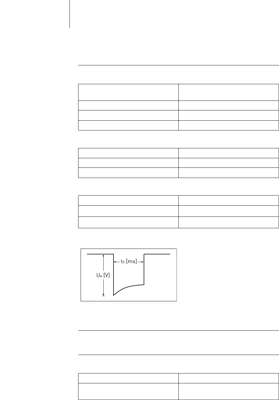
Pulse form The pacing pulse has the following form:
The pulse amplitude reaches its maximum value at the beginning of the pulse (Ua).
With increasing pacing duration (tb), the pulse amplitude is reduced dependent on
the pacing impedance.
Resistance to interference All variants of BIOTRONIK implants comply with the requirements of
prEN 45502-2-2: 2006, Section 27.5.1 at the highest sensitivity.
Telemetry Telemetry data for Home Monitoring:
Circuit Hybrid electronics with VLSI-CMOS
chip
Input impedance > 10 kOhm
Pulse form Biphasic, asymmetric
Polarity Cathodic
Implant type DR(-T), SR(-T)
Uncoated Flattened ellipsoid
Coated Ellipse
Implant type DR(-T), SR(-T)
Uncoated [cm2]33
Coated [cm2]7
Nominal carrier frequency Maximum power of transmission
403.62 MHz < 25 μW
-16 dBm

49 Technical Data
Battery Data
Battery type characteristics The following data is entered by the manufacturer:
Power consumption The implant has the following power consumption:
Average service time Average service times are precalculated using the battery manufacturer's technical
specifications, a basic rate of 60 ppm and the setting of different pulse amplitudes
and lead impedances.
Service times DR(-T) For dual-chamber implants, the following times (in years) result:
Manufacturer GREATBATCH, INC.
Clarence, NY 14031, USA LITRONIK GmbH
01796 Pirna, Germany
Battery type GB 8431 GB 2596 LiS 3150 LiS 3150M
System LiJ Ag/SVO/CFx
QMR®
LiJ LiMn02
Implant DR
SR
DR-T
SR-T
DR
SR
DR-T
SR-T
Battery voltage
at BOS
2.8 V 3.0 V 2.8 V 3.1 V
Open-circuit volt-
age
2.8 V 3.0 V 2.8 V 3.1 V
Nominal capacity 1.3 Ah 1.3 Ah 1.3 Ah 1.2 Ah
Usable capacity
until EOS
1.2 Ah 1.1 Ah 1.2 Ah 1.0 Ah
Power consumption DR(-T) SR(-T)
BOS, inhibited 6 μA 6 μA
BOS, 100% pacing 13 μA 9 μA
Amplitude Impedance
[Ohms] Pacing
10% 50% 100%
DR-T DR DR-T DR DR-T DR
1.5 V 500 19.3 17.8 17.2 15.8 15.0 13.9
1000 19.7 18.0 18.3 16.9 17.0 15.7
2.5 V 500 17.8 16.6 13.6 12.8 9.4 10.0
1000 18.8 17.4 15.3 14.9 12.5 12.7
3.0 V 500 17.3 15.8 11.8 10.9 8.5 7.8
1000 18.5 16.9 14.6 13.4 11.6 10.7
3.5 V 500 16.5 15.1 10.4 9.7 7.2 6.6
1000 18.0 16.5 13.4 12.4 10.2 9.4
5.0 V 500 12.4 12.1 5.4 6.2 3.2 3.8
1000 15.2 14.6 8.3 9.2 5.3 6.3

50 Technical Data
Service times SR(-T) For single-chamber implants, the following times (in years) result:
Shortening
of the service time
after long storage period
Depending on the storage period, the service time from the beginning of service
BOS to the replacement time ERI decreases as follows:
• After 1 year:
— DR(-T) by 6 months
— SR(-T) by 8 months
• After 1.5 years:
— DR(-T) by 9 months
— SR(-T) by 12 months
Amplitude Impedance
[Ohms] Pacing
10% 50% 100%
SR-T SR SR-T SR SR-T SR
1.5 V 500 23.3 21.3 21.7 19.8 19.9 18.3
1000 23.6 21.5 22.7 20.7 21.6 19.8
2.5 V 500 22.1 20.3 17.8 17.3 14.3 14.6
1000 22.8 21.0 20.2 19.2 17.5 17.2
3.0 V 500 21.7 19.8 16.8 15.5 13.2 12.2
1000 22.7 20.7 19.5 17.8 16.6 15.3
3.5 V 500 20.9 19.1 15.3 14.2 11.5 10.7
1000 22.3 20.3 18.4 16.9 15.1 13.9
5.0 V 500 17.2 16.3 9.1 10.1 5.7 6.8
1000 19.8 18.7 12.8 13.7 8.9 10.2

51 Technical Data
Country-Related Information
International certification Other notes specific to each country will follow in the course of international prod-
uct certification.
Industry Canada Telemetry data
• This device may not interfere with stations operating in the rate range of
400.150 - 406.000 MHz in the meteorological aids, meteorological-satellite, and
earth exploration-satellite services and must accept any interference received,
including interference that may cause undesired operation.
• This implant will be registered with Industry Canada under the following
number:
IC: 4708A-PRIMUS
• The code IC in front of the certification/ registration number only indicates that
the technical requirements for Industry Canada are met.
China The following provides information according to the ordinance no. 39 issued by the
'Ministry for Industry and Information Technology' of the People's Republic of
China pertaining to the materials which are contained in BIOTRONIK's pacemak-
ers, ICDs and external devices:
Dangerous material In PCBs In cables
Lead Pb Yes (soldering agent) Yes
Mercury Hg No No
Cadmium Cd No No
Chrome compounds Cr6+ No No
Polybrominated biphenyls PBB No No
Polybrominated diphenyl ether PBDE No No
25
52 Technical Data
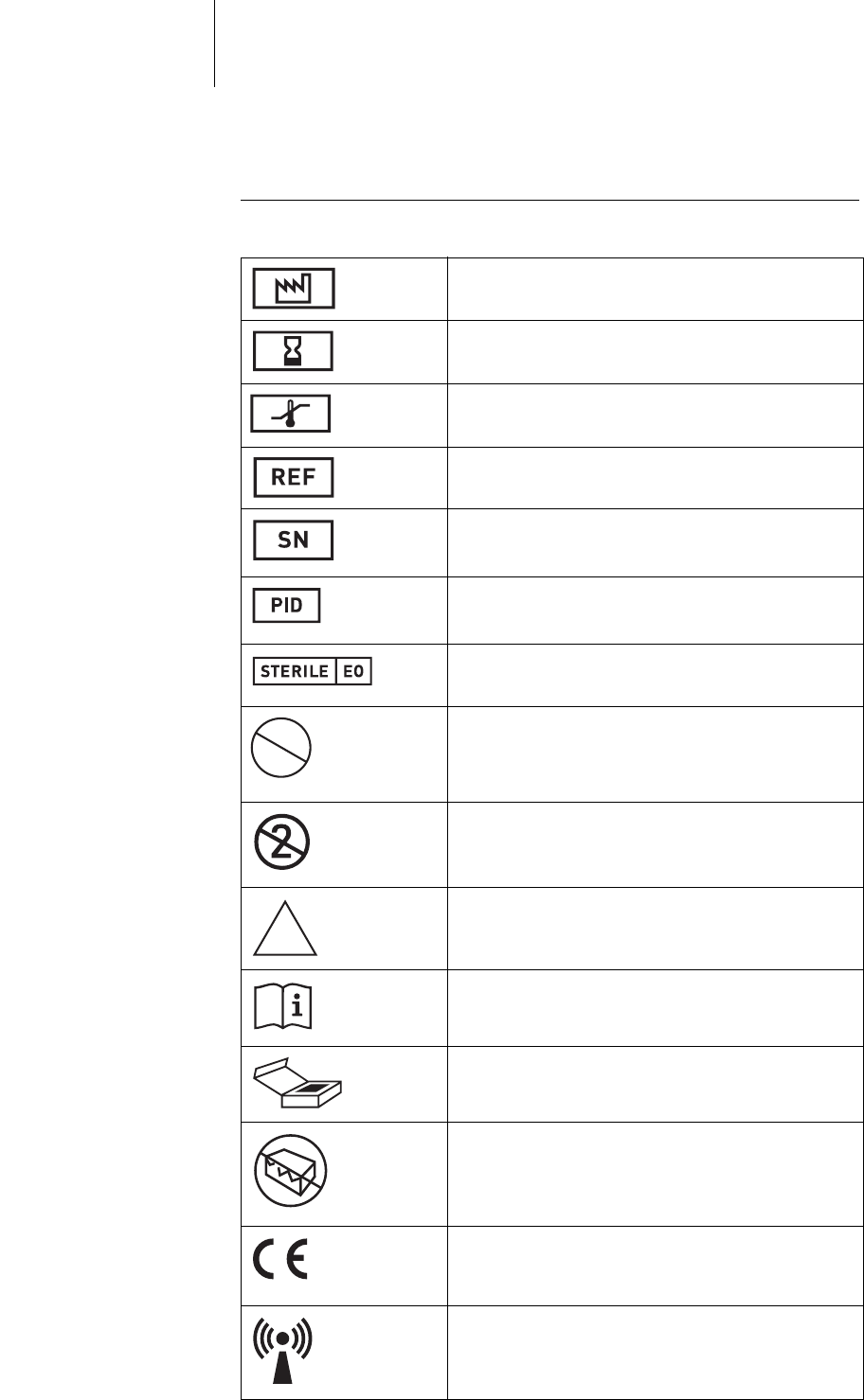
Legend for the Label
The label icons symbolize the following:
Manufacturing date
Expiration date:
Use by
Storage temperature
BIOTRONIK order number
Serial number
Product identification number
Sterilization with ethylene oxide
Resterilization prohibited
Not for reuse
Non-sterile
Usage information
Contents
Do not use if packaging is damaged.
European approval mark
Non-ionizing radiation
STERILIZE
2
NON
STERILE
53 Technical Data
Transfer sheath for leads with PIN-lock PE lead con-
nector (5 mm) to connect to pacemakers with PEC
sockets (6 mm)
Implant with NBG encoding and name of compatible
leads (example)
Silicone-coated implant with NBG encoding and des-
ignation of the compatible leads (example)
Screwdriver
Position of connector ports in the header (example)
Unipolar IS-1 connector
Bipolar IS-1 connector
A Atrium
V Ventricle
UNI/BI Unipolar/bipolar configuration
Vp
Vs
Ventricular pace
Ventricular sense
Ap
As
Atrial pace
Atrial sense
DDDR
A
IS-1

54 Technical Data