BIOTRONIK SE and KG PRIMUS PRIMUS (aka EVIA or ENTOVIS) family of implantable pacemakers User Manual QRIPRIMUS UserMan
BIOTRONIK SE & Co. KG PRIMUS (aka EVIA or ENTOVIS) family of implantable pacemakers QRIPRIMUS UserMan
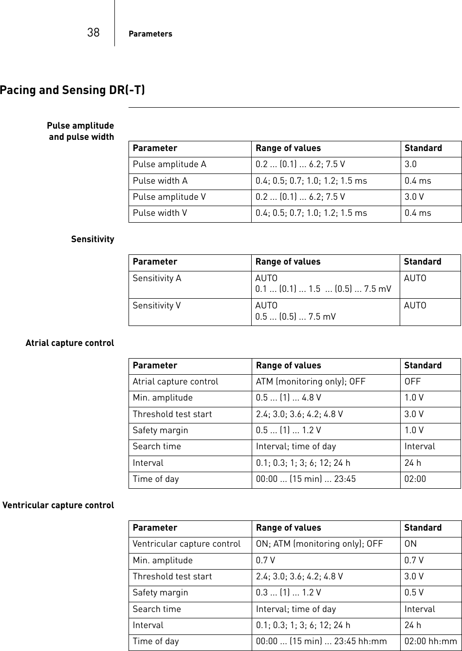
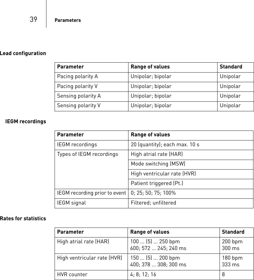
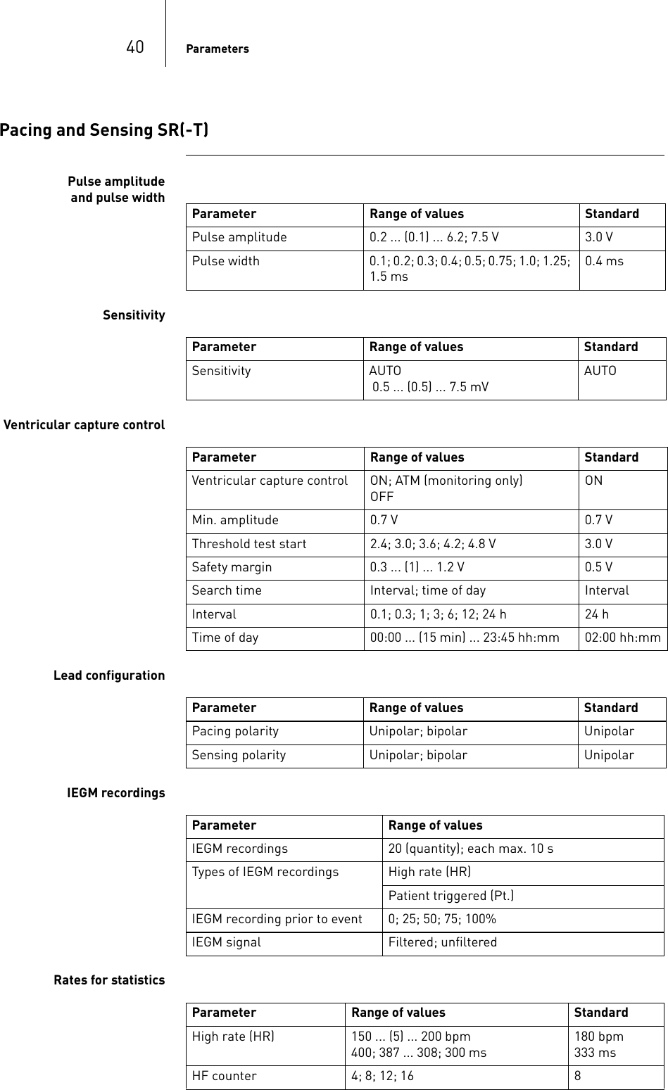
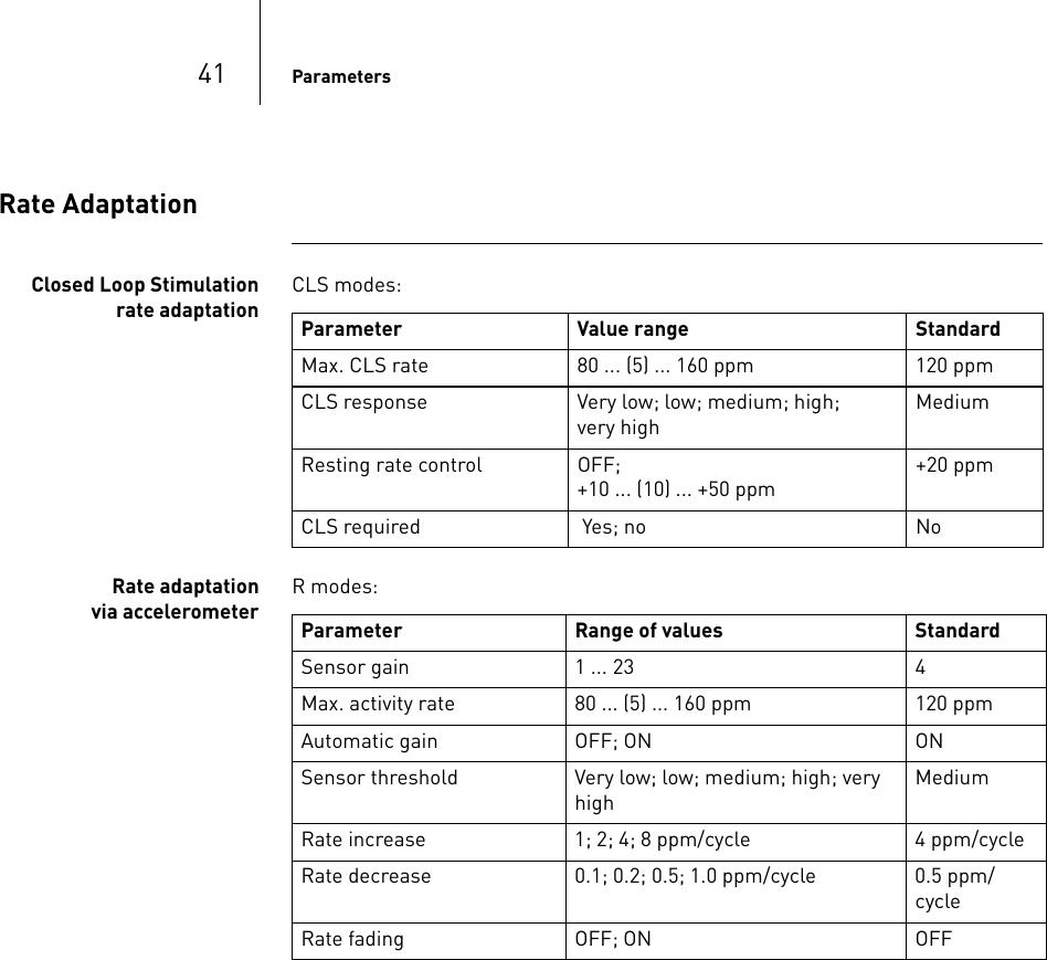
Contents
- 1. QRIPRIMUS UserMan
- 2. R3 QRIPRIMUS UserMan
QRIPRIMUS UserMan
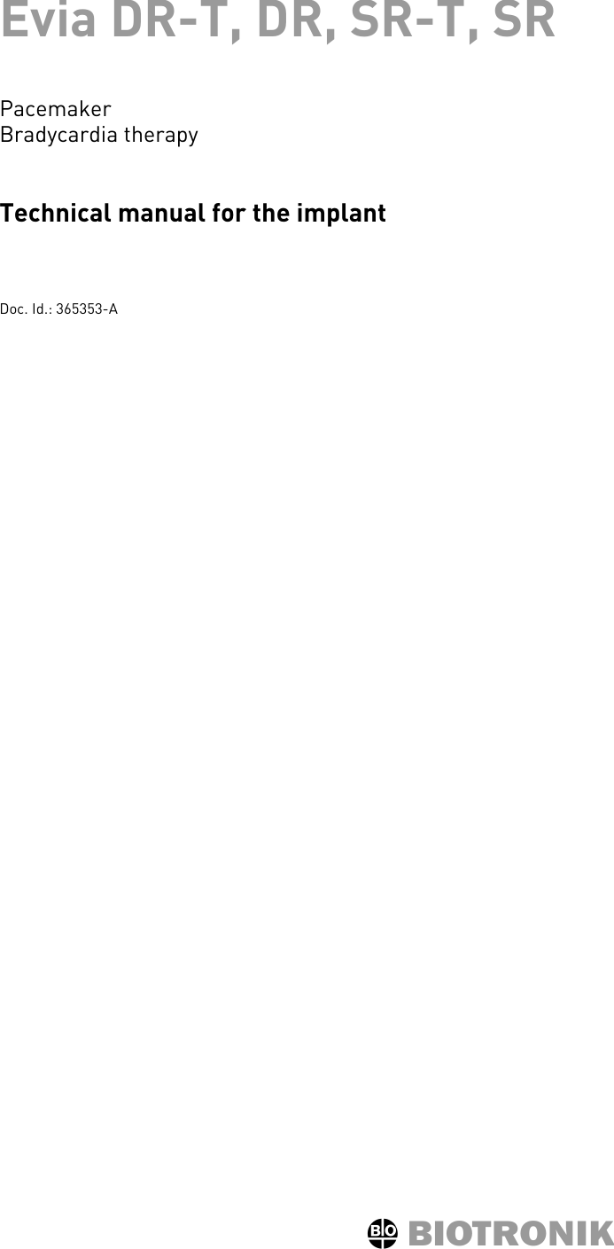
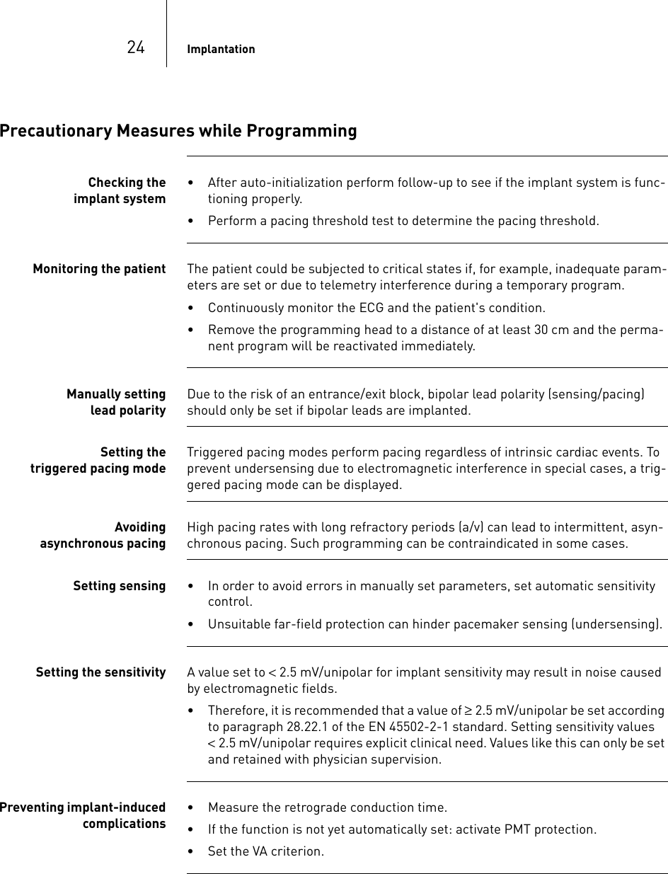
![30 After ImplantationRate decrease The decrease of basic rate and magnet rate is defined as follows:• In the following pacing modes the pacing rate decreases by 11%: DDD(R); DDT(R); DOO(R) VDD(R); VDI(R); VVI(R), VVT(R) AAI(R); AAT(R); AOO(R).• In the pacing modes DDI(R) and DVI(R), only the VA interval is extended by 11%. This reduces the pacing rate by 4.5 to 11%, depending on the configured AV delay.Magnet response at ERI After reaching ERI pacing is performed as follows after applying the magnet or pro-gramming head: Expected service time after ERI• The information is based on a lead impedance of 500 Ohm at 100% pacing and the data of the battery manufacturer.• For a lead impedance of 300 Ohm instead of 500 Ohm, these times decrease by max. 30%.• Parameter with high pulse energy: 110 ppm; 4.6 V; 1.5 ms; 500 Ohm• Parameter with low pulse energy: 30 ppm; 0.2 V; 0.1 ms; 500 Ohm• Dual-chamber implant in DDDR mode; single-chamber implant in AAIR/VVR mode: [in months] Magnet modeCycles 1 to 10: After 10th cycle:Automatically Asynchronous with rate at 80 ppmSynchronous with basic rate reduced by 4.5 to 11%Asynchronous Asynchronous with rate at 80 ppmAsynchronous with rate at 80 ppmSynchronous Synchronous with basic rate reduced by 4.5 to 11%Synchronous with basic rate reduced by 4.5 to 11%ERI to EOS interval Standard program With high pulse energy With low pulse energyMean value 8 8 8Minimum value 6 6 6](https://usermanual.wiki/BIOTRONIK-SE-and-KG/PRIMUS.QRIPRIMUS-UserMan/User-Guide-1211455-Page-31.png)
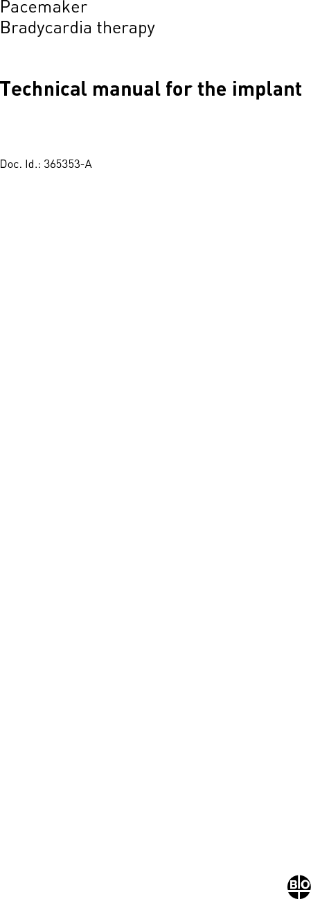
![477 Technical Data Technical Data7365353-ATechnical manual for the implantEvia DR-T, DR, SR- T, SRMechanical CharacteristicsMeasurements for the housingThe measurements refer to the housing without header. Radiopaque marker BIO SFMaterials in contact with body tissue• Housing: titanium• Header: epoxy resin• Sealing plug: silicone• Coating, if applicable: siliconeImplant W x H x D [mm] Volume [cm3] Mass [g]DR-T 53 x 44.5 x 6.5 12 25DR 53 x 43 x 6.5 11 26SR-T 53 x 39 x 6.5 11 24SR 53 x 39 x 6.5 10 25(FCC ID: QRIPRIMUS) This transmitter is authorized by rule under the Medical Device Radiocommunication Service (in part 95 of the FCC Rules) and must not cause harmful interference to stations operating in the 400.150-406.000 MHz band in the Meteorological Aids (i.e., transmitters and receivers used to communicate weather data), the Meteorological Satellite, or the Earth Exploration Satellite Ser-vices and must accept interference that may be caused by such stations, including interference that may cause undesired operation. This transmitter shall be used only in accordance with the FCC Rules governing the Medical Device Radiocom-munication Service. Analog and digital voice communications are prohibited. Although this transmitter has been approved by the Federal Communications Commission, there is no guarantee that it will not receive interference or that any particular transmission from this transmitter will be free from interference.FCC Statement](https://usermanual.wiki/BIOTRONIK-SE-and-KG/PRIMUS.QRIPRIMUS-UserMan/User-Guide-1211455-Page-48.png)
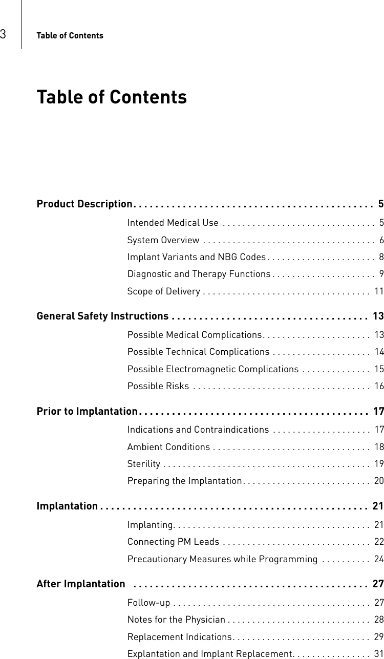
![48 Technical DataElectrical CharacteristicsComponents and input valuesElectrical characteristics determined at 37°C, 500 Ohm Housing shape The implant housing has the following shape: Electrically conductive surfaceThe implant housing has the following surface: Pulse form The pacing pulse has the following form:The pulse amplitude reaches its maximum value at the beginning of the pulse (Ua). With increasing pacing duration (tb), the pulse amplitude is reduced dependent on the pacing impedance.Resistance to interference All variants of BIOTRONIK implants comply with the requirements of prEN 45502-2-2: 2006, Section 27.5.1 at the highest sensitivity.Telemetry Telemetry data for Home Monitoring: Circuit Hybrid electronics with VLSI-CMOS chipInput impedance > 10 kOhmPulse form Biphasic, asymmetricPolarity CathodicImplant type DR(-T), SR(-T)Uncoated Flattened ellipsoidCoated EllipseImplant type DR(-T), SR(-T)Uncoated [cm2]33Coated [cm2]7Nominal carrier frequency Maximum power of transmission403.62 MHz < 25 μW-16 dBm](https://usermanual.wiki/BIOTRONIK-SE-and-KG/PRIMUS.QRIPRIMUS-UserMan/User-Guide-1211455-Page-49.png)
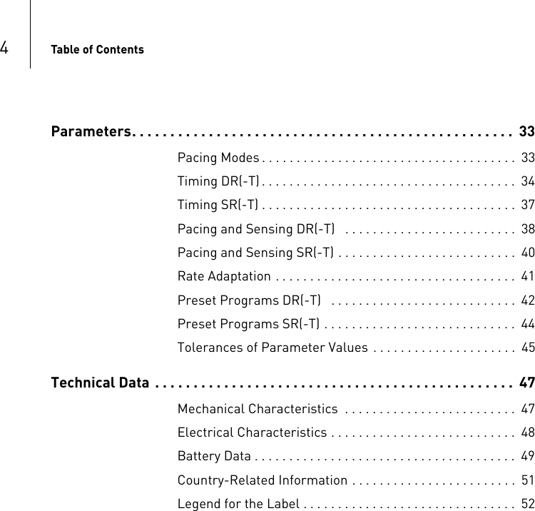
![49 Technical DataBattery DataBattery type characteristics The following data is entered by the manufacturer: Power consumption The implant has the following power consumption: Average service time Average service times are precalculated using the battery manufacturer's technical specifications, a basic rate of 60 ppm and the setting of different pulse amplitudes and lead impedances.Service times DR(-T) For dual-chamber implants, the following times (in years) result: Manufacturer GREATBATCH, INC. Clarence, NY 14031, USA LITRONIK GmbH 01796 Pirna, GermanyBattery type GB 8431 GB 2596 LiS 3150 LiS 3150MSystem LiJ Ag/SVO/CFxQMR® LiJ LiMn02Implant DRSRDR-TSR-TDRSRDR-TSR-TBattery voltage at BOS 2.8 V 3.0 V 2.8 V 3.1 VOpen-circuit volt-age2.8 V 3.0 V 2.8 V 3.1 VNominal capacity 1.3 Ah 1.3 Ah 1.3 Ah 1.2 AhUsable capacity until EOS1.2 Ah 1.1 Ah 1.2 Ah 1.0 AhPower consumption DR(-T) SR(-T)BOS, inhibited 6 μA 6 μABOS, 100% pacing 13 μA 9 μAAmplitude Impedance [Ohms] Pacing10% 50% 100%DR-T DR DR-T DR DR-T DR1.5 V 500 19.3 17.8 17.2 15.8 15.0 13.91000 19.7 18.0 18.3 16.9 17.0 15.72.5 V 500 17.8 16.6 13.6 12.8 9.4 10.01000 18.8 17.4 15.3 14.9 12.5 12.73.0 V 500 17.3 15.8 11.8 10.9 8.5 7.81000 18.5 16.9 14.6 13.4 11.6 10.73.5 V 500 16.5 15.1 10.4 9.7 7.2 6.61000 18.0 16.5 13.4 12.4 10.2 9.45.0 V 500 12.4 12.1 5.4 6.2 3.2 3.81000 15.2 14.6 8.3 9.2 5.3 6.3](https://usermanual.wiki/BIOTRONIK-SE-and-KG/PRIMUS.QRIPRIMUS-UserMan/User-Guide-1211455-Page-50.png)
![50 Technical DataService times SR(-T) For single-chamber implants, the following times (in years) result: Shortening of the service time after long storage periodDepending on the storage period, the service time from the beginning of service BOS to the replacement time ERI decreases as follows: • After 1 year:— DR(-T) by 6 months— SR(-T) by 8 months• After 1.5 years:— DR(-T) by 9 months— SR(-T) by 12 monthsAmplitude Impedance [Ohms] Pacing10% 50% 100%SR-T SR SR-T SR SR-T SR1.5 V 500 23.3 21.3 21.7 19.8 19.9 18.31000 23.6 21.5 22.7 20.7 21.6 19.82.5 V 500 22.1 20.3 17.8 17.3 14.3 14.61000 22.8 21.0 20.2 19.2 17.5 17.23.0 V 500 21.7 19.8 16.8 15.5 13.2 12.21000 22.7 20.7 19.5 17.8 16.6 15.33.5 V 500 20.9 19.1 15.3 14.2 11.5 10.71000 22.3 20.3 18.4 16.9 15.1 13.95.0 V 500 17.2 16.3 9.1 10.1 5.7 6.81000 19.8 18.7 12.8 13.7 8.9 10.2](https://usermanual.wiki/BIOTRONIK-SE-and-KG/PRIMUS.QRIPRIMUS-UserMan/User-Guide-1211455-Page-51.png)