BIOTRONIK SE and KG PRIMUS PRIMUS (aka EVIA or ENTOVIS) family of implantable pacemakers User Manual R3 QRIPRIMUS UserMan
BIOTRONIK SE & Co. KG PRIMUS (aka EVIA or ENTOVIS) family of implantable pacemakers R3 QRIPRIMUS UserMan
Contents
- 1. QRIPRIMUS UserMan
- 2. R3 QRIPRIMUS UserMan
R3 QRIPRIMUS UserMan
Evia
Family of Implantable Pulse Generators
Technical Manual
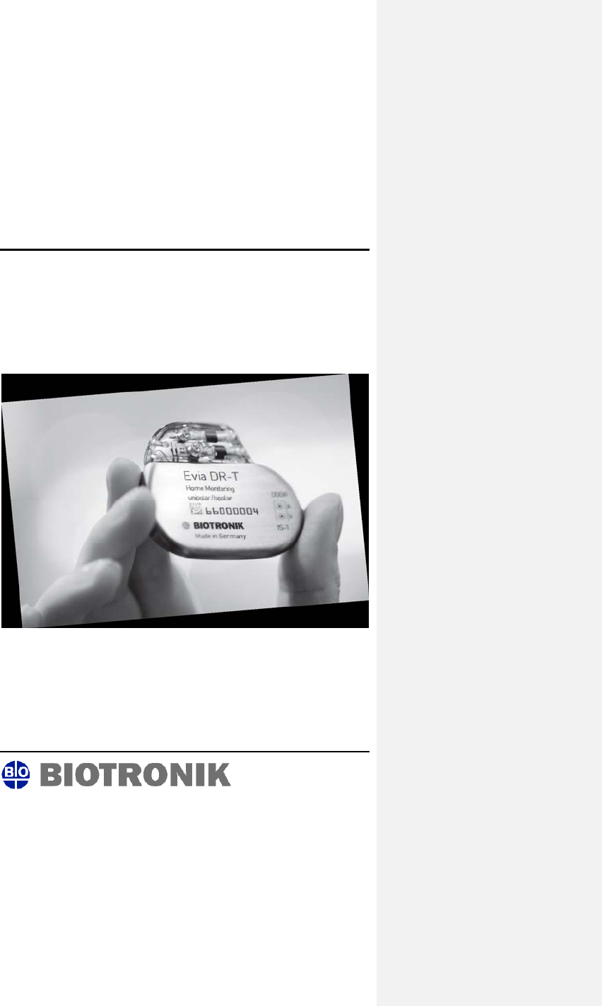
Evia
Implantable Pulse Generators
Evia DR
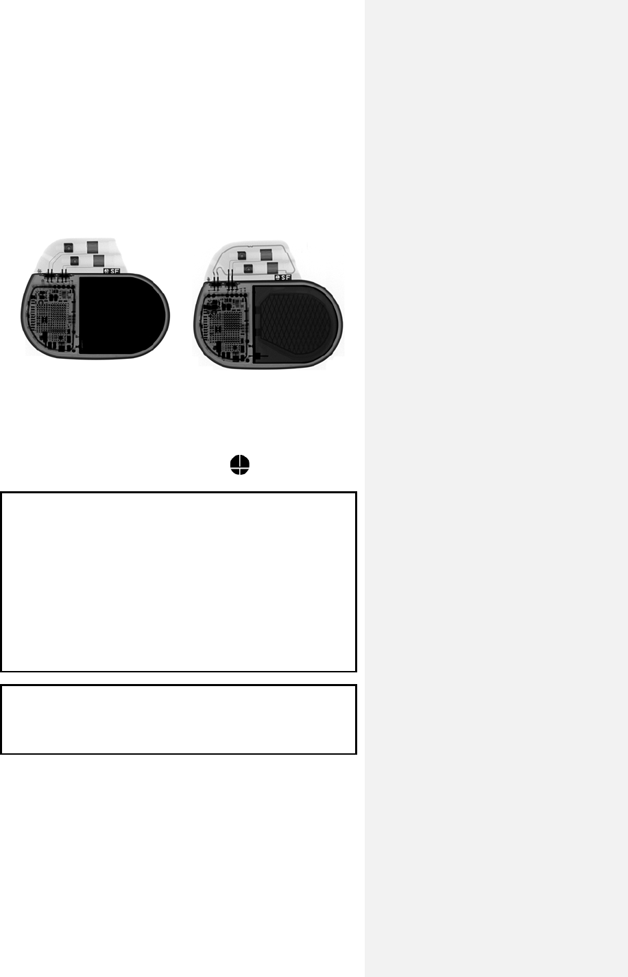
X-Ray identification Evia DR-T
X-Ray identification
Radiopaque Identification
A radiopaque identification code is visible on standard x-ray, and
identifies the pulse generator:
Evia DR, DR-T, SR, and SR-T SF
CAUTION
Because of the numerous available 3.2-mm configurations
(e.g., the IS-1 and VS-1 standards), lead/pulse generator
compatibility should be confirmed with the pulse generator
and/or lead manufacturer prior to the implantation of a pacing
system.
IS-1, wherever stated in this manual, refers to the
international standard, whereby leads and generators from
different manufacturers are assured a basic fit.
[Reference ISO 5841-3:1992(E)].
CAUTION
Federal (U.S.A.) law restricts this device to sale by or on the
order of, a physician (or properly licensed practitioner).
©2009 BIOTRONIK, Inc., all rights reserved.

Evia Technical Manual i
Contents
1. Device Description .......................................................... 1
2. Indications ........................................................................ 4
3. Contraindications ............................................................ 6
4. Warnings and Precautions ............................................. 8
4.1 Medical Therapy .......................................................... 8
4.2 Storage and Sterilization ........................................... 10
4.3 Lead Connection and Evaluation .............................. 10
4.4 Programming and Operation ..................................... 12
4.5 Home Monitoring ....................................................... 14
4.6 Electromagnetic Interference (EMI) .......................... 15
4.6.1 Home and Occupational Environments ............... 16
4.6.2 Cellular Phones .................................................... 17
4.6.3 Hospital and Medical Environments .................... 18
4.7 Pulse Generator Explant and Disposal ..................... 19
5. Adverse Events .............................................................. 21
5.1 Observed Adverse Events ......................................... 21
5.1.1 Dromos DR Clinical Study ................................... 21
5.1.2 PACC Clinical Study ............................................ 23
5.1.3 Inos2+ CLS Clinical Study ................................... 24
5.2 Potential Adverse Events .......................................... 26
6. Clinical Study ................................................................. 27
6.1 Dromos DR ................................................................ 27
6.2 Ventricular Capture Control ....................................... 28
6.2.1 Primary Objectives ............................................... 29
6.2.2 Methods ............................................................... 29
6.2.3 Results ................................................................. 29
6.2.4 Clinical Study Conclusions ................................... 34
6.3 Closed Loop Stimulation (CLS) ................................. 35
6.3.1 Protos DR/CLS Response to Mental Stress ........ 35
6.3.2 Protos DR CLS with AxVx .................................... 38
6.3.3 Inos2+ CLS ............................................................ 41
6.4 TRUST Clinical Study ................................................ 44
6.4.1 Study Overview .................................................... 44
6.4.2 Methods ............................................................... 45
6.4.3 Summary of Clinical Results ................................ 47

ii Evia Technical Manual
6.4.4 Conclusions .......................................................... 51
7. Programmable Parameters ........................................... 53
7.1 Pacing Modes ............................................................ 53
7.1.1 Motion Based Rate-Adaptive Modes ................... 53
7.1.2 CLS Modes .......................................................... 53
7.1.3 Non-Rate-Adaptive Modes ................................... 54
7.1.4 Mode Switching .................................................... 55
7.1.5 Pacing Modes with Triggered Response ............. 56
7.2 Rate Related Functions ............................................. 57
7.2.1 Basic Rate ............................................................ 57
7.2.2 Rate Hysteresis .................................................... 58
7.2.3 Scan Hysteresis ................................................... 59
7.2.4 Repetitive Hysteresis ........................................... 60
7.2.5 Night Mode ........................................................... 61
7.2.6 Rate Fading .......................................................... 62
7.3 Pulse Specific Features ............................................. 63
7.3.1 Pulse Amplitude ................................................... 63
7.3.2 Pulse Width .......................................................... 64
7.4 Automatic Sensitivity Control (ASC) .......................... 64
7.5 Timing Features ........................................................ 65
7.5.1 Refractory Periods ............................................... 65
7.5.2 PVARP ................................................................. 65
7.5.3 AV Delay .............................................................. 67
7.5.4 Ventricular Blanking Period .................................. 71
7.5.5 Atrial Blanking Period ........................................... 72
7.5.6 Far-Field Protection ............................................. 72
7.5.7 Safety AV Delay ................................................... 72
7.5.8 Upper Rate and UTR Response .......................... 73
7.6 Lead Polarity ............................................................. 73
7.7 Parameters for Rate-Adaptive Pacing ...................... 74
7.7.1 Sensor Gain ......................................................... 75
7.7.2 Automatic Sensor Gain ........................................ 76
7.7.3 Sensor Threshold ................................................. 77
7.7.4 Rate Increase ....................................................... 78
7.7.5 Maximum Sensor Rate ........................................ 79
7.7.6 Maximum Closed Loop Rate ................................ 79
7.7.7 Rate Decrease ..................................................... 80
7.8 Management of Specific Scenarios ........................... 81
7.8.1 2:1 Lock-In Management ..................................... 81
7.9 Atrial Upper Rate ....................................................... 82
7.10 Atrial Overdrive Pacing (Overdrive Mode) ................ 83

Evia Technical Manual iii
7.11 Management of Specific Scenarios ........................... 84
7.11.1 PMT Management ............................................... 84
7.11.2 PMT Protection .................................................... 85
7.12 Adjustment of the PMT Protection Window .............. 86
7.13 Ventricular Capture Control (VCC) ............................ 87
7.13.1 Feature Description .............................................. 87
7.13.2 Ventricular Capture Control Programming........... 96
7.14 Program Consult® ...................................................... 97
7.15 Home Monitoring (Evia DR-T) ................................. 101
7.15.1 Transmission of Information ............................... 102
7.15.2 Patient Device .................................................... 102
7.15.3 Transmitting Data ............................................... 103
7.15.4 Types of Report Transmissions ......................... 105
7.15.5 Description of Transmitted Data ........................ 106
8. Statistics ....................................................................... 109
8.1 Statistics Overview .................................................. 109
8.1.1 Timing ................................................................ 109
8.1.2 Atrial Arrhythmia ................................................. 109
8.1.3 Sensor ................................................................ 109
8.1.4 Sensing .............................................................. 110
8.1.5 Ventricular Arrhythmia ....................................... 110
8.1.6 Pacing ................................................................ 110
8.1.7 General Statistical Information ........................... 110
8.2 Timing Statistics ...................................................... 111
8.2.1 Event Counter .................................................... 111
8.2.2 Event Counter .................................................... 111
8.2.3 Event Episodes .................................................. 112
8.2.4 Rate Trend 24 Hours ......................................... 112
8.2.5 Rate Trend 240 Days ......................................... 112
8.2.6 Atrial and Ventricular Rate Histogram ............... 113
8.3 Arrhythmia Statistics ................................................ 113
8.3.1 Atrial Burden ...................................................... 113
8.3.2 Time of occurrence ............................................ 113
8.3.3 Mode Switching .................................................. 113
8.3.4 Ventricular Arrhythmia ....................................... 114
8.4 Sensor Statistics ...................................................... 114
8.4.1 Sensor Histogram .............................................. 114
8.4.2 Activity Report .................................................... 115
8.5 Pacing Statistics ...................................................... 115
8.5.1 Ventricular Pacing Amplitude Histogram ........... 116
8.5.2 V Pacing Threshold Trend ................................. 116

iv Evia Technical Manual
8.5.3 Capture Control Status ...................................... 117
8.6 Sensing Statistics .................................................... 117
8.7 IEGM Snapshots ..................................................... 118
9. Other Functions/Features ........................................... 121
9.1 Safe Program Settings ............................................ 121
9.2 Magnet Effect .......................................................... 121
9.3 Temporary Programming ......................................... 122
9.4 Patient Data Memory ............................................... 123
9.5 Position Indicator ..................................................... 124
9.6 Pacing When Exposed to Interference ................... 125
10. Product Storage and Handling ................................... 126
10.1 Sterilization and Storage ......................................... 126
10.2 Opening the Sterile Container ................................. 127
10.3 Pulse Generator Orientation ................................... 128
11. Lead Connection .......................................................... 130
11.1 Auto Initialization ..................................................... 133
12. Follow-up Procedures ................................................. 136
12.1 General Considerations .......................................... 136
12.2 Real-time IEGM Transmission ................................ 137
12.3 Threshold Test ......................................................... 137
12.4 P/R Measurement ................................................... 138
12.5 Testing for Retrograde Conduction ......................... 139
12.6 Non-Invasive Programmed Stimulation (NIPS) ....... 139
12.6.1 Description ......................................................... 139
12.6.2 Burst Stimulation ................................................ 140
12.6.3 Programmed Stimulation ................................... 140
12.6.4 Back up Pacing .................................................. 140
12.6.5 NIPS Safety Features ........................................ 141
12.7 Optimizing Rate Adaptation ..................................... 142
12.7.1 Rate/Sensor Trend ............................................. 142
12.7.2 Adjusting the Sensor Gain ................................. 143
12.7.3 Adjusting the Sensor Threshold ......................... 143
13. Elective Replacement Indication (ERI) ...................... 145
14. Explantation ................................................................. 149
14.1 Common Reasons to Explant a Pulse Generator ... 149
15. Technical Data .............................................................. 153
15.1 Modes . .................... ................... .................... .......... 1 53

Evia Technical Manual v
15.2 Pulse- and Control Parameters ............................... 154
15.2.1 Rate Adaptation ................................................. 157
15.2.2 Ventricular Capture Control (VCC) .................... 158
15.2.3 Home Monitoring Parameters ............................ 158
15.2.4 Additional Functions ........................................... 160
15.2.5 NIPS Specifications ........................................... 161
15.3 Programmer ............................................................ 161
15.4 Materials in Contact with Human Tissue ................. 161
15.5 Electrical Data/Battery ............................................. 161
15.6 Mechanical Data ...................................................... 163
16. Order Information ........................................................ 164
Appendix A ........................................................................ 166
Appendix B ........................................................................ 172
CAUTION
Federal (U.S.A.) law restricts this device to sale by, or on the
order of, a physician (or properly licensed practitioner).

vi Evia Technical Manual

Evia Technical Manual 1
1. Device Description
Evia is a multi-programmable, dual chamber pulse generator
with rate-adaptive pacing. The Evia family of pulse generators is
BIOTRONIK’s state of the art pacing system with two methods of
rate-adaptation. Rate-adaptation is achieved through
programming of either the unique principle of closed-loop
stimulation (CLS) or by motion-based pacing via a capacitive
accelerometer.
The basic function of CLS involves the translation of myocardial
contractility into patient-specific pacing rates. Specifically, the
pulse generator monitors and processes the intracardiac
impedance signals associated with myocardial contraction
dynamics. Changes in the waveform of this impedance signal
are associated with changes in the contraction dynamics of the
patient's heart due to the heart’s inotropic response to exercise
and acute mental stress. By monitoring these changes, the
pulse generator can provide a pacing rate that is appropriate and
specific to the patient’s individual physiologic demands due to
exercise and acute mental stress.
For standard motion-based rate-adaptation, the Evia is equipped
with an accelerometer located within the pulse generator. This
sensor produces an electric signal during physical activity of the
patient. If a rate-adaptive (R) mode is programmed, then the
accelerometer sensor signal controls the stimulation rate.
Evia also employs Home Monitoring™ technology, which is an
automatic, wireless, remote monitoring system for management
of patients with pulse generators. With Home Monitoring,
physicians can review data about the patient’s cardiac status
and pulse generator’s functionality between regular follow-up
visits, allowing the physician to optimize the therapy process.
BIOTRONIK conducted the TRUST study to evaluate the safety
and effectiveness of Home Monitoring. Refer to Section 6.4 for
details regarding the study design and results. With the TRUST
study, BIOTRONIK was able to show the following with regards
to Home Monitoring:

2 Evia Technical Manual
• BIOTRONIK Home Monitoring information may be used as a
replacement for device interrogation during in-office follow-
up visits.
• A strategy of care using BIOTRONIK Home Monitoring with
office visits when needed has been shown to extend the
time between routine, scheduled in-office follow-ups of
BIOTRONIK implantable devices in many patients. Home
Monitoring data is helpful in determining the need for
additional in-office follow-up.
• BIOTRONIK Home Monitoring-patients—who are followed
remotely with office visits when needed—have been shown
to have similar numbers of strokes, invasive procedures and
deaths as patients followed with conventional in-office
follow-ups.
• BIOTRONIK Home Monitoring provides early detection of
arrhythmias.
• BIOTRONIK Home Monitoring provides early detection of
silent, asymptomatic arrhythmias.
• Automatic early detection of arrhythmias and device system
anomalies by BIOTRONIK Home Monitoring allows for
earlier intervention than conventional in-office follow-ups.
• BIOTRONIK Home Monitoring allows for improved access to
patient device data compared to conventional in-office
follow-ups since device interrogation is automatically
scheduled at regular intervals.
Evia provides single and dual chamber pacing in a variety of
rate-adaptive and non-rate adaptive pacing modes. Pacing
capability is supported by a sophisticated diagnostic set.
The device is designed and recommended for use with atrial and
ventricular unipolar or bipolar leads having IS-1 compatible
connectors. (Note that IS-1 refers to the International Standard
whereby leads and generators from different manufacturers are
assured a basic fit [Reference ISO 5841-3:1992]).

Evia Technical Manual 3
Evia is designed to meet all indications for bradycardia therapy
as exhibited in a wide variety of patients. The family is
comprised of four pulse generators that are designed to handle a
multitude of situations. The four pulse generators include:
Evia DR Dual chamber, rate-adaptive,
unipolar/bipolar
Evia DR-T Dual chamber, rate-adaptive,
unipolar/bipolar, with Home Monitoring
Evia SR Single chamber, rate-adaptive,
unipolar/bipolar
Evia SR-T Single chamber, rate-adaptive,
unipolar/bipolar, with Home Monitoring
Throughout this manual, specific feature and function
descriptions may only be applicable to certain pulse generators
of the Evia family. If specified as dual chamber configurations,
the descriptions are specifically referring to Evia DR and
Evia DR-T. If specified as single chamber configurations, the
descriptions are specifically referring to Evia SR and Evia SR-T.

4 Evia Technical Manual
2. Indications
Rate-adaptive pacing with Evia pulse generators is indicated for
patients exhibiting chronotropic incompetence and who would
benefit from increased pacing rates concurrent with physical
activity.
Generally accepted indications for long-term cardiac pacing
include, but are not limited to: sick sinus syndrome (i.e.
bradycardia-tachycardia syndrome, sinus arrest, sinus
bradycardia), sino-atrial (SA) block, second- and third- degree
AV block, and carotid sinus syndrome.
Patients who demonstrate hemodynamic benefit through
maintenance of AV synchrony should be considered for one of
the dual chamber or atrial pacing modes. Dual chamber modes
are specifically indicated for treatment of conduction disorders
that require both restoration of rate and AV synchrony such as
AV nodal disease, diminished cardiac output or congestive heart
failure associated with conduction disturbances, and
tachyarrhythmias that are suppressed by chronic pacing.

Evia Technical Manual 5

6 Evia Technical Manual
3. Contraindications
Use of Evia pulse generators is contraindicated for the following
patients:
• Unipolar pacing is contraindicated for patients with an
implanted cardioverter-defibrillator (ICD) because it may
cause unwanted delivery or inhibition of ICD therapy.
• Single chamber atrial pacing is contraindicated for
patients with impaired AV nodal conduction.
• Dual chamber and single chamber atrial pacing is
contraindicated for patients with chronic refractory atrial
tachyarrhythmias.
For a complete discussion of mode-specific contraindications,
please refer to Appendix A of this manual.

Evia Technical Manual 7

8 Evia Technical Manual
4. Warnings and Precautions
Certain therapeutic and diagnostic procedures may cause
undetected damage to a pulse generator, resulting in
malfunction or failure at a later time. Please note the following
warnings and precautions:
Magnetic Resonance Imaging (MRI) – Avoid use of magnetic
resonance imaging as it has been shown to cause movement of
the pulse generator within the subcutaneous pocket and may
cause pain and injury to the patient and damage to the pulse
generator. If the procedure must be used, constant monitoring is
recommended, including monitoring the peripheral pulse.
Rate-Adaptive Pacing – Use rate-adaptive pacing with care in
patients unable to tolerate increased pacing rates.
4.1 Medical Therapy
Before applying one of the following procedures, a detailed
analysis of the advantages and risks should be made. Cardiac
activity during one of these procedures should be confirmed by
continuous monitoring of peripheral pulse or blood pressure.
Following the procedures, pulse generator function and
stimulation threshold must be checked.
Therapeutic Diathermy Equipment – Use of therapeutic
diathermy equipment is to be avoided for pacemaker patients
due to possible heating effects of the pulse generator and at the
implant site. If diathermy therapy must be used, it should not be
applied in the immediate vicinity of the pulse generator/lead.
The patient's peripheral pulse should be monitored continuously
during the treatment.

Evia Technical Manual 9
Transcutaneous Electrical Nerve Stimulation (TENS) –
Transcutaneous electrical nerve stimulation may interfere with
pulse generator function. If necessary, the following measures
may reduce the possibility of interference:
• Place the TENS electrodes as close to each other as
possible.
• Place the TENS electrodes as far from the pulse
generator/lead system as possible.
• Monitor cardiac activity during TENS use.
Defibrillation – The following precautions are recommended to
minimize the inherent risk of pulse generator operation being
adversely affected by defibrillation:
• The paddles should be placed anterior-posterior or along
a line perpendicular to the axis formed by the pulse
generator and the implanted lead.
• The energy setting should not be higher than required to
achieve defibrillation.
• The distance between the paddles and the
pacer/electrode(s) should not be less than 10 cm
(4 inches).
Radiation – Pulse generator electronics may be damaged by
exposure to radiation during radiotherapy. To minimize this risk
when using such therapy, the pulse generator should be
protected with local radiation shielding.
Lithotripsy – Lithotripsy treatment should be avoided for
pacemaker patients since electrical and/or mechanical
interference with the pulse generator is possible. If this
procedure must be used, the greatest possible distance from the
point of electrical and mechanical strain should be chosen in
order to minimize a potential interference with the pulse
generator.
Electrocautery – Electrocautery should never be performed
within 15 cm (6 inches) of an implanted pulse generator or lead
because of the danger of introducing fibrillatory currents into the
heart and/or damaging the pulse generator. Pacing should be
asynchronous and above the patient’s intrinsic rate to prevent
inhibition by interference signals generated by the cautery.
When possible, a bipolar electrocautery system should be used.

10 Evia Technical Manual
For transurethral resection of the prostate, it is recommended
that the cautery ground plate be placed under the buttocks or
around the thigh, but not in the thoracic area where the current
pathway could pass through or near the pacing system.
4.2 Storage and Sterilization
Storage (temperature) – Recommended storage temperature
range is 5° to 55°C (41°-131°F). Exposure to temperatures
outside this range may result in pulse generator malfunction (see
Section 10.1).
Handling – Do not drop. If an unpackaged pulse generator is
dropped onto a hard surface, return it to BIOTRONIK (see
Section 10.1).
FOR SINGLE USE ONLY - Do not resterilize the pulse
generator or accessories packaged with the pulse generator,
they are intended for one-time use.
Device Packaging – Do not use the device if the packaging is
wet, punctured, opened or damaged because the integrity of the
sterile packaging may be compromised. Return the device to
BIOTRONIK.
Storage (magnets) – Store the device in a clean area, away
from magnets, kits containing magnets, and sources of
electromagnetic interference (EMI) to avoid damage to the
device.
Temperature Stabilization – Allow the device to reach room
temperature before programming or implanting the device.
Temperature extremes may affect the initial device function.
Use Before Date – Do not implant the device after the USE
BEFORE DATE because the device sterility and longevity may
be compromised.
4.3 Lead Connection and Evaluation
The pulse generator requires atrial and ventricular leads with IS-
1 compatible connectors. There are no requirements specific to
the atrial lead. It is required to use a low polarization ventricular
lead for activation of Ventricular Capture Control.

Evia Technical Manual 11
Ventricular Capture Control - The Ventricular Capture Control
feature should be programmed OFF before lead connection. The
feature is designed to measure thresholds and will automatically
reprogram the ventricular pulse amplitude. In the absence of a
connected lead, the feature will not be able to perform these
measurements and set the output to an appropriate value.
Lead Check – The Evia pulse generators have an automatic
lead check feature which may switch from bipolar to unipolar
pacing and sensing without warning. This situation may be
inappropriate for patients with an Implantable Cardioverter
Defibrillator (ICD).
Lead/pulse Generator Compatibility – Because of the
numerous available 3.2-mm configurations (e.g., the IS-1 and
VS-1 standards), lead/pulse generator compatibility should be
confirmed with the pulse generator and/or lead manufacturer
prior to the implantation of a pacing system.
IS-1, wherever stated in this manual, refers to the international
standard, whereby leads and generators from different
manufacturers are assured a basic fit. [Reference ISO 5841-
3:1992(E)].
Lead Configuration – Lead configuration determines proper
programming of the pulse generator. Pacing will not occur with a
unipolar lead if the lead configuration is programmed to bipolar.
Setscrew Adjustment – Back-off the setscrew(s) prior to
insertion of lead connector(s) as failure to do so may result in
damage to the lead(s), and/or difficulty connecting lead(s).
Cross Threading Setscrew(s) – To prevent cross threading
the setscrew(s), do not back the setscrew(s) completely out of
the threaded hole. Leave the torque wrench in the slot of the
setscrew(s) while the lead is inserted.
Tightening Setscrew(s) – Do not overtighten the setscrew(s).
Use only the BIOTRONIK supplied torque wrench.
Sealing System – Be sure to properly insert the torque
wrench into the perforation at an angle perpendicular to the
connector receptacle. Failure to do so may result in damage to
the plug and its self-sealing properties.

12 Evia Technical Manual
4.4 Programming and Operation
Negative AV Delay Hysteresis – This feature insures
ventricular pacing, a technique which has been used in patients
with hypertrophic obstructive cardiomyopathy (HOCM) with
normal AV conduction in order to replace intrinsic ventricular
activation. No clinical study was conducted to evaluate this
feature, and there is conflicting evidence regarding the potential
benefit of ventricular pacing therapy for HOCM patients. In
addition, there is evidence with other patient groups to suggest
that inhibiting the intrinsic ventricular activation sequence by
right ventricular pacing may impair hemodynamic function and/or
survival.
Programming VCC – If the SA/CV sequence is not successful,
program the VCC to OFF and program the pacing pulse
amplitude manually.
NIPS - Life threatening ventricular arrhythmias can be induced
by stimulation in the atrium. Ensure that an external cardiac
defibrillator is easily accessible. Only physicians trained and
experienced in tachycardia induction and reversion protocols
should use non-invasive programmed stimulation (NIPS).
Unipolar/Bipolar – All Evia models can be used with either
unipolar or bipolar IS-1 leads.
If the pacing or sensing function is to be programmed to bipolar,
it must be verified that bipolar leads have been implanted in
that chamber. If either of the leads is unipolar, unipolar
sensing and pacing functions must be programmed in that
chamber. Failure to program the appropriate lead configuration
could result in entrance and/or exit block.
Programmers – Use only appropriate BIOTRONIK
programmers equipped with appropriate software to program
Evia pulse generators. Do not use programmers from other
manufacturers.
Pulse Amplitude – Programming of pulse amplitudes, higher
than 4.8 V, in combination with long pulse widths and/or high
pacing rates can lead to premature activation of the replacement
indicator.

Evia Technical Manual 13
Pacing thresholds – When decreasing programmed output
(pulse amplitude and/or pulse width), the pacing threshold must
first be accurately assessed to provide a 2:1 safety margin.
When using the Ventricular Capture Control feature, the device
will automatically set the output to the measured threshold plus
the programmed Safety Margin. A new threshold search will
occur at scheduled intervals or upon loss of capture.
EMI – Computerized systems are subject to EMI or “noise”. In
the presence of such interference, telemetry communication may
be interrupted and prevent programming.
Programming Modifications – Extreme programming changes
should only be made after careful clinical assessment. Clinical
judgment should be used when programming permanent pacing
rates below 40 ppm or above 100 ppm.
Short Pacing Intervals – Use of short pacing intervals (high
pacing rates) with long atrial and/or ventricular refractory periods
may result in intermittent asynchronous pacing and, therefore,
may be contraindicated in some patients.
OFF Mode – Use of the OFF mode should be avoided in
pacemaker dependent patients. The OFF mode can be
transmitted as a temporary program only to permit evaluation of
the patient’s spontaneous rhythm.
Myopotential Sensing – The filter characteristics of
BIOTRONIK pulse generators have been optimized to sense
electrical potentials generated by cardiac activity and to reduce
the possibility of sensing skeletal myopotentials. However, the
risk of pulse generator operation being affected by myopotentials
cannot be eliminated, particularly in unipolar systems.
Myopotentials may resemble cardiac activity, resulting in pulse
generator pulse inhibition, triggering and/or emission of
asynchronous pacing pulses, depending on the pacing mode
and the interference pattern. Certain follow-up procedures, such
as monitoring pulse generator performance while the patient is
doing exercises involving the use of pectoral muscles, as well as
Holter monitoring, have been recommended to check for
interference caused by myopotentials. If sensing of
myopotentials is encountered, corrective actions may include
selection of a different pacing mode or sensitivity.

14 Evia Technical Manual
Muscle or Nerve Stimulation – Inappropriate muscle or nerve
stimulation may occur with unipolar pacing when using a non-
coated pulse generator.
CLS Rate-Adaptation – Under certain circumstances (e.g., EMI,
lead dislodgment), the Evia device may not be able to obtain a
useable impedance measurement as required for CLS
rate-adaptive pacing. At this point, CLS rate-adaptation will be
inactive until the situation is corrected. Rate-adaptation may be
programmed to switch to motion based adaptation.
Programmed to Triggered Modes – When programmed to
triggered modes, pacing rates up to the programmed upper limit
may occur in the presence of either muscle or external
interference.
Triggered Modes – While the triggered modes (DDT, VVT, and
AAT) can be programmed permanently, the use of these modes
is intended as a temporary setting in situations where
maintaining the programming head in place would be impossible
or impractical (i.e., during exercise testing or extended Holter
monitoring) or as a short term solution to pulse generator
inhibition by extracardiac interference. To avoid the potential for
early battery depletion, it is important that the triggered modes
are not used for long term therapy, and that the pulse generator
is returned to a non-triggered permanent program.
4.5 Home Monitoring
BIOTRONIK’s Home Monitoring system is designed to notify
clinicians in less than 24 hours of changes to the patient’s
condition or status of the implanted device. Updated data may
not be available if:
• The patient’s CardioMessenger is off or damaged and is
not able to connect to the Home Monitoring system through
an active telephone link.
• The CardioMessenger cannot establish a connection to the
implanted device.
• The telephone and/or Internet connection do not operate
properly

Evia Technical Manual 15
• The Home Monitoring Service Center is off-line (upgrades
are typically completed in less than 24 hours)”
Patient’s Ability - Use of the Home Monitoring system requires
the patient and/or caregiver to follow the system instructions and
cooperate fully when transmitting data.
If the patient cannot understand or follow the instructions
because of physical or mental challenges, another adult who can
follow the instructions will be necessary for proper transmission.
Electromagnetic Interference (EMI) – Precautions for EMI
interference with the Evia DR-T pulse generator are provided in
Section 4.6. Sources of EMI including cellular telephones,
electronic article surveillance systems, and others are discussed
therein.
Use in Cellular Phone Restricted Areas - The mobile patient
device (transmitter/receiver) should not be utilized in areas
where cellular phones are restricted or prohibited (i.e.,
commercial aircraft).
4.6 Electromagnetic Interference (EMI)
The operation of any implanted pulse generator may be affected
by certain environmental sources generating signals that
resemble cardiac activity. This may result in pulse generator
pulse inhibition and/or triggering or in asynchronous pacing
depending on the pacing mode and the interference pattern. In
some cases (i.e., diagnostic or therapeutic medical procedures),
the interference sources may couple sufficient energy into a
pacing system to damage the pulse generator and/or cardiac
tissue adjacent to the electrodes.
BIOTRONIK pulse generators have been designed to
significantly reduce susceptibility to electromagnetic interference
(EMI). However, due to the variety and complexity of sources
creating interference, there is no absolute protection against
EMI. Generally, it is assumed that EMI produces only minor
effects, if any, in pacemaker patients. If the patient presumably
will be exposed to one of the following environmental conditions,
then the patient should be given the appropriate warnings.

16 Evia Technical Manual
4.6.1 Home and Occupational Environments
The following equipment (and similar devices) may affect normal
pulse generator operation: electric arc welders, electric melting
furnaces, radio/television and radar transmitters,
power-generating facilities, high-voltage transmission lines,
electrical ignition systems (also of gasoline-powered devices) if
protective hoods, shrouds, etc., are removed, electrical tools,
anti-theft devices of shopping centers and electrical appliances,
if not in proper condition or not correctly grounded and encased.
Patients should exercise reasonable caution in avoidance of
devices which generate a strong electric or magnetic field. If
EMI inhibits operation of a pulse generator or causes it to revert
to asynchronous operation at the programmed pacing rate or at
the magnet rate, moving away from the source or turning it off
will allow the pulse generator to return to its normal mode of
operation. Some potential EMI sources include:
High Voltage Power Transmission Lines – High voltage power
transmission lines may generate enough EMI to interfere with
pulse generator operation if approached too closely.
Home Appliances – Home appliances normally do not affect
pulse generator operation if the appliances are in proper
condition and correctly grounded and encased. There are
reports of pulse generator disturbances caused by electrical
tools and by electric razors that have touched the skin directly
over the pulse generator.
Communication Equipment – Communication equipment such
as microwave transmitters, linear power amplifiers, or high-
power amateur transmitters may generate enough EMI to
interfere with pulse generator operation if approached too
closely.
Commercial Electrical Equipment – Commercial electrical
equipment such as arc welders, induction furnaces, or
resistance welders may generate enough EMI to interfere with
pulse generator operation if approached too closely.

Evia Technical Manual 17
Electrical Appliances – Electric hand-tools and electric razors
(used directly over the skin of the pulse generator) have been
reported to cause pulse generator disturbances. Home
appliances that are in good working order and properly grounded
do not usually produce enough EMI to interfere with pulse
generator operation.
Electronic Article Surveillance (EAS) – Equipment such as
retail theft prevention systems may interact with the pulse
generators. Patients should be advised to walk directly through
and not to remain near an EAS system longer than necessary.
4.6.2 Cellular Phones
Recent studies have indicated there may be a potential
interaction between cellular phones and pulse generator
operation. Potential effects may be due to either the radio
frequency signal or the magnet within the phone and could
include inhibition or asynchronous pacing when the phone is
within close proximity (within 6 inches [15 centimeters]) to the
pulse generator.
Based on testing to date, effects resulting from an interaction
between cellular phones and the implanted pulse generators
have been temporary. Simply moving the phone away from the
implanted device will return it to its previous state of operation.
Because of the great variety of cellular phones and the wide
variance in patient physiology, an absolute recommendation to
cover all patients cannot be made.

18 Evia Technical Manual
Patients having an implanted pulse generator who operate a
cellular phone should:
• Maintain a minimum separation of 6 inches (15
centimeters) between a hand-held personal cellular
phone and the implanted device. Portable and mobile
cellular phones generally transmit at higher power levels
compared to hand held models. For phones transmitting
above 3 watts, maintain a minimum separation of 12
inches (30 centimeters) between the antenna and the
implanted device.
• Patients should hold the phone to the ear opposite the
side of the implanted device. Patients should not carry
the phone in a breast pocket or on a belt over or within 6
inches (15 centimeters) of the implanted device as some
phones emit signals when they are turned ON but not in
use (i.e., in the listen or standby mode). Store the
phone in a location opposite the side of implant.
4.6.3 Hospital and Medical Environments
Electrosurgical Cautery – Electrosurgical cautery could induce
ventricular arrhythmias and/or fibrillation, or may cause
asynchronous or inhibited pulse generator operation. If use of
electrocautery is necessary, the current path (ground plate)
should be kept as far away from the pulse generator and leads
as possible.
Lithotripsy – Lithotripsy may damage the pulse generator. If
lithotripsy must be used, do not focus the beam near the pulse
generator.
External Defibrillation – External defibrillation may damage the
pulse generator. Attempt to minimize current flowing through the
pulse generator and lead system by following the precautions.
High Radiation Sources – High radiation sources such as
cobalt 60 or gamma radiation should not be directed at the pulse
generator. If a patient requires radiation therapy in the vicinity of
the pulse generator, place lead shielding over the device to
prevent radiation damage.

Evia Technical Manual 19
4.7 Pulse Generator Explant and
Disposal
Device Incineration - Never incinerate a pulse generator. Be
sure the pulse generator is explanted before a patient who has
died is cremated (see Section 14).
Explanted Devices – Return all explanted devices to
BIOTRONIK.

20 Evia Technical Manual

Evia Technical Manual 21
5. Adverse Events
NOTE:
The Evia family of pulse generators is a successor to the
BIOTRONIK’s Dromos, Philos, Inos, Protos, and Cylos
families of pulse generators. Therefore, data from the
clinical studies of these earlier generations are used to
support the safety and efficacy of the Evia family of pulse
generators.
5.1 Observed Adverse Events
5.1.1 Dromos DR Clinical Study
The Dromos DR Clinical Study involved 273 patients with
cumulative implant duration of 1418 months (mean implant
duration 5.2 months). Eleven patients died during the course of
the trial; none of the deaths was judged to be device-related.
One Dromos DR pulse generator was explanted during the trial,
secondary to infection.
Table 1 reports the adverse events (AE) on a per patient and a
per patient-month basis. The last column gives the expected
time (in months) between events; i.e., the reciprocal of the
AE/patient-month rate.

22 Evia Technical Manual
Table 1: Adverse Events Reported in > 1 Patient
Category # pts
(n-273) % of
patients # of
AEs AE/pt-
mo
(n-1418)
Pt-mos
between
AEs
Observations†
(total)
79* 28.9% 86 0.0606 16
Atrial Loss of
Sensing
10 3.7% 10 0.0071 142
Atrial Loss of
Capture
8 2.9% 8 0.0056 177
Pacemaker
Mediated
Tachycardia
11 4.0% 12 0.0085 118
Premature AV
Stimulation
4 1.5% 4 0.0028 355
Arrhythmias 34 12.5% 36 0.0254 39
Muscle/Diaphragm
atic Stimulation
3 1.1% 3 0.0021 473
Unexplained
Syncope
3 1.1% 3 0.0021 473
Complications‡
(total)
14* 5.1% 14 0.0099 101
Atrial Lead
Dislodgment
6 2.2% 6 0.0042 236
Ventricular Lead
Dislodgment
4 1.5% 4 0.0028 355
All Dromos DR Patients (N-273), Number and % of Patients, Events/Patient Mo.,
and Pt-Mos. between Events
† Observations are adverse events, which are correctable by non-invasive
measures, e.g., reprogramming.
* Not included in the Table are 6 observations and 4 complications each having
only one occurrence.
‡ Complications are adverse events requiring invasive measures to correct,
e.g., surgical intervention.

Evia Technical Manual 23
The Dromos SR Clinical Study involved 91 patients with a
cumulative implant duration of 327 months (mean implant
duration 3.6 months). Three patients died during the course of
the trial; none of the deaths was judged to be device-related.
During this clinical study, there were 3 ventricular lead
dislodgments requiring invasive lead repositioning resulting in
0.0092 AE/patient-month and a mean patient-month between
adverse events of 109. There were 2 observations having only
one occurrence each.
NOTE:
The Dromos family of pulse generators is an earlier
generation of BIOTRONIK devices. The Evia family of pulse
generators is based upon the Dromos pulse generators.
5.1.2 PACC Clinical Study
The multi-center Philos DR ACC Clinical Study involved
152 devices in 151 patients with a cumulative implant duration of
764.1 months (average implant duration of 5.1 ± 0.3 months). A
total of 109 patients had an implant duration of greater than
90 days.
There were two patient deaths reported. Both deaths were not
pacemaker-related. Two pulse generators were explanted. One
explant was due to a pocket infection and the second explant
was due to infection and sepsis. The second patient was
subsequently implanted with another Philos DR ACC device.
Table 2 provides a summary of adverse events that were
reported during the clinical study regardless of whether or not
the events were related to the pacemaker system. A
complication was defined as a clinical event that resulted in
additional invasive intervention. An observation was defined as
a clinical event that did not result in additional invasive
intervention. Note that the number of patients and events in each
individual category are not mutually exclusive; certain patients
may have had more than one event reported within a category.

24 Evia Technical Manual
Table 2: Adverse Events
Category # of
Patients
with AEs
% of
Patients
with AEs
# of
AEs AEs /
pt-yr
Complications - Total 14 9.3% 16 0.25
Lead Repositioning 11 7.3% 12 0.19
Medical 3 2.0% 4 0.06
Device-Related Events 0 0.0% 0 0.00
Observations - Total 42 27.8% 54 0.85
Sensing & Pacing 17 11.3% 20 0.31
Holter Evaluation 15 9.9% 15 0.23
Medical 11 7.3% 12 0.19
Arrhythmias 4 2.6% 4 0.06
B-KAC.V.U Software 3 2.0% 3 0.05
Number of Patients=151, Number of Patient-Years=63.7
5.1.3 Inos2+ CLS Clinical Study
The adverse events reported below are from the Inos2+ CLS
clinical study which investigated the principle of Closed Loop
Stimulation (CLS) and its regulation of heart rate. Additionally,
the Protos AxVx Clinical Evaluation study investigated the safety
and effectiveness of the AxVx algorithm in patients with a high
percentage of ventricular sensing (80% or more).
NOTE:
The Inos and Protos families of pulse generators are earlier
generations of BIOTRONIK devices. The CLS portion of the
Evia family of pulse generators is based upon the Inos and
Protos pulse generators.
The Inos Clinical Study involved 130 devices implanted in 129
patients with cumulative implant duration of over 1600 months
(mean implant duration 12.4 months).

Evia Technical Manual 25
There were a total of 15 deaths during the course of the trial;
none of which was judged by the clinical study investigators to
be device related. Two devices were explanted during the trial.
One device was explanted secondary to pocket erosion. The
patient was subsequently implanted with another Inos device.
The other device was explanted because the patient needed ICD
therapy.
Table 3 provides a summary of adverse events that were
reported during the clinical study regardless of whether or not
the event was related to the pacemaker system. A complication
was defined as a clinical event that resulted in additional
invasive intervention. An observation was defined as a clinical
event that did not result in additional invasive intervention.
Table 3: Reported Adverse Events
Category # of
Patients
with AEs
% of
Patients
with AEs # of AEs AEs/ pt-yrs
Complications
Total 13 10.08% 15 0.11
Lead
repositioning
10 7.75% 11 0.08
Medical 4 3.10% 4 0.03
The Protos AxVx Clinical Evaluation study involved 21 patients.
There were no complications during the course of the study.

26 Evia Technical Manual
5.2 Potential Adverse Events
The following possible adverse events may occur with this type
of device based on implant experience including:
• Cardiac tamponade
• Cardiac perforation
• Air embolism
• Pocket erosion
• Infection
• Lead fracture/insulation damage
• Lead dislodgment
• Lead-related thrombosis
• Body rejection phenomena
• Muscle or nerve stimulation
• Elevated pacing thresholds
• Pocket hematoma
• Myopotential sensing
• Local tissue reaction/fibrotic tissue formation
• Pulse generator migration
• Pacemaker-mediated tachycardia (dual chamber modes
only)
• Undersensing of intrinsic signals

Evia Technical Manual 27
6. Clinical Study
6.1 Dromos DR
Primary Objectives: To evaluate the safety and effectiveness of
the Dromos DR pulse generator and the utility of the DDDR
pacing mode in patients with chronotropic incompetence (CI) in
a crossover, double-blind trial. CI was defined as the inability to
achieve a heart rate of a) 60% of their age predicted maximum
(220-age), or b) 100 bpm.
Patients, Methods and Results: A total of 273 patients were
implanted with the Dromos DR pulse generator between July 21,
1995 and July 31, 1996, at 34 investigational centers (32 in the
US, 1 France, and 1 Mexico). Mean patient age was 71 years
with a range of 31 to 95, and 145 of 273 (53%) were male. Pre-
implantation clinical symptomology was: bradycardia in 44% of
the patients, dizziness in 31%, syncope in 25%, ECG indications
were: Sick Sinus Syndrome in 46%, heart block in 40%, and
atrial fibrillation/atrial flutter in 13% of the patients. The mean
implant duration was 5.2 months (range = 0 to 16 months) with a
total implant experience of 1418 months. At the one-month
follow-up, 212 patients (91%) were programmed to a rate-
adaptive mode according to the sensor parameter optimization
procedure. Of the 63 patients completing a DDD exercise test
(CAEP protocol) at one-month, 25 were found to be CI, and 21
completed the paired exercise testing at six-weeks. Patients
performed the exercise tests, including metabolic
measurements, in both the DDD and DDDR modes in
randomized order.

28 Evia Technical Manual
Table 4: Dromos DR Metabolic Exercise Testing at 6 Weeks
Endpoints DDDR
Mode DDD
Mode Difference
(CI)
Maximum VO2
(mL/kg/minute)
20.4 ±
8.0
17.8 ±
6.2
2.67* ± 2.77
[1.5, 3.8]
VO2 @ AT
(mL/kg/minute)
14.6 ±
3.6
13.1 ±
4.0
1.5* ± 2.71
[0.33, 2.6]
Total exercise time
(minutes)
9.2 ± 3.0 8.2 ± 3.3 0.92* ± 1.08
[0.45,1.4]
Exercise time to AT
(minutes)
6.3 ± 2.4 5.7 ± 2.8 0.69* ± 1.43
[0.04, 1.3]
Heart rate @AT (bpm) 113 ± 16 84 ±
16.5
29* ± 18
[21,37]
All chronotropically incompetent patients tested,
n =21, Mean ±SD and [95% confidence interval]
95% confidence interval = mean difference ± 1.96 SEM
*Difference statistically significant, p<0.05 by paired t-test
There were no pulse generator-related deaths or unusual rates
of observations or complications (see Section 5, Adverse
Events).
Conclusions: No unusual safety concerns were raised by the
results of the clinical study. The accelerometer-based motion
sensor provided the patients with appropriate rate-adaptation
when programmed according to the sensor parameter
optimization procedure. Additionally, the DDDR mode provided
statistically significant improvement in metabolic measures
during paired exercise testing of CI patients at 6 weeks.
6.2 Ventricular Capture Control
All references to Active Capture Control feature are now
synonymous with Ventricular Capture Control (VCC) in the Evia
devices. The clinical study involved 151 patients, of which 72
were male (47.7%) and 79 were female (52.3%) with a mean
age of 72 years (range: 30-93 years). The majority of patients
presented with an abnormal sino-atrial node (85%) and an
abnormal conduction system (57%) at implant.

Evia Technical Manual 29
6.2.1 Primary Objectives
The multi-center, non-randomized clinical investigation was
designed to demonstrate the safety and effectiveness of the
Philos DR Active Capture Control pulse generator in patients
with standard pacemaker indications. The specific predefined
objectives of the investigation included 3 primary endpoints.
1. Appropriate ACC Performance - Safety
2. ACC Algorithm Performance - Effectiveness
3. ACC Threshold Comparison - Effectiveness
6.2.2 Methods
The prospective, multi-center, controlled Philos DR ACC Clinical
Study involved 151 patients with a cumulative implant duration of
764.1 months (average implant duration of 5.1 ± 0.3 months).
The investigation was conducted at 14 centers.
The patients selected for participation were from the
investigator’s general patient population meeting the indications
for use of the Philos DR ACC pulse generator. The average
patient was a 72 year-old female, with indications for a
pacemaker of Sinus Bradycardia.
Each patient was followed at hospital discharge and at one,
three and six month post-implant and every 6 months thereafter.
24 hour Holter recordings were performed at the one month
follow-up.
6.2.3 Results
The cumulative implant duration was 761.4 months with an
average implant duration of 5.1 ± 0.3 months. A total of
109 patients had an implant duration of greater than 90 days as
of November 29, 2002. The patient follow-up compliance rate
was 99.6% out of 549 required follow-ups.
Table 5 provides an overview of the results of the study group
for the predefined endpoints.

30 Evia Technical Manual
Table 5: Clinical Study Results
Description Result
Safety: ventricular capture
success rate
100% (104/104)
[Lower CI = 97.2%]
Efficacy: pauses observed
during 24 hour Holter
0% (0/3189 non captures)
[Upper CI = 0.1%]
Efficacy: ACC threshold
comparison to manual threshold
N=140
Mean difference ± Stdev
= 0.06 ± 0.03 volts
Appropriate ACC Performance - Safety
The objective was to evaluate the chronic safety of the ACC
feature through an analysis of the rate of loss of capture caused
by inappropriate functioning of the ACC feature at all scheduled
follow-ups for patients with a 90 day implant duration.
There were 104 patients with an implant duration of greater than
90 days who had an evaluable ECG tracing demonstrating 100%
ventricular pacing with appropriate ventricular capture. The
exact 95% lower confidence interval (one-sided) for the rates of
successful ventricular capture exceeded 95% from pre-
discharge through > 3-month follow-up visits and the overall per
patient success rate. There were an additional 33 patients that
had less than 90-days implant duration that demonstrated a
100% ventricular capture success rate. In total, 137 patients,
regardless of implant duration, demonstrated a 100% ventricular
capture success rate.
The data clearly demonstrates the ACC algorithm performs
safely when activated.

Evia Technical Manual 31
ACC Algorithm Performance - Effectiveness
The objective was to evaluate the effectiveness of the ACC
feature through an analysis of the number of pauses during
24-hour Holter recordings. A pause is defined as a ventricular
rate interval longer than the previous rate interval plus 400 ms in
the normal tracking mode. The two types of pauses are defined
as:
• Case 5 - Ventricular pacing with loss of capture that is
not recognized by the algorithm
• Case 6 - Ventricular pacing with loss of capture and
delivery of back-up pacing with loss of capture but with
no escape beat within 400 ms of the initial ventricular
pacing pulse
The ACC feature demonstrated efficacy as evidenced by the
absence of documented case 5 or 6 pauses in 41 Holter
recordings. For every loss of capture recorded by the Holters,
the ACC algorithm recognized the loss of capture and delivered
an appropriate back-up pulse. A total of 3189 non-captured
events were documented on the Holter recordings and analyzed
on a beat-to-beat basis. The Holter recordings documented that
3189 back-up pulses were delivered appropriately by the
Philos DR ACC in response to the non-capture events. With
41 evaluable Holter recordings, there were 82.5% ventricular
paced events, demonstrating an adequate sample of paced
events to provide the necessary analysis of the ACC feature.
Overall, the percentage of Case 5 or 6 pauses was 0.0%, with
an exact lower confidence interval of 0.1%, which supports the
effectiveness of the ACC algorithm.
The 24 hour Holter recordings clearly demonstrate the
effectiveness of the ACC feature to recognize loss of capture
and provide safety back-up pulses with ventricular capture.
ACC Threshold Comparison - Effectiveness
The objective was to evaluate the effectiveness of the ACC
feature by comparing the ACC threshold with the manual
threshold measurement.
The ACC feature provided an absolute mean difference between
the ACC threshold and the manual threshold of 0.10 volt in 382
paired evaluations within 140 patients.

32 Evia Technical Manual
A total of 87.1% (122/140) of the patients enrolled in the PACC
study had individual average absolute differences between
manual and ACC thresholds of 0.2 volts or less. There were
18 of the 140 patients (13%) that had an average difference
higher than 0.2 volts. Of these 18 patients, 16 patients had
average absolute differences between 0.22 and 0.67 volts, one
patient had an average absolute difference of 1.4 volts and one
patient had a single reading difference of 3.3 volts.
Out of a total number of 382 paired evaluations, 42 (11%) had
threshold differences that were higher than 0.2 volts. In
4 patients, a threshold difference of 2.0 volts or more was
observed between the manual and ACC pacing thresholds at a
single follow-up. One discrepancy occurred at implant and three
others occurred at pre-discharge follow-up (within 2 days of
implant). All subsequent follow-ups (after lead maturation) for
these four patients showed a difference of less than 0.5 volts
between the ACC and manual pacing threshold. All differences
of 0.5 volts or higher were recorded at instances where the ACC
threshold was higher than the manual threshold. There is little
risk of non-capture or safety concerns because the ACC
programmed output would be set to the ACC threshold plus the
safety margin (0.5V), providing a much higher effective safety
margin. Also, it is important to note that 96.4 % of the patients
enrolled in the PACC study had an absolute difference lower
than the actual 0.5 volt safety margin. There were no ACC
thresholds more than 0.4 volts lower than the manual threshold.
Therefore, the use of a nominal safety margin of 0.5 volts is
adequate to provide patient safety.
Figure 1 below provides a distribution of the mean absolute
differences per patient.

Evia Technical Manual 33
47.1%
31.4%
8.6%
5.0% 4.3%
0.0% 1.4% 2.1%
0%
5%
10%
15%
20%
25%
30%
35%
40%
45%
50%
0 <0.10 <0.20 <0.30 <0.40 <0.50 <0.60 >=0.60
Absolute Difference
Percentage of Patients
Figure 1. Absolute Ventricular Threshold Comparison
To further outline the threshold comparison trends, the mean
threshold difference was 0.06 volts in 382 paired evaluations
within 140 patients. The mean absolute threshold comparison
yielded a slightly larger difference than mean difference.
It is concluded that the automatic ventricular pacing threshold is
equivalent within 0.2 volts to the manual determination. The
threshold measurement analysis clearly demonstrates the ACC
algorithm is able to accurately perform threshold measurements
in both acute and chronic conditions.
Additional Results
The study evaluated the evolution of the successful activation of
the ACC feature at the scheduled follow-ups.
Figure 2 provides a comparison of the ACC activation rates at
the pre-discharge and three-month follow-ups. The reasons for
failed ACC activation are non-capture or high polarization
artifact.

34 Evia Technical Manual
96.3%
89.1%
80%
85%
90%
95%
100%
Pre-discharge 3-Month
Figure 2. ACC Activation Rates
During the one-month follow-up, the ACC algorithm was tested
to determine the highest maximum ACC amplitude setting (from
2.4V to 6.4V) for which ACC can be successfully activated.
Table 6 provides the distribution of the highest maximum ACC
amplitudes successfully activated at the one-month follow-up
visit. A high percentage (88.9%) of patients can be safely
programmed at or above 4.8V where ACC remains activated.
Table 6: Highest Maximum ACC Amplitude Setting
Testing of Maximum ACC Amplitude Result
Number of tests completed
Highest Functional Maximum ACC Amplitude
2.4 Volts
3.6 Volts
4.8 Volts
6.4 Volts
99
4 (4.0%)
7 (7.1%)
15 (15.2%)
73 (73.7%)
6.2.4 Clinical Study Conclusions
The clinical data support the following conclusions regarding the
safety and efficacy of the ACC feature.
The Philos DR ACC Pacing System is safe and effective for use
in patients that are indicated for pacing therapy. The
Philos DR ACC Clinical Study fulfilled the predefined primary
safety and efficacy endpoints. These endpoints included safety
and effectiveness of the ACC feature.

Evia Technical Manual 35
The gender distribution in this clinical investigation is consistent
with other clinical studies and includes a representative
proportion of female participants. There were also no significant
differences found between high and low volume implant centers
in either the safety or effectiveness endpoints.
In accordance with the above conclusions, the clinical data
provides assurance that the ACC feature is safe and effective for
the treatment of conditions requiring chronic cardiac pacing as
specified in Section 2, Indications for Use.
6.3 Closed Loop Stimulation (CLS)
Three clinical studies were utilized to support the safety and
effectiveness determination of the CLS portion of the Cylos
family of pulse generators:
1. The Protos DR/CLS ER study provides information on
the response of CLS to acute mental stress
(Section 6.3.1).
2. The Protos DR/CLS AxVx study provides information on
the response of CLS to physical activity using the most
current version of CLS rate-adaptation (Section 6.3.2).
3. The Inos family of pulse generators is an earlier
generation of BIOTRONIK devices. The CLS AxVp
portion of the Protos family of pulse generators is based
upon a study of the Inos pulse generators that focused
on response to physical activity (Section 6.3.3).
6.3.1 Protos DR/CLS Response to Mental
Stress
6.3.1.1 Primary Objectives
Demonstrate that CLS exhibits an appropriate heart rate
response to acute mental stress. This hypothesis was based on
administration of the ER Test© which was designed to elicit an
increase in heart rate by means other than physical activity.

36 Evia Technical Manual
6.3.1.2 Methods
OVERVIEW:
Prospective, single arm acute study prospectively assessing the
heart rate response of chronotropic incompetent patients
implanted with Protos DR/CLS pacemakers while being
challenged with emotional stress such as during the ER Test©.
The primary objective of this study was to compare each
patient’s own heart rate response during emotional stresses
evoked by the ER Test© in both the CLS and Accelerometer rate
responsive modes. The comparison used each patient as their
own control, and the heart rate response was measured as the
difference between the maximum heart rate recorded during the
ER Test© and the resting heart rate.
PROCEDURE:
This study was accomplished by having the patient view a
computer slide show presentation. The first part of the
presentation was aimed at relaxation to obtain a resting baseline
for the patient’s heart rate. The second half of the presentation
was to challenge the patient by asking questions regarding
colors / word association and mathematical equations.
For the color word test (CWT) portion, the patient viewed slides
with a color word (e.g. PURPLE) with the corresponding letters
in the same color. The patient was asked to write down what
color they saw. As this portion of the test progressed, the color
of the letters may or may not match the verbal description (i.e.,
the word PURPLE may appear with red letters) and the time
allowed for each response decreased. The intent was to cause
intellectual or emotional ambivalence as to what color they were
actually seeing and thus potentially elicit an increase in heart
rate.
The arithmetic challenge testing (ART) portion was similar to the
CWT in that the patient was asked to write down an answer to
simple math equations that became increasingly difficult while
allowing the patient less time to respond. Again, the goal was to
elicit an increase in heart rate.
Evia Technical Manual 37
6.3.1.3 Results
Primary Endpoint: Effectiveness of the CLS Algorithm during
Emotional Stressors
Ho: The average observed sensor driven peak heart rate
during emotional stress testing does not significantly exceed
the average observed resting heart rate for the tested patient
population.
Ha: The average observed sensor driven peak heart rate
during emotional stress testing significantly exceeds the
average observed resting heart rate for the tested patient
population.
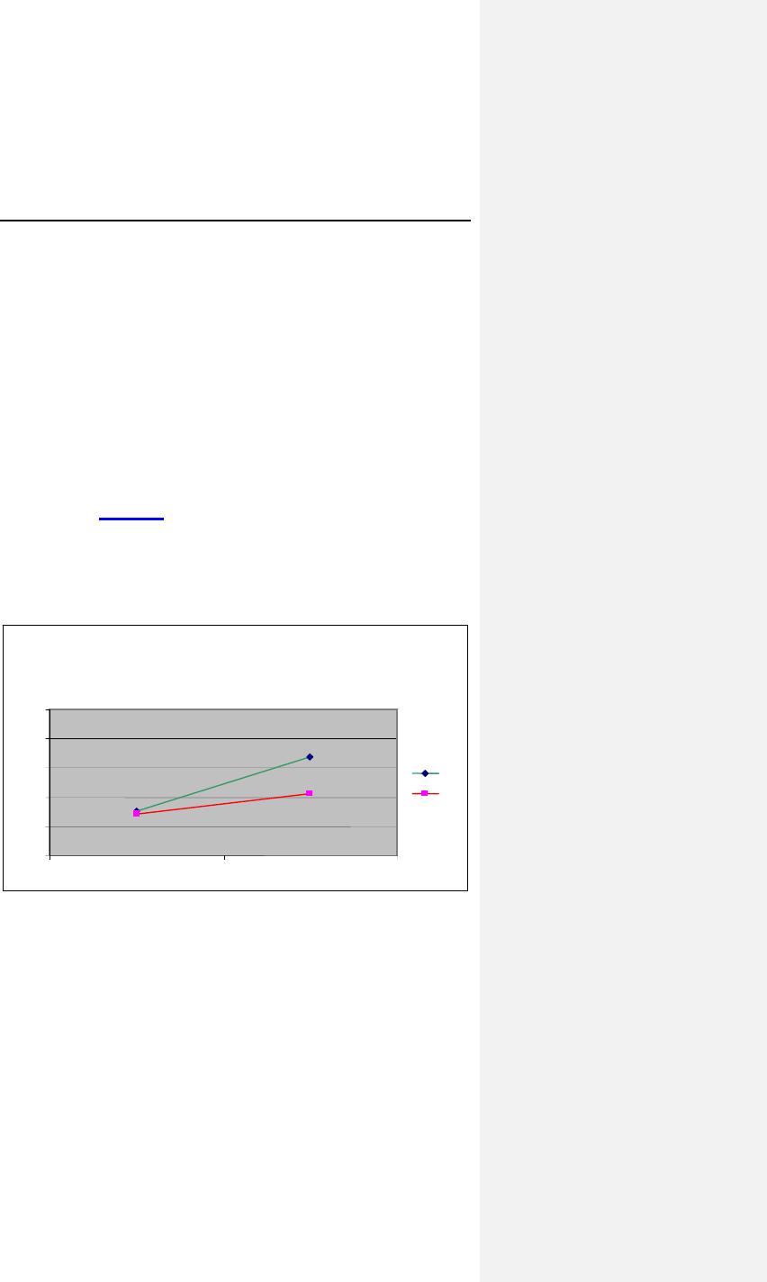
As shown in Figure 3, for these 40 subjects, the average heart
rate increased from 64.27 ± 4.8 bpm to 71.26 ± 5.4 bpm when
the pacemaker was programmed to an accelerometer pacing
mode during the ER Test©. For the same test, the average heart
rate increased from 65.24 ± 4.0 bpm to 83.90 ± 7.5 bpm when
the pacemaker was programmed to the CLS pacing mode.
Figure 3: Average Heart Rates at Baseline and during ER
Test©
Peak Heart Rates (n=40)
83.9
71.2
65.2
64.2
50
60
70
80
90
10
Restin ER Test
©
CL
R

38 Evia Technical Manual
The increase in heart rate in CLS mode was 18.65 ± 5.77 bpm
compared to 6.99 ± 3.22 bpm in the accelerometer mode. Using
the paired Student’s t-test, the p value was less than 0.001. The
null hypothesis was rejected.
6.3.1.4 Summary and Conclusions
• A total of 74 patients were enrolled at 16 medical
centers.
• The study analysis included forty (40) of those 74
patients who met the predefined criteria of at least 80%
sensor driven heart rates during the ER Test©.
• During the ER Test©, the average sensor driven heart
rate increase for CLS mode was 18.65 ± 5.77 bpm
versus 6.99 ± 3.22 bpm while in accelerometer mode, p
< 0.001.
• The mean heart rate increase from baseline associated
with the ER Test© for age group 40-60 years was 16.14
± 1.15 bpm and the age group 60+ years was 18.79 ±
5.89 bpm. The rate response provided by CLS is
consistent with those age matched healthy subjects in
the literature.
• CLS demonstrated an appropriate response to
myocardial contractility changes due to acute mental
stress.
• All 40 patients (100%) showed a higher peak heart rate
in the CLS pacing mode compared to the accelerometer
pacing mode.
• In conclusion, BIOTRONIK has shown the effectiveness
of the Protos DR/CLS pacemaker for providing
appropriate rate response as tested during an acute
mental stress test, the ER Test©, for patients exhibiting a
high percentage of sensor-driven pacing.
6.3.2 Protos DR CLS with AxVx
6.3.2.1 Primary Objectives
The clinical study included evaluation of the safety and
effectiveness of the device in patients with a high percentage of
ventricular sensing (80% or more) to demonstrate that the AxVx
version of CLS functions appropriately for this type of patients.

Evia Technical Manual 39
EFFECTIVENESS
The analysis was based on the simple linear regression
(y = m + ax) of the obtained rate-adaptive pacing rate versus the
expected heart rate during a CAEP treadmill test with the device
in patients with a high percentage of ventricular sensing (80% or
more).
SAFETY
This endpoint was based on the analysis of adverse events
(complications and observations) caused by the Protos CLS
devices during this acute study.
6.3.2.2 Methods
A total of 21 patients with previously implanted legally marketed
Protos DR CLS pulse generators were enrolled in a controlled,
prospective study. The investigation was conducted at 5 centers.
The average patient was a 70 year-old male, with sinus
bradycardia.
During a follow-up visit, the pacemakers were downloaded with
the AxVx investigational software. At a second follow-up, the
patient performed a symptom limited CAEP treadmill test.
Following the treadmill testing with the investigational AxVx
algorithm, the pacemaker was downloaded with legally marketed
AxVp software for routine follow-up care.
6.3.2.3 Results
EFFECTIVENESS
A total of 13 treadmills were included for the analysis of the rate
response slope. The mean rate response slope during the
CAEP treadmill test was 0.66 with standard deviation of 0.23 and
a 95% confidence interval of [0.52, 0.80].
The number and percentages of patients who met the predefined
performance criteria are presented in Table 7.
40 Evia Technical Manual
Table 7: Percentages of Patients Meeting Success Criteria
Criteria % Patients
Slope > 0.650 53.8% (7/13)
Within 20 bpm of MCLR* 69.2% (9/13)
Achieved MCLR 46.2% (6/13)
* MCLR = Maximum Closed Loop Rate
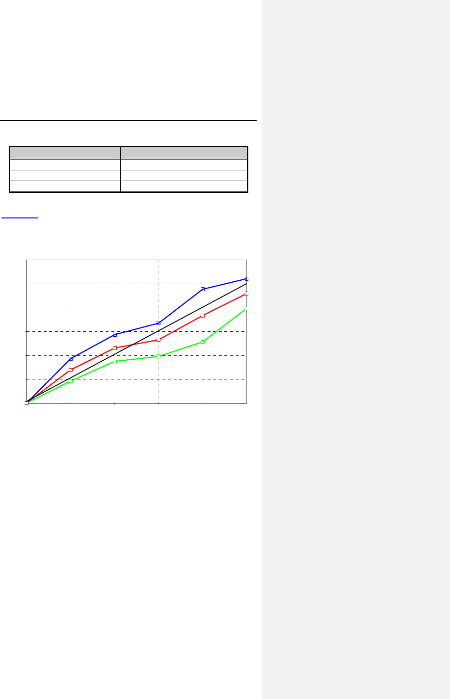
Figure 4 shows the obtained heart rate versus the expected
heart rate during the CAEP treadmill test for all patients
completing at least 3 stages of exercise (n = 13).
0.00
0.20
0.40
0.60
0.80
1.00
1.20
0.00 0.22 0.39 0.54 0.73 1.00
CAEP Workload (Normalized)
Obtained HR (normalized)
Wilkoff Predicted HR
Lower 95% CI
Mean (n = 13)
Upper 95% CI
Figure 4. Obtained vs. Expected Heart Rate during CAEP

Evia Technical Manual 41
SAFETY
There were no complications reported and there was only 1
observation reported; One patient reported feeling fatigued since
the reprogramming of his Protos pulse generator to AxVx. The
patient performed well during the CAEP treadmill, resulting in a
slope of 0.7. After the CAEP treadmill testing, his pacemaker
was reprogrammed to the settings before the AxVx download.
The calculated rate for observations is 0.05 observations per
patient which is within the clinically acceptable rate. This clinical
study demonstrates the overall safety profile of the AxVx
algorithm.
6.3.2.4 Clinical Study Conclusions
BIOTRONIK has shown that the Protos DR/CLS AxVx
rate-adaptive algorithm provides appropriate rate response as
tested during a symptom limited CAEP treadmill test for patients
exhibiting a high percentage of ventricular sensing (99.1% for
13 patients meeting the pre-defined analysis criteria).
6.3.3 Inos2+ CLS
6.3.3.1 Primary Objectives
The clinical study included evaluation of the safety and
effectiveness of the device.
6.3.3.2 Methods
A total of 129 patients were implanted with the Inos pulse
generator in a controlled, prospective study. The investigation
was conducted at 15 centers. The average patient was a
73 year-old male, with a NYHA Classification of I and Sinus
Bradycardia.
Each patient was followed at hospital discharge and at one,
three and six month post-implant and every 6 months thereafter.
At the one month follow-up a Chronotropic Assessment Exercise
Protocol (CAEP) treadmill test and a 24 hour Holter recording
were performed.

42 Evia Technical Manual
6.3.3.3 Results
SAFETY
The clinical study complication rate was 10.08% (13 out of 129
patients) versus the acceptance criterion of 11.5% (15 out of
129 patients). The clinical investigation did not classify any of
these complications as being related to the pulse generator.
EFFECTIVENESS
A total of 52 treadmills were included for the analysis of the rate
response slope. The mean rate response slope during the
CAEP treadmill test was 0.82 with a 95% confidence interval of
[0.75, 0.89]. These values meet the acceptance criterion for this
objective.
Table 8 compares several predicted heart rates to the obtained
rates as estimated by linear regression of the treadmill data. This
table shows that overall the patients reached about 95% of the
programmed maximum closed loop rate (MCLR) in the last
stages of exercise.
Table 8: Estimated Heart Rates
Predicted Heart
Rate (bpm) Obtained Heart
Rate (bpm) Ratio of Obtained
to Predicted (%)
60 68.13 113.6%
80 84.53 105.7%
100 100.93 100.9%
120 117.33 97.8%
140 133.73 95.5%
160 150.13 93.8%
The number and percentages of patients who met certain
performance criteria are presented in Table 9.
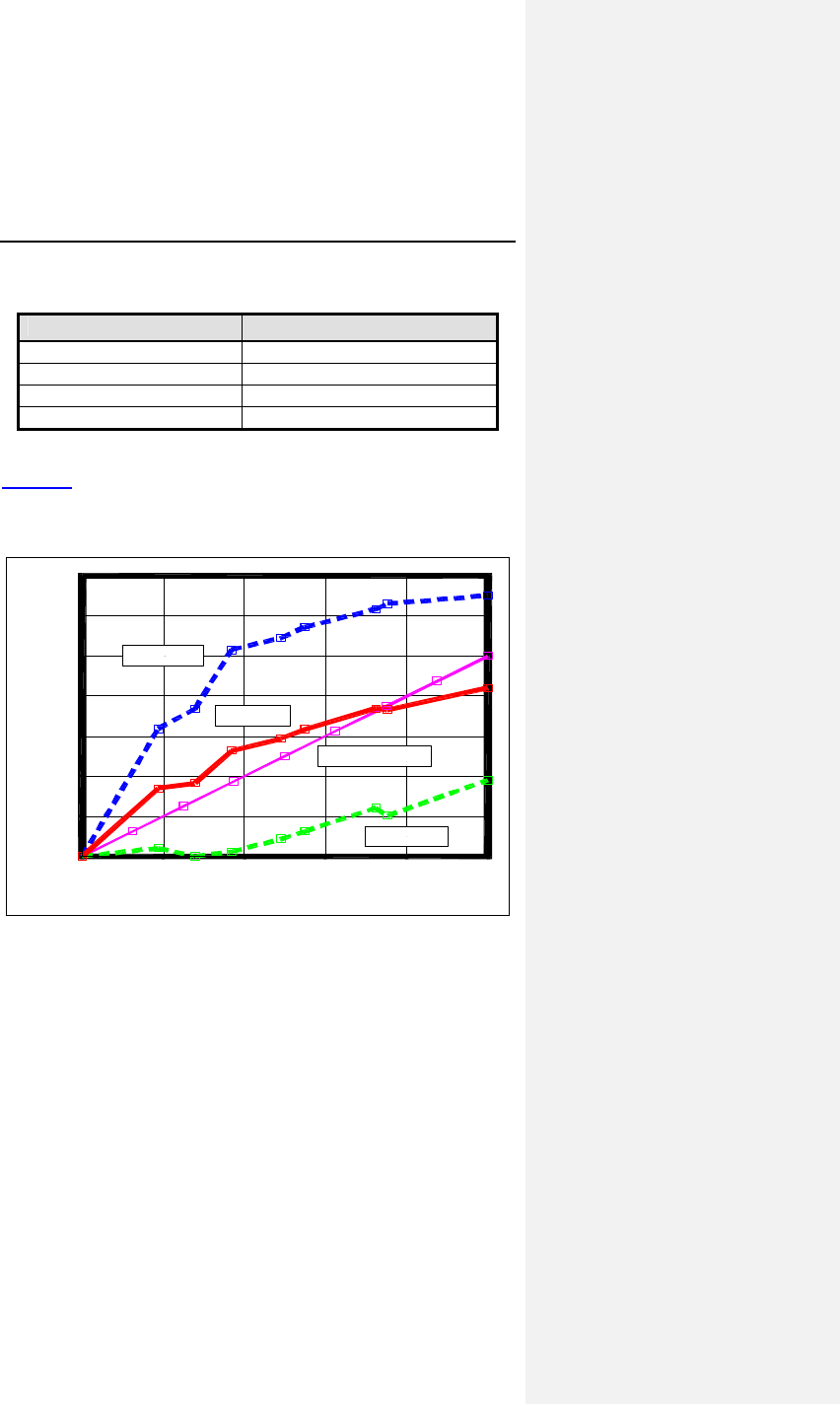
Evia Technical Manual 43
Table 9: Percentages of Patients Meeting Success Criteria
Criteria % Patients
Slope > 0.825 53.8% (28/52)
Slope > 0.650 78.8% (41/52)
Within 20 bpm of MCLR 80.8% (42/52)
Achieved MCLR 46.2% (24/52)
Figure 5 shows the obtained heart rate versus the expected
heart rate during the CAEP treadmill test for all patients
completing at least 4 stages of exercise (n = 52).
CAEP Workload (normalized)
1.0.8.6.4.20.0
Obtained Heart Rate (normalized)
1.4
1.2
1.0
.8
.6
.4
.2
0.0
Upper 95% CI
Lower 95% CI
Mean (n=52)
Expected Wilkoff HR
Figure 5. Obtained vs. Expected Heart Rate during CAEP

44 Evia Technical Manual
In addition to slope analysis, the treadmill performance was
evaluated by quantitatively comparing the obtained rates to the
predicted heart rate for each stage. In forty-six patients (88.5%)
the heart rate obtained at the different CAEP stages was nearly
equivalent to the predicted heart rate for each of the stages. The
average slope for this group was 0.83. Two patients (3.8%)
obtained heart rates at the different CAEP stages that were
significantly (15%) lower than the predicted heart rates in three
or more stages. The average slope for this group was 0.13. Four
patients (7.7%) obtained heart rates at the different CAEP
stages that were significantly (15%) higher than the predicted
heart rate in three or more stages. The average slope for this
group was 0.96.
6.3.3.4 Clinical Study Conclusions
The clinical data support that the Inos pacing system is safe and
effective for use in patients that are indicated for rate-adaptive
pacing. The Inos Clinical Study fulfilled the predefined primary
safety and efficacy endpoints. These endpoints included
appropriate obtained heart rates during exercise and
complication-free rate.
6.4 TRUST Clinical Study
6.4.1 Study Overview
The TRUST study is a multi-center, prospective and randomized
trial. The purpose of the study was to demonstrate that the use
of the BIOTRONIK Home Monitoring system (HM) can safely
reduce the number of regularly scheduled office follow up visits,
compared to the conventional method of ICD follow-up. The
assessment consists of comparing the number of in-office follow-
ups for patients with HM (HM group) versus patients without HM
(Control group). With the use of HM, the number of in-office
follow up visits per year could be reduced from an expected five
scheduled office follow up visits (3, 6, 9, 12 and 15 months) to
two visits (3 and 15 months). Additionally, the time from onset to
evaluation of arrhythmias in both groups was compared. It was
expected that evaluation of cardiac events in the HM arm would
occur earlier than those in the Control group.

Evia Technical Manual 45
6.4.2 Methods
All enrolled patients received a BIOTRONIK ICD with Home
Monitoring/IEGM-Online® technology and were randomized to
either Group 1 (Home Monitoring (HM)) or Group 2 (No Home
Monitoring (Control)) using a randomization ratio of 2:1.
Group 1 (HM)
Device evaluations for scheduled follow-ups, patient-initiated
inquiries and event triggered notifications were performed with
HM/IEGM Online. Patients were scheduled for office device
interrogations only at the 3 month and 15 month follow-up points
(following the HM online check). At 6, 9 and 12 months, a HM
check was performed first. Investigators may then elect to
perform an office device interrogation if they determine that it is
necessary after reviewing the HM data.
Group 2 (Control)
Patients were evaluated using conventional, calendar-based
office visits at 3, 6, 9, 12 and 15 months post-implant. Interim
visits were made according to physician discretion (e.g. following
any ICD discharges or symptoms). Home Monitoring was to be
programmed OFF for the duration of the study.
HM Event Triggered Device Evaluations
Investigators with patients in Group 1 (HM) may receive HM
notifications in response to pre-programmed events such as VT1
detected and SVT detected. Upon the receipt of a HM Event
Notification, investigators reviewed the notification and the
associated information on the HM/IEGM-Online website and
recorded the type of event and what type of action, if any, was
taken as a result of this notification.
Patient-Initiated Device Evaluations
Investigators may be contacted by the patient for
device/arrhythmia-related care (e.g. perceived device discharge,
symptoms). For patients in Group 1 (HM), investigators triaged
the complaint using the Home Monitoring website. Investigators
recorded if the information from Home Monitoring was sufficient.
For patients in Group 2 (Control), the complaint was assessed
per standard of care or normal clinic procedures.

46 Evia Technical Manual
Primary Endpoints
The purpose of primary endpoint 1 (HM efficacy) was to
compare the number of in-office ICD follow-ups for patients in
Group 1 (HM) to the conventional, calendar-based method of
ICD follow-up as in Group 2 (Control).
The purpose of the primary endpoint 2 (safety) was to compare
the Safety Event Rate (SER), which includes death, incidence of
strokes and events requiring surgical interventions (e.g. device
explants or lead revision) between the two groups.
Secondary Endpoints
The purpose of secondary endpoint 1 was to compare AF, VT
and VF events between Group 1 and Group 2 in terms of the
number, categories, and detection time relative to onset.
Inclusion Criteria
To support the objectives of this investigation, the inclusion
criteria at the time of patient enrollment for this investigational
study included the following requirements:
• Implanted within the last 45 days or being considered for
implant with a BIOTRONIK ICD with Home
Monitoring/IEGM-Online technology
• Able to utilize the HM system throughout the study
• Ability to give informed consent
• Geographically stable and able to return for regular
follow-ups for fifteen (15) months
• At least 18 years old
Exclusion Criteria
To support the objectives of this investigation, the exclusion
criteria at the time of patient enrollment included the following
requirements:
• Patients who do not fulfill all inclusion criteria
• Patients who are pacemaker dependent
• Currently enrolled in any other cardiac clinical
investigation.

Evia Technical Manual 47
Clinical Events Committee
The Clinical Events Committee (CEC) is an advisory review
board comprised of three physicians that are not participating in
the TRUST Study who reviewed and adjudicated all deaths,
strokes, surgical interventions, and cardiac adverse events that
occur during the study. The CEC also reviewed all divergent
classifications of actionable vs. non-actionable office follow up
visits between the physician and BIOTRONIK, and reviewed a
random sampling of 1% of office follow up visits in which there is
no disputed classification.
6.4.3 Summary of Clinical Results
The study involved 1443 patients (1038 males, 71.9%), with a
mean age of 63.5 years (range: 20-95). The cumulative
enrollment duration is 18,367 months with mean enrollment
duration of 12.7 months. The patient follow-up compliance rate
for all enrolled patients is 87.5% in Group 1 and 78.8% in
Group 2.
6.4.3.1 Primary Endpoint 1: Home Monitoring
Effectiveness
The purpose of primary endpoint 1 (HM efficacy) was to
compare the number of in-office ICD follow-ups for patients in
Group 1 (HM) to the conventional, calendar-based method of
ICD follow-up as in Group 2 (Control).
Detailed primary endpoint 1 results are presented in Table 10.
Table 10: Primary Endpoint Group 1 vs. Group 2
No. of
Pts**
Office Follow-up Visits
Scheduled Unscheduled Total
Group 1
(HM) 898
n = 991
1.3 ± 1.0 per pt yr
13.1% actionable
n = 401
0.6 ± 1.7 per pt yr
29.7% actionable
1.9 ± 1.9
per pt yr
Group 2
(Control) 414
n = 1110
3.0 ± 1.1 per pt yr
10.7% actionable
n = 117
0.4 ± 1.4 per pt yr
29.1% actionable
3.4 ± 1.7
per pt yr
p value < 0.001 0.032
< 0.001
* Up to and including 12 month follow-up data
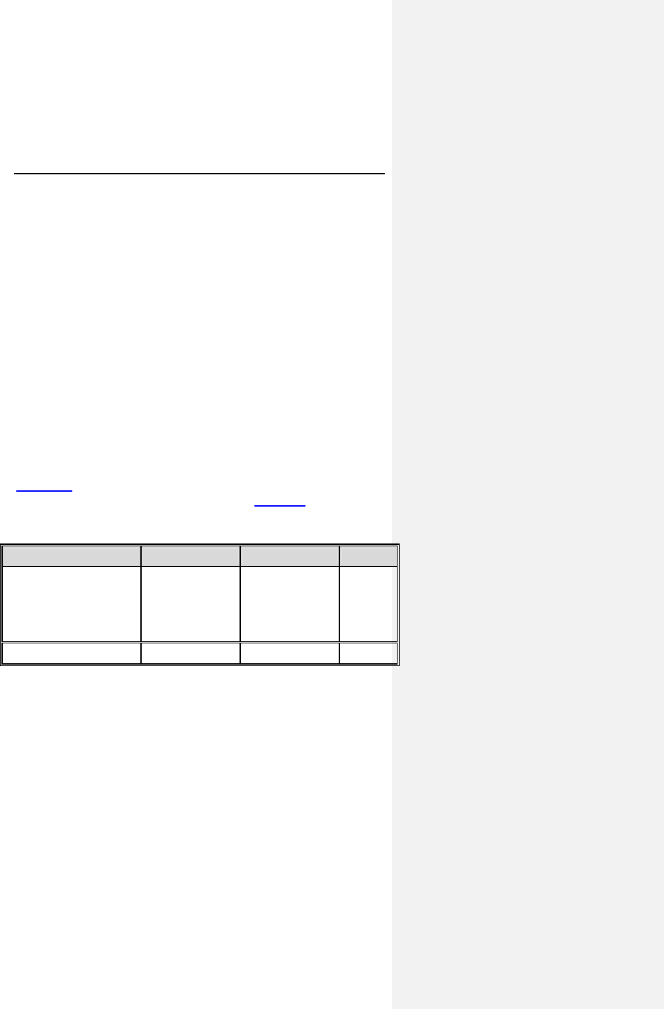
48 Evia Technical Manual
** Number of patients that have contributed at least 1 follow-up
Analysis
The comparison of the number of 3, 6, 9, and 12 month and
unscheduled office follow-up visits in Group 1 versus Group 2
showed that there was an average number of 1.9 office follow-up
visits on a per year basis in Group 1 (HM) and an average
number of 3.4 office follow-up visits on a per year basis in Group
2 (Control). Therefore, the null hypothesis (HØ) can be rejected,
indicating that the average number of office visits per year is
statistical significantly less in the HM group than in the Control
group (p < 0.001). The primary effectiveness endpoint was met.
6.4.3.2 Primary Endpoint 2: Safety Event Rate
The purpose of the primary endpoint 2 was to compare the
Safety Event Rate (SER), which includes death, incidence of
strokes and events requiring surgical interventions (e.g. device
explants or lead revision) between the two groups.
Table 11 summarizes the Safety Event Rate for the study
patients for 12 months post-enrollment. Figure 6 shows these
data in a Kaplan-Meier analysis.
Table 11: Safety Event Rate Comparison
Safety Event Rate* Group 1 Group 2 p value**
Type of Event
Death
Stroke
Surgical
intervention
36 / 608 (5.9%)
2 / 574 (0.3%)
57 / 605 (9.4%)
18 / 245 (7.3%)
3 / 227(1.3%)
22 / 239 (9.2%)
0.440
0.141
1.000
Any Event 95 / 643 (14.8%) 42 / 256 (16.4%) 0.539
* Only includes events occurring within 12 months of enrollment
** 2-sided Fisher Exact test
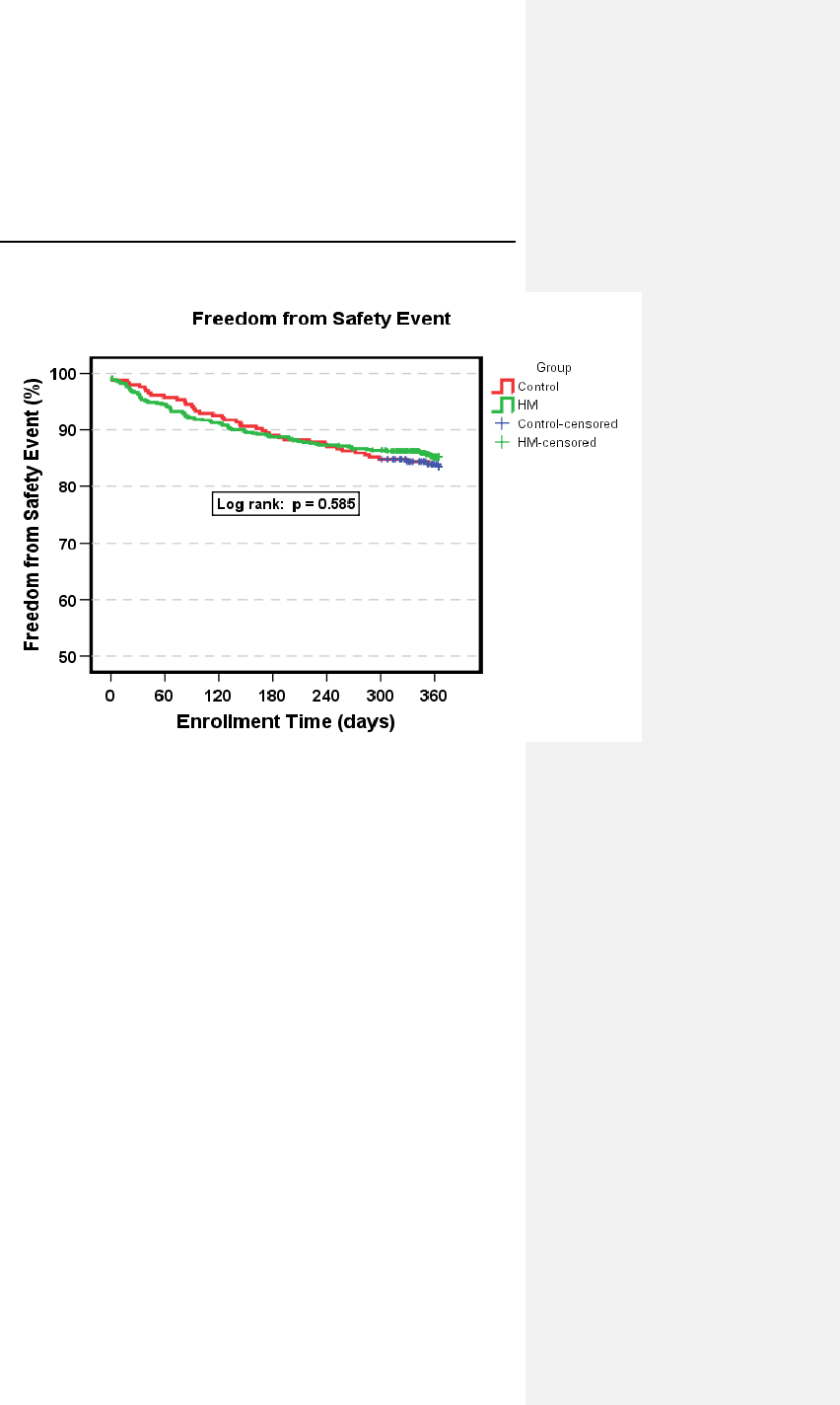
Evia Technical Manual 49
Figure 6: Safety Event Rate Kaplan Meier
Analysis
The safety event rate for a 12-month duration was 14.8% for
Group 1 (HM) and 16.4% for Group 2 (Control), with a
non-inferiority p-value of 0.005. Therefore, the safety event rate
for HM Group was non-inferior to the safety event rate for the
Control Group within 5%. The upper, one-sided 95% confidence
bound for the difference was 2.7%.
A rejection of the null hypothesis indicates that the safety event
rate for Group 1 (HM) is equivalent (non-inferior) to that of
Group 2 (Control).
6.4.3.3 Secondary Endpoint 1: Early Detection of
Cardiac Events (AF, VT & VF)
The purpose of secondary endpoint 1 was to compare AF, VT
and VF events between Group 1 and Group 2 in terms of the
number, categories, and detection time relative to onset.

50 Evia Technical Manual
Table 12 compares the time from onset to evaluation of the first
AF, VT and VF events for each patient that have occurred in
each group, as well as the first of any type of event for each
patient in each group. Figure 7 illustrates the time from onset to
evaluation of arrhythmic events in a boxplot graph.
Table 12: Time from First Event Onset to Evaluation
Time from Event Onset
to Evaluation of First
Event/Patient
Group 1
N=972 Group 2
N=471 p value
A
F
Median
Mean ± SD (days)
Min
Max
# of patients with events
5.0
25.2 +/- 34.2
0
171
73 (7.5%)
39.5
46.8 +/- 33.7
1
114
28 (5.9%)
p < 0.001
p = 0.005
V
T1 &
V
T2
Median
Mean ± SD (days)
Min
Max
# of patients with events
2.0
12.9 +/- 33.8
0
256
149 (15.3%)
32.0
46.6 +/- 46.9
0
245
53 (11.2%)
p < 0.001
p < 0.001
V
F
Median
Mean ± SD (days)
Min
Max
# of patients with events
1.0
10.5 +/- 22.2
0
145
236 (24.3%)
35.5
45.0 +/- 47.0
0
287
92 (19.5%)
p < 0.001
p < 0.001
SVT
Median
Mean ± SD (days)
Min
Max
# of patients with events
2.0
16.6 ± 27.4
0
108
94 (9.7%)
39.0
42.1 ± 35.6
0
157
35 (7.4%)
p < 0.001
p < 0.001
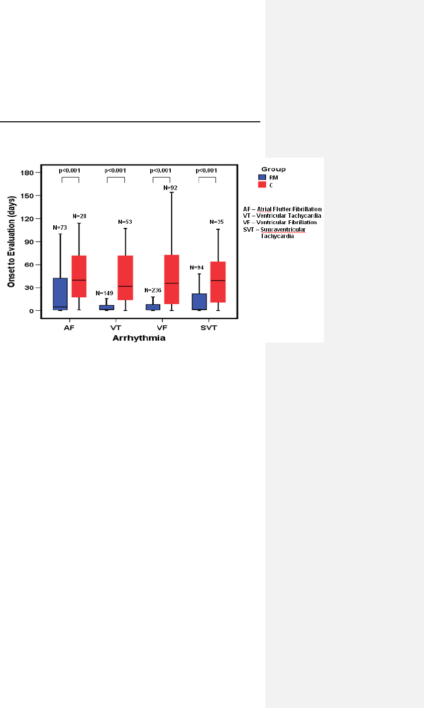
Evia Technical Manual 51
Figure 7: Median Time from Onset to Evaluation of
Arrhythmic Events
Analysis
The mean time from onset to evaluation of first AF, VT, and VF
events in Group 2 is greater than the mean time from onset to
evaluation of first AF, VT, or VF events in Group 1. A rejection
of the null hypothesis for AF, VT and VF event types indicates
that the mean time from onset to evaluation of the first AF, VT
and VF events in Group 1 is significantly less than the mean time
from onset to evaluation of the first AF, VT and VF events in
Group 2. P-values are =0.005, <0.001 and <0.001 respectively.
6.4.4 Conclusions
• Use of HM in Group 1 resulted in an average of 1.9 office
visits per patient year in the 12 months post-implant, versus
an average of 3.4 office visits per patient year in Group 2, a
44% reduction in office visits. The average number of office
visits is significantly less in the HM group than in the Control
group (p < 0.001).

52 Evia Technical Manual
• The safety event rate for a 12 month duration for Group 1
(HM) was non-inferior to the safety event rate for Group 2
(Control) within 5% (p = 0.005). The upper, one-sided 95%
confidence bound for the difference was 2.7%.
• The mean time from onset to evaluation of AF, VT and VF
events indicates that those events for Group 1 patients are
evaluated in significantly less time when compared to Group
2 patients (AF p = 0.005, VT p < 0.001, VF p < 0.001).

Evia Technical Manual 53
7. Programmable Parameters
For a complete list of programmable parameters and the
available settings, see Section 15.
7.1 Pacing Modes
For a complete list of pacing modes available in each Evia
configuration, see Section 15.1.
NOTE:
Ventricular Capture Control is only available with the
following pacing modes: DDD-CLS, VVI-CLS, DDDR,
VDDR, VVIR, VVI, DDD, and VDD.
7.1.1 Motion Based Rate-Adaptive Modes
The motion based rate-adaptive modes are designated with a
“R” in the fourth position of the NBG pacemaker code on the
programmer screen. The rate-adaptive modes function
identically to the corresponding non-rate-adaptive modes, except
that the basic rate increases when physical activity is detected
by the motion sensor.
In demand modes (DDDR, DDIR, DVIR, VDDR, VVIR, AATR,
VVTR, VDIR, AAIR), it is possible that the atrial and/or
ventricular refractory period can comprise a major portion of the
basic interval at high sensor-modulated rates. This may limit the
detection of spontaneous events or even exclude their
recognition altogether. Further details of this potential
occurrence are provided in Section 7.5.1.
7.1.2 CLS Modes
As explained in the device description, Evia also can be
programmed to use a unique rate-adaptive principle called
Closed Loop Stimulation (CLS) to adapt the patient’s pacing
rate.

54 Evia Technical Manual
The Evia measures electrical impedance by injecting a small AC
current between the pulse generator case and the ventricular
electrode tip. The induced voltage (which is proportional to the
intracardiac impedance) is also measured between pulse
generator case and ventricular electrode tip.
CAUTION
Rate-Adaptive Pacing – Use rate-adaptive pacing with care
in patients unable to tolerate increased pacing rates.
CLS Rate Adaptation – Under certain circumstances (e.g.,
EMI, lead dislodgment), the Evia device may not be able to
obtain a useable impedance measurement as required for
CLS rate-adaptive pacing. At this point, CLS rate-adaptation
will be inactive until the situation is corrected. Rate-adaptation
may be programmed to switch to motion based adaptation.
The DDD-CLS and VVI-CLS mode is functionally equivalent to
the DDDR and VVIR pacing modes, respectively. However
these modes use the CLS concept to determine the pacing rate
variations that are mediated by the body’s own cardiovascular
control. In these modes, the atrial and/or ventricular refractory
periods may comprise a major portion of the basic interval at
high rates. This could limit the detection of spontaneous events
or even exclude their recognition altogether. However, this
phenomenon will not limit the functionality of the mode switch.
Motion based rate adaptive pacing will take over if the CLS
pacing algorithm switches into a passive mode.
7.1.3 Non-Rate-Adaptive Modes
Non-rate-adaptive modes that are programmable with the Evia
pacemaker perform similarly to earlier generations of
BIOTRONIK pulse generators (i.e., Philos II DR and
Dromos DR).

Evia Technical Manual 55
7.1.4 Mode Switching
Evia provides Mode Switching to change pacing modes as a
result of atrial tachycardias. Mode Switching is designed to
avoid tracking of non-physiologic atrial rates due to paroxysmal
atrial tachycardias (PATs). Mode Switching is only available in
atrial tracking modes DDD(R), VDD(R), and DDD-CLS
Mode Switching
The Mode Switching algorithm causes the pulse generator to
change pacing modes when a programmed number of atrial
intervals (X) out of 8 consecutive atrial intervals (p-p) are faster
than the programmed mode switch intervention rate (X out of 8).
X is programmable from 3 to 8. The rate at which an atrial
interval is determined to signify an atrial tachyarrhythmia is
called the mode switch intervention rate. The mode switch
intervention rate is programmable from 100 to 250 bpm. A Mode
Switch Basic Rate can be programmed to allow for a higher
basic rate during an active Mode Switch, in order to diminish
undesirable hemodynamic behaviors.
The mode switch occurs from atrial tracking to non-atrial tracking
pacing modes (e.g. DDDR to DDIR) as described in Table 13.
Reversion back to the programmed pacing mode occurs in a
similarly programmable manner. If a programmable number of
atrial intervals (Z) out of 8 consecutive atrial intervals (p-p) are
slower than the programmed mode switch intervention rate
(Z out of 8), the device will revert back to the permanently
programmed parameters. Z is programmable from 3 to 8. The
device will also revert back to the permanent program if no atrial
paced or sensed events have occurred for at least 2 seconds.
Additionally, during DDI(R), the AV-delay is set to 100 ms.
Mode Switch Events are recorded in memory and are available
to the user through the following diagnostics:
• IEGM Recordings Found in the Holter Tab
• Mode Switch Counter
• Total Mode Switch Duration
Mode Switching is available during magnet application after 10
cycles of ASYNC pacing and during ERI. Mode Switching occurs
as described in Table 13.

56 Evia Technical Manual
Table 13: Programmable Mode Switches
Programmed
Pacing Mode Programmable Mode Switch
Pacing Modes
Rate-Adaptive Non-Rate-
A
daptive
DDDR and
DDD-CLS
DDIR N/A
VDDR VDIR N/A
DDD DDIR DDI
VDD VDIR VDI
7.1.5 Pacing Modes with Triggered Response
Pacing modes with triggered response correspond to their
respective demand pacing modes, except that a sensed event
will not inhibit but will rather trigger a pacing pulse,
simultaneously with the sensed event, into the same chamber
where sensing has occurred. The demand and corresponding
triggered pacing modes are:
Demand: DDD VVI AAI
Triggered: DDT VVT AAT
The triggered pacing mode fixes the AV delay to 180 ms and
does not provide a safety AV delay.
Pacing modes with triggered response may be indicated in the
presence of interference signals to prevent inappropriate pulse
inhibition. They may also have diagnostic application for ECG
identification of sense events as an alternative to marker signals.
Triggered pacing may also be used for hemodynamic as well as
electrophysiologic studies and for termination of tachycardias by
non-invasive triggering of pulse generator pulses with chest wall
stimuli generated by an external pulse generator.

Evia Technical Manual 57
CAUTION
Programmed to Triggered Modes – When programmed to
triggered modes, pacing rates up to the programmed upper
limit may occur in the presence of either muscle or external
interference.
Triggered Modes – While the triggered modes (DDT, VVT,
and AAT) can be programmed permanently, the use of these
modes is intended as a temporary setting in situations where
maintaining the programming head in place would be
impossible or impractical (i.e., during exercise testing or
extended Holter monitoring) or as a short term solution to
pulse generator inhibition by extracardiac interference. To
avoid the potential for early battery depletion, it is important
that the triggered modes are not used for long term therapy,
and that the pulse generator is returned to a non-triggered
permanent program.
7.2 Rate Related Functions
The availability of parameters and parameter values is
determined by the software used for programming/ interrogating
the pulse generator.
7.2.1 Basic Rate
The basic rate is the pacing rate in the absence of a
spontaneous rhythm and is programmable up to 200 ppm.
CAUTION
Programming Modifications – Extreme programming
changes should only be made after careful clinical
assessment. Clinical judgment should be used when
programming permanent pacing rates below 40 ppm or above
100 ppm.

58 Evia Technical Manual
7.2.2 Rate Hysteresis
Hysteresis can be programmed OFF or to values as low as
-5 bpm and as high as -90 bpm. The Hysteresis rate is based on
the lower rate and the value of the programmable parameter.
Hysteresis is initiated by a sensed event. The resulting
Hysteresis rate is always less than the lower rate. A conflict
symbol will appear and transmission will be prohibited for
Hysteresis rates which are less than 30 bpm. The ability to
decrease the effective lower rate through Hysteresis is intended
to preserve a spontaneous rhythm. The pulse generator
operates by waiting for a sensed event throughout the effective
lower rate interval (Hysteresis interval). If no sensed event
occurs, a pacing pulse is emitted following the Hysteresis
interval.
NOTE:
If rate adaptation is active, the Hysteresis rate is based on
the current sensor-indicated rate and the value of the
programmable parameter.
Hysteresis is not available in CLS or DVI, and DVIR modes.
If Hysteresis is used in the DDI mode, the AV delay must be
programmed shorter than the spontaneous AV conduction
time. Otherwise, stimulation in the absence of spontaneous
activity occurs at the hysteresis rate instead of the lower
rate.
During night mode the rate will not fall below the
programmed night rate even if Hysteresis can take it to a
lower rate. Programming conflicts arise when the total
decrease in rate is below 30 ppm. Care should be exercised
to avoid programming a Night Mode rate and hysteresis that
is below what is appropriate and may be tolerated by the
individual patient.
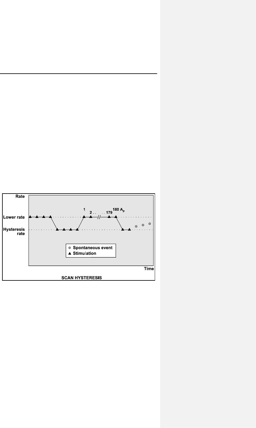
Evia Technical Manual 59
7.2.3 Scan Hysteresis
Scan hysteresis is expanded programmability of the Hysteresis
feature. Scan hysteresis searches for an underlying intrinsic
cardiac rhythm, which may exist slightly below the programmed
lower rate (or sensor-indicated rate) of the pulse generator.
Following 180 consecutive paced events, the stimulation rate is
temporarily decreased to the hysteresis rate for a programmed
number of beats. If a cardiac rhythm is not detected within the
programmed number of beats at the hysteresis rate, the
stimulation rate returns back to the original lower rate (or sensor-
indicated rate). Several programmable beat intervals are
available to allow a greater probability of detecting a
spontaneous rhythm.
If an intrinsic cardiac rhythm is detected within the programmed
number of beats between the hysteresis rate and the lower rate,
the intrinsic rhythm is allowed and the pulse generator inhibits.
Figure 8. Scan Hysteresis
Scan hysteresis has been incorporated to promote intrinsic
cardiac rhythm and may reduce pulse generator energy
consumption.
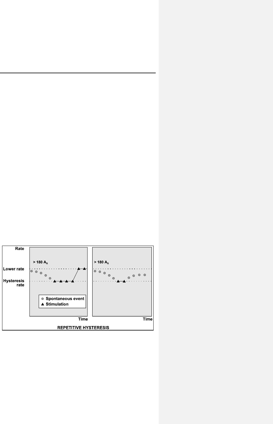
60 Evia Technical Manual
NOTE:
Scan Hysteresis can be used during night mode, but it will
not take the rate below the programmed night rate.
Scan Hysteresis is only available when Hysteresis is
selected on.
After the ASYNC effect following magnet application,
hysteresis is available.
7.2.4 Repetitive Hysteresis
Repetitive hysteresis is expanded programmability of the
Hysteresis feature. Repetitive hysteresis searches for an
underlying intrinsic cardiac rhythm, which may exist slightly
below the programmed lower rate (or sensor-indicated rate) of
the patient. Following 180 consecutive sensed events, this
feature allows the intrinsic rhythm to drop to or below the
hysteresis rate. During the time when the intrinsic rate is at or
below the hysteresis rate, pacing occurs at the hysteresis rate
for the programmed number of beats (up to 15). Should the
number of programmed beats be exceeded, the stimulation rate
returns to the lower rate (or sensor-indicated rate).
If an intrinsic cardiac rhythm is detected within the programmed
number of beats between the hysteresis rate and the lower rate,
the intrinsic rhythm is allowed and inhibits the pulse generator.
Figure 9. Repetitive Hysteresis

Evia Technical Manual 61
Repetitive hysteresis has been incorporated to promote
spontaneous cardiac rhythm and may reduce pulse generator
energy consumption.
NOTE:
Repetitive Hysteresis can be used during night mode but it
will not take the rate below the programmed night rate
Repetitive Hysteresis is only available when Hysteresis is
selected on.
There is one Standard Hysteresis interval which occurs
before the programmable number of Repetitive Hysteresis
occur.
7.2.5 Night Mode
Programmable Night Time Begin and End in 10 minute steps.
The Night Mode feature allows a temporary reduction of the
base rate during normal sleeping hours. If selected, the base
rate is gradually and temporarily reduced to the programmed
night pacing rate. At the end of night mode, the base rate
gradually returns to the original values.
The Night Mode feature has been incorporated to allow the
patient’s spontaneous night rhythm and may reduce pulse
generator energy consumption.
NOTE:
When Night Mode and Ventricular Capture Control are
programmed ON simultaneously in VVI(R), VCC will not take
the rate below the programmed night rate
Over time, the pulse generator’s internal time-of-day clock
will exhibit a discrepancy with the actual time (less than 1
hour per year). This will cause a corresponding discrepancy
between the programmed bed and wake times and the
actual times that the system changes the rate.
The programmer automatically updates the pulse generator
time-of-day clock each time the pulse generator is
programmed.
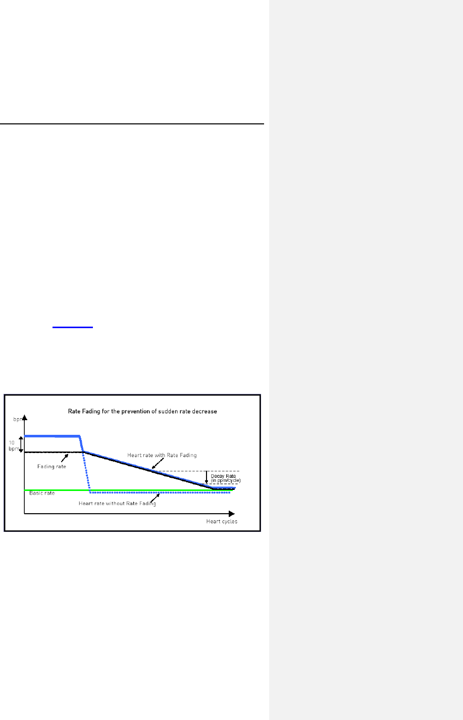
62 Evia Technical Manual
The actual time when the respective increase or decrease in
rate occurs may begin up to 4 minutes after the programmed
time because of internal pulse generator timing.
7.2.6 Rate Fading
Rate Fading is intended to prevent a sudden drop in heart rate
when the pulse generator transitions from tracking an intrinsic
rhythm to pacing due to an abrupt decrease in the intrinsic rate,
in order to prevent potential reactions such as dizziness, light
headedness, lack of energy and fainting.
With Rate Fading enabled, the pulse generator calculates the
Fading Rate, which is a four beat average of the intrinsic rate
reduced by 10 ppm. When the intrinsic rate drops considerably
(below the Fading Rate), the pacing rate begins at the RF rate
and then decreases gradually by the programmable Decay Rate
to the Sensor Indicated Rate or Basic Rate. This behavior is
illustrated in Figure 10.
NOTE:
The Fading Rate cannot exceed the programmed Maximum
Activity Rate and cannot increase faster than the RF Rate
decrease (programmable in ppm/cycle).
Figure 10: Rate Fading
The Rate Fading feature is available after 10 ASYNC while in
magnet mode and disabled at ERI and in backup mode.

Evia Technical Manual 63
7.3 Pulse Specific Features
Features related to the pacing pulse.
7.3.1 Pulse Amplitude
The programmed pulse amplitude determines the voltage
applied to the heart during each pacing pulse. The pulse
amplitude is independently programmable for the atrial and
ventricular channels up to 7.5 volts. The pulse amplitude
remains consistent throughout the service life of the pulse
generator. The pacing safety margin is therefore not reduced by
a decrease in the pulse generator's battery voltage.
NOTE:
When VCC is programmed to ON or ATM, the pulse
amplitude cannot be programmed by the user to a value
higher than the programmed Maximum VCC Amplitude
(Max. Ampl.). When VCC is programmed to ON, the pulse
amplitude will be set by the device to the threshold plus the
programmed Safety Margin, but never lower than the
Minimum VCC Amplitude (fixed at 0.7V.)
CAUTION
Pulse Amplitude – Programming of pulse amplitudes, higher
than 4.8 V, in combination with long pulse widths and/or high
pacing rates can lead to premature activation of the
replacement indicator. If a pulse amplitude of 7.0 V or higher
is programmed and high pacing rates are reached, output
amplitudes may differ from programmed values.
Programming Modifications – Extreme programming
changes should only be made after careful clinical
assessment. Clinical judgment should be used when
programming permanent pacing rates below 40 ppm or above
100 ppm.

64 Evia Technical Manual
7.3.2 Pulse Width
The selected pulse width determines the duration for which the
programmed pulse amplitude will be applied to the heart. The
pulse width is independently programmable (up to 1.5 ms) for
the atrial and ventricular channels. Pulse width remains
constant throughout the service life of the pulse generator.
NOTE:
When VCC is programmed to ON or ATM, the pulse width
cannot be programmed to a value higher than 0.4 ms.
7.4 Automatic Sensitivity Control (ASC)
The parameter “sensitivity” is used to set the pulse generator’s
threshold for detecting intracardiac signals. The lower the
programmed sensitivity values the higher the device’s sensitivity.
If intracardiac signals are of low amplitude, a change to a higher
sensitivity (lower value) may be indicated. Conversely, if the
sensing amplifier is responding to extraneous signals, such as
artifacts or interference, a change to a lower sensitivity (higher
value) may resolve the difficulty. The sensitivity values for the
atrial and ventricular channels are independently programmable
or automatic sensing control can be utilized. With Unipolar
programming, the highest possible sensitivity setting is 0.5 mV.
The Automatic Sensitivity Control (ASC) feature allows the pulse
generator to automatically measure the peak amplitude of a
sensed event and adapts the sensing threshold accordingly.
After each sensed detection (electrogram is above actual
threshold for 2 consecutive samples) the ASC is starting the
detection hold-off period of 121 ms in the ventricle (atrium 101
ms) and detects within the first 80 ms of this interval the highest
amplitude of the peak. After this initial period, the sensing
threshold is first set to 50% of the measured peak amplitude.
After the step duration of 125 ms the threshold is set to 25% of
the peak amplitude (atrium 82 ms) but never below the minimum
threshold of 2.5 mV in the ventricle (atrium 0.2 mV bipolar and
0.5 mV unipolar).

Evia Technical Manual 65
7.5 Timing Features
Features related to pulse generator timing cycles.
7.5.1 Refractory Periods
Immediately upon sensing or pacing, the pulse generator starts a
refractory period in the same channel. During the refractory
period, intracardiac signals are ignored. This prevents the pulse
generator from responding to the depolarization signal or the
repolarization signal (T-wave) that might otherwise result in
inappropriate inhibition or triggering.
If the pulse generator is programmed to dual chamber sensing,
the refractory periods are independently programmable for each
sensing channel. There are two refractory periods in the atrium:
• Regular atrial refractory period, which is automatically
adjusted by the Auto Aref functionality
• PVARP is started with each ventricular pace outside of
the AV delay. In DDI mode, PVARP is also started with a
regular ventricular sense
• PVARP after PVC is started after a premature
ventricular sensed event (PVC)
Far-field protection is activated in the atrium for ventricular
sensed and paced events. The pulse generator's ventricular
refractory period is always initiated by a sensed or paced
ventricular event.
CAUTION
Short Pacing Intervals – Use of short pacing intervals (high
pacing rates) with long atrial and/or ventricular refractory
periods may result in intermittent asynchronous pacing and,
therefore, may be contraindicated in some patients.
7.5.2 PVARP
The Post Ventricular Atrial Refractory Period (PVARP) is a
function in the pacemaker to help prevent Pacemaker Mediated
Tachycardia (PMT), by preventing false classification of a
retrograde conduction as an atrial event.
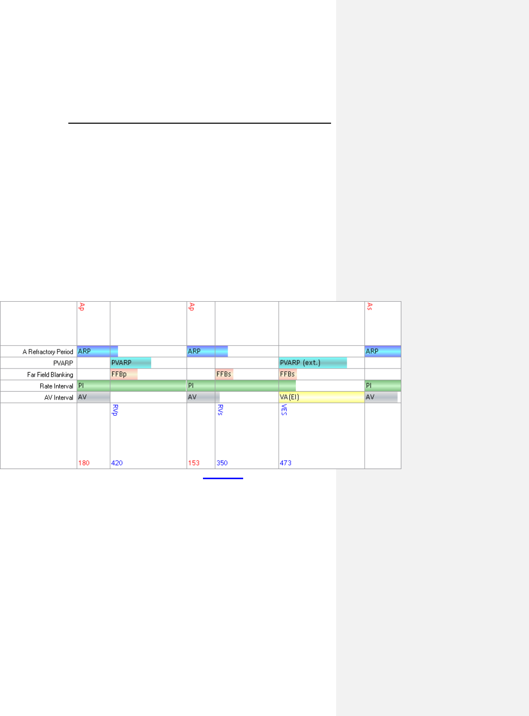
66 Evia Technical Manual
There are 2 different behavior modes of PVARP based on
programmed mode, which is described below.
• In P-synchronous modes (e.g. DDD), the PVARP timer
is started after : Vp, Vp(WKB), Vp(SW), Vp(BU)
• In R-synchronous modes (e.g. DDI), the PVARP timer is
started after: Vp, Vp(SW), Vp(BU), VES, Vs and
Vs(AVC).
• After a VES, the parameter PVARP after PVC is
automatically extended to PVARP + 150ms, up to a
maximum of the user programmable “PMT VA Criterion
limit” + 50 ms. This parameter was formerly known as
PMT protection after PVC.
This behavior is demonstrated in Figure 11.
Figure 11: PVARP Timing

Evia Technical Manual 67
Table 14 shows the PVARP parameter values and ranges.
Table 14: PVARP Parameter Values and Ranges
Parameter
Name Range Standard Value Units
PVARP AUTO, 175..(5)..600 AUTO ms
PVARP
after PVC
PVARP + 150ms 400ms ms
7.5.2.1 AUTO PVARP
If the PVARP feature is set to AUTO, the algorithm optimizes the
PVARP to reduce the incidence of PMT. The nominal values of
PVARP value is set to 250ms, and PVARP after PVC is set to
400ms. Once a PMT is detected, the algorithm automatically
extends the PVARP and PVARP after PVC by 50ms, up to the
maximum value of 600ms.
If there is no PMT detected by the algorithm, both the PVARP
and PVARP after PVC is reduced by 50ms every 7 days, but no
less than the minimum value of 175ms.
7.5.3 AV Delay
7.5.3.1 Dynamic AV Delay
The AV delay defines the interval between an atrial paced or
sensed event and the ventricular pacing pulse. If the pulse
generator is programmed to a dual chamber sensing mode, an
intrinsic ventricular event falling within the AV delay will inhibit
the ventricular pacing pulse. If not contraindicated, a longer AV
delay can be selected to increase the probability of ventricular
output pulse inhibition. Short AV delays are available for testing
purposes or if ventricular pre-excitation is desired (i.e.,
hemodynamic considerations).

68 Evia Technical Manual
Dynamic AV Delay provides independent selection of AV Delays
from five rate ranges at pre-set AV Delay values. In addition, the
AV Delay after atrial pace events can be differentiated from the
AV interval after atrial sense events for dual chamber pacing
modes. Dynamic AV Delay is programmable within the following
atrial rate ranges at the values specified in Table 15.
Table 15: Dynamic AV delay settings
Rate Ranges LOW
Non-CLS Modes
below 70 bpm
70 - 90 bpm
91 - 110 bpm
111 - 130 bpm
above 130 bpm
180 ms
170 ms
160 ms
150 ms
140 ms
CLS Modes
below 70 bpm
70 - 90 bpm
91 - 110 bpm
111 - 130 bpm
above 130 bpm
150 ms
140 ms
130 ms
120 ms
120 ms
In addition the Dynamic AV Delays may be programmed
individually for each rate range or a fixed AV delay may be
programmed for all ranges.
The AV Delay feature includes an AV shortening option (sensed
compensation) for dual chamber pacing modes. The sense
compensation can be programmed to OFF and –10 … (-5) … -
120 ms. When selected, the AV delay after an atrial sense event
is the AV delay after an atrial pace minus the sense
compensation.
The Dynamic AV Delay is intended to mimic the physiologic,
catecholamine-induced shortening of the AV Delay with
increasing rate.

Evia Technical Manual 69
7.5.3.2 AV Hysteresis
AV Hysteresis allows a user-programmable change in AV delay
that is designed to encourage normal conduction of intrinsic
signals from the atrium into the ventricles. An AV hysteresis
interval can be programmed to low, middle, or high setting as
defined in Table 16 to promote intrinsic AV conduction. With AV
hysteresis enabled, the AV delay is extended by a defined time
value after sensing a ventricular event. The long AV interval is
used as long as intrinsic ventricular activity is detected. The
programmed short AV delay interval resumes after a ventricular
paced event.
Table 16: AV Hysteresis Settings
AV
Setting Low Medium High
15ms 85ms 125ms 165ms
50ms 120ms 160ms 50ms
75ms 145ms 135ms 100ms
100ms 170ms 210ms 150ms
120ms 190ms 230ms 170ms
130ms 200ms 240ms 180ms
140ms 210ms 250ms 190ms
150ms 220ms 260ms 200ms
160ms 230ms 270ms 225ms
170ms 240ms 280ms 225ms
180ms 250ms 290ms 250ms
190ms 260ms 300ms 250ms
200ms 270ms 310ms 350ms
225ms 295ms 330ms 370ms
250ms 320ms 360ms 400ms
300ms 370ms 410ms 450ms
350ms 420ms 450ms 450ms

70 Evia Technical Manual
7.5.3.3 AV Repetitive Hysteresis
With AV Repetitive Hysteresis, the AV delay is extended by a
defined hysteresis value after sensing an intrinsic ventricular
event. When a ventricular stimulated event occurs, a long AV
delay is used for the programmed number of cycles. (1 … 10).
If an intrinsic rhythm occurs during one of the repetitive cycles,
the long duration AV delay interval remains in effect. If an
intrinsic rhythm does not occur during the repetitive cycles, the
original AV delay interval resumes.
7.5.3.4 AV Scan Hysteresis
With AV Scan Hysteresis enabled, after 180 consecutive pacing
cycles, the AV delay is extended for the programmed number of
pacing cycles. (1 … 10). If an intrinsic rhythm is detected within
the extended AV delay, the longer AV delay remains in effect. If
an intrinsic rhythm is not detected within the number of scan
cycles, the original AV delay value resumes.
7.5.3.5 Negative AV Delay Hysteresis
With Negative AV Delay Hysteresis, the AV delay is decreased
by a defined value after a ventricular event is sensed, thereby
promoting ventricular pacing. The Negative AV Delay Hysteresis
value corresponds to the programmed AV delay, multiplied by
approximately 2/3, limited to a minimum of 15 ms.
The normal AV delay resumes after the programmed number of
consecutive ventricular paced events (Repetitive Negative AV
Delay Hysteresis) elapses.
Evia Technical Manual 71
CAUTION
Negative AV Delay Hysteresis – This feature insures
ventricular pacing, a technique which has been used in
patients with hypertrophic obstructive cardiomyopathy
(HOCM) with normal AV conduction in order to replace
intrinsic ventricular activation. No clinical study was
conducted to evaluate this feature, and there is conflicting
evidence regarding the potential benefit of ventricular pacing
therapy for HOCM patients. In addition, there is evidence with
other patient groups to suggest that inhibiting the intrinsic
ventricular activation sequence by right ventricular pacing may
impair hemodynamic function and/or survival.
7.5.3.6 I-Opt
The I-Opt function serves to support the intrinsic rhythm of the
heart. It activates all of the AV hysteresis function parameters in
a single step. Subsequent to switching I-Opt on, the range of
values is pre-configured as follows:
Table 17: I-Opt Parameters
Function I-Opt Standard
Program
AV Hysteresis 400 ms OFF
AV Scan Hysteresis 5
Repetitive AV Hysteresis 5
Note: Activate PMT Protection to prevent pacemaker mediated
tachycardia.
7.5.4 Ventricular Blanking Period
The ventricular blanking time is the period after an atrial pacing
pulse during which ventricular sensing is deactivated. It is
intended to prevent ventricular sensing of the atrial pacing pulse
(“crosstalk”).
The blanking time shall be as short as possible in order to
provide ventricular sensing when a ventricular depolarization
could occur.

72 Evia Technical Manual
Crosstalk may be encountered if a shorter blanking time,
unipolar ventricular sensing, a higher ventricular sensitivity
(lower value) and/or a high atrial pulse amplitude and pulse
width are programmed.
7.5.5 Atrial Blanking Period
The atrial blanking period is the time after a ventricular pacing
pulse is delivered during which atrial sensing is deactivated. It is
intended to prevent atrial sensing of the ventricular pacing pulse
(“crosstalk”).
The blanking time shall be as short as possible in order to
provide atrial sensing when an atrial depolarization could occur.
7.5.6 Far-Field Protection
Far-field protection affects the atrial channel for both sensed and
paced events to prevent inappropriate mode switching. The
blanking interval begins with a ventricular paced / sensed event.
The device recognizes the paced / sensed far-field event on the
atrial channel but does not use the event in the mode switch
criterion or use the event to restart pacemaker timing cycles.
7.5.7 Safety AV Delay
The safety AV delay (set at 100 ms) applies to the pacing modes
DDD-CLS, DDD(R), DVI(R) and DDI(R).
To prevent ventricular pulse inhibition in the presence of
crosstalk, a ventricular pulse will be emitted at the end of the
safety AV delay (Figure 12). When pacing is AV sequential at
the pre-set safety AV delay, the presence of crosstalk should be
considered and appropriate reprogramming performed (lengthen
the ventricular blanking time, lower ventricular sensitivity, bipolar
configuration, and/or lower atrial pulse energy).
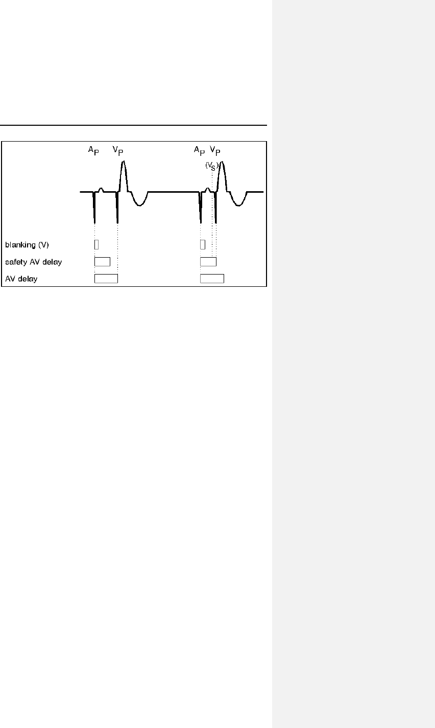
Evia Technical Manual 73
Figure 12. Ventricular blanking time and safety AV delay
(Dual chamber)
7.5.8 Upper Rate and UTR Response
The upper rate is programmable (up to 200 ppm) for the dual
chamber sensing modes [DDD-CLS, DDD(R), VDD(R)], and for
all triggered modes (single and dual chamber). The ventricular
pacing rate will never exceed the programmed upper rate
regardless of the patient's atrial rate.
7.6 Lead Polarity
The programmed lead polarity determines whether the pulse
generator senses or paces in a unipolar or bipolar configuration.
Lead polarity can be programmed separately for sensing and
pacing in both chambers.
If a bipolar lead is connected to the pulse generator, unipolar or
bipolar configuration can be programmed for pacing and
sensing. As compared to bipolar pacing, the unipolar pacing
pulse has the advantage of being clearly identifiable on the ECG.
Unipolar pacing occasionally results in muscle stimulation in the
pulse generator pocket or diaphragm.

74 Evia Technical Manual
Bipolar sensing offers an improved "signal-to-noise" ratio due to
the decreased susceptibility to interference signals like skeletal
myopotentials or EMI, and, therefore, permits programming of
higher sensitivities (lower values).
WARNING
Unipolar/Bipolar – All Evia models can be used with either
unipolar or bipolar IS-1 leads.
7.7 Parameters for Rate-Adaptive
Pacing
The Evia pulse generator achieves rate adaption through
programming of either standard motion-based pacing via a
capacitive accelerometer or by the means of the principle of
closed loop stimulation (CLS) which involves the translation of
myocardial contractility into patient-specific pacing rates.
For standard motion-based rate adaption, the pulse generator is
equipped with an accelerometer located on the hybrid circuit of
the pulse generator. This sensor produces an electric signal
during physical activity of the patient. If a rate-adaptive mode is
programmed, then the sensor signal controls the stimulation
rate. Sensing and inhibition remains in effect during sensor
controlled operation. In the case of high pacing rates, however,
the refractory periods may cover a majority of the lower rate
interval, resulting in asynchronous operation.
When in CLS mode, the pulse generator monitors and
processes the intracardiac impedance signal associated with
myocardial contraction dynamics. Changes in the waveform of
this impedance signal are associated with changes in the
contraction dynamics of the patient’s heart due to the heart’s
inotropic response to exercise. By monitoring these changes,
the pulse generator can provide a pacing rate that is appropriate
and specific to the patient’s physiologic demands.
For a complete list of rate-adaptive pacing modes available in
the Evia, see Section 15.1.
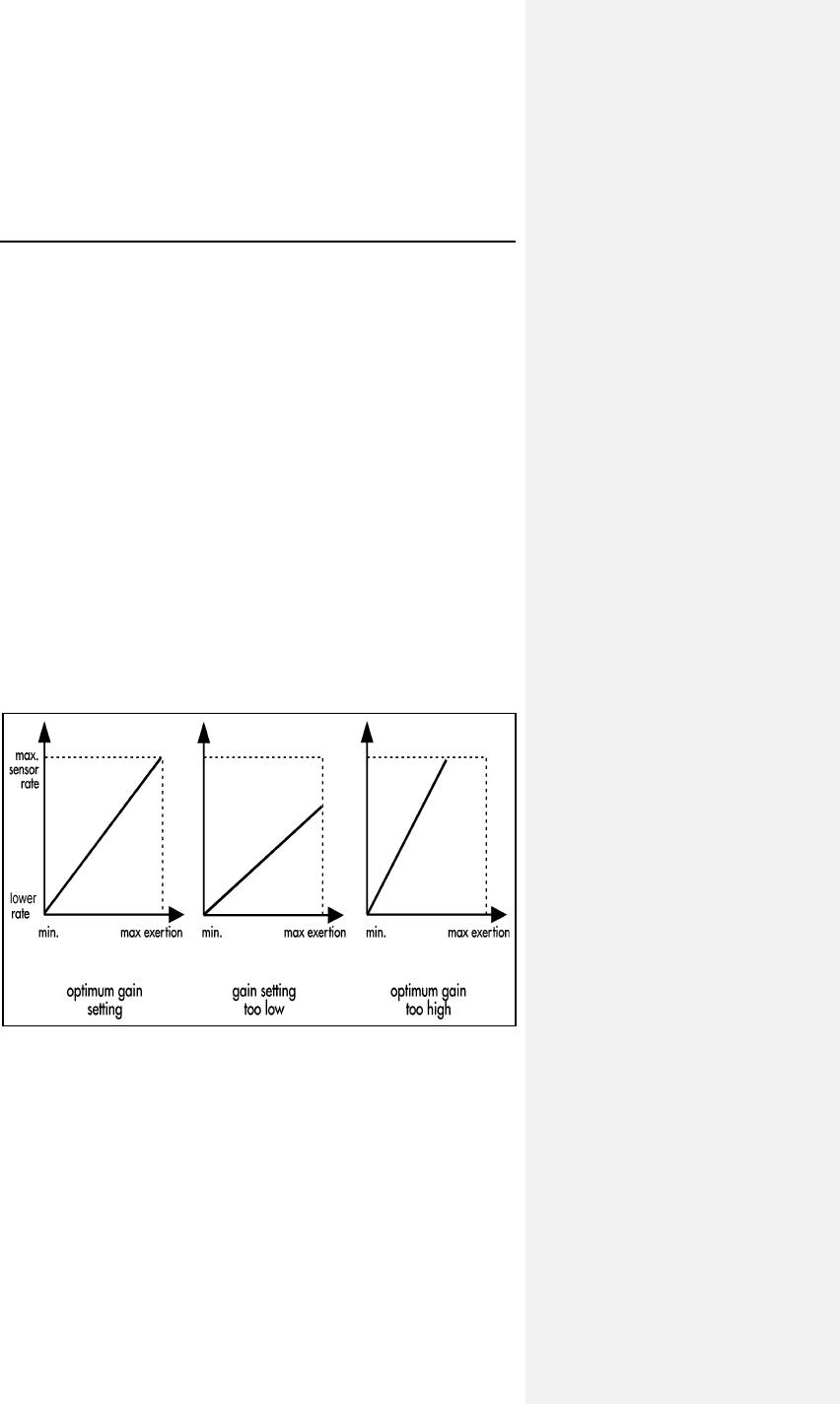
Evia Technical Manual 75
The following functions are available for tailoring the motion
based rate adaptation to the individual patient except for the
maximum closed loop rate, which is relevant to CLS.
7.7.1 Sensor Gain
The sensor gain defines the slope of the linear function between
exertion and pacing rate. It designates a factor by which the
electric signal of the sensor is amplified prior to the signal
processing stages. The programmable amplification permits
adaptation of the individually programmed sensor gain to the
desired rate response. The optimum setting is achieved when
the desired maximum pacing rate during exertion is reached
during maximum exercise levels. The rate increase, rate
decrease and maximum sensor rate settings must be checked
for their suitability with respect to the individual patient before
adjusting the sensor gain.
If the sensor-driven rate is not sufficient at high levels of exertion
the sensor gain setting should be increased. The sensor gain
should be reduced if high pacing rates are obtained at low levels
of exertion.
Figure 13. Influence of sensor gain on the rate response.

76 Evia Technical Manual
7.7.2 Automatic Sensor Gain
Evia pulse generators offer an Automatic Sensor Gain setting,
which allows the physician to have the Sensor Gain parameter
adjusted automatically.
When the Automatic Sensor Gain is activated, the pulse
generator samples the sensor-indicated rate (Figure 14). The
sensor gain will be increased by 10%, if the activity rate does not
reach or exceed the programmed activity rate (fixed to 90% of
maximum sensor rate) for 30 minutes each day over
7 consecutive days. An increase in gain cannot occur more
often than every 7 days. If, during the 24 hour period beginning
at midnight, the activity rate reaches or exceeds the
programmed activity rate (90% of maximum sensor rate) for one
hour, the sensor gain setting is reduced by 10%. A change in the
sensor gain only occurs at midnight.
NOTE:
If the reed switch is closed, the accumulated time at
maximum sensor rate is reset to zero, and the sensor
indicated rate measurement resumes for the period that
remains in that day.
The Automatic Sensor Gain function is primarily influenced
by the Maximum Sensor Rate setting. Therefore the
Maximum Sensor Rate must be appropriately selected.
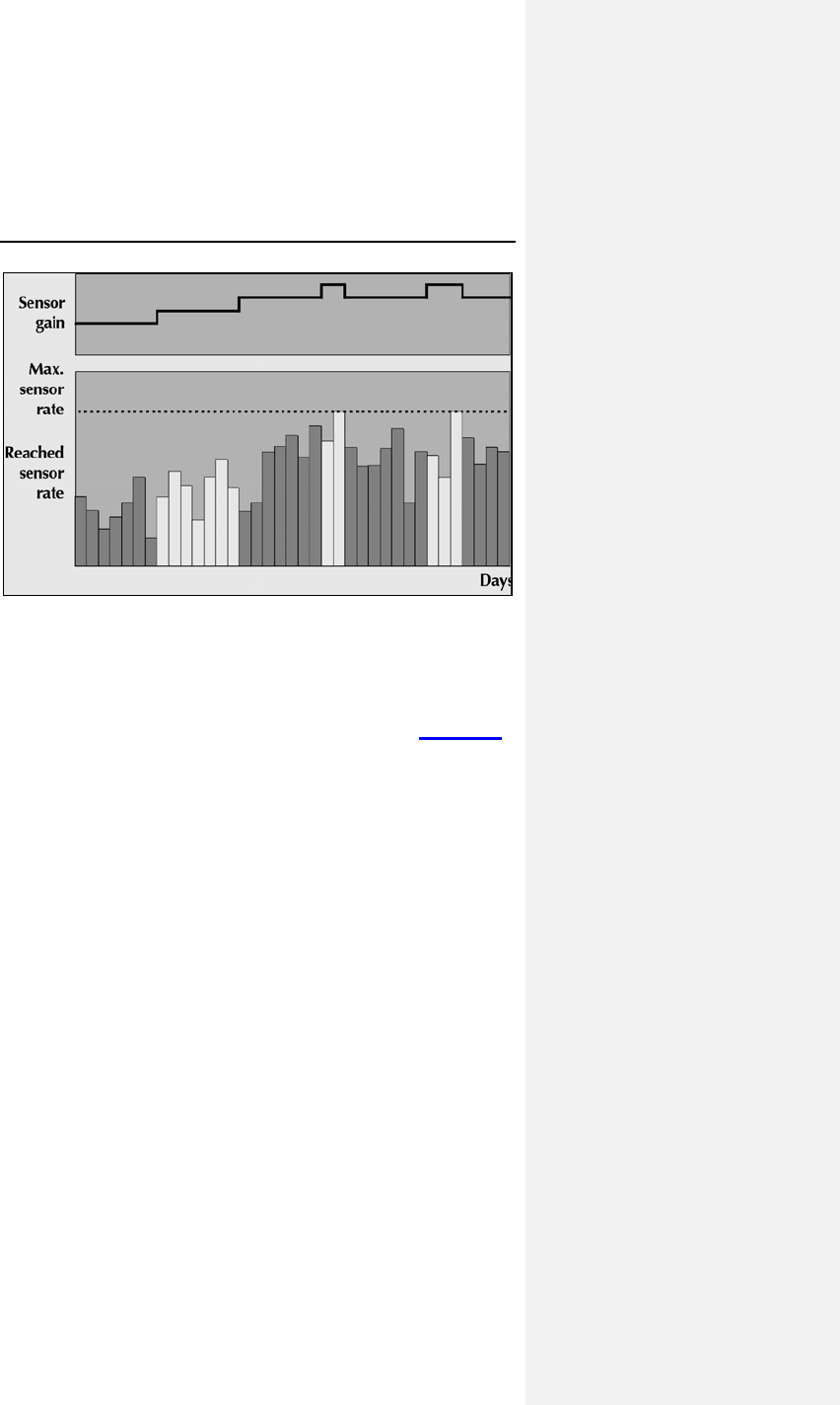
Evia Technical Manual 77
Figure 14. Automatic Sensor Gain
7.7.3 Sensor Threshold
The effects of rate adaptation are limited to sensor signals
exceeding the programmable sensor threshold. Sensor signals
below this threshold do not affect rate response (Figure 15).
The programmable sensor threshold ensures that a stable rate
at rest can be achieved by ignoring sensor signals of low
amplitude that are not related to exertion.
If the pacing rate at rest is unstable, or tends to stay above the
lower rate without activity, the sensor threshold should be
increased. The sensor threshold should be reduced if a
sufficient rate increase is not observed at a given level of
exertion.
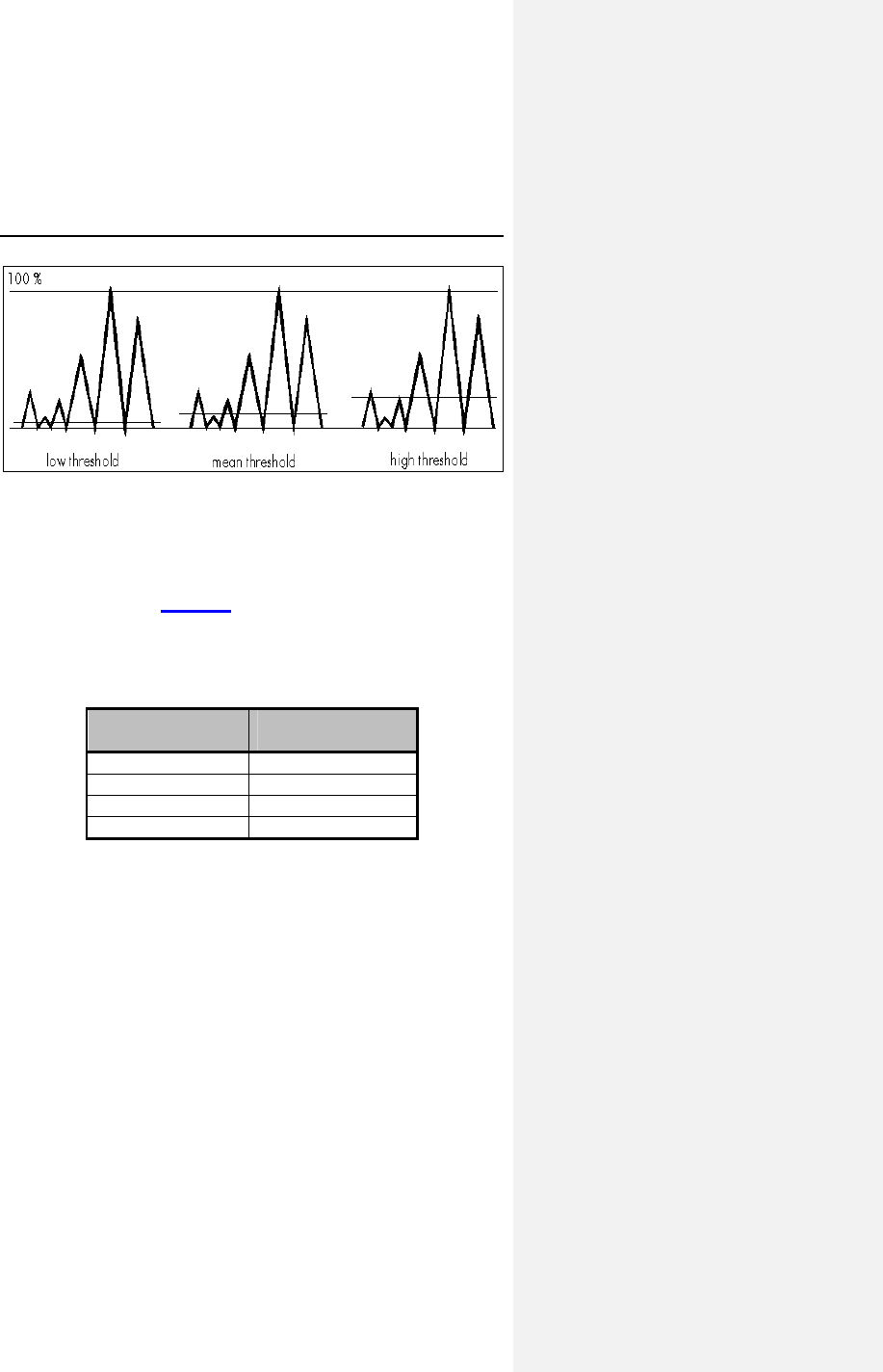
78 Evia Technical Manual
Figure 15. Effect of sensor threshold
7.7.4 Rate Increase
The rate increase parameter determines the maximum rate of
change in the pacing rate if the sensor signal indicates
increasing exertion (Table 18). In DDDR, VDDR, DOOR, VVIR,
VOOR, AAIR and AOOR, a rate increase setting of 2 ppm per
second increase in pacing rate would take 45 seconds to change
from a pacing rate of 60 ppm to 150 ppm.
Table 18: Rate Increase
Increase in
Rate (ppm/s) Time to Increase
Rate (seconds)
1 90
2 45
4 23
10 9
In DDIR and DVIR, the rate increase is slightly slower than
indicated here (depending on the programmed AV interval). The
programmed rate increase setting applies only to the increase in
pacing rate during sensor-driven operation and does not affect
the pacing rate during atrial triggered ventricular pacing.

Evia Technical Manual 79
7.7.5 Maximum Sensor Rate
Regardless of the sensor signal strength, the pacing rate during
sensor-driven operation will never exceed the programmed
maximum sensor rate. The maximum sensor rate only limits the
pacing rate during sensor-driven operation and is independent of
the rate limit. The maximum sensor rate (programmable up to
160 ppm) must be less than or equal to the programmed UTR.
CAUTION
Programming Modifications – Extreme programming
changes should only be made after careful clinical
assessment. Clinical judgment should be used when
programming permanent pacing rates below 40 ppm or above
100 ppm.
NOTE:
In the DDIR and DVIR modes, the sensor rates control the
ventricular pacing rates independent of the AV Delay.
7.7.6 Maximum Closed Loop Rate
With the Evia pulse generator programmed to CLS rate
adaptation, the pacing rate during CLS-driven operation will
never exceed the programmed maximum closed loop rate. The
maximum closed loop rate only limits the pacing rate during
sensor-driven operation and is independent of the rate limit. The
maximum closed loop (programmable up to 160 ppm) must be
less than or equal to the programmed UTR.
80 Evia Technical Manual
CAUTION
Programming Modifications – Extreme programming
changes should only be made after careful clinical
assessment. Clinical judgment should be used when
programming permanent pacing rates below 40 ppm or above
100 ppm.
7.7.7 Rate Decrease
The rate decrease parameter determines the maximum rate of
change in the pacing rate, if the sensor signal indicates
decreasing exertion. In DDDR, VDDR, DOOR, VVIR, VOOR,
AAIR, and AOOR, the rate decrease setting of 0.5 ppm per
second decrease in pacing rate would take 180 seconds to
change from 150 ppm to 60 ppm.
Table 19: Rate Decrease
Decrease in
Rate (ppm/s) Time to Decrease
Rate (seconds)
0.1 900
0.2 450
0.5 180
1.0 90
The programmed rate decrease setting applies only to the
decrease in pacing rate during sensor-driven operation in the
primary chamber being paced.

Evia Technical Manual 81
7.8 Management of Specific Scenarios
7.8.1 2:1 Lock-In Management
2:1 Lock-In Management is an expansion to the Mode Switch
feature. If the AV delay and far-field protection intervals are
programmed such that every second intrinsic atrial event falls
within the blanking period and the pulse generator detects an
atrial rate that is half of the actual rate, the pulse generator does
not Mode Switch during an atrial tachycardia as programmed.
With 2:1 Lock-In Management, the tachycardia is detected and
confirmed, thereby triggering a Mode Switch.
The 2:1 Lock-In Management feature consists of suspicion,
confirmation and termination phases, which are described
below:
Suspicion
The pulse generator suspects 2:1 Lock-In when the following
criteria are met:
• 8 successive V-pace – A-sense (VpAs) sequences have
occurred with an average length shorter than the 2:1
Lock-In VA Length Criterion. This VA Length Criterion is
based on the AV delay (AsVp) and far-field protection
intervals (FFB).
• The mean deviation of these 8 VpAs intervals is less
than the 2:1 Lock-In Stability Criterion, defined as 50ms.
Confirmation
When the suspicion criteria have been met, the AV delay is
increased by the programmed far-field protection interval (up to a
maximum of 300 ms. If an atrial event is detected within the AV
delay and the detected atrial rate is less than the programmed
Mode Switch Detection rate, a 2:1 Lock-In is confirmed.
Otherwise, 2:1 Lock-In is not confirmed, and the AV delay is
gradually decreased to the programmed value. The 2:1 Lock-In
Management feature is suspended for 120 seconds.

82 Evia Technical Manual
Termination
The pulse generator will immediately mode switch to a non-atrial
tracking mode (e.g., DDDR to DDIR) when the confirmation
criteria have been met, and then the 2:1 Lock-In Management
feature is suspended until the pulse generator mode switches
back to the programmed pacing mode.
In order to optimize the programmability of the 2:1 Lock-In
Management feature, the far field protection period is
programmable to allow the physician to ensure that the
protection period is sufficient to recognize cases where a 2:1
lock-in is likely to occur. Refer to Section 7.5.5 for
recommendations for programming the far field protection period
in conjunction with the 2:1 Lock-In Management feature.
7.9 Atrial Upper Rate
The atrial upper rate (AUR) prevents atrial pacing from occurring
in the vulnerable phase after an atrial sensed event during the
PMT protection interval, and ensures that the next atrial paced
event occurs after the heart’s natural atrial refractory period.
To avoid this, an atrial upper rate of 240 ppm (atrial upper
interval (AUI), 250 ms) is started after a PMT-As.
The next Ap can only be emitted after the expiration of the AUI.
When there are high sensor rates, the atrial pacing is shifted.
NOTE:
Right atrial pacing does not occur when mode switching is
activated, and when the atrial upper rate is activated in DDI
mode at the end of the sensor or basic interval.

Evia Technical Manual 83
7.10 Atrial Overdrive Pacing (Overdrive
Mode)
The atrial pacing rate increases after each atrial sensed event
that is not classified as an atrial extrasystole, in an attempt to
suppress atrial tachyarrhythmias. The overdrive algorithm
triggers atrial overdrive pacing and guarantees that pacing
occurs at a rate slightly above the intrinsic sinus rate. Atrial
overdrive pacing thereby minimizes the number of atrial sensed
events. The overdrive mode is available in DDD(R).
The features of Atrial Overdrive pacing include:
After every atrial sensed event (non-AES), the pacing rate is
increased by a fixed rate increase (8 ppm) above the last P-P
interval. If the intrinsic rate does not continue to rise after the
programmable number of cycles (overdrive pacing plateau), the
overdrive pacing rate is reduced in steps of 1 ppm. In each
instance, the rate drop occurs after a fixed 20 cycles has been
completed.
The pacing rate is reduced until an atrial event is again sensed.
Afterwards, the overdrive pacing cycle begins again at an
increased rate.
Protection Function of the Algorithm
Atrial overdrive pacing (Overdrive Mode) consists of different
functions that become effective at high atrial rates:
• When the maximum activity rate (MAR, standard setting
120 ppm, (90… (5)…160 ppm) is exceeded as with atrial
tachycardias, the algorithm is automatically deactivated.
If the rate falls below the MAR, the overdrive algorithm is
reactivated.

84 Evia Technical Manual
• The function is deactivated when the mean of the atrial
rate over a period of twelve hours exceeds the average
safety rate (“overdrive average rate limit = OAR”). The
average safety rate is determined indirectly from the
maximum overdrive pacing rate (MOR minus 10ppm). If
the average safety rate is exceeded, the pacing rate is
incrementally reduced to the basic rate. If the average
atrial heart rate falls below the average safety rate, the
preventive overdrive pacing is reactivated
(activation/deactivation only in a 12 hour rhythm).
• If the function is deactivated for a third time because the
average safety rate has been exceeded, overdrive
pacing remains OFF permanently. The overdrive mode
can not be reactivated until after the pacemaker has
been programmed.
CAUTION
Overdrive Pacing Mode - When programming the overdrive
pacing mode, check whether the selected program can cause
PMT, and whether atrial over drive pacing would result.
Corresponding to the measured retrograde conduction time,
the PMT protection interval must be programmed to a correct
value.
7.11 Management of Specific Scenarios
7.11.1 PMT Management
A PMT is defined as a tachycardia caused by inadvertently
tracking retrograde P-waves. The PMT management feature
includes PMT Protection/Termination and a programmable PMT
detection and termination algorithm.

Evia Technical Manual 85
7.11.2 PMT Protection
Pacemaker-mediated tachycardia (PMT) is normally triggered by
ventricular depolarizations that are not synchronized with atrial
depolarizations (e.g., VES). The tachycardia is maintained in a
retrograde direction by intrinsic VA conduction of the stimulated
ventricular depolarization and in an antegrade direction by
ventricular pacing of the pacemaker that is triggered by P-waves.
It is the objective of the atrial PMT protection interval to not use
retrogradely conducted atrial sensed events for pacemaker
timing, but only to statistically evaluate them for detection of
atrial tachycardia incidents.
To prevent occurrence of a PMT, Evia pacemakers start an atrial
PMT protection interval after each ventricular paced event. If an
atrial event is sensed within this PMT protection interval, this will
neither start an AV delay nor a basic interval.
The length of the PMT protection can be set to automatic (Auto).
In this case, the PMT protection window can be automatically
extended after the PMT is detected and terminated.
NOTE:
The initial values of the PMT protection interval in the
automatic setting at 250 ms after a Vp, and 400 ms after
PVC.
7.11.2.1 PMT Detection and Termination
In addition to PMT prevention, Evia contains a programmable
PMT detection and termination algorithm. The termination
feature will take action in case the prevention was not effective
and a PMT is detected. The PMT detection constantly monitors
for the presence of a PMT.
The Evia PMT detection/termination algorithm consists of
suspicion, confirmation and termination components and is
described as follows.

86 Evia Technical Manual
Suspicion
A PMT is suspected when two criteria are met:
• 8 successive V pace-A sense (Vp-As) sequences have
occurred with a length shorter than the VA criterion.
This VA criterion is programmable between 250 and 500
ms.
• The mean deviation of these 8 Vp-As intervals is less
than the Stability criterion parameter, defined as less
than 25 ms.
Confirmation
When the suspicion criterion has been met, the Evia slightly
modifies the AV delay interval (+ or - 50 ms) or the upper
tracking rate (+50ms) for one cardiac cycle. If the Vp-As interval
remains stable, a PMT is confirmed. Otherwise, a PMT is not
confirmed and the algorithm restarts. Once the PMT algorithm
has confirmed a PMT, the cycle is broken as follows:
Termination
Evia extends PVARP (Post Ventricular Atrial Refractory Period)
to the VA interval + 50 ms
7.12 Adjustment of the PMT Protection
Window
The PMT protection window can be automatically adjusted. This
automatic adjustment functions in the following manner:
When the PMT is detected and terminated, the PMT protection
interval is extended by 50 ms. If no additional PMTs arise within
seven days, the length of the PMT protection interval is reduced
by 50 ms. The initial values of the PMT protection interval in the
automatic setting at 250 ms after Vp and 400 ms after a PVC.
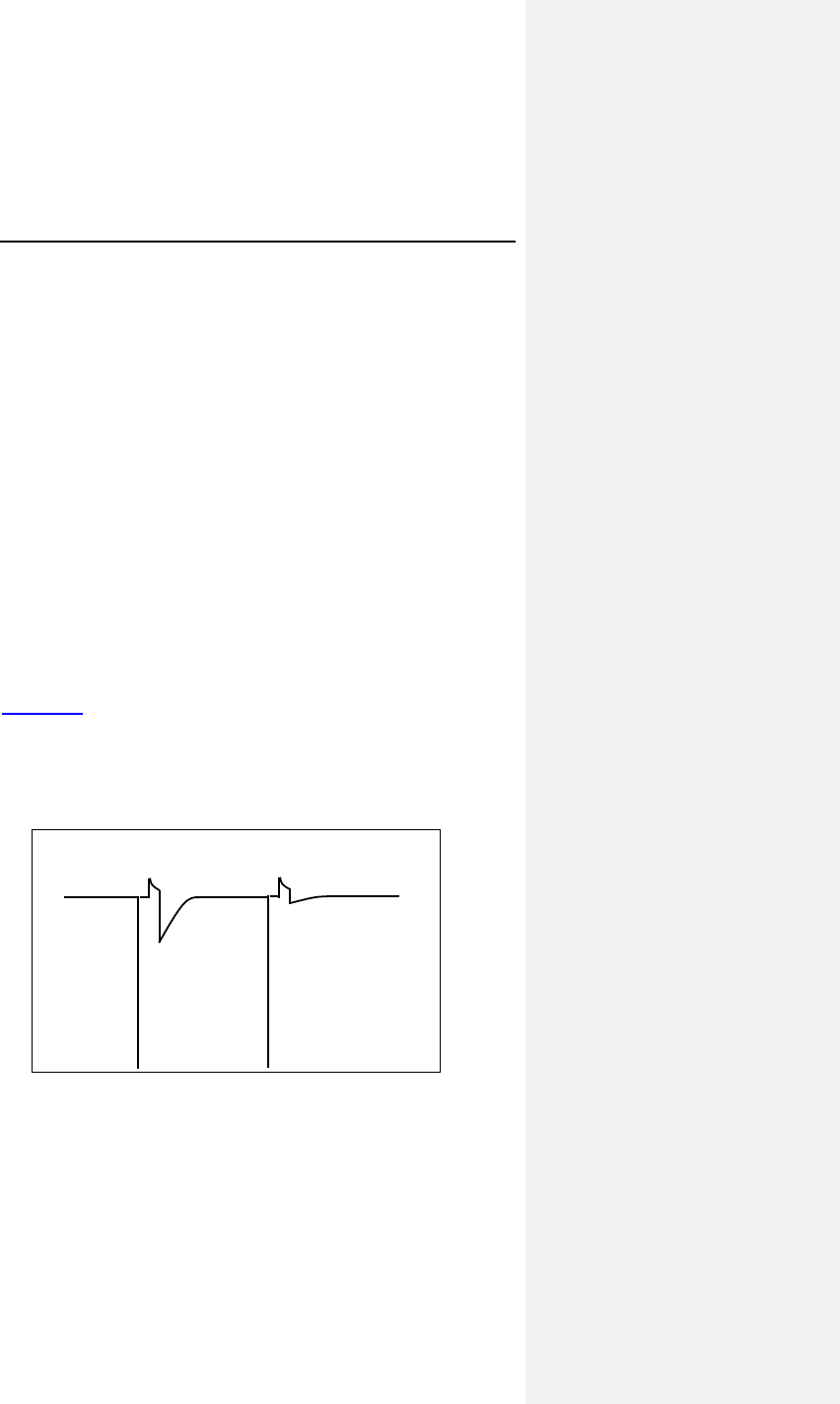
Evia Technical Manual 87
7.13 Ventricular Capture Control (VCC)
7.13.1 Feature Description
The VCC feature periodically measures the capture threshold,
and automatically adjusts the pacing output (with a
programmable safety margin). Additionally, the feature
continuously assesses ventricular pacing capture on a beat-to-
beat basis and responds to any loss of capture with a safety
back-up pulse. During the clinical evaluation of the Ventricular
Capture Control algorithm, it was demonstrated that use of
Ventricular Capture Control can increase device longevity (as
compared to standard programming).
Differences in the signal morphology between the polarization
artifact and the evoked response signal are used to distinguish
capture events from non-capture events. The polarization
artifact is the signal caused by the pacing pulse between the
pacing electrode and the cardiac tissue. The evoked response
signal is the intracardiac signal measured during electrical
activation of the myocardium.
Figure 16 shows an example of an evoked response signal and
a polarization artifact. After an effective blanking period of
20 ms, the signal is evaluated over the next 60 ms. Several
characteristics of the signal falling into this window are evaluated
in order to discriminate the evoked response (capture) from
polarization artifact (possible non-capture).
Figure 16. Example of a Capture and a Non-Capture beat
Evoked Response
Polarization Artifact
Captur Non-Capture

88 Evia Technical Manual
Table 20 contains a list and description of the acronyms and
terms pertaining to the VCC feature used in this manual.
Table 20: Acronyms and Terms
Term Definition
CV Capture Verification - A component of the
VCC feature that provides beat-to-beat
classification of capture and non-capture.
ATM Automatic Threshold Measurement - A
component of the VCC feature that
periodically measures the ventricular pacing
threshold. ATM can only occur after a
successful CV.
Evoked
Response
The intracardiac signal measured during
electrical activation of the cardiac tissue.
LOC Loss-of-Capture – The VCC feature classifies
loss of capture when a series of ventricular
pacing pulses at varying AV delays did not
capture (with a maximum of 3 consecutive
NC’s).
MaxVCCAmp Threshold test start – This programmable
parameter is the maximum voltage setting
that VCC will set after a successful CV.
NC Non-Capture – The VCC feature identifies a
non-capture as a single ventricular pacing
pulse without capture.
Polarization
Artifact
The signal or noise caused by the pacing
pulse between the pacing electrode and the
cardiac tissue.
Safety Margin The safety margin is the difference between
the pacing threshold and the programmed
pacing amplitude.
SA Signal Analysis - A component of the VCC
feature that periodically determines whether
evoked responses are appropriately detected
and that pacing artifact is sufficiently small in
amplitude. If the SA determines that the
signal is not acceptable, then the other
portions of the VCC feature cannot be
activated.
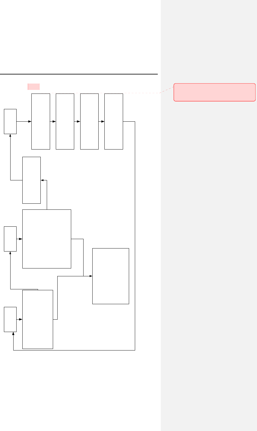
Evia Technical Manual 89
Figure 17. VCC flow chart
SQC CTS CCC
ySets AV delay to 50ms
yFive paces at MaxACCAmp
yFive "double paces" to
evaluate polarization
Pass
Fail
yAV delay remains 50ms
yStarting from MaxACCAmp,
stepwise reduction of the
output every 2 cycles until
threshold is found with a
0.1V resolution
yBack-up pulse is emited if
NC occurs (pulse width set to
1ms)
ySet Amp = MaxACCAmp or
higher
yRepeat SQC/CTS at next
scheduled time
yThree consecutive double
failures of SQC/CTS will
disable ACC
Set Amp = Threshold +
Safety Margin
Fail
Pass
Beat-to-beat monitoring for
non-capture
Back-up pulse is emitted if
NC occurs (pulse width set
to 1ms)
If LOC is confirmed, set Amp
= MaxACCAmp and perform
SQC/CTS
Fusion avoidance scheme
(AVD lengthening and
shortening)
Kommentar [MJ1]: Currently Grace
is working on re-creating and updating
this figure.

90 Evia Technical Manual
The feature includes three primary components: Signal Analysis,
Capture Threshold Search, and Capture Verification. The
following paragraphs describe the operation of these three
components (SA, ATM, and CV) of VCC while active in DDD(R)
pacing mode. In the other modes (VDD(R) and VVI(R)), there
are slight variations in the operation of VCC. Figure 17 provides
a flow chart of the VCC operation.
Signal Analysis (SA)
A polarization artifact that is too large may disturb the cardiac
signal following the pacing pulse and result in misclassification of
the event. Conversely, the evoked response signal may be too
small or may not meet the capture criteria, which again may lead
to misclassification of the event. Therefore, the SA analyzes the
evoked response and the amplitude of the polarization artifact.
A successful SA must always be completed before the Capture
Threshold Search or the activation of Capture Verification.

Evia Technical Manual 91
1. SA is performed in two separate phases. In both
phases, the AV delay is shortened to 50 ms after a
paced atrial event and to 15 ms after a sensed atrial
event to ensure ventricular pacing. First, five ventricular
pacing pulses are delivered at MaxVCCAmp, which is
the programmable maximum voltage setting (2.4, 3.0,
3.6, 4.2, 4.8V). If non-capture is detected at the
maximum voltage setting, the second phase of the SA is
aborted and the test is classified as unsuccessful. In the
next phase, five “double” pacing pulses (one pacing
pulse followed by another pacing pulse 100 ms later, in
the absolute refractory period) are delivered. These
pulses are used to verify that the polarization artifact is
small enough to distinguish capture from non-capture. If
the artifact following the second pacing pulse is higher
than a certain limit, then SA is classified as
unsuccessful. If necessary, this test can be repeated at
a lower maximum voltage setting.
2. If the first SA after activating VCC is not completed
successfully, VCC is immediately disabled, and the
pacing amplitude is programmed to MaxVCCAmp. VCC
then requires manual reactivation of the feature with the
programmer.
3. If the first SA after activating VCC is completed
successfully, but subsequent SA’s are not completed
successfully, then VCC is suspended, and the pacing
amplitude is programmed to the last measured threshold
plus the safety margin. The SA will be attempted up to
three times. After the 3rd failure, VCC is disabled, and
the pacing amplitude is programmed to the
MaxVCCAmp plus the Safety Margin of 1.2V. VCC then
requires manual reactivation of the feature with the
programmer.

92 Evia Technical Manual
Automatic Threshold Measurement (ATM)
1. The ATM is the component of the VCC feature that
measures the ventricular pacing threshold by stepping
down the output until non-capture occurs.
2. The ATM occurs over a series of cardiac cycles and
begins at the threshold test start that decreases until
capture is lost. AV delay is shortened to 50 ms after a
paced atrial event and to 15 ms after a sensed atrial
4event to ensure ventricular pacing.
3. The pacing amplitude decrements with every paced beat
by 0.6V, until the first non-captured beat. The algorithm
then decrements by smaller increments of 0.1V until the
first failed capture, at which point it determines that the
capture threshold is preceding value. .
4. If two out of three non-capture events are detected, the
pacing amplitude is set to the sum of the pacing
threshold voltage and the programmed safety margin. If
two non-captures are detected when the voltage
decrements are greater than 0.1 V, the pacing amplitude
is set to the previous amplitude and then the amplitude
decrements by 0.1 V until the pacing threshold is
determined. When another two non-capture are
detected, the previous voltage setting is the pacing
threshold.
5. The pacing amplitude is then set to the pacing threshold
plus a programmable safety margin (0.5 V through 1.2 V
in steps of 0.1 V).
6. In addition to performing the threshold search after a
loss of capture, the search is also conducted at a
programmable interval or a specific time during the day
to provide an accurate safety margin even with gradual
changes in the pacing threshold. Note that a CV
initiated by spontaneous loss of capture will reset the
timer that triggers the next periodic measurement if the
search is programmed to interval.
Capture Verification (CV)
The Capture Verification function is the component of the VCC
feature that provides beat-to-beat capture verification. (Not
available in the ATM mode).

Evia Technical Manual 93
1. If VCC determines that capture has been maintained,
then the pulse amplitude remains at that current setting
and no action is required.
2. If VCC determines that non-capture (NC) occurred, then
a safety back-up pacing pulse is delivered at an
increased energy (same output voltage and pulse width
extended to 1.0 ms) within 130 ms after the non-
captured pacing pulse.
3. If a series of ventricular pacing pulses at varying AV
delays result in loss-of-capture, a Signal Analysis (SA)
and Automatic Threshold Search (ATM) are initiated to
determine the current pacing threshold.
4. The algorithm is designed to respond appropriately to
fusion beats. In order to discriminate non-capture from
fusion, a capture confirmation algorithm varies the AV
delay after detection of non-capture in the dual chamber
pacing modes. First, fusion is diminished by extending
the AV delay. If a second non-capture is detected, the
AV delay is returned to the programmed AV delay. If a
third consecutive non-capture is detected, loss of
capture is confirmed and a Signal Analysis and
Automatic Threshold Search are initiated. If the first
event was truly fusion, the extended AV delay could
allow intrinsic conduction. The AV delay will not return
to the normal programmed value until ventricular pacing
is required. In case the capture confirmation continues
to detect non-captures without detecting 3 consecutive
non-captures, the algorithm shortens the AV delay
(50 ms after an atrial paced event and 15 ms after an
atrial sensed event for up to 2 paced cycles) to confirm
the occurrence of non-capture. When VCC and CLS are
both enabled, the AV delay is extended after detection of
non-capture and then capture confirmation is temporarily
disabled while CLS performs an AV Hysteresis Scan.

94 Evia Technical Manual
7.13.1.1 Algorithm Suspension, Abort and Disabling
The VCC feature is inactive until the first SA and CV after
programming is completed successfully. The SA/CV sequence
is unsuccessful when the SA or CV fail or are aborted. In
addition, an SA/CV sequence can be postponed and CV can be
temporarily suspended.
The SA/CV sequence will fail when the following events occur:
• Non-capture during SA: non-capture occurs twice in the
second through fifth cycles of the SA (at the maximum
voltage amplitude setting).
• High polarization artifact during SA: the polarization
artifact measured during the SA is too high.
• No non-capture during CV: the threshold search
decreases the output to 0.1 V without detecting non-
capture.
An ongoing SA/CV sequence will abort when the following
events occur:
• Mode Switch: Mode switch has a higher priority than the
SA/CV. If Mode switch aborts an SA/CV, the device will
be set to high output. After reversion back to the
programmed mode, a new SA/CV will be initiated.
• Programmer Wand application: An ongoing SA/CV
aborts when a magnet (programmer wand) is applied
and the device is then set to high output. After removal
of the magnet, a new SA/CV is started.
• Search timer expiration (120 seconds): if the SA/CV
takes longer than 120 seconds to be completed (e.g.
due to sensing), the SA/CV will be aborted and the
device will be set to high output.
• Noise detection: if excessive noise is detected, the initial
SA/CV will be aborted and the device will be set to high
output.

Evia Technical Manual 95
A SA/CV sequence will be postponed when the following events
occur:
• Mode switch is ongoing: If Mode switch is ongoing when
an SA/CV is scheduled, the SA/CV will be postponed
until reversion back to the programmed mode.
• The presence of a magnet is detected: A scheduled
SA/CV is postponed when a magnet (programmer wand)
is detected. After removal of the magnet, the SA/CV is
started.
• The ventricular rate is higher than 110 bpm: A scheduled
SA/CV is postponed when the ventricular rate is higher
than 100 bpm. When the ventricular rate drops below
100 bpm, the SA/CV is started.
The continuous capture control (CV) will be suspended and the
ventricular pacing amplitude is set to high output when the
following events occur:
• The ventricular rate is higher than 110 bpm: CV is
suspended while the ventricular rate is higher than
110 bpm. When the ventricular rate drops below
110 bpm, CV is resumed.
• Mode Switch: CV is suspended and the device is set to
high output until reversion back to the programmed
mode.
The VCC feature will be automatically turned OFF when the
following events occur:
• The initial SA/CV sequence after activating VCC failed
• Three subsequent and consecutive failed SA attempts
• The occurrence of 25 Losses of Capture between two
consecutive days
• ERI: the device will be set to ERI mode with VCC OFF
• Unipolar lead failure is detected
The occurrence of these unsuccessful, aborted or postponed
SA/CV sequences and disabling of the VCC feature are reported
in the Status log in the VCC statistics.

96 Evia Technical Manual
7.13.2 Ventricular Capture Control
Programming
VCC is programmable to ON, Active Threshold Monitoring (ATM)
modes, and OFF. Table 21 provides details about the VCC
programmability.
Table 21: VCC Programmability
Programmable Modes for
V
CC
V
CC Components ON
A
TM
Pulse width
programmability
less than or equal to 0.4 ms
SA and Capture
Threshold searches
Yes Yes
Set output to
threshold + safety
margin
Yes No
Capture Verification
(CV)
Yes No
When programmed to ON, the device will continuously monitor
the cardiac signal following the pacing pulse to verify that a
depolarization occurred as a result of the pulse. Upon detection
of non-capture, the device will issue a back-up pulse at a higher
output (pulse width increased to 1ms) within 130 ms. If loss-of-
capture (LOC) occurs, the device will initiate an SA/CV.
Additionally, the device will perform regular threshold searches
at the programmed time each day. After a successful threshold
search, the device will program the pulse amplitude to the
threshold plus the programmed Safety Margin. The device will
never set the amplitude lower than the fixed minimum VCC
Amplitude (Min Ampl.) of 0.7V.
NOTE:
After programming the Ventricular Capture Control feature to
ON or ATM, the device will perform a Signal Analysis and a
capture threshold search. This sequence can take up to
2 minutes.

Evia Technical Manual 97
7.14 Program Consult®
Program Consult® provides clinicians with the option to increase
programming efficiency by providing programming suggestions
for frequent pacemaker patient conditions and having the
capability to store individual programming for future usage (can
store up to three individual parameter sets for future
programming).
Program Consult is not an algorithm but uses preset settings
based on the recommendations of the ACC/AHA/HRS guidelines
for device based therapy1. Program Consult only shows
recommendations for specific parameter settings to the user and
clearly highlights them as modifications to the active permanent
program prior to making any changes to device programming.
This feature is part of the ICS parameter section and is located
on the main Evia / Entovis programmer screen under the
selection Program Sets. Upon selection of Program Consult, a
sub-window opens with multiple selections depending on the
underlying disease. Upon selection of a particular option, the
parameter page displays the suggested parameter values in
blue color. This indicates the recommended setting changes to
the user (from the current settings) so that they can confirm them
prior to activation. If desired, modifications can be made prior to
transmitting the new program to the pulse generator as an
updated permanent program. The following tables compare the
suggested Program Consult and standard parameters for
different patient conditions:
1 ACC/AHA/HRS 2008 Guidelines for Device-Based Therapy of Cardiac Rhythm
Abnormalities: Executive Summary: A Report of the American College of
Cardiology/American Heart Association Task Force on Practice Guidelines
(Writing Committee to Revise the ACC/AHA/NASPE 2002 Guideline Update for
Implantation of Cardiac Pacemakers and Antiarrhythmia Devices) Developed in
Collaboration With the American Association for Thoracic Surgery and Society of
Thoracic Surgeons
Andrew E. Epstein, John P. DiMarco, Kenneth A. Ellenbogen, N.A. Mark Estes,
III, Roger A. Freedman, Leonard S. Gettes, A. Marc Gillinov, Gabriel Gregoratos,
Stephen C. Hammill, David L. Hayes, Mark A. Hlatky, L. Kristin Newby, Richard
L. Page, Mark H. Schoenfeld, Michael J. Silka, Lynne Warner Stevenson, and
Michael O. Sweeney

98 Evia Technical Manual
Table 22: SSS including Brady-Tachy Syndrome and
SSS with Chronotropic Competence
Standard
Program
SSS
including
Brady-
Tachy
Syndrome
SSS with
Chronotropic
Competence
Valid for: DR(-T) DR(-T) DR(-T)
Parameters
Mode DDD-R DDD-CLS DDD
Rate Hysteresis
(ppm)
OFF --- OFF
CLS Vp required --- No ---
CLS Resting
Rate Control
--- +20 ---
AV Hysteresis OFF IOPT ---
Holter settings
High atrial rate AT ModeSw ModeSw
HVR limit (bpm) 180 160 160
Table 23: Permanent High-Degree AV Block and
Paroxysmal High-Degree AV Block
Standard
Program
Permanent
High-Degree
AV Block
Paroxysmal
High-Degree
AV Block
Valid for: DR(-T) DR(-T) DR(-T)
Parameters
Mode DDD-R DDD DDD
Rate Hysteresis
(ppm)
OFF -10 -10
Rate Hysteresis
Rep. Cycles
--- 5 5
Rate Hysteresis
Scan Cycles
--- 5 5
AV Hysteresis OFF OFF ---
Holter settings
High atrial rate AT OFF OFF
High ven. Rate ON OFF OFF
Pre-trigger
recording (%)
75 --- ---
IEGM signal Filtered --- ---
HAR limit (bpm) 200 --- ---
HVR limit (bpm) 180 --- ---
HVR counter 8 --- ---

Evia Technical Manual 99
Table 24: Bradycardia with Permanent Atrial Fibrillation and
Dual Node Disease + Permanent AV Block
Standard
Program
Bradycardia
with
Permanent
Atrial
Fibrillation
Dual node
Disease +
Permanent
AV Block
Valid for: DR(-T) DR(-T), SR(-T) DR(-T)
Parameters
Mode DDD-R VVI-CLS DDD-CLS
Rate Hysteresis
(ppm)
OFF --- ---
CLS Vp required --- No Yes
CLS Resting
Rate Control
--- +20 +20
AV Hysteresis OFF --- OFF
2:1 Lock-in
Protection
ON --- ON
Mode switch ON --- ON
PMT ON --- ON
Holter settings
High atrial rate AT OFF ModeSw
High ven. Rate ON ON ON
HAR limit (bpm) 200 --- 200
HVR limit (bpm) 180 160 160
HVR counter 8 8 8

100 Evia Technical Manual
Table 25: Dual Node Disease + Paroxysmal AV Block and
Vasovagal Syncope
Standard
Program
Dual Node
Disease +
Paroxysmal
AV Block
Vasovagal
Syncope
Valid for: DR(-T) DR(-T) DR(-T)
Parameters
Mode DDD-R DDD-CLS DDD-CLS
Rate Hysteresis
(ppm)
OFF --- ---
CLS Vp required --- No No
CLS Resting
Rate Control
--- +20 OFF
AV Hysteresis OFF IOPT IOPT
Holter settings
High atrial rate AT ModeSw OFF
High ven. Rate ON ON OFF
Pre-trigger
recording (%)
75 75 ---
IEGM signal Filtered Filtered ---
HAR limit (bpm) 200 200 ---
HVR limit (bpm) 180 160 ---
HVR counter 8 8 ---

Evia Technical Manual 101
Table 26: Symptomatic First-Degree AV Block and
Infrequent Paroxysmal Pauses (< 5%)
Standard
Program
Symptomatic
First-Degree
AV Block
Infrequent
Paroxysmal
Pauses
(< 5%)
Valid for: DR(-T) DR(-T) SR(-T)
Parameters
Mode DDD-R DDD VVI
Rate Hysteresis
(ppm)
OFF OFF -10
Rate Hysteresis
Rep. Cycles
--- --- 5
Rate Hysteresis
Scan Cycles
--- --- 5
AV Hysteresis OFF OFF ---
2:1 Lock-in
Protection
ON ON ---
Mode switch ON ON ---
PMT ON ON ---
Holter settings
High atrial rate AT OFF OFF
High ven. Rate ON OFF OFF
Pre-trigger
recording (%)
75 --- ---
IEGM signal Filtered --- ---
HAR limit (bpm) 200 --- ---
HVR limit (bpm) 180 --- ---
HVR counter 8 --- ---
7.15 Home Monitoring (Evia DR-T)
Home Monitoring enables the exchange of information about a
patient’s cardiac status from the implant to the physician. Home
Monitoring can be used to provide the physician with advance
reports from the implant and can process them into graphical
and tabular format called a Cardio Report. This information
helps the physician optimize the therapy process, as it allows the
patient to be scheduled for additional clinical appointments
between regular follow-up visits if necessary.
The implant’s Home Monitoring function can be used for the
entire operational life of the implant (prior to ERI) or for shorter
periods, such as several weeks or months.

102 Evia Technical Manual
Home Monitoring can be utilized as a functional replacement for
in-office follow-up visits and allows the time between routine,
scheduled, in-office follow-ups of BIOTRONIK implantable
devices to be extended to twelve months or more. Home
Monitoring evaluation of implanted devices and patient status is
as safe as conventional in-office follow-ups. BIOTRONIK’s
Home Monitoring system provides early detection of arrhythmic
events and of silent, asymptomatic events. Automatic early
detection of clinical events by Home Monitoring leads to earlier
intervention than conventional in-office follow-ups and improves
adherence to scheduled follow-ups.
NOTE:
When ERI mode is reached, this status is transmitted.
Further measurements and transmissions of Home
Monitoring data are no longer possible.
7.15.1 Transmission of Information
The implant transmits information with a small transmitter, which
has a range of about 6 feet (2 meters). The patient’s implant
data are sent to the corresponding patient device in configurable
periodic intervals.
The minimal distance between the implant and the patient device
must be 6 inches (15 cm).
7.15.2 Patient Device
The patient device (Figure 18) is designed for use in or away
from the home and is comprised of the mobile unit and the
associated charging station. The patient can carry the mobile
unit during his or her occupational and leisure activities. The
patient device is rechargeable, allowing for an approximate
operational time of 24 hours. It receives information from the
implant and forwards it via the cellular mobile network or the
standard telephone system to a BIOTRONIK Service Center.
For additional information about the patient device, please refer
to its manual.

Evia Technical Manual 103
7.15.3 Transmitting Data
The implant’s information is digitally formatted by the
BIOTRONIK Service Center and processed into a concise report
called a Cardio Report. The Cardio Report, which is adjusted to
the individual needs of the patient, contains current and previous
implant data. The Cardio Report is sent to the attending
physician via fax or is available on the Internet, which is selected
during registration of the patient. For more information on
registering for Home Monitoring, contact your BIOTRONIK sales
representative.
The password protected BIOTRONIK Home Monitoring website
can be accessed at the following URL:
www.biotronik-homemonitoring.com
An online help menu is available in order to assist with the use of
the Home Monitoring website.
Use of the Internet for reviewing Home Monitoring data must be
in conjunction with the system requirements listed in Table 27.
Table 27: System Requirements / Recommendations
System
Requirements System
Recommendations
(for Optimal Usage)
Screen
Resolution
1024 x 768 ≥ 1280 x 1024
Internet
Bandwidth
56 kB/sec ≥ 128 kB/sec
(DSL, cable modem)
PC 800 MHz Pentium
processor,
128 MB RAM
N/A
Internet
Browser
MS Internet
Explorer 5.5
≥ MS Internet
Explorer 5.5
- or -
≥ Mozilla 1.8
(Firefox ≥ 2.0)
Acrobat
Reader
Version 6.1 Version 6.1 or higher
Communication
Channel
Fax (G3) or e-mail Fax (G3), e-mail or
mobile phone
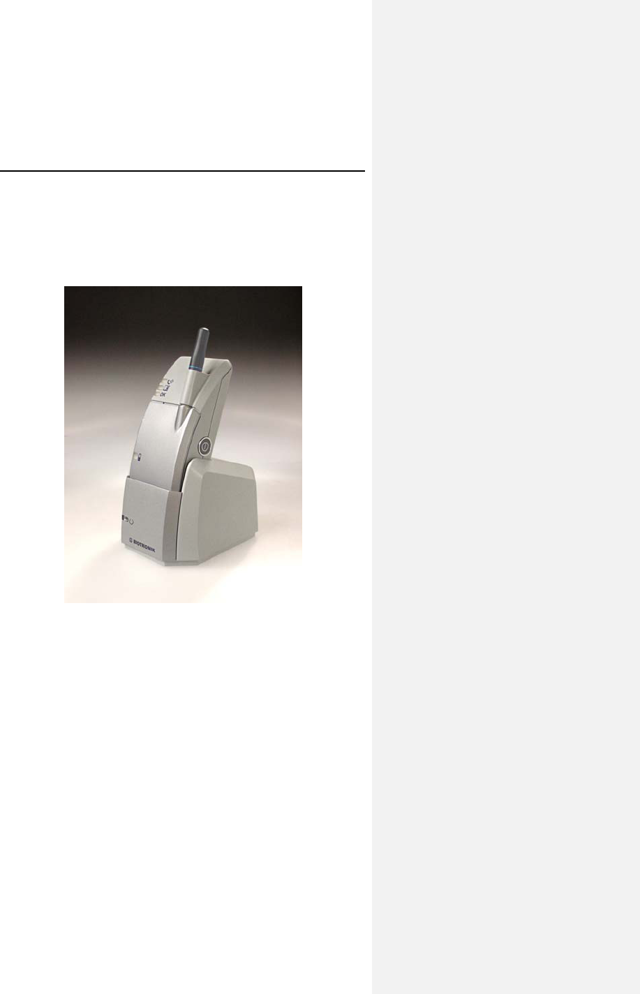
104 Evia Technical Manual
Additionally, the attending physician may register to be informed
of the occurrence of an Event Triggered Message through email
or SMS (i.e., mobile phone) with a brief text message. If
registered for Internet availability, the patient’s detailed implant
data can then be viewed by logging onto the Home Monitoring
website.
Figure 18: Example of Patient Device with Charging Stand

Evia Technical Manual 105
7.15.4 Types of Report Transmissions
When the Home Monitoring function is activated, the
transmission of a report (Cardio Report) from the implant can be
triggered as follows:
• Trend report – the time period (daily) initiates the report
• Event report – the pulse generator detects certain
events, which initiate a report
7.15.4.1 Trend Report
The time of the report transmission is programmable. For
periodic messages, the time can be set anywhere between 0:00
and 23:59 hours. It is recommended to select a time between
0:00 and 4:00.
The length of the time interval (monitoring interval) is preset to
“daily”. For each monitoring interval, a data set is generated in
the implant and the transmission is initiated at the designated
time.
7.15.4.2 Event Report
When certain cardiac and technical events are detected by the
implant, a report transmission is automatically triggered. This is
described as an “event message”.
The following clinical and technical events initiate a Home
Monitoring message transmission:
• Atrial Lead Check < 100+/-50 Ohm and > 2500+/-500
Ohm
• Ventricular Lead Check < 100+/-50 Ohm and > 2500+/-
500
• VCC Disabled
• ERI detected
• High Ventricular rate
• Atrial tachyarrhythmia persisting beyond a
programmable time limit or

106 Evia Technical Manual
• Mode Switch episode persisting beyond a
programmable time limit
NOTE:
The attending physician must notify the BIOTRONIK Service
Center about which of these events he/she wishes to be
informed.
7.15.5 Description of Transmitted Data
The following data are transmitted by the Home Monitoring
system, when activated. In addition to the medical data, the
serial number of the implant is also transmitted.
The Monitoring Interval
The monitoring interval is considered the time period since the
last periodic message was transmitted. In a periodic report, the
monitoring interval since the previous periodic report would be
24 hours.
The following data are transmitted for the Cardio Report by the
Home Monitoring system, when activated. In addition to the
medical data, the serial number of the implant is also
transmitted.
Device Status & Home Monitoring Settings
Containing device and message identifying values that pertain to
the implant and Home Monitoring:
• Implantation Date
• Battery voltage & Date of Measurement
• Device Status
• Current Consumption for ERI calculation (done by the
Service Center)
• Date and time of Last Follow-up and Program Counter
• Message Creation Date/Time
• Device Serial Number
• Current ROM/RAM Version Information

Evia Technical Manual 107
Leads
• Automatic Threshold Monitoring
− Measured RV pacing threshold
− RV enabled/disabled
− Date/time of ATM measurement
• Pacing Impedance (RA, RV)
• Sensing Amplitude (RA, RV)
Pacing Counters (Brady)
• AV-Sequences
− Intrinsic Rhythm (AsVs)
− Conducted Rhythm (AsVp)
− Atrial Paced Rhythm (ApVs)
− Complete Paced Rhythm (ApVp)
Atrial Arrhythmia
• Atrial Tachy Episodes (36 out of 48 criteria)
− Counter on AT/AF detections per day
− Atrial Burden per day°
− Ongoing Atrial Episode Time (programmable for 6,
12 or 18 hrs)
• Mode Switching
− Number of Mode Switches
− Duration of Mode Switches
Ventricular Arrhythmia
• High Ventricular Rate Counters
Transmitted Device Settings
The primary programmed parameters for the following are sent
in the data package:
• Leads – (e.g., Pacing Output, Configuration)
• Brady - (e.g., Basic Rate, UTR, AV-Delays, RV
Sensitivity)

108 Evia Technical Manual
• IOPT - (ON/OFF)
• HM Settings - (e.g., ON/OFF, transmission time (daily),
IEGM transmissions ON/OFF, periodic IEGM, ongoing
atrial episode, statistics, holter)
• Miscellaneous other information
7.15.5.1 IEGM Online HDs
The Evia provides the ability to transmit IEGM Online HD (IEGM
and marker data) from the periodic follow-ups as an addition to
the current messages.
An IEGM with up to 2 channels (RV and/or RA) are sent in one
message, depending on the number of IEGM channels
programmed in the Holter configuration.
The following markers are also transmitted: AS (including Ars), AS
(PMT), AP, VS (including Vrs), VP (atrial and refractory sensed
events included with sensed events).
The Evia includes a programmable parameter to disable or
enable the IEGM transmission.

Evia Technical Manual 109
8. Statistics
8.1 Statistics Overview
Evia pulse generators can store a variety of statistical
information. The various statistics consist of such features as
rate histograms, event counters, sensor trends, VES statistics,
and activity reports, which are described in the following
sections.
8.1.1 Timing
• Event Counters
• Event Episodes
• Rate Trend 24 hours
• Rate Trend 240 days
• Rate Histograms
8.1.2 Atrial Arrhythmia
• Atrial Burden
• Time of Occurrence
• Mode Switching
8.1.3 Sensor
• Sensor Histogram
• Activity Report

110 Evia Technical Manual
8.1.4 Sensing
• P/R -wave Trends
• Far Field Histogram
• As-Vs Interval Distribution Curve
• Ap-Vs Interval Distribution Curve
8.1.5 Ventricular Arrhythmia
• PVC
• Couplets
• Triplets
• Runs 4…8
• Runs > 8
• High Ventricular Rate Episode Count
8.1.6 Pacing
• Lead Impedance Trends
• Pulse amplitude / Threshold Trend
• Pulse Amplitude Histogram
• Capture Control Status”
8.1.7 General Statistical Information
• The Evia pulse generators statistics modes are always
in operation and cannot be selected OFF.
• The counters within the statistic features do not operate
when a magnet is applied to the pulse generator.
• The counters within the statistic features are reset each
time the pulse generator is permanently programmed.
• The histogram bars are standardized to a rate class
width of 10 ppm to avoid distortion of the rate distribution
that would be caused by varying rate class widths. The
formula is:
Bar Length
=
percentage of total events occurring
represented by the events counted in this
class x 10
rate width of this class

Evia Technical Manual 111
8.2 Timing Statistics
8.2.1 Event Counter
8.2.2 Event Counter
The event counter totals all of the sensed and paced events.
With the event counter, the following events and event
sequences can be registered over several years:
• Atrial:
o As, atrial sensed events
o As (PVARP), atrial events sensed in the PVARP
window
o Ars, atrial events sensed in the ARP
o As (FFP), atrial events sensed in the far field
protection period
o Ap, atrial paced events
• Ventricular:
o Vs, ventricular sensed events
o PVC, ventricular sensed event not preceded by
an atrial sensed event.
o Vrs, ventricular sensed events that occur within
the ventricular refractory period.
o Vp, ventricular paced events
NOTE:
All event counter data are transmitted to the programmer
and evaluated there, but not all events are displayed in detail
on the programmer.

112 Evia Technical Manual
8.2.3 Event Episodes
In contrast to the event counter, it is not the individual events,
but rather the event sequences that are counted:
• As followed by Vs
• As followed by Vp
• Ap followed by Vs
• Ap followed by Vp
• Vx followed by Vx
The event sequence V-V means two consecutive ventricular
events (sensing or pacing) without a previous atrial event.
8.2.4 Rate Trend 24 Hours
The rate trend is displayed as a trend chart and consists of the
heart rate trend and the pacing rate trend. The atrial and
ventricular events recorded at a set time. In the rate trend, the
heart rate in pulses per minute (ppm) is recorded in the upper
rate chart, and the percentage of pacing is shown in the lower
chart. Please note that a gap in the trend will be displayed for
the duration of an asynchronous magnet program or temporary
program.
8.2.5 Rate Trend 240 Days
The rate trend is displayed as a trend chart and consists of the
heart rate trend and the pacing rate trend recorded over 240
days. The atrial and ventricular events recorded at a set time.
In the rate trend, the heart rate in pulses per minute (ppm) is
recorded in the upper rate chart, and the percentage of pacing is
shown in the lower chart.

Evia Technical Manual 113
8.2.6 Atrial and Ventricular Rate Histogram
The Evia pacemakers are provided with separate atrial and
ventricular histograms. A bar chart displays the heart rate as a
percentage and corresponding absolute value. The number of
times in which the heart rate occurs in specific ranges is
recorded separately according to sensing and pacing. The rate
range between <40 and >380 ppm is divided into 10 ppm
increments along a rate measuring axis. The distribution of
distribution of the heart rates can be displayed on the
programmer as a diagram during follow-up examinations.
NOTE:
The bars of the histogram are standardized to a rate class
width of 10 ppm to avoid distortion of the rate distribution.
8.3 Arrhythmia Statistics
8.3.1 Atrial Burden
Atrial Burden is the time that the patient is in an atrial
tachycardia during the day. The graphs are divided into the
number of episodes which occur during the day and the duration
the atrial tachycardia is present during a 240 day period.
8.3.2 Time of occurrence
Time of occurrence is the time of day the atrial tachycardia
begins. The total number of events are displayed at the bottom
of the graph. Each event is counted in the time bins and the
percentage of events in each time bin (24h) is calculated and
displayed.
8.3.3 Mode Switching
Mode Switching shows the total number Modes switches that
have occurred along with the total time of Mode switching since
the last follow-up. The intervention rate is also displayed.

114 Evia Technical Manual
8.3.4 Ventricular Arrhythmia
This function enables long-term recording and analysis of
ventricular extrasystoles (VES events). VES events are defined
as ventricular events that have not been preceded by an atrial
sensed or pacing event.
PVC Classification
PVC Sequence
• Single PVC V- PVC
• Couplets V-PVC-PVC
• Triplets V-PVC-PVC-PVC
• Runs (4…8) V-PVC-PVC-…
• #VT Episodes More than 8 consecutive PVC
The High Ventricular Rate count is also displayed.
NOTE:
If in DDD(R) and atrial undersensing occurs, spontaneously
conducted ventricular events are evaluated as PVC events.
For this reason, we recommend using the PVC analysis in
DDD(R) mode only in conjunction with bipolar sensing and
an appropriately high atrial sensitivity.
The interval between two consecutive PVC events must be
shorter than 500 ms (i.e., over 120 ppm) for them to be counted.
Otherwise, the second PVC will be ignored and the sequence
interpreted or terminated. This predominantly eliminates the
possibility of PVC events being miscounted as a result of atrial
undersensing.
8.4 Sensor Statistics
8.4.1 Sensor Histogram
This function records how often the sensor rate is within certain
ranges. The rate range is subdivided into 16 rate classes going
from 40 to 180, including bins for rates < 40 bpm and rates
>180 bpm. The percentage and total number of sensed and
paced events occurring within a rate class is displayed.

Evia Technical Manual 115
Sensor rate recording is independent of the effectiveness of the
respective pacing rate, and it is not influenced by inhibition of
pacing due to spontaneous events. Rate data are also recorded
in non-rate-adaptive modes.
Recording stops when the memory available for recording the
sensor rates is full. Recordings can be stored for several years.
The frequency distribution of the sensor rates can be displayed
as a diagram during follow-up examinations.
NOTE:
When Event Counters exceed 8 digits, they are presented in
exponential form. Heart Rate and Sensor Rate Histograms
will switch to exponential form when the Counters exceed
6 digits (e.g., 1,000,000 events will appear as 1.0E + 06).
8.4.2 Activity Report
This feature operates by recording characteristic pulse generator
data related to patient activity.
• No Activity
• Activity
• Maximum Sensor Rate
This data can assist in the analysis of heart and sensor activity.
For example, a high value for the activity may indicate that the
sensor gain is set too high. In contrast, an extremely low value
for activity may indicate that the sensor gain is too low.
8.5 Pacing Statistics
Lead Impedance Trends with Lead Check
Evia pulse generators can perform lead impedance
measurements for both atrial and ventricular leads. These
measurements are stored in memory for use in lead impedance
trend data as a function of time. The pace current and voltage is
measured in order to determine the lead impedance.
Every 30 seconds, the lead impedance measurements are taken
and are available for diagnostic trend display. The programmer
will display a long-term trend of 240 days.

116 Evia Technical Manual
Impedance trends are always recorded. The lead impedance
measurements are used to determine if a lead failure has
occurred. The range for normal lead impedance is from 100 to
2500 ohms.
If the Evia pulse generator detects a bipolar lead failure, polarity
for the respective lead will automatically be changed to unipolar
configuration. A bipolar lead failure is verified if the lead
impedance measurement falls outside of the acceptable range
for three consecutive readings. When a lead failure has been
detected, a message is displayed on the programmer screen at
the next follow-up visit in order to notify the physician of the
change.
Lead Check is temporarily suspended during magnet application
and is inactive during ERI.
8.5.1 Ventricular Pacing Amplitude Histogram
This function records how often the ventricular pulse amplitude is
within specific ranges. The rate range is subdivided into
categories ranging from 0.1 V to >6.0 V. The ventricular pacing
amplitude is sampled at 2 second intervals and entered in the
histogram. The percentage and total number of 2 second
intervals occurring within an amplitude class is displayed.
Recording stops when VCC is disabled between follow-ups or if
the memory available for recording the ventricular amplitude is
full. Data may be recorded for several years. The frequency
distribution of the sensor rates can also be displayed as a
diagram during follow-up examinations.
8.5.2 V Pacing Threshold Trend
This trend records the ventricular pacing threshold measured
during SA/CV sequences. A threshold sample is measured
every 24 hours. The maximum trend duration is approximately
240 days with a sampling interval of approximately 24 hours.
The pacing threshold sampled is always the most recent
measured threshold. In other words, the logged pacing
threshold is unaffected by VCC algorithm failures or aborts.

Evia Technical Manual 117
8.5.3 Capture Control Status
The Capture Control Status displays the status, threshold last
value (including time and date), current pacing amplitude, and
reason for VCC being disabled or suspended (if applicable).
8.6 Sensing Statistics
P- and R-wave Trends
Evia pulse generators periodically perform P- and R-wave
amplitude measurements to be displayed later as trend data. A
P- and R-wave long-term trend of up to 240 days is available.
After the initial timeframe has elapsed, the first data stored is
overwritten with new data; therefore, the most recent data are
available for review.
Far-field Histogram
The Far-field Histogram provides information related to cross-
talk following Vp and Vs events. The range is <30 ms to >220
ms for each type of event. The display provides the percentage
of far-field events at each value.
Ap-Vs interval distribution curve
This graph provides information related to the amount of Vs
response to atrial paced events. The information is divided into
5 rate bins and provides the minimum, mean and maximum Ap-
Vs intervals for each rate bin. The programmed AV Delay is also
shown.
The data is also displayed on a graph with the Y axis showing
the range of programmable AV Delay options and the X axis
graph showing heart rate.
The number of successful AV hysteresis scans is provided on
this graph.
Av-Vs interval distribution curve

118 Evia Technical Manual
This graph provides information related to the amount of Vs
response to atrial sensed events. The information is divided into
5 rate bins and provides the minimum, mean and maximum
Ap-Vs intervals for each rate bin.
The data is also displayed on a graph with the Y axis showing
the range of programmable AV Delay options and the X axis
graph showing heart rate.
The number of successful AV hysteresis scans is provided on
this graph.
8.7 IEGM Snapshots
Evia pulse generators can provide IEGM Snapshots, which are
stored intracardiac events based on programmable triggers for
later display and review via the programmer screen. The
intracardiac events are represented on the programmer screen
by event markers. Recordings may be triggered by the following
events:
• High atrial rates
• High ventricular rates
• Patient activation (by applying a magnet)
• Mode Switches
Evia pulse generators can be programmed to store an IEGM on
any or all of the events listed above. However, the
programmability of the High Atrial Rate and Mode Switch triggers
are linked such that only one trigger can be activated at a time.
By applying a magnet over the pulse generator for approximately
2 seconds, the current heart rhythm will be instantly recorded.
However, Evia commits the recording to memory only when the
magnet has been removed.

Evia Technical Manual 119
The following intracardiac events are stored with each IEGM:
• Type of IEGM snapshot
• Date and time of IEGM snapshot
• Duration of episode (for Mode Switch and High
ventricular rates only)
• Maximum ventricular rate during episode
• Atrial IEGM markers (i.e., atrial paced events, atrial
sensed events, atrial unused or refractory sensed
events)
• Ventricular IEGM markers (i.e., ventricular paced events,
ventricular sensed events, ventricular unused or
refractory sensed events)
• Atrial IEGM
• Ventricular IEGM
Evia pulse generators allow a maximum of twenty separate
IEGM recordings that each include approximately 10 seconds
per event.
Upon interrogation of the Evia pulse generator containing stored
IEGMs, a list of the stored IEGMs (with date and time stamp) is
displayed under the Holter tab. If the number of events
triggering a snapshot is greater than the available memory, the
IEGMs will be overwritten according to an internal priority list.
An IEGM is not recorded when the programming wand is placed
over the pulse generator. However, a patient triggered IEGM will
be recorded when a magnet is placed over the pulse generator
with normal transtelephonic monitoring.

120 Evia Technical Manual

Evia Technical Manual 121
9. Other Functions/Features
Evia pulse generators offer many additional functions and
features to assist the physician in the care of the pacemaker
patient.
9.1 Safe Program Settings
Activating the preset values for the Safe Program is a quick and
convenient way to provide VVI pacing at a high output setting in
urgent situations. Listed in Table 28 are the Safe Program
settings for Evia pulse generators.
Table 28: Safe Program Settings
Parameter Dual chamber Single chamber
Mode VVI VVI
Pacing Rate 70 ppm 70 ppm
Amplitude 4.8 V (ventricle) 4.8 V
Pulse Width 1.0 ms 1.0 ms
Sensitivity 2.5 mV 2.5 mV (ventricle)
Ventricular Refractory
Period
300 ms 300 ms
Pacing Polarity Unipolar Unipolar
Single Chamber
Hysteresis
OFF OFF
9.2 Magnet Effect
Automatic Magnet Effect:
After magnet application the pulse generator paces at 90 ppm
for 10 cycles asynchronously. Thereafter, the pulse generator
paces synchronously at the programmed basic rate. During
asynchronous pacing, the AV interval is reduced to 100 ms.

122 Evia Technical Manual
Asynchronous Magnet Effect:
When programmed to asynchronous operation, magnet
application results in asynchronous pacing. The pulse generator
paces asynchronously at 90 ppm as long as the magnet is over
the pulse generator. Upon magnet removal, the current basic
interval is completed before the pulse generator reverts to its
original operating mode.
If the magnet effect is set to asynchronous, the AV delay is
reduced to 100 ms (or the programmed AV delay, whichever is
shorter). Shortening of the AV delay to 100 ms during
asynchronous AV sequential stimulation is provided to avoid
ventricular fusion beats in the presence of intact AV conduction.
This allows efficient diagnosis of ventricular capture or failure to
capture.
Synchronous Magnet Effect:
If the magnet effect is programmed to synchronous operation,
magnet application does not affect timing and sensing behavior
of the pulse generator. Synchronous operation is of particular
importance during follow-up, if sensing and inhibition functions
are desired during magnet application.
Trend monitor and event counter operation is interrupted during
any magnet application.
9.3 Temporary Programming
CAUTION
OFF Mode – Use of the OFF mode should be avoided in
pacemaker dependent patients. The OFF mode can be
transmitted as a temporary program only to permit evaluation
of the patient’s spontaneous rhythm.

Evia Technical Manual 123
A temporary program is a pacing program which remains
activated while the programming head is positioned over the
pulse generator. Upon removal of the programming head (at
least 15 cm away from the pulse generator), the temporary
program will be automatically deactivated and the permanent
program will again be in effect.
Generally, every pacing program displayed on the programmer
screen may be transmitted as a temporary program by pressing
the key designated on the programmer keyboard. With few
exceptions, this also applies to pacing programs containing a
parameter conflict, which cannot be programmed as permanent
programs. Temporary programming facilitates follow-up and
enhances patient safety. Test programs affecting patient safety,
like pacing threshold measurements in a pacemaker-dependent
patient, should be activated as a temporary program only.
When interrogating the pulse generator, the permanent program
will always be displayed and documented, even though a
temporary program was activated during the interrogation.
During temporary program activation, the rate adaptation, trend
monitor, and the event counter are always inactive.
9.4 Patient Data Memory
Individual patient data can be stored in the pulse generator's
memory. The stored data is automatically displayed upon each
interrogation. The amount of data stored is determined by the
software version being used. The patient data memory contains
the following data categories:
• Patient Index (Code)
• Patient Name
• Date of Birth
• Gender
• Symptom
• Etiology
• ECG Indication
• Physician
• Implantation Date
• Lead Polarity (A / V)
• Lead Type
• Lead Manufacturer
• Lead Position
• NYHA Class
• LVEF
• Hospital
• City

124 Evia Technical Manual
WARNING
Unipolar/Bipolar – All Evia models can be used with either
unipolar or bipolar IS-1 leads.
If the pacing or sensing function is to be programmed to
bipolar, it must be verified that bipolar leads have been
implanted in that chamber. If either of the leads is unipolar,
unipolar sensing and pacing functions must be programmed
in that chamber. Failure to program the appropriate lead
configuration could result in entrance and/or exit block.
Symptom, etiology and ECG indication are specified using the
European PASSPORT code system. The PASSPORT code is
an identification system of two character codes that represent
specific conditions. A listing of the codes available with
definitions is displayed on the screen of the programmer when
patient data is selected. When the patient data screen is
entered symptom, etiology, or ECG indication may be entered,
and can be accessed following interrogation to check code
definition.
When the patient data screen is printed, the date of last follow-
up is automatically given on the print-out.
9.5 Position Indicator
The position indicator facilitates positioning of the programmer
head. The programmer optically and acoustically indicates
whether the programmer head is in communication with the
pulse generator.

Evia Technical Manual 125
9.6 Pacing When Exposed to
Interference
CAUTION
EMI – Computerized systems are subject to EMI or “noise”. In
the presence of such interference, telemetry communication
may be interrupted and prevent programming.
A sensed event occurring during the interference interval will
continuously reset that interval for the corresponding chamber
without resetting the basic interval. Depending upon whether the
interference (electromagnetic interference, muscle potentials,
etc.) is detected by the atrial and/or ventricular channel, atrial
and/or ventricular asynchronous pacing at the programmed
timing intervals will result for the duration of the interference.
The interference interval has a duration of 51 ms.
Depending on the programmed pacing mode and the channel in
which electromagnetic interference (EMI) occurs, Table 29
details the resulting pacing modes for the duration of exposure to
EMI.
Table 29: Response to EMI
MODE EMI* (A) EMI* (V) EMI* (A+V)
DDD-CLS
VVI-CLS
DDD(R)
DDI(R)
DVI(R)
VDD(R)
VVI(R)
AAI(R)
DDT
VDI
VVT
AAT
DVDR
---
DVD(R)
DVI(R)
---
VVI(R)
---
AOO(R)
VVT
VVT
---
AOO
DADR
VOOR
DAD(R)
DAI(R)
DOO(R)
VAT(R)
VOO(R)
---
VAT
VOO
VOO
---
DOOR
---
DOO(R)
DOO(R)
---
VOO(R)
---
---
VOO
VOO
---
---
* EMI = Electromagnetic Interference

126 Evia Technical Manual
10. Product Storage and
Handling
10.1 Sterilization and Storage
The pulse generator is shipped in a cardboard box, equipped
with a quality control seal and product information label. The
label contains the model specifications, technical data, serial
number, expiration date, and sterilization and storage
information of the pulse generator. The box contains a double
container with the pulse generator and product documentation.
The pulse generator and its accessories have been sealed in a
container and gas sterilized with ethylene oxide. To assure
sterility, the container should be checked for integrity prior to
opening. If a breach of sterility is suspected, return the pulse
generator to BIOTRONIK.
CAUTION
Storage (temperature) – Recommended storage temperature
range is 5° to 55°C (41°-131°F). Exposure to temperatures
outside this range may result in pulse generator malfunction.
Handling – Do not drop. If an unpackaged pulse generator
is dropped onto a hard surface, return it to BIOTRONIK.

Evia Technical Manual 127
CAUTION
FOR SINGLE USE ONLY - Do not resterilize the pulse
generator or accessories packaged with the pulse generator,
they are intended for one-time use.
Device Packaging – Do not use the device if the packaging is
wet, punctured, opened or damaged because the integrity of
the sterile packaging may be compromised. Return the
device to BIOTRONIK.
Storage (magnets) – Store the device in a clean area, away
from magnets, kits containing magnets, and sources of
electromagnetic interference (EMI) to avoid damage to the
device.
Use Before Date – Do not implant the device after the USE
BEFORE DATE because the device may have reduced
longevity.
If a replacement pulse generator is needed, contact your local
BIOTRONIK representative.
10.2 Opening the Sterile Container
The pulse generator is packaged in two plastic containers, one
within the other. Each is individually sealed and then sterilized
with ethylene oxide. Due to the double packing, the outside of
the inner container is sterile and can be removed using standard
aseptic technique and placed on the sterile field.

128 Evia Technical Manual
Peel off the sealing paper of the outer
container as indicated by the arrow.
Take out the inner sterile container by the
gripping tab and open it by peeling the
sealing paper as indicated by the arrow.
A torque wrench is included within the blister package of each
Evia pulse generator.
10.3 Pulse Generator Orientation
The pulse generator may be used in either the left or right side
pectoral implants. Either side of the pulse generator can face
the skin to facilitate excess lead wrap.

Evia Technical Manual 129

130 Evia Technical Manual
11. Lead Connection
Evia pulse generators have been designed and are
recommended for use with bipolar or unipolar leads having an
IS-1 connector. The IS-1 configured leads may be placed in one
or both chambers of the heart, depending upon model selected.
WARNING
Unipolar/Bipolar – All Evia models can be used with either
unipolar or bipolar IS-1 leads.
If the pacing or sensing function is to be programmed to
bipolar, it must be verified that bipolar leads have been
implanted in that chamber. If either of the leads is unipolar,
unipolar sensing and pacing functions must be programmed
in that chamber. Failure to program the appropriate lead
configuration could result in entrance and/or exit block.
NOTE:
Connecting systems with a 3.2 mm configuration that do not
expressly claim to agree with the IS-1 dimensions generally
have to be regarded as incompatible with IS-1 connectors
and can only be used with BIOTRONIK products together
with an appropriate adapter. For questions regarding
lead-generator compatibility, consult your BIOTRONIK
representative.
In case of pulse generator replacement, make sure that the
existing lead connector and lead are not damaged.

Evia Technical Manual 131
CAUTION
Lead/pulse Generator Compatibility – Because of the
numerous available 3.2-mm configurations (e.g., the IS-1 and
VS-1 standards), lead/pulse generator compatibility should be
confirmed with the pulse generator and/or lead manufacturer
prior to the implantation of a pacing system.
IS-1, wherever stated in this manual, refers to the international
standard, whereby leads and generators from different
manufacturers are assured a basic fit. [Reference
ISO 5841-3:1992(E)].
BIOTRONIK recommends the use of bipolar pacing leads with
new implants so that all of the programmable parameters of Evia
pulse generators are available for use. Evia pulse generators
have a self-sealing header. Refer to the following steps when
connecting a lead(s) to the pulse generator.
First, confirm that the setscrew(s) is not protruding into the
connector receptacle. To retract a setscrew, insert the enclosed
torque wrench through the perforation in the self-sealing plug at
an angle perpendicular to the lead connector until it is firmly
placed in the setscrew.
CAUTION
Setscrew Adjustment – Back-off the setscrew(s) prior to
insertion of lead connector(s) as failure to do so may result in
damage to the lead(s), and/or difficulty connecting lead(s).
Cross Threading Setscrew(s) – To prevent cross
threading the setscrew(s), do not back the setscrew(s)
completely out of the threaded hole. Leave the torque wrench
in the slot of the setscrew(s) while the lead is inserted.
Rotate the wrench counterclockwise until the receptacle is clear
of obstruction. Then connect the pacing leads as described
below.

132 Evia Technical Manual
Insert the lead connector pin into the connector receptacle of the
pulse generator without bending the lead until the connector pin
becomes visible behind the setscrew. Hold the connector in this
position.
1. Insert the enclosed torque wrench through the
perforation in the self-sealing plug at an angle
perpendicular to the lead connector until it is firmly
placed in the setscrew.
CAUTION
Tightening Setscrew(s) – Do not overtighten the
setscrew(s). Use only the BIOTRONIK supplied torque
wrench.
Sealing System – Be sure to properly insert the torque
wrench into the perforation at an angle perpendicular to the
connector receptacle. Failure to do so may result in damage
to the plug and its self-sealing properties.
2. Securely tighten the setscrew of the connector clockwise
with the torque wrench until torque transmission is
limited by the wrench.
3. After retracting the torque wrench, the perforation will
self-seal. The proximal electrode of bipolar leads is
automatically connected. Connect the second lead as
described above.
4. Pass non-absorbable ligature through the hole in the
connector receptacle to secure the pulse generator in
the pocket.
NOTE:
Do not lubricate the grommets.

Evia Technical Manual 133
11.1 Auto Initialization
Auto Initialization detects when a pacing lead is connected to the
pulse generator at implantation as well as the polarity of the lead
is detected. Upon successful detection, the pulse generator
automatically initiates several key features. Auto Initialization
consists of four phases, which are described below.
1. Lead detection
In order to detect a lead, the Evia pulse generator
continuously delivers sub-threshold paces in both the
ventricular and the atrial channel to measure the lead
impedance. The Evia pulse generator considers a lead
“detected” when the measured impedance is within 100 and
2500 Ohms.
2. Detection and Configuration of the Lead Polarity
The Evia pulse generator switches the lead polarity to
bipolar immediately after a bipolar lead is detected. When
the lead impedance is between 100 and 2500 Ohms, the
lead connected is classified as bipolar and the sense and
pace polarities are set appropriately. The device switches
back to unipolar if the lead impedance falls outside this
range.
3. 10-Minute Confirmation Phase
A 10-minute confirmation phase is initiated after detection of
the lead. The lead impedance measurement is performed
alternating between the atrial and ventricular channel.
Additional impedance measurements at the end of this
phase confirm the lead detection and lead polarity. The
impedance measurements need to fall within the range of
100 to 2500 Ohms.
A lead impedance measurement outside this range restarts
the confirmation process.
Interrogation of the pulse generator during the confirmation
phase results in a message that implant detection is
activated. The confirmation phase is terminated and the
pulse generator features are activated if it is reprogrammed
during this time.

134 Evia Technical Manual
4. Activation of Pulse Generator Features
The following pulse generator features are activated after
the confirmation phase has been successfully completed:
• Auto Lead Check
• Capture Control
• Statistics
• Rate response
• Collection of patient-specific impedance waveform
characteristics for adapting the CLS algorithm to the
patient (data does not control the pacing rate until CLS
is programmed on)
• PMT Management
• Auto PVARP
• 2:1 Lock-In Protection

Evia Technical Manual 135

136 Evia Technical Manual
12. Follow-up Procedures
12.1 General Considerations
The pacemaker follow-up serves to verify appropriate function of
the pacing system, and to optimize the parameter settings.
In most instances, pacing system malfunction attributed to
causes such as chronic threshold can be corrected by
reprogramming the pulse generator. The follow-up intervals are,
therefore, primarily determined by medical judgment, taking
possible pacemaker dependency into consideration.
The following notes are meant to stress certain product features,
which are of importance for follow-up visit. For detailed
information on follow-up procedures and medical aspects,
please refer to the pertinent medical literature.
NOTE:
In order to enable full device functionality, including statistics
functions and ERI detection, transmit a permanent program
after implantation by pressing the [Transmit/Program]
button.
CAUTION
Programming Modifications – Extreme programming
changes should only be made after careful clinical
assessment. Clinical judgment should be used when
programming permanent pacing rates below 40 ppm or above
100 ppm.

Evia Technical Manual 137
12.2 Real-time IEGM Transmission
The pulse generators provide real time transmission of the
intracardiac electrogram (IEGM) to the programmer. During dual
chamber operation, IEGMs from the atrium and ventricle can be
simultaneously recorded. The IEGMs may be transmitted to the
programmer via the programming head positioned over the
implanted pulse generator. They are then displayed together
with surface ECG and markers on the programmer screen and
printed on the ECG recorder. Likewise, intracardiac signals and
markers identifying atrial/ventricular paced and sensed events
are received via the programming head, and may be displayed
on the programmer screen and printed on the ECG recorder.
To determine the amplitudes of intracardiac signals (P-/R-
waves) the automatic P/R-wave measurement function may be
used.
12.3 Threshold Test
The pulse generator models are equipped with a high-precision
threshold test with a resolution of 0.1 V ranging from 0.1 V to
7.5 V. The threshold test is activated as a temporary program
whose specific operation is defined by the applicable software
version. The threshold is determined by observing the ECG or
IEGM. Likewise, all determinations of threshold or threshold
margin, by any means, should only be performed by use of
temporary programming to permit immediate reactivation of the
permanent program in case of loss of capture. Removal of the
programmer head immediately stops the test and reactivates the
permanent program.
The threshold test should be performed with the pulse width
programmed to the same value as that selected for the
permanent program. To ensure pacing, the pacing rate of the
threshold test program should exceed the patient's intrinsic rate.
To determine the threshold, the ECG or IEGM must be observed
continuously. Based on the measured threshold, the pulse
amplitude for the permanent program should be adjusted.
Please consult the pertinent medical literature for specific
recommendations regarding necessary safety margins.

138 Evia Technical Manual
In addition to the manual ventricular threshold test, the threshold
test can be performed automatically, requiring no user
interaction. The automatic threshold test uses the VCC function
to determine the threshold. Once the threshold is determined,
VCC is deactivated if the feature is not programmed ON in the
permanent program.
12.4 P/R Measurement
The pulse generators provide a P-/R-wave test for measuring the
amplitude of intrinsic events during follow-up examination. The
test determines the minimum, mean and maximum amplitude
values over a programmable period of time. In addition, these
values may be printed out.
To permit evaluation of the sensing function, the pacing rate
must be lower than the patient's intrinsic rate. In demand
pacing, the proper sensing function can be recognized if the
interval between intrinsic events and the following pacing pulse
equals the basic interval (if no Hysteresis is programmed).
For evaluation of the sensing function, the pulse generator
features an intracardiac electrogram (IEGM) with marker signals
to indicate sensed and paced events. In addition, triggered
pacing modes can be selected, which synchronously to the
detection of an intrinsic event, emit a pacing pulse and mark the
sensed event and its timing on the ECG.
Especially with unipolar sensing functions, the selected
sensitivity level should be checked for possible interference from
skeletal myopotentials. If oversensing is observed, the
programming of a lower sensitivity (higher value), or bipolar
sensing function, if the implanted lead is bipolar, should be
evaluated.

Evia Technical Manual 139
12.5 Testing for Retrograde Conduction
Retrograde conduction from the ventricle to the atrium can be
assumed when a 1:1 relationship between the ventricular
stimulation and atrial depolarization has been obtained with a
constant coupling interval during ventricular stimulation. The
pulse generator features a test for measuring retrograde
conduction time. During operation of this test, the patient is
paced at an increased ventricular rate over several cycles while
the retrograde conduction time is measured.
Both the programmer display and printout provide measured
retrograde conduction times (minimum, mean and maximum).
The duration of time that the test is conducted may be selected.
To prevent retrograde P-waves from triggering ventricular
pulses, thereby mediating a “re-entry” tachycardia (pacemaker
mediated tachycardia, PMT), the programmed post-ventricular
atrial refractory period must be longer than the retrograde
conduction time.
12.6 Non-Invasive Programmed
Stimulation (NIPS)
WARNING
NIPS - Life threatening ventricular arrhythmias can be
induced by stimulation in the atrium. Ensure that an external
cardiac defibrillator is easily accessible. Only physicians
trained and experienced in tachycardia induction and
reversion protocols should use non-invasive programmed
stimulation (NIPS).
12.6.1 Description
The implanted pulse generator/lead system may be used in
conjunction with the programmer to generate externally
controlled pacing pulses. Burst Stimulation or Programmed
Stimulation may be selected with up to four extra stimuli at
pacing rates to 800 ppm.

140 Evia Technical Manual
12.6.2 Burst Stimulation
Burst Stimulation offers a burst of pacing pulses to the atrium
when the programming wand is placed directly over the pulse
generator. The duration of the burst is as long as the burst key
on the programmer is touched. When the burst key is no longer
touched, the program reverts to the backup program. Should the
wand be removed, the pulse generator reverts to the permanent
program.
Burst Stimulation may be stepped up or down from the nominal
value to user-defined high or low limits as long as the selection is
touched on the touch screen. When the Step Up or Step Down
key is touched, NIPS is invoked starting at the nominal burst rate
and then steps up or down respectively in 25 ppm steps. As
soon as the step up or step down key is released, NIPS
terminates. Subsequent inductions resume at the initially
programmed burst rate.
12.6.3 Programmed Stimulation
Programmed Stimulation offers burst pacing at specifically
defined intervals that are user defined. Programmed stimulation
offers S1-S1, S1-S2, S2-S3, S3-S4, S4-S5 individual intervals.
In addition, up to 10 cycles are available containing a
programmable pause of up to 50 seconds. The last selected
interval decrements in 0 to 100 ms steps. As with Burst
Stimulation, the pacing mode switches to the permanent
program when the wand is removed.
12.6.4 Back up Pacing
The back up pacing program remains active once NIPS has
been selected and remains active during burst or programmed
burst stimulation and within this menu. This program remains
active until the Stop touch key is pressed.

Evia Technical Manual 141
CAUTION
Short Pacing Intervals – Use of short pacing intervals (high
pacing rates) with long atrial and/or ventricular refractory
periods may result in intermittent asynchronous pacing and,
therefore, may be contraindicated in some patients.
12.6.5 NIPS Safety Features
The BIOTRONIK offers the following safety features during NIPS
sessions.
• When the battery voltage has reached the Elective
Replacement Indicator point (ERI), the NIPS feature is
no longer available.
• Atrial pacing support is available to pacemaker
dependent patients during burst or programmed burst
stimulation through the back up pacing program as long
as the wand is within 15 cm of the pulse generator.
Removing the programmer wand or placement to
distance greater than 15 cm from the pulse generator
returns the pulse generator to its permanent program.
• NIPS may only be programmed temporarily.
NOTE:
High pacing rates and pulse amplitudes together with wide
pulse widths may temporarily decrease the amplitude of the
pacing pulse. The pacing pulse must be continuously
verified with an ECG to assure effectiveness.
To perform NIPS function, the programmer wand must be
placed directly over the pulse generator to enable
continuous telemetry.

142 Evia Technical Manual
12.7 Optimizing Rate Adaptation
It is recommended to check the parameters controlling rate
adaptation during each follow-up for their individual therapeutic
suitability. Any intermediate change in the patient's general well
being and cardiac performance since the last follow-up should
be taken into consideration. It must be assured that in all cases,
the settings for sensor gain, maximum sensor rate, rate increase
and rate decrease are well tolerated by the patient.
WARNING
Rate-Adaptive Pacing – Use rate-adaptive pacing with care
in patients unable to tolerate increased pacing rates.
Use of the diagnostic functions for recording the pacing and/or
intrinsic rate during follow-up and during daily activities facilitates
evaluation of the parameter settings for rate adaptation. The
rolling mode of the A/V rate trend is particularly useful during
follow-up since the time period immediately preceding the
follow-up may be evaluated.
When in doubt about the suitability of particular sensor settings
for a certain patient, the sensor rate forecast can be utilized to
observe the sensor response without the sensor actually
controlling the pacing rate. The simulation of the sensor activity
can be recorded using the sensor optimization feature.
12.7.1 Rate/Sensor Trend
The sensor rate forecast may be used to optimize the rate
adaptation parameters without repeated exercise tests. The
pulse generator records the sensor rate over a period of
12 minutes. During this time, the pulse generator develops a
sensor rate curve. This curve is used to forecast optimal
parameters such as the sensor gain, threshold, and maximum
sensor rate.

Evia Technical Manual 143
12.7.2 Adjusting the Sensor Gain
The sensor gain controls the change in stimulation rate for a
certain change in workload detected by the sensor. An exercise
test is recommended in order to achieve a rate response
proportional to work load by optimizing the sensor gain. If the
pacing rate tends to be too high for the specific amount of work
load or if the selected maximum sensor rate is achieved at too
low of an exercise level, the sensor gain should be reduced by
selecting a lower gain setting. If, on the other hand, rate
adaptation is insufficient for a specific amount of workload,
selection of a higher gain setting may be indicated. The memory
functions can be used to record the pacing rate during exercise.
The sensor rate forecast function facilitates optimization of the
rate-adaptive parameters.
12.7.3 Adjusting the Sensor Threshold
The sensor threshold controls the (motion) signal level that has
to be exceeded to cause a rate increase. This parameter is
meant to assure a stable pacing rate at rest and to prevent rate
increases at signal levels not consistent with physical exertion.
The sensor gain should be optimized prior to adjusting the
sensor threshold. Otherwise, changing of the gain setting will
cause changes in the effective threshold.
If rate increase is caused by low level activities, when no
rate-adaption is desired, the sensor threshold setting should be
increased by selecting the next higher setting (e.g., low to
mean). If, on the other hand, the pulse generator tends to
respond only at higher levels of work, a reduction of the sensor
threshold may be indicated (e.g., high reduced to mean). It may
be useful to record a sensor test trend for evaluation of sensor
response. The sensor rate forecast may also be used to tailor
the sensor threshold to the patient.

144 Evia Technical Manual

Evia Technical Manual 145
13. Elective Replacement
Indication (ERI)
The service time of Evia pulse generators vary based on several
factors, including battery properties, storage time, lead system
impedance, programmed parameters, amount of pacing and
sensing required, and circuit operating characteristics. Service
time is the time from beginning of service (BOS) to the end of
service (EOS). To assist the physician in determining the
optimum time for pulse generator replacement, an elective
replacement indicator is provided that is activated when the
battery cell capacity drops to a predetermined level. The
following table defines the different service cycles (at standard
settings, 37°C, and with a lead impedance of 500 ohms). The
beginning of the replacement cycle is displayed on the
programmer after pulse generator interrogation and appears on
the printout. Table 30 shows the service cycle definitions.
Table 30: Service Cycle Definitions
Abbreviation Service
Cycle Definition
BOS Beginning of
Service
Normal service cycle;
battery in good condition
ERI Elective
Replacement
Indication
Identifies the time of
elective replacement
indication. The rate
occurring at ERI depends
upon the programmed
mode and magnet
application.
EOS End of
Service
Identifies the end of the
elective replacement
indication period.
The pulse generator indicates the need for replacement by a
defined decrease in the programmed rate without a magnet
applied. The rate change is dependent on the programmed
pacing mode.

146 Evia Technical Manual
The pacing rate decreases by 11% when programmed to
DDD(R), DDT(R), D00(R), VDD(R), VDI(R), VDT(R), VVI(R),
VVT(R), AAI(R), AAT(R), or A00(R).
In DDI(R) and DVI(R) modes, only the V-A delay is extended by
11%. This reduces the pacing rate by 4.5-11%, depending on
the programmed AV delay.
The pulse generator indicates the need for replacement by a
defined decrease of its rate after magnet application and the
programmer displays it upon interrogation of the pulse generator
programmed parameters. The magnet rate in all modes
decreases as shown in Table 31.
Table 31: Pulse Generator Behavior after Reaching ERI
Magnet Mode Cycles 1-10 after
magnet application After Cycle 10
Automatic Asynchronous, basic
rate at 80 ppm
Synchronized with
basic rate reduced
by 4.5 - 11%
Asynchronous Asynchronous, basic
rate at 80 ppm
Asynchronous with
basic rate at 80
Synchronous Synchronized with
basic rate reduced by
4.5 - 11%
Synchronized with
basic rate reduced
by 4.5 - 11%
If the pulse generator is programmed to dual chamber pacing, it
will switch to single chamber pacing when it reaches the elective
replacement indication. The “ERI mode” varies according to the
programmed pacing mode and is indicated by the pulse
generator.
CAUTION
High output settings combined with very low lead impedance
may reduce the life expectancy of the pulse generator to less
than 1 year. Programming of pulse amplitudes, higher than
4.8 V, in combination with long pulse widths and/or high
pacing rates can lead to premature activation of the
replacement indicator
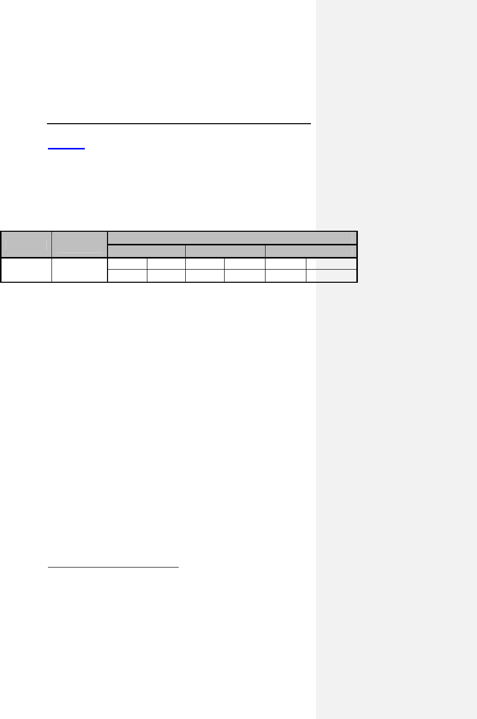
Evia Technical Manual 147
Table 32 shows the expected longevity (in years) from BOS to
ERI for Evia pulse generators. The programmer software for the
Evia pulse generators provides an estimated time to ERI in
months and years that is updated each time the device is
reprogrammed. This estimation allows the physician to
understand the longevity effects of modifying programmed
parameters.
Table 32: Nominal Pulse Generator Longevity
Amplitude Impedance
(Ohms) Pacing
10% 50% 100%
2.5 V 500 DR(-T) SR(-T) DR(-T) SR(-T) DR(-T) SR(-T)
12.1 15.0 10.7 14.1 8.2 11.9
The mean2 expected time intervals from ERI to EOS at standard
program for Evia pulse generators is 6 months. All service
intervals, including the above-cited nominal pulse generator
longevity, are based on considerations that consider the battery
discharge behavior and the hybrid circuit properties including
current consumption and replacement indicator. The statistical
calculations are based on a basic rate of 60 ppm, pulse width of
0.4 ms, shelf life of 1.5 years, and data supplied by the battery
manufacturer.
2 50% of all pacemakers reach or exceed the given value

148 Evia Technical Manual

Evia Technical Manual 149
14. Explantation
Explanted pulse generators or explanted accessories may not
be reused. Explanted pulse generators can be sent either to the
local BIOTRONIK representative or the BIOTRONIK home office
for expert disposal. If possible, the explanted pulse generator
should be cleaned with a sodium-hyperchlorine solution of at
least 1% chlorine and, thereafter, washed with water prior to
shipping.
The pulse generator should be explanted before the cremation of
a deceased patient.
CAUTION
Device Incineration - Never incinerate a pulse generator. Be
sure the pulse generator is explanted before a patient who
has died is cremated.
Explanted Devices – Return all explanted devices to
BIOTRONIK.
14.1 Common Reasons to Explant a
Pulse Generator
A pulse generator may be explanted emergently or at a
physician's discretion at any time subsequent to an implant
procedure. Reasons for explant include, but are not limited to:
patient death; no output/intermittent output; loss of capture/
sensing; inability to program/interrogate the pulse generator;
infection, EOS (normal or premature); system upgrade;
physician preference for another pulse generator model; and/or
other reason(s) which may or may not be known to the pulse
generator manufacturer. Complications related to other portions
of the pacing system (i.e., lead, patient) may also result in pulse
generator explant. Table 33 summarizes some of the more
common reasons for pulse generator explant.

150 Evia Technical Manual
Table 33: Common Reasons to Explant a Pulse Generator
Source Cause Possible Effect
Battery Premature
depletion due to
high
programmed
output or other
cause(s)
resulting in
excessive
battery current
drain.
Output voltage decrease;
rate decrease; loss of
capture; increased pulse
width; inability to
program/interrogate;
sensing difficulty.
Circuitry Electrical
parameter
changes due to
shorts, opens, or
component
parametric drift
Electromagnetic
Interference
(EMI) from large
power tools,
industrial
equipment,
electrocautery,
defibrillation,
radiation
therapy, RF
ablation therapy,
etc.
No output; rate increase,
rate decrease; reversion to
asynchronous mode; loss of
capture and/or sensing
Permanent or temporary loss
of output; output inhibition;
reversion to asynchronous
mode with rate change or
instability; pacing
synchronized to interference;
reversion to "Elective
Replacement" or electrical
reset parameters; inability to
program/ interrogate; other
damage to circuit
components resulting in
permanent or temporary
parameter changes.
Connector,
Setscrew,
etc.
Poor connection,
intrusion of body
fluid.
Excessive current drain;
early battery depletion;
intermittent or continuous
loss of capture and/ or
sensing.

Evia Technical Manual 151
Source Cause Possible Effect
Leads Displacement,
fracture, loss of
insulation
integrity.
Intermittent or continuous
loss of capture and/or
sensing; excessive current
drain; early battery
depletion.
Cardiac
perforation
The above plus cardiac
tamponade; muscle or nerve
stimulation.
Myocardial
irritability at time
of insertion, e.g.,
from an acute
myocardial
infarction
Fibrillation
Patient Threshold
Elevation
Loss of capture and/or
sensing.
Normal medical
complication
Infection
Body rejection
phenomena
Fluid accumulation;
migration; erosion.
Misc. Unipolar pacing
systems
Inhibition of pulse generator
due to sensing of skeletal
muscle activity.
Physician
preference
Upgrade to bipolar, dual
chamber, rate-adaptive pulse
generator, etc.
Introducer
caused
Air embolism or
pneumothorax.

152 Evia Technical Manual

Evia Technical Manual 153
15. Technical Data
15.1 Modes
Modes DR DR-T
3
SR SR-T Modes DR DR-T
3
SR SR-T
DDD-CLS X X DVI X X
VVI-CLS X X X X VDD X X
DDDR X X
VVI X X X X
DDIR X X
VDI X X
DVIR X X
AAI X X X X
VDDR X X
DOO X X
VVIR X X X X VOO X X X X
AAIR X X X X AOO X X X X
VDIR X X
DDT X X
VVT X X X X
VVTR X X X X AAT X X X X
OFF X X X X
AATR X X X X
DOOR X X
VOOR X X X X
AOOR X X X X
NOTE:
Programmability dependent on programmer software
utilized.
Bold parameters indicate factory settings.
Parameters specified at 37º C, with a lead impedance of
500 ohms.
3 The Home Monitoring function is available for the following pacing modes. With
Home Monitoring deactivated, all Evia DR pacing modes are available.
Kommentar [MJ2]: Please confirm
these modes.

154 Evia Technical Manual
15.2 Pulse- and Control Parameters
Basic rate
30...(1)...60...(1)...88...(2)...122...(3)...140...(5)...200 ppm
Night rate
Off, 30...(1)...60...(1)...88...(2)...122...(3)...140...(5)...200 ppm
Rate Hysteresis
Off; -5...(5)...-90 bpm
Repetitive Hysteresis
Off; 1…(1)…15
Scan Hysteresis
Off: 1…(1)…15
Upper Rate
90…(10)…200 ppm
UTR Response
WRL (automatic selection)
Rate Limitation4,5,6
190…220 ppm
Dynamic AV Delay (Dual chamber only)
Off; low; medium; high, (individual, or fixed), IOpt
4 The corresponding intervals t correlate with the rates f by the formula t = 60.000
/ f (t in ms, f in ppm).
5 In the event of electronic defect.
6 Rate Limitation changes as the Pacemaker approaches End of Service. The
Rate Limitation is nominally 190 ppm at Beginning of Service (BOS) and can
reach 220 ppm at End of Service (EOS) due to battery depletion.

Evia Technical Manual 155
AV Delay Values (Dual chamber only)
15…(5)…350 ms
(Programmable in 5 ranges)
AV Delay Hysteresis (Dual chamber only)
Off; low; medium; high; negative, IOPT
AV Repetitive Hysteresis (Dual chamber only)
Off; 1…(1)…10
AV Scan Hysteresis (Dual chamber only)
Off; 1…(1)…10
Repetitive AV Delay Hysteresis (Negative AV Hysteresis)
Off, 1…(1)…10…(5)…100…(10)…180
AV safety delay (Dual chamber only)
100 ms
Sense Compensation
Off; -10...(5)…45…(5)...-120 ms
Far Field after Vs
100…(10)…220 ms
Far Field after Vp
100…(10)…150…(10)…220 ms
Ventricular Blanking after Ap
30…(5)…70 ms

156 Evia Technical Manual
Magnet effect
Automatic; asynchronous; synchronous
Asynchronous Magnet Effect: paces at 90 ppm.
Automatic Magnet Effect; 10 cycles at 90 ppm asynchronous;
thereafter synchronous with the programmed basic rate
Synchronous Magnet Effect; synchronous with programmed
basic rate
Pulse amplitude
A 0.2...(0.1)...3.0...(0.1)...6.0...(0.5)...7.5 V
V 0.2...(0.1)...3.0...(0.1)...6.0...(0.5)...7.5 V
Pulse width
A 0.1; 0.2; 0.3; 0.4; 0.5; 0.75; 1.0; 1.25; 1.5 ms
V 0.1; 0.2; 0.3; 0.4; 0.5; 0.75; 1.0; 1.25; 1.5 ms
Sensitivity
A AUTO, 0.5...(0.1)...1.5...(0.5)...7.5 mV
V AUTO, 0.5...(0.5)...2.5...(0.5)...7.5 mV
Refractory period7
A AUTO
V 200…(25)…250…(25)…500 ms
PVARP
AUTO, 175…(5)…250…(5)…600 ms
Automatic Lead Check
Off; On
Mode Switch (X out of Y)
Off; On
X = 3...(1)...8

Evia Technical Manual 157
Z= 3...(1)...8
Intervention Rate
100, 110...(10)...160…(10)…250 ppm
Mode Switch Basic Rate
Off, +5…(5)…+10…(5)…+30
2:1 Lock-In Protection
Off; On
Lead Polarity8
Pace: A unipolar; bipolar
V unipolar; bipolar
Sense: A unipolar; bipolar
V unipolar; bipolar
15.2.1 Rate Adaptation
Sensor gain
1.0, 1.1, 1.3, 1.4, 1.6, 1.8, 2.0, 2.2, 2.3, 3.0, 3.3, 3.7, 4.0, 4.5,
5.0, 6.0, 7.0, 8.0, 8.5, 10, 11, 12, 14, 16, 18, 20, 23
Sensor threshold
very low; low; medium; high; very high
Rate increase
1…(1)…10 ppm/cycle
Maximum sensor rate
80...(5)...160 ppm
Rate decrease
0.1, 0.2, 0.5, 1.0 ppm/cycle
8 Philos DR-A/SR-B polarity is limited to unipolar only.

158 Evia Technical Manual
Automatic Sensor Gain
Off; On
15.2.2 Ventricular Capture Control (VCC)
Ventricular Capture Control
Off, On, ATM
Maximum VCC Amplitude
2.4, 3.0, 3.6, 4.2 4.8 V
Safety Margin
OFF, 0.3…(0.1)…0.5…(0.1)… 1.2V
Search Scheduling
Interval, Time of Day
Interval
0.1, 0.3, 1, 3, 6, 12, 24 hours
Time of Day
00:00 … 23:50 in 10 minute increments, nominal 02:00
15.2.3 Home Monitoring Parameters
Home Monitoring
Off, On
Monitoring Interval
1 day
Time of the Trend Report Transmission
Auto, 00:00...(30)...23:30 hours
Periodic Transmission
Off, 30, 60, 90, 120, 180 days

Evia Technical Manual 159
Ongoing Atrial Episode
6, 12, 18 hours
Event Report
Off, On
Patient Report
Off, On

160 Evia Technical Manual
15.2.4 Additional Functions
NOTE:
Availability of the following functions is dependent upon
pulse generator configuration.
• Temporary Program Activation
• High Precision Threshold test in the range up to 7.5 V
with 0.1 V resolution
• PAC (pulse amplitude control) system produces
consistent pulses
• Two channel Real Time IEGM Transmission with
markers
• Patient Data Memory
• Sensor Simulation
• Position Indicator for the programmer head
• 24-hour Trend
• Heart Rate Histogram
• Sensor Rate Histogram
• Sensor Test Trend with complete Rate Forecast
• Automatic Sensor Gain with Trend Monitor
• VES Analysis
• Retrograde Conduction Test
• Mode Switching
• Activity Report
• Event counter
• P-/R-wave Tests with Trend Data
• External Pulse Control up to 800 ppm
• Night Program
• IEGM Recordings
• Lead Impedance Trends
• Automatic Lead Check
• Rate Fading
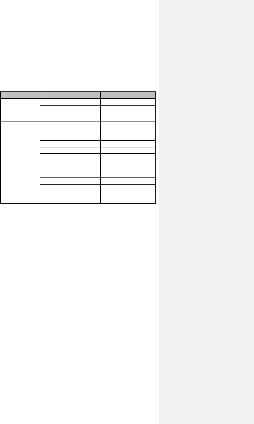
Evia Technical Manual 161
15.2.5 NIPS Specifications
Burst Mode Burst Chambe
r
A
trium
Burst
stimulation
A. Only
Coupling Interval / ms None… 2000
Burst Type Pushbutton, Ramp
Burst Range / ppm 125…800
Programmed
Stimulation
A. Only
S1-S1 S1-S2, S2-S3,
S3-S4, S4-S5
Cycles 0…10
Pause / ms Stop… 50
No. of intervals 4
Decrement ms 0…100
Back-up
Pacing
Modes VOO,VVI
Rate / ppm 30…200
Amplitude / V 0.2…7.5
Pulse width / ms 0.1, 0.2, 0.3, 0.4,
0.5, 0.75, 1.0, 1.5
Pace Polarity Bipolar, Unipolar
15.3 Programmer
ICS 3000
15.4 Materials in Contact with Human
Tissue
Housing: Titanium
Connector receptacle: Epoxy resin
Sealing Plugs: Silicone Rubber
15.5 Electrical Data/Battery
NOTE:
At 37º C, with pacing impedance of 500 Ohms.

162 Evia Technical Manual
Parameter Evia DR Evia DR-T Evia SR Evia SR-T
Pace Unipolar/bipolar same same same
Pulse form Biphasic,
asymmetric
same same same
Polarity Cathodic same same same
Input
impedance
>10 kΩ (A);
>10 kΩ (V)
>10 kΩ (A);
>10 kΩ (V)
>10 kΩ >10 kΩ
Power source LiJ Ag/SVO/C
Fx (QMR),
MDX
Same as
Evia DR
Same as
Evia DR-T
Battery voltage
at BOS
2.8 V 3.0 V 2.8 V 3.0 V
Conducting
surface
(uncoated)
33 cm
2
same same same
Conducting
surface (coated)
7 cm
2
same same same
Conducting
Shape
(coated)
(uncoated)
Ellipsoidal
Flattened
ellipsoidal
same
same
same
same
same
same

Evia Technical Manual 163
15.6 Mechanical Data
Model Leads Size Ma
ss Volume
Evia DR IS-1 6.5 x 43 x 53 mm 26
g
11 cc
Evia DR-T IS-1 6.5 x 44.5 x 53 mm 25
g
12 cc
Evia SR IS-1 6.5 x 39 x 53 mm 25
g
10 cc
Evia SR-T IS-1 6.5 x 39 x 53 mm 24
g
11 cc

164 Evia Technical Manual
16. Order Information
Pulse Generator Type Order Number
Evia DR 359 524
Evia DR-T 359 529
Evia SR 359 531
Evia SR-T 359 533

Evia Technical Manual 165
FCC Statement: (FCC ID: QRIPRIMUS): This transmitter is
authorized by rule under the Medical Device
Radiocommunication Service (in part 95 of the FCC Rules)
and must not cause harmful interference to stations
operating in the 400.150-406.000 MHz band in the
Meteorological Aids (i.e., transmitters and receivers used to
communicate weather data), the Meteorological Satellite, or
the Earth Exploration Satellite Services and must accept
interference that may be caused by such stations, including
interference that may cause undesired operation. This
transmitter shall be used only in accordance with the FCC
Rules governing the Medical Device Radiocommunication
Service. Analog and digital voice communications are
prohibited. Although this transmitter has been approved by
the Federal Communications Commission, there is no
guarantee that it will not receive interference or that any
particular transmission from this transmitter will be free from
interference.
This device complies with part 15 of the FCC Rules.
Operation is subject to the following two conditions:
(1) This device may not cause harmful interference, and
(2) this device must accept any interference received,
including interference that may cause undesired operation

166 Evia Technical Manual
Appendix A
Mode-Specific Indications and
Contraindications
Rate-adaptive Pacing
Evia DR and
Evia DR-T: DDDR, DDIR, DVIR, VDDR, VVIR, DDD-CLS,
VVI-CLS, AAIR
Evia SR and
Evia SR-T: VVIR, VOOR, VVI-CLS, VVTR, AATR, AOOR,
AAIR
NOTE:
For indications specific to the VDDR mode, see Indications
for Use on page 1 (Section 2).
Indications for rate-adaptive pacing may include but are not
limited to the following:
• Patients with chronotropic incompetence who have an
anticipated moderate or high level of activity and in
whom there is a stable atrial rhythm, and for whom DDD,
DDI, DVI, VDD, or VVI pacing is also indicated.
• Patients who have persistent VA conduction (dual
chamber modes).
These indications include but are not limited to sick sinus
syndrome and AV block.
The rate-adaptive modes of the Evia family of pulse
generators are contraindicated for patients who are known to
develop angina or ischemia at accelerated pacing rates. In
addition, the rate-adaptive modes are contraindicated in
circumstances where the applicable non-rate-adaptive mode
is noted as contraindicated in the following text.

Evia Technical Manual 167
Dual Chamber
DDD
The DDD mode is clearly indicated if
• AV synchrony is needed over a broad range of rates,
such as
1. active or young patients with an adequate increase in
atrial rate, and/or
2. significant hemodynamic indication, and/or
3. previous occurrence of pacemaker syndrome or of a re-
duction in systolic blood pressure of more than 20 mm
Hg under ventricular pacing with pulse generator
implantation (regardless of any evidence of retrograde
VA conduction).
The DDD mode is conditionally indicated in the case of
• a complete AV block or of sick sinus syndrome and
stable atrial rate, and/or
• proof that simultaneously setting the atrial and
ventricular rates can inhibit tachyarrhythmia or if the
pulse generator can be set to a pacing mode suited for
interrupting arrhythmia.
The DDD mode is contraindicated in the case of
• frequent or persistent supraventricular tachyarrhythmia,
including atrial fibrillation or flutter, and/or
• inadequate intra-atrial complexes that do not permit safe
sensing, and/or
• angina pectoris which would be aggravated by increased
heart rates.9
DDI
The DDI mode is useful in all cases in which dual chamber
pacing is necessary, but where intermittent supraventricular
arrhythmias frequently occur.
9 The ACC/AHA Guidelines cannot replace a study of the relevant specialized
literature, especially since the indications and contraindications for using
particular pacing modes are subject to constant advances in medical
knowledge.

168 Evia Technical Manual
DVI
The DVI mode is clearly indicated if
• AV sequential contraction is necessary due to
symptomatic bradycardia and slow atrial rate, and/or
• a pacemaker syndrome has already been documented.
The DVI mode is conditionally indicated for
• frequent supraventricular arrhythmia in which a
combination of pacing and medication has proved
therapeutically effective, and/or
• the presence of a bradycardia-tachycardia syndrome,
presuming that setting the atrial rate and the AV interval
with or without accompanying medication stops or
prevents supraventricular arrhythmia.
The DVI mode is contraindicated for
• frequent or persistent supraventricular tachyarrhythmia,
including atrial fibrillation or flutter.
Dual Chamber Modes
VDD
The VDD mode is clearly indicated for
• ventricular pacing when adequate atrial rates and
adequate intracavitary complexes are present. The
indication includes the presence of complete AV block
when
1. the atrial contribution is necessary for hemodynamic
optimization, and/or
2. a pacemaker syndrome has already occurred or is
expected.

Evia Technical Manual 169
The VDD mode is conditionally indicated for
• patients with normal sinus rhythms and normal AV
conduction, but who intermittently need ventricular
pacing.
The VDD mode is contraindicated for
• frequent or persistent supraventricular tachyarrhythmia,
including atrial fibrillation or flutter, and/or
• inadequate intra-atrial complexes that do not permit safe
sensing, and/or
• intact retrograde conduction.
Single Chamber Modes
VVI
The VVI mode is clearly indicated for
• all symptomatic bradyarrhythmias, but particularly if
1. the atrium does not significantly contribute to the hemo-
dynamics (persistent or paroxysmal atrial flutter or
fibrillation, dilated atria).
4. there are no grounds for development of pacemaker
syndrome through loss of the atrial contribution or
through negative atrial contribution.
The VVI mode is conditionally indicated for
• symptomatic bradycardia when the simplicity of the
pacing system is of crucial significance due to
1. senility (for the sole purpose of prolonging life).
2. incurable illness.
3. great distance from the follow-up care center to the
patient's home.
4. absence of retrograde VA conduction.

170 Evia Technical Manual
The VVI mode is contraindicated if
• a pacemaker syndrome is known to exist or if the patient
develops particular symptoms during temporary pacing
or pulse generator implantation, and/or
• there is a need to maximize the atrial contribution due to
1. congestive heart failure, and/or
2. a specific need for ventricular rate adaptation.
AAI
The AAI mode is clearly indicated for
• symptomatic sino-atrial node dysfunction (sick sinus
syndrome), given that adequate AV conduction has
been established by an appropriate examination.
The AAI mode is conditionally indicated if
• the hemodynamics of patients with bradycardia and
symptomatically reduced cardiac output can be
improved by raising the heart rate, given that adequate
AV conduction has been established by an appropriate
diagnostic examination.
The AAI mode is contraindicated for
• previously established AV conduction delay or AV block
or if diminishing AV conduction has been determined by
appropriate tests, and/or
• inadequate intra-atrial complexes that do not permit safe
sensing.

Evia Technical Manual 171
Other Modes
In addition to the ACC/AHA guidelines, the modes listed above
may have further indications due to medical/technical
complications such as electromagnetic interference, sensing
defects, fracture of the lead(s), detection of myopotentials,
muscle stimulation, etc. The same applies to the asynchronous
DOO(R), AOO(R) and VOO(R) pacing modes derived from the
above by restricting the sensing functions [SOO(R) mode
available with Evia SR models]. The triggered DDT, DDI/T,
VDT, DVT, AAT and VVT pacing modes and the VDI and OFF
modes are indicated for diagnostic purposes to assess intrinsic
cardiac activity. Use of the OFF mode is contraindicated in
pacemaker dependent patients.

172 Evia Technical Manual
Appendix B
Known Software Anomalies
Anomaly Possible Effect on
Patient or Implant
Procedure
GENERAL PROGRAMMER ISSUES
Data Export (via .pdf file) cannot
be performed if insufficient
programmer memory is
available. The programmer
correctly aborts the data export
process but incorrectly displays
the message: “Data Export
successful”
No effect on patient,
inconvenience to clinical
personnel. No incorrect
data is exported, and the
information is available on
the printout and the
programmer display.
ICS 3000 programmer may not
recharge battery when device is
in hibernation shut down mode
(OFF button quickly pressed).
No effect on patient, If
battery has depleted to a
low level, system boot may
not be possible. The system
will need to be connected to
a wall electrical outlet.
Minor inconvenience to field
clinical personnel.
If an Operation Module carrying
a new but highly depleted battery
(less than 10% capacity) when
detached from the docking
station an incorrect warning
message may be displayed "The
battery urgently needs to be
replaced,"
No effect on patient, but the
ICS 3000 may be returned
unnecessarily for battery
replacement. The depletion
status of the battery is
clearly discernible to the
user (battery LEDs).

Evia Technical Manual 173
Anomaly Possible Effect on
Patient or Implant
Procedure
Display and activation of the
"Implantation Module" button on
the Operation Module (OM)
screen may be delayed for
30 sec after the OM has been
reattached to the docking station
and placed in to hibernation
mode. The button will appear
light grey until it becomes active.
No effect on patient, but the
delay in activating the
button may cause user
confusion.
Evia Software Application
If the sensing test fails during
automatic follow-up test
sequence, the error messages
are displayed too quickly to read
(less than 1 second).
No effect on patient, the test
will need to be re-run as no
result will be displayed.
Evia Pacemakers
Application of the programming
wand in a narrow time window
may result in a missing data
point on the trend graph. In very
rare instances, this error can
lead to statistics not being
displayed until statistics are
restarted.
Diagnostic data may not be
available for a short amount
of time. The situation is
temporary, and there is no
patient risk involved.

Distributed by:
BIOTRONIK, Inc.
6024 Jean Road
Lake Oswego, OR 97035-5369
(800) 547-0394 (24-hour)
(503) 635-9936 (FAX)
Manufactured by:
BIOTRONIK SE & Co. KG
Woermannkehre 1
12359 Berlin Germany
M4131-A 1/10