BIOTRONIK SE and KG TACH70 implantable cardioverter defibrillator User Manual
BIOTRONIK SE & Co. KG implantable cardioverter defibrillator
UserManual.wiki
>
BIOTRONIK SE and KG
>
TACH70 User Manual
15_[TACH70] UserMan
Navigation menu
Upload a User Manual
Namespaces
Wiki Guide
HTML
PDF
Info
Views
User Manual
Discussion / Help
Navigation
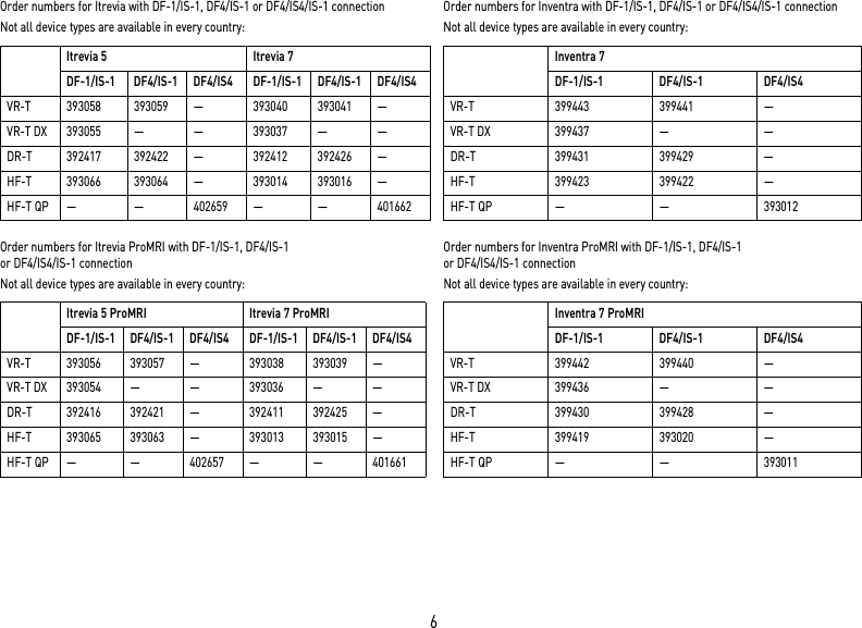
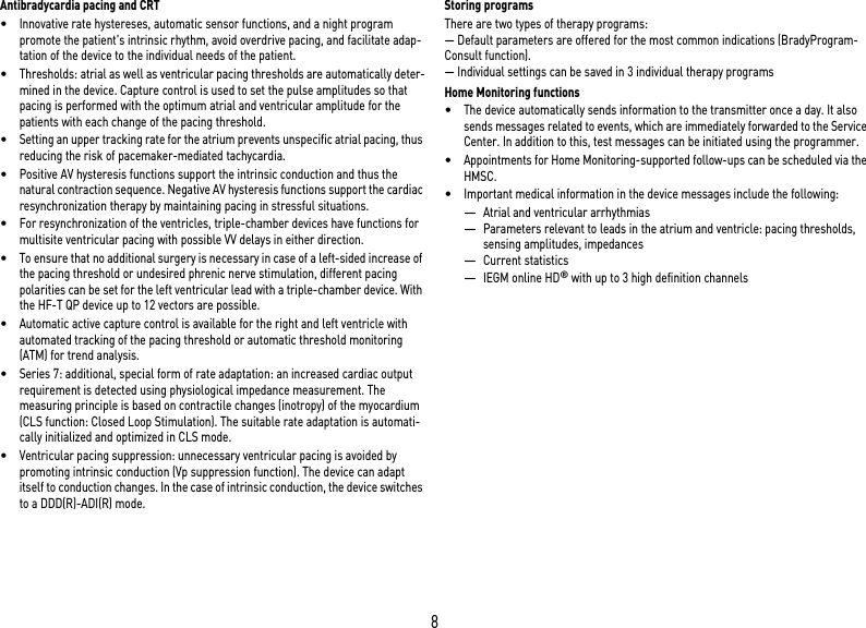
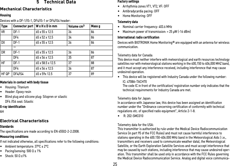
![20Timing: Upper rateTiming: Mode switchingTiming: Ventricular pacing supressionTiming: Ventricular pacingTiming: Refractory periods and blanking periodsTiming: PMT protectionParameter Range of values StandardVRDXDRHFUpper rate N.n. bpm N.n. bpm x x xAtrial upper rate OFF; N.n. bpm N.n. bpm x xParameter Range of values StandardVRDXDRHFIntervention rate OFF; N.n. bpm N.n. bpm x x xOnset criterion N.n. N.n. x x xResolution criterionModification of basic rate OFF; N.n. bpm N.n. bpm x x xMode After mode VDD(R): VDI(R) VDI x x xAfter mode DDD(R): DDI(R) DDI x xAfter mode switching:– Rate OFF; N.n. bpm N.n. bpm x x x– Duration N.n. min N.n. minParameter Range of values StandardVRDXDRHFVp suppression OFF; ON OFF x xPacing suppression [consec-utive Vs]N.n. N.n. x xPacing support [out of 8 cycles]N.n. N.n. x xParameter Range of values StandardVRDXDRHFPermanent RV; BiV; LV BiV xTriggering OFF; RVs; RVs+PVC RVs xLV T-wave protection OFF; ON ON xMaximum trigger rate:– DDD(R) and VDD(R) UTR N.n. bpm UTR + N.n.x– DDI(R), VDI(R) and VVI(R) N.n. bpm N.n. bpmInitially paced chamber RV; LV LV xVV delay after Vp N.n. ms N.n. ms xParameter Range of values StandardVRDXDRHFPVARP AUTO; N.n. ms N.n. ms x x xBlanking after atrial pacing N.n. ms N.n. ms x xLV blanking after RV pacing N.n. ms xRV blanking after LV pacingFar-field protection after Vs OFF; N.n. ms N.n. ms x x xFar-field protection after Vp N.n. ms N.n. ms x x xParameter Range of values StandardVRDXDRHFPMT detection/termination OFF; ON ON x x xVA criterion N.n. ms N.n. ms x x x](https://usermanual.wiki/BIOTRONIK-SE-and-KG/TACH70/User-Guide-2250181-Page-20.png)
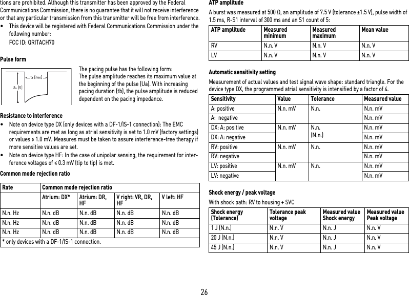
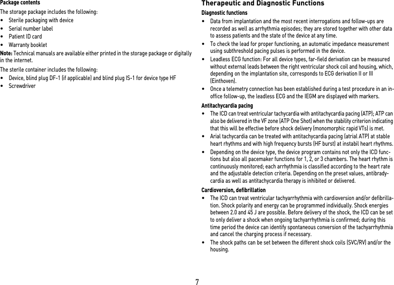
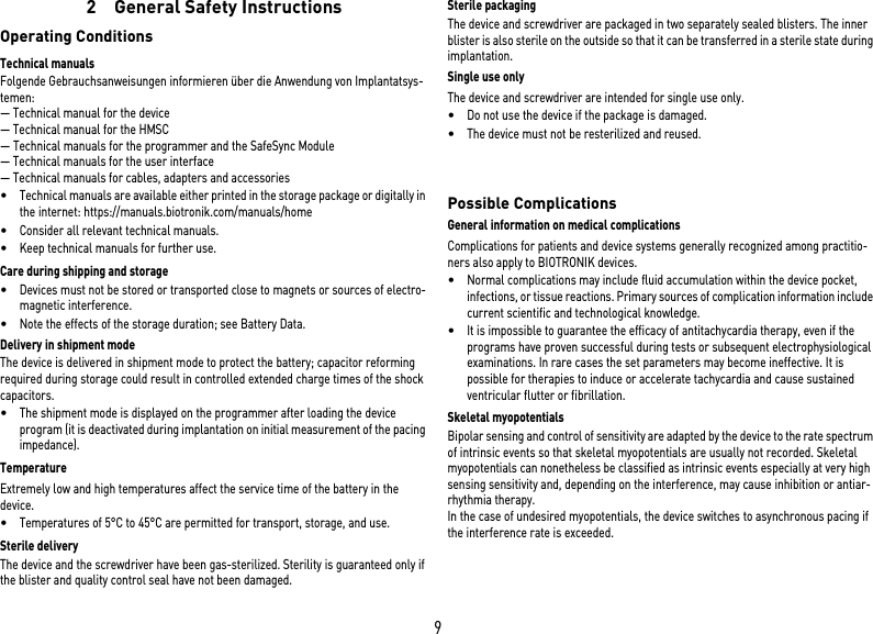
![27Battery DataBattery characteristicsThe following data is provided by the manufacturers: Storage periodThe storage period affects the battery service time.•Devices should be implanted within N.n. months between the manufacturing date and the use by date (indicated on the package).•If the ICD is implanted shortly before the use by date, the expected service time may be reduced by up to N.n. months.Calculation of service times•The services times have been calculated as follows – in all chambers depending on the device type:—Pulse amplitude: 2.5 V—Pulse width: 0.4 ms—Pacing impedance: 500 Ω—Basic rate: 60 bpm—Home Monitoring: ON, 1 device message each day and 12 IEGM online HD transmissions per year—Diagnostic functions and recordings: permanently set•Capacitor reforming is performed N.n. times per year and therefore at least N.n. maximum charges for shocks have to be assumed per year even if less than N.n. are delivered.Calculation of the number of shocksCalculation of the maximum number of shocks: Service time [in years] x number of shocks per yearService times single-chamberService times with GB 2992 or LiS 3410 RR battery, subject to change: Service times dual-chamberService times with GB 2992 or LiS 3410 RR battery (only devices with DF-1/IS-1 connection), subject to change: Service times triple-chamberService times with GB 2992 or LiS 3410 RR battery, subject to change: Manufacturer GREATBATCH, INC. Clarence, NY 14031 LITRONIK GmbH & Co01796 Pirna, GermanyBattery type GB 2992 LiS 3410 RRBattery ID number shown on the programmer3 N.n.Device type VR, (DX), DR, HFBattery voltage at ERI 2.5 V N.n. VCharge time at BOS 10 s N.n. sCharge time at ERI 12 s N.n. sUsable capacity until ERI 1590 mAh N.n. mAhUsable capacity until EOS 1730 mAh N.n. mAhPacingService time [in years] at number of shocks per year481216200, 15, 50, 100%N.n. N.n. N.n. N.n. N.n.PacingService time [in years] at number of shocks per year481216200, 15, 50, 100%N.n. N.n. N.n. N.n. N.n.PacingService time [in years] at number of shocks per year481216200, 15, 50, 100%N.n. N.n. N.n. N.n. N.n.](https://usermanual.wiki/BIOTRONIK-SE-and-KG/TACH70/User-Guide-2250181-Page-27.png)