BIOTRONIK SE and KG TACHNT2 Implantable Cardioverter Defibrillator User Manual 417634 B GA Intica ProMRI mul
BIOTRONIK SE & Co. KG Implantable Cardioverter Defibrillator 417634 B GA Intica ProMRI mul
Contents
- 1. 15a_[TACHNT2] UserMan_Inlexa
- 2. 15b_[TACHNT2] UserMan_Ilivia
- 3. 15c_[TACHNT2] UserMan_Intica
15c_[TACHNT2] UserMan_Intica
Intica 5/7
ICD Family • Tachyarrhythmia Therapy • Cardiac Resynchronization Therapy
ICD-Familie • Tachyarrhythmietherapie • Kardiale Resynchronisationstherapie
Familia de DAI • Terapia antitaquiarritmia • Terapia de resincronización cardiaca
Famille des DAI • Traitement de la tachyarythmie • Traitement par resynchronisation cardiaque
Technical manual
Gebrauchsanweisung
Manual técnico
Manuel technique
• en
• de
• es
• fr
BIOTRONIK SE & Co. KG
Woermannkehre 1
12359 Berlin · Germany
Tel +49 (0) 30 68905-0
Fax +49 (0) 30 6852804
sales@biotronik.com
www.biotronik.com
16-D-xx
Revision: B (2015-11-06)
© BIOTRONIK SE & Co. KG
All rights reserved. Specications subject
to modication, revision and improvement.
® All product names in use may be trademarks or
registered trademarks held by BIOTRONIK or
the respective owner.
0123
0681 2016

en • English
1
en • English
Table of Contents
Product Description . . . . . . . . . . . . . . . . . . . . . . . . . . . . . . . . . . . . . . . . . . . . . . . . . . . . . . 1
Intended Medical Use . . . . . . . . . . . . . . . . . . . . . . . . . . . . . . . . . . . . . . . . . . . . . . . 1
System Overview. . . . . . . . . . . . . . . . . . . . . . . . . . . . . . . . . . . . . . . . . . . . . . . . . . . 2
Therapeutic and Diagnostic Functions . . . . . . . . . . . . . . . . . . . . . . . . . . . . . . . . . 7
General Safety Instructions . . . . . . . . . . . . . . . . . . . . . . . . . . . . . . . . . . . . . . . . . . . . . . . . 8
Operating Conditions . . . . . . . . . . . . . . . . . . . . . . . . . . . . . . . . . . . . . . . . . . . . . . . 8
Possible Complications . . . . . . . . . . . . . . . . . . . . . . . . . . . . . . . . . . . . . . . . . . . . . 9
Possible Risks. . . . . . . . . . . . . . . . . . . . . . . . . . . . . . . . . . . . . . . . . . . . . . . . . . . . 10
Implantation. . . . . . . . . . . . . . . . . . . . . . . . . . . . . . . . . . . . . . . . . . . . . . . . . . . . . . . . . . . . 11
Implantation Procedure . . . . . . . . . . . . . . . . . . . . . . . . . . . . . . . . . . . . . . . . . . . . 11
Precautionary Measures while Programming . . . . . . . . . . . . . . . . . . . . . . . . . . 13
Magnet Response . . . . . . . . . . . . . . . . . . . . . . . . . . . . . . . . . . . . . . . . . . . . . . . . . 16
Follow-up . . . . . . . . . . . . . . . . . . . . . . . . . . . . . . . . . . . . . . . . . . . . . . . . . . . . . . . 16
Patient Information. . . . . . . . . . . . . . . . . . . . . . . . . . . . . . . . . . . . . . . . . . . . . . . . 17
Replacement Indications . . . . . . . . . . . . . . . . . . . . . . . . . . . . . . . . . . . . . . . . . . . 17
Explantation and Device Replacement . . . . . . . . . . . . . . . . . . . . . . . . . . . . . . . . 18
Parameters . . . . . . . . . . . . . . . . . . . . . . . . . . . . . . . . . . . . . . . . . . . . . . . . . . . . . . . . . . . . 18
Bradycardia / CRT. . . . . . . . . . . . . . . . . . . . . . . . . . . . . . . . . . . . . . . . . . . . . . . . . 18
MRI program . . . . . . . . . . . . . . . . . . . . . . . . . . . . . . . . . . . . . . . . . . . . . . . . . . . . . 22
Tachycardia . . . . . . . . . . . . . . . . . . . . . . . . . . . . . . . . . . . . . . . . . . . . . . . . . . . . . . 23
Sensing . . . . . . . . . . . . . . . . . . . . . . . . . . . . . . . . . . . . . . . . . . . . . . . . . . . . . . . . . 24
Diagnostics . . . . . . . . . . . . . . . . . . . . . . . . . . . . . . . . . . . . . . . . . . . . . . . . . . . . . . 25
Home Monitoring . . . . . . . . . . . . . . . . . . . . . . . . . . . . . . . . . . . . . . . . . . . . . . . . . 25
Technical Data . . . . . . . . . . . . . . . . . . . . . . . . . . . . . . . . . . . . . . . . . . . . . . . . . . . . . . . . . . 26
Mechanical Characteristics . . . . . . . . . . . . . . . . . . . . . . . . . . . . . . . . . . . . . . . . . 26
Electrical Characteristics. . . . . . . . . . . . . . . . . . . . . . . . . . . . . . . . . . . . . . . . . . . 26
Battery Data . . . . . . . . . . . . . . . . . . . . . . . . . . . . . . . . . . . . . . . . . . . . . . . . . . . . . 28
Legend for the Label . . . . . . . . . . . . . . . . . . . . . . . . . . . . . . . . . . . . . . . . . . . . . . 30
1 Product Description
Intended Medical Use
Intended use
Intica belongs to a family of implantable cardioverter-defibrillators (ICD). The primary
objective of the therapy is to prevent sudden cardiac death. Furthermore, the device is
capable of treating bradycardia arrhythmias and cardiac resynchronization therapy
with multisite ventricular pacing.
The implantation of an ICD is a symptomatic therapy with the following objectives:
•
Termination of spontaneous ventricular fibrillation (VF) through shock delivery
•
Termination of spontaneous ventricular tachycardia (VT) through antitachycardia
pacing (ATP); in case of ineffective ATP or hemodynamically not tolerated VT, with
shock delivery
•
Cardiac resynchronization through multisite ventricular pacing (triple-chamber
devices)
•
Compensation of bradycardia through ventricular (single-chamber devices) or AV
sequential pacing (DX, dual- and triple-chamber devices).
VR-T DX and HF-T/HF-T QP devices types with DX functionality are only indicated
for patients not requiring atrial pacing.
Diagnosis and therapy forms
The device monitors the heart rhythm and automatically detects and treats cardiac
arrest resulting from ventricular tachyarrhythmia. All major therapeutic approaches
from the field of cardiology and electrophysiology are included. BIOTRONIK
Home Monitoring
®
enables physicians to perform therapy management at any time.
Required expertise
In addition to having basic medical knowledge, the user must be thoroughly familiar
with the operation and the operation conditions of a device system.
•
Only qualified medical specialists having this required special knowledge are
permitted to use implantable devices.
•
If users do not possess this knowledge, they must be trained accordingly.
417634--B_GA_Intica-ProMRI_mul.fm Page 1 Friday, November 6, 2015 8:13 PM

2
Indications
Intica can treat life-threatening ventricular arrhythmias with antitachycardia pacing
and defibrillation.
Generally approved differential diagnostics methods, indications, and recommenda-
tions for ICD therapy apply to BIOTRONIK devices. See the current guidelines of
cardiology associations for guidance.
We recommend observing the indications published by the German Cardiac Society
(Deutsche Gesellschaft für Kardiologie, Herz- und Kreislaufforschung, (DGK)) and the
European Society of Cardiology (ESC). This also applies to the guidelines published by
the Heart Rhythm Society (HRS), the American College of Cardiology (ACC), the
American Heart Association (AHA), and other national cardiology associations.
Single-chamber and dual-chamber
Single-chamber and dual-chamber ICDs are indicated for patients with the following
risk:
•
Sudden cardiac death caused by ventricular arrhythmias
Triple-chamber
Triple-chamber ICDs are indicated for patients with the following risks:
•
Sudden cardiac death caused by ventricular arrhythmias
•
Congestive heart failure with ventricular asynchrony
Contraindications
Known contraindications:
•
Tachyarrhythmia caused by temporary or reversible irritation, e.g. poisoning, elec-
trolyte imbalance, hypoxia, sepsis or acute myocardial infarction
•
Such frequent VT or VF that the therapies would cause an unacceptably rapid
depletion of the device batteries
•
VT with few or without clinically relevant symptoms
•
VT or VF treatable by surgery
•
Concomitant diseases that would substantially limit a positive prognosis
•
Accelerated intrinsic rhythm
System Overview
Device family
The complete Intica 5/7 ProMRI device family consists of several device types with
a DF-1/IS-1 or DF4/IS-1 connection or with DF4/IS-1 or DF4/IS4/IS-1 connection.
•
Single-chamber: VR-T and VR-T DX (device type with only a DF-1/IS-1 connection)
•
Dual-chamber: DR-T
•
Triple-chamber: HF-T and HF-T QP
Note:
Not all device types are included in every device family.
Note:
Not all device types are available in every country.
Note:
Not all device types are approved in every country.
Note:
Not all functions and parameters mentioned in this technical manual are
featured by each device type of each device family.
Device
The device's housing is made of biocompatible titanium, welded from outside and thus
hermetically sealed. The ellipsoid shape facilitates implantation in the pectoral muscle
area.
The connections for bipolar pacing and sensing (and unipolar connections for the triple-
chamber device) as well as for shock delivery are found in the device header.
The housing serves as a potential antipole during shock delivery or in the case of
unipolar lead configuration.
417634--B_GA_Intica-ProMRI_mul.fm Page 2 Friday, November 6, 2015 8:13 PM
en • English
3
Lead connectors
BIOTRONIK offers ICDs with headers for different standardized lead connections:
•
DF-1/IS-1 and DF-1/IS-1/IS4
•
DF4, DF4/IS-1 and DF4/IS-1/IS4
Note:
Suitable leads must comply with the norms:
•
A device's DF-1 connector port may only be used for connecting leads with a
DF-1 connector that conform to ISO 11318.
•
A device's IS-1 connector port may only be used for connecting leads with a
IS-1 connector that conform to ISO 5841-3.
•
A device's DF4 connector port may only be used for connecting leads with a
DF4 connector that conform to ISO 27186.
•
A device's IS4 connector port may only be used for connecting leads with a
IS4 connector that conform to ISO 27186.
Note:
The device and leads have to match.
•
Only DX type leads by BIOTRONIK may be connected to the device type VR DX with
DF-1/IS-1.
•
Only quadripolar leads may be connected to the device type HF QP with IS4.
•
When working with DX functionality, the device type HF (QP) with DF-1 may be
connected to DX type leads by BIOTRONIK.
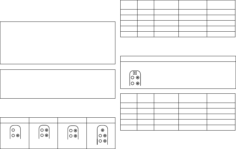
DF-1/IS-1
The labeling on each device provides information pertaining to the connector port
assignment in the header.
DF-1/IS-1/IS4
The labeling on each device provides information pertaining to the connector port
assignment in the header.
VR VR DX DR HF
DF-1
RV
SVC
DF-1
IS-1
RV
DF-1
RV
SVC
DF-1 IS-1
RA
IS-1
RV
DF-1
RV
SVC
DF-1 IS-1
RA
IS-1
RV
DF-1
RV
SVC
DF-1 IS-1
RA
IS-1
RV
LV
IS-1
Connector
port Lead
connector Configuration Implantation site Device type
RA IS-1 Bipolar Atrium VR DX, DR, HF
RV IS-1 bipolar Right ventricle VR, VR DX, DR, HF
RV DF-1 Shock coil Right ventricle VR, VR DX, DR, HF
SVC DF-1 Shock coil Superior vena cava VR, VR DX, DR, HF
LV IS-1 Unipolar, bipolar Left ventricle HF
HF QP
Connector
port Lead
connector Configuration Implantation site Device type
RA IS-1 Bipolar Atrium HF QP
RV IS-1 Bipolar Right ventricle HF QP
RV DF-1 Shock coil Right ventricle HF QP
SVC DF-1 Shock coil Superior vena cava HF QP
LV IS4 Unipolar, bipolar Left ventricle HF QP
IS4-LLLL
LV
IS-1
RA
IS-1
RV
DF-1
SVC
DF-1
RV
417634--B_GA_Intica-ProMRI_mul.fm Page 3 Friday, November 6, 2015 8:13 PM
4
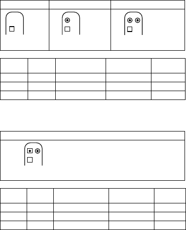
DF4/IS-1
The labeling on each device provides information pertaining to the connector port
assignment in the header.
DF4/IS-1/IS4
The labeling on each device provides information pertaining to the connector port
assignment in the header.
Leads
BIOTRONIK leads are sheathed with biocompatible silicone. They can be flexibly
maneuvered, are stable long-term, and are equipped for active or passive fixation. They
are implanted using a lead introducer set. Some leads are coated with polyurethane
which is known to increase the sliding properties for the lead. Leads with steroids
reduce inflammatory processes. The fractal design of the electrodes provides for low
pacing thresholds. BIOTRONIK provides adapters to connect already implanted leads to
new devices.
Telemetry
Telemetric communication between the device and the programmer can be carried out
following initialization either by applying the programming head (PGH) to the device or
by using wireless radio frequency (RF) telemetry in the programmer. BIOTRONIK calls
this function SafeSync.
Programmer
Implantation and follow-up are performed with BIOTRONIK's portable programmer:
Software PSW as of version 1505.
There are programmers with integrated or external SafeSync Module for RF telemetry.
Leadless ECG, IEGM, markers and functions are displayed simultaneously on the color
display.
The programmer allows you to determine the thresholds and to perform all tests
during an in-office follow-up; in addition, you can change the permanent program and
send it to the implanted device.
In addition to this, the programmer is used to set mode and parameter combinations,
as well as for interrogation and saving of data from the device.
VR DR HF
Connector
port Lead
connector Configuration Implantation site Device type
RA IS-1 Bipolar Atrium DR, HF
RV DF4 Bipolar and shock coil Right ventricle VR, DR, HF
LV IS-1 Unipolar, bipolar Left ventricle HF
HF QP
Connector
port Lead
connector Configuration Implantation site Device type
RA IS-1 Bipolar Atrium HF QP
RV DF4 Bipolar and shock coil Right ventricle HF QP
LV IS4 Unipolar, bipolar Left ventricle HF QP
DF4-LLHH
RV
DF4-LLHH
RV
RA
IS-1
DF4-LLHH
RV
RA
IS-1
LV
IS-1
DF4-LLHH
RV
LV
IS4-LLLL IS-1
RA
417634--B_GA_Intica-ProMRI_mul.fm Page 4 Friday, November 6, 2015 8:13 PM

Note:
Not all functions and parameters mentioned in this technical manual are
featured by each device type of each device family.
en • English
5
Modes
The mode setting depends on the individual diagnosis:
NBD and NBG codes
VVE is the NBD code for the antitachycardia mode of the single-chamber, dual-
chamber, and triple-chamber devices without atrial therapy:
VDE is the NBD code for the antitachycardia mode of the dual-chamber and triple-
chamber devices with atrial therapy:
DDDR is the NBG code for the antibradycardia mode of the dual-chamber devices:
DDDRV is the NBG code for the antibradycardia mode of the triple-chamber devices:
VDDR is the NBG code for the antibradycardia mode of the single-chamber type DX
device:
VVIR is the NBG code for the antibradycardia pacing modes of the single-chamber
device:
Device type Modes
VR VVI; VVIR; VOO; OFF
7 series: VVI-CLS
VR DX VDD; VDDR; VDI; VDIR; VVI; VVIR; V00; OFF
7 series: VVI-CLS
DR, HF (QP) DDD; DDDR; DDI; DDIR
DDDR-ADIR; DDD-ADI
VDD; VDDR; VDI; VDIR
VVI; VVIR; AAI; AAIR; VOO; DOO; OFF
7 series: VVI-CLS; DDD-CLS
V Shock in the ventricle
V Antitachycardia pacing (ATP) in the ventricle
E Detection via IEGM analysis
V Shock in the ventricle
D Antitachycardia pacing (ATP) in the atrium and ventricle
E Detection via IEGM analysis
D Pacing in the atrium and ventricle
D Sensing in the atrium and ventricle
D Pulse inhibition and pulse triggering
R Rate adaptation
D Pacing in the atrium and ventricle
D Sensing in the atrium and ventricle
D Pulse inhibition and pulse triggering
R Rate adaptation
V Multisite pacing in both ventricles
V Ventricular pacing
D Sensing in the atrium and ventricle
D Pulse inhibition and pulse triggering
R Rate adaptation
V Ventricular pacing
V Sensing in the ventricle
I Pulse inhibition in the ventricle
R Rate adaptation
417634--B_GA_Intica-ProMRI_mul.fm Page 5 Friday, November 6, 2015 8:13 PM

6
BIOTRONIK Home Monitoring
®
In addition to effective pacing therapy, BIOTRONIK provides a complete therapy
management system:
•
With Home Monitoring, diagnostic and therapeutic information as well as technical
data are automatically sent to a stationary or mobile transmitter via an antenna in
the device header. The data are encrypted and sent from the transmitter to the
BIOTRONIK Service Center via the cellular phone network.
•
The received data are deciphered and evaluated. Each physician can set the criteria
for evaluation to be used for each patient and can configure the time of notification
via e-mail, SMS or fax.
•
A clear overview of the results of this analysis is displayed for the attending physi-
cians on the protected Internet platform Home Monitoring Service Center (HMSC).
•
Data transmission from the device is performed with a daily device message.
•
Device messages which indicate special events in the heart or in the device are
forwarded immediately.
•
A test message can be initiated at any time using the programmer to immediately
check the Home Monitoring function.
Intica order numbers
Not all device types are available in every country:
Package contents
The storage package includes the following:
•
Sterile packaging with device
•
Serial number label
•
Patient ID card
•
Warranty booklet
Note:
The technical manual pertaining to the device is either included in hard copy
form in the storage package or in digital form on the internet.
The sterile container includes the following:
•
Device, blind plugs (if applicable)
•
Screwdriver
Intica 5 ProMRI
DF-1/IS-1 DF4/IS-1 DF-1/IS4/IS-1 DF4/IS4/IS-1
VR-T 404689 404690 — —
VR-T DX 404688 — — —
DR-T 404686 404687 — —
HF-T 404683 404684 — —
HF-T QP — — 406932 404685
Intica 7 ProMRI
DF-1/IS-1 DF4/IS-1 DF-1/IS4/IS-1 DF4/IS4/IS-1
VR-T 404634 404635 — —
VR-T DX 404633 — — —
DR-T 404631 404632 — —
HF-T 404627 404628 — —
HF-T QP — — 404629 404630
417634--B_GA_Intica-ProMRI_mul.fm Page 6 Friday, November 6, 2015 8:13 PM
en • English
7
Therapeutic and Diagnostic Functions
Diagnostic functions
•
Data from implantation and the most recent interrogations and follow-ups are
recorded as well as arrhythmia episodes; they are stored together with other data
to assess both the patients' and the device's state at any time.
•
To check the lead for proper functioning, an automatic impedance measurement
using subthreshold pacing pulses is performed in the device.
•
Leadless ECG function: For all device types, far-field derivation can be measured
without external leads between the right ventricular shock coil and housing, which,
depending on the implantation site, corresponds to ECG derivation II or III
(Einthoven).
•
Once a telemetry connection has been established during a test procedure in
an in-office follow-up, the leadless ECG and the IEGM are displayed with markers.
Antitachycardia pacing
•
The ICD can treat ventricular tachycardia with antitachycardia pacing (ATP); ATP
can also be delivered in the VF zone (ATP One Shot) when the stability criterion
(monomorphic rapid VTs) is met before shock delivery.
•
The ICD can also respond to atrial tachycardia with antitachycardia pacing (ATP) in
case of stable heart rates or with high-rate pacing (HF bursts) in case of unstable
heart rates.
•
Depending on the device type, the device program contains not only the ICD
functions but also all pacemaker functions for 1, 2 or 3 chambers. The heart rhythm
is continuously monitored; each arrhythmia is classified according to the heart rate
and the adjustable detection criteria. Depending on the preset values, antibrady-
cardia as well as antitachycardia therapy is inhibited or delivered.
Cardioversion, defibrillation
•
The ICD can treat ventricular tachyarrhythmia with cardioversion and/or defibrilla-
tion. Shock polarity and energy can be programmed individually. Shock energies
between 2.0 J and 40 J are possible. Before delivery of the shock, the ICD can be set
to only deliver a shock when ongoing tachyarrhythmia is confirmed; during this
time period the device can identify spontaneous conversion of the tachyarrhythmia
and cancel the charging process if necessary.
•
The shock paths can be set between the different shock coils (SVC/RV) and/or the
housing.
Antibradycardia pacing and CRT
•
Rate hystereses, automatic sensor functions, and a night program promote the
patient's intrinsic rhythm, avoid overdrive pacing, and facilitate adaptation of the
device to the individual needs of the patient.
•
Both atrial and ventricular thresholds are determined automatically in the device.
For the 5 and 7 series , capture control is used to set the pulse amplitudes so that
pacing is performed with the optimum atrial and ventricular amplitude for the
patients with each change of the pacing threshold.
•
Setting an upper tracking rate for the atrium prevents unspecific atrial pacing, thus
reducing the risk of pacemaker-mediated tachycardia.
•
Positive AV hysteresis functions support intrinsic conduction and thus the natural
contraction sequence. Negative AV hysteresis functions support the cardiac resyn-
chronization therapy by maintaining pacing in stress situations.
•
For resynchronization of the ventricles, triple-chamber implants have functions for
multisite pacing with possible VV delays in either direction.
•
To ensure that no additional surgery is necessary in case of a left-sided increase of
pacing threshold or undesired phrenic nerve stimulation, different pacing polarities
can be set for the left ventricular lead with a triple-chamber device. Up to
12 vectors can be used with the HF QP device type.
•
With the HF QP device of the 7 series: Two stimuli can be configured for the left
ventricle with a view to improve the resonchronization of the ventricles. The stimuli
can be delivered sequentially or simultaneously.
•
Additional, special form of rate adaptation with devices from the 7 series: an
increased cardiac output requirement is detected using physiological impedance
measurement. The measuring principle is based on contractile changes (ionotropy)
of the myocardium (CLS function: Closed Loop Stimulation). Rate adaptation is
automatically initialized and optimized in CLS mode.
•
Ventricular pacing suppression with devices from the 5 and 7 series unnecessary
ventricular pacing is avoided by promoting intrinsic conduction (Vp suppression
function). The device can thereby adapt to conduction changes and switch between
an ADI(R) and a DDD(R) mode.
417634--B_GA_Intica-ProMRI_mul.fm Page 7 Friday, November 6, 2015 8:13 PM
8
Storing programs
There are different therapy programs:
•
Parameter settings effective for the most common indications in pre-configured
programs (Program Consult).
•
For special indications, individual parameter settings can be stored in up to three
therapy programs.
ProMRI devices recognize magnetic resonance imaging devices
Intica has a sensor which can reliably recognize a magnetic resonance imaging device.
This sensor can be activated for a maximum of 14 days using the MRI AutoDetect
function during an interrogation.
If the patient comes near a magnetic resonance imaging device within the time set, the
implanted device recognizes the imaging device and automatically activates the preset
MRI program. Reprogrammation to the permanent program occurs also automatically
when the imaging device is left.
Home Monitoring functions
•
The device automatically sends information to the transmitter once a day. It also
sends messages related to events, which are immediately forwarded to the Service
Center. In addition to this, test messages can be initiated using the programmer.
•
Appointments for Home Monitoring-supported follow-ups can be scheduled via the
HMSC.
•
Important medical information in the device messages include the following:
—
Atrial and ventricular arrhythmias
—
Parameters relevant to leads in the atrium and ventricle: pacing thresholds,
sensing amplitudes, impedances
—
Current statistics
—
IEGM online HD with up to 3 high definition channels
2 General Safety Instructions
Operating Conditions
Technical manuals
The following technical manuals provide information about usage of the device
systems:
— Technical manual for the device
— Technical manual for the HMSC
— Technical manuals for leads
— Technical manuals for the programmer and its accessories
— Technical manuals for the user interface
— Technical manuals for cables, adapters and accessories
•
Technical manuals are either included in hard copy form in the storage package or
in digital form on the internet: manuals.biotronik.com.
•
Follow all relevant technical manuals.
•
Reserve technical manuals for later use.
Care during shipping and storage
•
Devices must not be stored or transported close to magnets or sources of electro-
magnetic interference.
•
Note the effects of the storage duration; see Battery Data.
Delivery in shipment mode
The device is delivered in shipment mode to protect the battery; capacitor reforming
required during storage could result in controlled extended charge times of the shock
capacitors.
•
The shipment mode is displayed on the programmer after the initial interrogation
(it is deactivated during implantation by the first valid (in-range) measurement of
the pacing impedance).
Temperature
Extremely low and high temperatures affect the service time of the battery in the
device.
•
Permitted for shipping and storage are +5°C to +45°C.
417634--B_GA_Intica-ProMRI_mul.fm Page 8 Friday, November 6, 2015 8:13 PM
en • English
9
Sterile delivery
The device and the screwdriver have been gas-sterilized. Sterility is guaranteed only if
the blister and quality control seal have not been damaged.
Sterile packaging
The device and screwdriver are packaged in two separately sealed blisters. The inner
blister is also sterile on the outside so that it can be transferred in a sterile state during
implantation.
Single use only
The device and screwdriver are intended for single use only.
•
Do not use the device if the package is damaged.
•
The device must not be resterilized and reused.
Possible Complications
General information on medical complications
Complications for patients and device systems generally recognized among practitio-
ners also apply to BIOTRONIK devices.
•
Normal complications may include fluid accumulation within the device pocket,
infections, or tissue reactions. Primary sources of complication information include
current scientific and technological knowledge.
•
It is impossible to guarantee the efficacy of antitachycardia therapy, even if the
programs have proven successful during tests or subsequent electrophysiological
examinations. In rare cases the set parameters may become ineffective. It is
possible for therapies to induce or accelerate tachycardia and cause sustained
ventricular flutter or fibrillation.
Skeletal myopotentials
Bipolar sensing and control of sensitivity are adapted by the device to the rate range of
intrinsic events so that skeletal myopotentials are usually not recorded. Skeletal
myopotentials can nonetheless be classified as intrinsic events especially at very high
sensing sensitivity and, depending on the interference, may cause inhibition or anti-
arrhythmia therapy.
In the case of undesired myopotentials, the device switches to asynchronous pacing if
the interference rate is exceeded.
Possible technical failures
Technical failure of a device system cannot be entirely ruled out. Possible causes can
include the following:
•
Lead dislodgement, lead fracture
•
Insulation defects
•
Device component failures
•
Battery depletion
•
Interrupted telemetry
Electromagnetic interference (EMI)
Any device can be sensitive to interference if external signals are sensed as intrinsic
rhythm or if measurements prevent rate adaptation.
•
BIOTRONIK devices have been designed so that their susceptibility to EMI is
minimal.
•
Due to the intensity and variety of EMI, there is no guarantee for safety. It is
generally assumed that EMI produces only minor symptoms, if any, in patients.
•
Depending on the pacing mode and the type of interference, sources of interference
may lead to pulse inhibition or triggering, an increase in the sensor-dependent
pacing rate or asynchronous pacing.
•
Under unfavorable conditions, for example during therapeutic or diagnostic proce-
dures, interference sources may induce such a high level of energy into the pacing
system that the cardiac tissue surrounding the lead tip is damaged.
Device behavior in case of EMI
In case of electromagnetic interference, the device switches to asynchronous pacing
for as long as the interference rate is exceeded.
Static magnetic fields
The magnetic sensor in the device detects magnetic fields starting at a magnetic flux
density of approximately 1.5 mT. Magnetic fields below 1 mT do not affect the sensor.
417634--B_GA_Intica-ProMRI_mul.fm Page 9 Friday, November 6, 2015 8:13 PM

10
Possible Risks
Procedures to avoid
The following procedures must be avoided, as they may cause harm to the patient or
damage the device and, as a result, put the system functionality at risk:
•
Transcutaneous electrical nerve stimulation
•
Hyperbaric oxygen therapy
•
Applied pressures higher than normal pressure
Risky therapeutic and diagnostic procedures
If electrical current from an external source is conducted through the body for diag-
nostic or therapeutic purposes, then the device can be subjected to interference, which
can place the patient at risk.
Arrhythmia or ventricular fibrillation can be induced during diathermic procedures
such as electrocautery, HF ablation or HF surgery. For example, damaging pressure
levels may arise during lithotripsy. For example, excessive warming of body tissue near
the device system may occur during therapeutic ultrasound. Influences on the device
are not always immediately clear.
If risky procedures cannot be avoided, the following should be observed at all times:
•
Electrically insulate the patient.
•
Switch off the ICD's detection function; the pacemaker function may remain active,
switch to asynchronous modes if necessary.
•
Do not introduce energy near the device system.
•
Additionally check the peripheral pulse of the patient.
•
Monitor the patient during and after every intervention.
External defibrillation
The device is protected against the energy that is normally induced by external defibril-
lation. Nevertheless, any implanted device may be damaged by external defibrillation.
Specifically, the current induced in the implanted leads may result in necrotic tissue
formation close to the electrode/tissue interface. As a result, sensing properties and
pacing thresholds may change.
•
Place adhesive electrodes anterior-posterior or perpendicular to the axis formed
by the device to the heart at least 10 cm away from the device and from implanted
leads.
Radiation therapy
The use of radiation therapy must be avoided due to possible damage to the device and
the resulting impaired functional safety. If this type of therapy is to be used anyway,
prior risk/benefit analysis is absolutely necessary. The complexity of influencing
factors such as different sources of radiation, a variety of devices and therapy condi-
tions makes it impossible to issue directives that guarantee radiation therapy without
an impact on the device. The EN 45502 standard pertaining to active implantable
medical devices requires the following measures during the administration of thera-
peutic ionizing radiation:
•
Adhere to instructions for risky therapy and diagnosis procedures.
•
Shield device against radiation.
•
After applying radiation, double-check the device system to make sure it is func-
tioning properly.
Note:
Please contact BIOTRONIK with questions during the risk/benefit analysis.
Magnetic resonance imaging
Magnetic resonance imaging must be avoided due to the associated high frequency
fields and magnetic flux density: Damage or destruction of the device system by strong
magnetic interaction and damage to the patient by excessive warming of the body
tissue in the area surrounding the device system.
Under certain conditions and when maintaining mandatory measures to protect the
patient and device system, magnetic resonance imaging can be performed. BIOTRONIK
devices with the "MR conditional" function bear the identification ProMRI.
•
The ProMRI
®
manual – MR conditional device systems – contains detailed informa-
tion on safely conducting an MR scan.
—
Download the digital manual from the web site:
manuals.biotronik.com
—
Order the printed manual from BIOTRONIK.
•
Does approval as "MR-Conditional" apply in your country or region?
Request current information from BIOTRONIK.
417634--B_GA_Intica-ProMRI_mul.fm Page 10 Friday, November 6, 2015 8:13 PM

en • English
11
3 Implantation
Implantation Procedure
Having parts ready
The following parts that correspond to the requirements of the EC Directive 90/385/EEC
are required:
•
BIOTRONIK device with blind plug and screwdriver
•
BIOTRONIK leads and lead introducer set
—
Single-chamber device: one bipolar ICD lead with 1 or 2 shock coils for the
ventricle
—
Dual-chamber device: one bipolar lead for the atrium and one bipolar ICD lead
for the ventricle with 1 or 2 shock coils
—
Triple-chamber device: an additional unipolar or bipolar or quadripolar LV lead
•
The lead connections DF-1, DF4 as well as IS-1 and IS4 are permitted. Use only
adapters approved by BIOTRONIK for leads with different lead connections or leads
from other manufacturers.
•
BIOTRONIK programmer (with integrated SafeSync RF telemetry or with separate
SafeSync Module) and approved cables
•
External multi-channel ECG device
•
Keep spare parts for all sterile components.
Keeping an external defibrillator ready
To be able to respond to unforeseeable emergencies or possible technical failures of
the device:
•
Keep an external defibrillator and paddles or patch electrodes ready.
Inadequate therapy due to defective device
If an unpacked device is dropped on a hard surface during handling, electronic parts
could be damaged.
•
Use a replacement device.
•
Return the damaged device to BIOTRONIK.
Unpacking the device
•
Peel the sealing paper off of the outer blister at the marked position in the direction
indicated by the arrow. The inner blister must not come into contact with persons
who have not sterilized their hands or gloves, nor with non-sterile instruments!
•
Take hold of the inner blister by the gripping tab and take it out of the outer blister.
•
Peel the sealing paper off of the sterile inner blister at the marked position in the
direction indicated by the arrow.
Checking parts
Damage to any of the parts can result in complications or technical failures.
•
Check for damage before and after unpacking all parts.
•
Replace damaged parts.
•
Upon delivery, the tachyarrhythmia therapy function in the ICD is deactivated.
The ICD must only be implanted in this state.
•
Leads must not be shortened.
Implantation site
•
Depending on lead configuration and the patient's anatomy, the ICD is generally
implanted subpectorally on the left side.
Preventing leakage currents
Leakage currents between the tools and the device must be prevented during implanta-
tion.
•
Electrically insulate the patient.
W
WARNING
417634--B_GA_Intica-ProMRI_mul.fm Page 11 Friday, November 6, 2015 8:13 PM

Shock delivery with activated ICD
There is a risk of unintended shock delivery when handling an activated ICD.
•
Deactivate ICD therapy before touching the device during implantation, device
replacement and explantation.
12
Preventing unintentional shock delivery
Avoiding damage to the header
Set screws and blind plugs (if applicable) must be tightened or loosened with care.
•
Loosen set screws with the supplied screwdriver. Use only BIOTRONIK screw-
drivers with torque control!
•
Do not forcibly pull out the blind plug!
•
If lead revision is necessary, re-order sterile screwdrivers from BIOTRONIK.
Short circuit due to open lead connector ports
Connector ports in the header which are open and thus not electrolyte-proof may
cause undesired current flows to the body and penetration of body fluid into the
device.
•
Close unused connector ports with blind plugs.
Preventing short circuits in the header
Ensure that connector ports are clean
In case of contamination during implantation:
•
Clean lead connectors with a sterile cloth.
•
Rinse connector port only with sterile water.
Overview: Implanting
Connecting the device
The lead connectors are connected to the ports in the header of the device:
W
WARNING
W
WARNING
1Prepare the vein.
2 Implant the leads, perform the measurements, and fixate the leads.
3 Form the device pocket.
4 Connect the lead connector to the device.
5 Insert the device.
6 Guide the fixation suture through the opening in the header and fixate the device
in the prepared device pocket.
7 Close the device pocket.
8 Check the device with standard tests.
1 Remove stylets and stylet guides.
2 Connect lead for defibrillation: DF-1/IS-1 or DF-1/IS4/IS-1
•
Connect the DF-1 connector for the right-ventricular shock coil to RV.
•
Connect the DF-1 connector for the supraventricular shock coil to SVC.
(Or connect a subcutaneous array to SVC).
Connect lead for defibrillation (and sensing/pacing): DF4/IS-1 or DF4/IS4/IS-1
•
Connect the DF4 connector to RV.
3 Connect lead for sensing/pacing: DF-1/IS-1 or DF-1/IS4/IS-1
•
Connect the bipolar IS-1 connector for the atrium to RA.
•
Connect the bipolar IS-1 connector for the right ventricle to RV.
•
Connect the unipolar or bipolar IS-1 connector for the left ventricle or the
quadripolar IS4 connector for the left ventricle to LV.
Connect lead for sensing/pacing: DF4/IS-1 or DF4/IS4/IS-1
•
Connect the bipolar IS-1 connector for the atrium to RA.
•
Connect the unipolar or bipolar IS-1 connector for the left ventricle or the
quadripolar IS4 connector for the left ventricle to LV.
417634--B_GA_Intica-ProMRI_mul.fm Page 12 Friday, November 6, 2015 8:13 PM
Inadequate therapy
When leads are not spaced sufficiently apart or are positioned inappropriately, this
can lead to far-field sensing or insufficient defibrillation.
•
The distance between 2 shock coils must be greater than 6 cm.
•
Tip and ring electrodes must not have contact with each other.
en • English
13
Keeping distance between leads
Applying the programming head
The programming head (PGH) features a diagram of the device. This is used to assist in
positioning the head to ensure proper telemetry.
•
Make sure the PGH is positioned correctly.
Establishing RF telemetry
The programmer (or the SafeSync Module) can be no more than 3 m from the device;
ideally there should be no hindrances between the patient and the programmer.
•
Switch on RF telemetry on the programmer.
•
Apply the programming head for about 2 s until successful initialization is displayed
on the programmer:
The SafeSync symbol is displayed in the navigator and the signal
strength is displayed in the status line.
•
Remove the programming head.
Activating ICD therapy
•
Load the software that is suitable for the device type in the programmer.
•
Activate ICD therapy.
•
Shipment mode is permanently deactivated once the leads have been connected
and initial measurement of the pacing impedance has been performed success-
fully. The device data are saved.
•
Take precautionary measures while programming.
•
If the device induces tachycardia while programming ATPs or does not deliver
adequate therapy in the DFT test: use emergency shock or an external defibrillator.
Precautionary Measures while Programming
Performing standard tests and monitoring the patient
Critical conditions can occur for the patient even during standard tests due to inade-
quate parameter settings or interrupted telemetry.
•
Ensure sufficient patient care even during tests.
•
After the threshold test, check to determine whether the threshold is clinically and
technically justifiable.
•
Continuously monitor the ECG and the patient's condition.
•
Cancel testing if necessary.
4 Push the lead connector into the header without twisting or bending the
connector or conductor until the connector tip (on the DF-1 connector) or the
insertion indicator (on the DF4 and the IS4 connector) becomes visible behind
the set screw block. This indicator can vary depending on the manufacturer of
the lead used.
5 If you cannot easily plug the lead connector into the connection:
•
Use only sterile water as lubricant.
6 If the lead connector cannot be inserted completely, the set screw may be
protruding into the drill hole of the set screw block.
•
Use the screwdriver to perpendicularly pierce through the slitted point in
the center of the silicone plug until it reaches the set screw.
•
Carefully loosen the set screw without completely unscrewing it, so that it
does not become tilted upon retightening.
7 Turn the set screw clockwise until torque control starts (you will hear a clicking
sound).
8 Carefully withdraw the screwdriver without retracting the set screw.
•
In case of IS-1 connections with 2 set screws, tighten both screws!
•
When you withdraw the screwdriver, the silicone plug automatically seals
the access to the screw head safely.
W
WARNING
417634--B_GA_Intica-ProMRI_mul.fm Page 13 Friday, November 6, 2015 8:13 PM
14
Cancelling telemetry
Programmer interference or interrupted telemetry during performance of temporary
programs (follow-up tests) can result in inadequate pacing of the patient. This is the
case if the programmer can no longer be operated due to a program error or
a defective touch screen and therefore the temporary program cannot be terminated.
Under these circumstances, it is helpful to cancel telemetry, in which case the device
automatically switches to the permanent program.
•
In the case of telemetry with programming head: lift the PGH by at least 30 cm.
•
In the case of RF telemetry: switch off and reposition the programmer.
•
Turn off possible sources of interference.
Avoiding critical parameter settings
No modes and parameter combinations that pose a risk to the patient should be set.
•
Prior to setting rate adaptation, determine the patient's capacity for exertion.
•
Check compatibility and effectiveness of parameter combinations after making
settings.
•
When setting atrial therapies after an AT or AF has been detected, note that no
ventricular tachyarrhythmia can be detected for the duration of atrial therapy
delivery.
Avoiding risks in the case of exclusive LV pacing
Lead dislodgement in the case of exclusive left ventricular pacing could pose the
following risks: loss of ventricular pacing and ATP therapy, induction of atrial arrhyth-
mias.
•
Consider sensing and pacing parameters with reference to loss of therapy.
•
Exclusive LV pacing is not recommended for patients who depend on the device.
•
Please note that capture control is not available.
•
In the case of follow-ups and threshold tests, take loss of synchronized ventricular
pacing into consideration.
•
Mode switching and post shock do not permit exclusive LV pacing. Please note the
effects when programming mode switching and the post shock parameters.
Monitoring the patient when setting asynchronous modes
The asynchronous modes V00 and D00 can only be set if tachyarrhythmia sensing is
deactivated. This would leave the patient without sensing and therefore without ICD
therapy.
•
Continually monitor the patient.
•
Keep an external defibrillator ready.
Complying with the morphology criteria
To distinguish between ventricular and supraventricular tachyarrhythmia, QRS
complexes, among other aspects, are compared to each other. You can set
a MorphMatch threshold for the purpose of tachyarrhythmia discrimination, usually
a standard value. Settings that differ, that is to say, a higher or lower threshold to
discriminate the individual QRS complexes, may lead to a delayed/inhibited or unneces-
sary therapy.
•
Set deviations from the standard with particular caution.
Setting sensing
Manually set parameters can be unsafe. For example, unsuitable far-field protection
may impede sensing of intrinsic pulses.
•
Note automatic sensitivity control.
Preventing device-induced complications
BIOTRONIK devices feature several functions to prevent device-induced complications
to the greatest extent possible:
•
Measure the retrograde conduction time.
•
Set PMT protection.
•
Set the VA criterion.
Preventing conduction of atrial tachycardia
BIOTRONIK devices feature several functions to prevent conduction of atrial tachy-
cardia to the ventricle(s):
•
Set mode switching for indicated patients.
•
Set the upper rate and the refractory periods to prevent abrupt ventricular rate
switching.
•
Prefer Wenckebach response and avoid 2:1 behavior.
•
Set all parameters so as to prevent constant changing between atrial and
ventricular-controlled modes.
417634--B_GA_Intica-ProMRI_mul.fm Page 14 Friday, November 6, 2015 8:13 PM
en • English
15
Avoiding AV crosstalk
When pacing using atrial ATP parameters, atrial pacing pulses can either be conducted
into the ventricle or be sensed such that ventricular pacing is prevented.
•
Check the settings for the presence of crosstalk.
•
If necessary, temporarily set VVI and a rate for backup stimulation so that no
ventricular pulses are prevented.
Observing the shock impedance limit
The implanted device could be damaged if the shock impedance is too low.
•
The shock impedance must be > 25 Ω.
Preventing recurrence after therapy shock
After a therapy shock, pacing can be performed with a post-shock program if there is
no intrinsic rhythm.
•
The following post-shock program parameters can be adjusted: Post-shock
duration, basic rate, rate hysteresis, ventricular pacing, LV T-wave protection,
triggering, AV delay (fixed, not dynamic)
•
The default settings for the post-shock program are as follows:
A and RV: 7.5 V and 1.5 ms
LV: settings from the permanent program
Phrenic nerve stimulation that cannot be terminated
In rare cases, chronic phrenic nerve stimulation cannot be terminated by reprogram-
ming the available left ventricular pacing configuration or using other measures.
•
Set a right ventricular mode both in the permanent program as well as the ATP, in
the post-shock program and for mode switching if need be.
Note the reduced pulse amplitude due to a battery voltage drop
If the rate and amplitude are set very high and the pulse width is set too long at the
same time, the battery voltage may temporarily drop so low that the actual pulse
amplitude drops well below the selected level.
•
Continuously check the pacing efficiency using ECG monitoring.
Observe when inducing short-term cardiac arrest
To permit TAVI (transcatheter aortic valve implantation), the pressure in the heart must
be reduced so that the heart valve can be correctly positioned. Intentional cardiac
arrest by high-rate pacing (rapid pacing) should be brief, must be tolerated by the
patient and can trigger a life-threatening arrhythmia.
•
Take all necessary precautionary measures and keep required emergency
equipment ready.
•
Continually monitor the patient by ECG.
•
Complete the TAVI procedure before high-rate pacing ends. Extend the pacing
duration if necessary.
•
Abort the procedure if it is not successfully completed within the maximum pacing
duration so that cardiac arrest can be stopped.
•
Reactivate ICD therapy at a clinically indicated point in time when the TAVI process
is completed.
Checking the settings of the DX lead
The triple-chamber device allows for a DX lead to be implanted for the right atrium and
connected to the IS-1 connector of the device.
•
DX sensing in the atrium requires a special setting in the programmer which then
has to be transmitted.
Checking for electrodes suitable for the shock path
Three different shock paths can be set. Two of these form an electrical path to the
housing of the implanted device.
•
For the RV -> SVC shock path, a second shock coil must be available (dual shock
coil).
Recognizing lead failure
Automatic impedance measurement is always switched on.
•
Impedance values that indicate technical failure of a lead are documented in the
event list.
Permanent program Post-shock program
DDD(R), DDI(R), AAI(R), DDD-ADI(R)
7 series: DDD-CLS
DDI
VDD(R), VDI(R) VDI
VVI(R) and OFF
7 series: VVI-CLS
VVI
417634--B_GA_Intica-ProMRI_mul.fm Page 15 Friday, November 6, 2015 8:13 PM

16
Considering power consumption and service time
RF telemetry requires somewhat more power: Consumption during implantation corre-
sponds to approximately 7 days of service time and consumption during a 20-minute
follow-up corresponds to approximately 2 days.
•
Do not establish unnecessary RF telemetry.
•
After 5 minutes without input, SafeSync switches to the economy mode.
•
Check the battery capacity of the device at regular intervals.
Note:
Multi pole pacing also needs more power, which leads to various lengths of
service time.
Magnet Response
Application of the programming head when ICD therapy is set
If a connected programming head is applied and is communicating with the
programmer and ICD therapy is permanently set, detection and therapy remain intact
except during the diagnostic tests. If ICD therapy is not set as permanent, no therapy is
delivered when the programming head is applied.
Programming head application
When the programming head is applied, time remains for device interrogation and for
manual activation or deactivation of the therapy before the device switches back to the
previously set permanent therapy mode. The same applies to programming head appli-
cation to establish RF telemetry contact.
Application of a permanent magnet
Applying a permanent magnet interrupts detection and therapy of tachycardia events.
After 8 hours of this type of deactivation, the device automatically reactivates the
therapy functions to prevent accidental permanent deactivation.
•
If detection interruptions of longer than 8 hours are required, the magnet has to be
briefly removed from the device. The 8 hour countdown restarts when the magnet
is applied again.
•
Use BIOTRONIK magnets: type M-50 permanent magnets.
Follow-up
Follow-up intervals
Follow-ups must be performed at regular, agreed intervals.
•
The first follow-up should be carried out by the physician using the programmer
(in-office follow-up) approximately 3 months after implantation following the lead
ingrowth phase.
•
The next in-office follow-up should be carried out once a year and no later than
12 months after the last in-office follow-up.
Follow-up with BIOTRONIK Home Monitoring
Monitoring using the Home Monitoring function does not serve to replace regular in-
office appointments with the physician required for other medical reasons. Follow-up
supported by Home Monitoring can be used to functionally replace in-office follow-up
under the following conditions:
•
The patient was informed that the physician must be contacted despite use of the
Home Monitoring function if symptoms worsen or if new symptoms arise.
•
Device messages are transmitted regularly.
•
The physician decides whether the data transmitted via Home Monitoring with
regard to the patient's clinical condition as well as the technical state of the device
system are sufficient. If not, an in-office follow-up needs to be carried out.
Possible early detection due to information gained via Home Monitoring may necessi-
tate an additional in-office follow-up. For example, the data may indicate at an early
stage lead problems or a foreseeable end of service time (ERI). Furthermore, the data
could provide indications of previously unrecognized arrhythmias or modification of the
therapy by reprogramming the device.
417634--B_GA_Intica-ProMRI_mul.fm Page 16 Friday, November 6, 2015 8:13 PM
en • English
17
Follow-up with the programmer
Use the following procedure for in-office follow-up:
Patient Information
Patient ID card
A patient ID card is included in delivery.
•
Provide the patient with the patient ID.
•
Request that patients contact the physician in case of uncertainties.
Prohibitory signs
Premises with prohibitive signs must be avoided.
•
Draw the patient's attention to prohibitory signs.
Possible sources of interference
Electromagnetic interference should be avoided in daily activities. Sources of interfer-
ence should not be brought into close proximity with the device.
•
Draw the patient's attention to special household appliances, security checkpoints,
anti-theft alarm systems, strong electromagnetic fields, cell phones, and transmit-
ters among other things.
•
Request patients to do the following:
—
Use cell phones on the side of their body that is opposite of the device.
—
Keep the cell phone at least 15 cm away from the device both during use and
when stowing.
Replacement Indications
Possible battery levels
•
BOS: Beginning of Service: > 90% charge
•
MOS 1: Middle of Service: 90% to 40% residual charge
•
MOS 2: Middle of Service: < 40% residual charge
•
ERI: Elective Replacement Indication (i.e. RRT: Recommended Replacement Time)
•
EOS: End of Service
Temporally limited therapy
If ERI occurs shortly after follow-up and is only detected during the subsequent
follow-up, then the remaining service time can be much less than 3 months.
•
Replace device soon.
Elective Replacement Indication (ERI)
Elective Replacement Indication can be detected by Home Monitoring.
•
The device can monitor the heart rhythm for at least 3 more months.
•
At least 6 maximum energy shocks can be delivered until EOS occurs.
•
The set parameters in the device do not change.
Patient at risk of death
If EOS replacement indication occurs before replacement of the device, then the
patient is without therapy.
•
Replace device immediately.
•
Monitor patient constantly until immediate replacement of the device!
EOS replacement indication
End of Service can be detected by Home Monitoring.
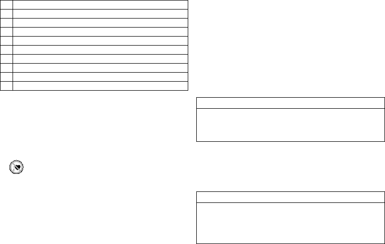
1 Record and evaluate the ECG.
2 Interrogate the device.
3 Evaluate the status and automatically measured follow-up data.
4 Check the sensing and pacing functions.
5 Possibly evaluate statistics and IEGM recordings.
6 Manually perform standard tests if necessary.
7 Possibly customize program functions and parameters.
8 Transmit the permanent program to the implanted device.
9 Print and document follow-up data (print report).
10 Finish the follow-up for this patient.
W
CAUTION
W
WARNING
417634--B_GA_Intica-ProMRI_mul.fm Page 17 Friday, November 6, 2015 8:13 PM

18
•
VT and VF detection and all therapies are deactivated!
•
The antibradycardia function remains active in the VVI mode:
—
Ventricular pacing: RV; basic rate 50 bpm; without special pacemaker functions
such as hysteresis, etc.
—
Pulse amplitude of 6 V; pulse width of 1.5 ms
—
Cycle duration for BIOTRONIK Home Monitoring: 90 days
Explantation and Device Replacement
Explantation
•
Interrogate the device status.
•
Deactivate VT and VF therapies prior to explantation.
•
Remove the leads from the header. Do not simply cut them loose.
•
Use state-of-the-art techniques to remove the device and, if necessary, the leads.
Note:
Normal oxidation processes may cause ICD housing discolorations. This is
neither a device defect nor does it influence device functionality.
•
Explants are biologically contaminated and must be disposed of safely due to risk of
infection.
Device replacement
If, upon replacing the device, already implanted leads are no longer used but left in the
patient, then an additional uncontrolled current path to the heart can result.
•
Deactivate VT and VF therapies prior to device replacement.
•
Cap unused lead connectors and plug unused connector ports.
Basic principles:
•
The device must not be resterilized and reused.
Cremation
Devices must not be cremated.
•
Explant the device before the cremation of a deceased patient.
Disposal
BIOTRONIK takes back used products for the purpose of environmentally safe disposal.
•
Clean the explant with a solution of at least 1% sodium hypochlorite.
•
Rinse off with water.
•
Fill out explantation form and send to BIOTRONIK together with the cleaned device.
4 Parameters
Bradycardia / CRT
General ICD therapy
Timing: Basic rate day/night and rate hystereses
Parameter Range of values Standard VR DX DR HF
ICD therapy OFF; ON ON xxxx
Programs Display standard program;
Display safe program;
Display first interrogated
program; Individual 1, 2, 3;
ProgramConsult
— xxxx
Parameter Range of values Standard VR DX DR HF
Basic rate 30 ... (5) ... 100 ... (10)
... 160 bpm
40 bpm x x
60 bpm x x
Night rate OFF; 30 ... (5) ... 100 bpm OFF xxxx
Night begins 00:00 ... (00:01)
... 23:59 hh:mm
22:00
hh:mm
xxxx
Night ends 06:00
hh:mm
Rate hysteresis OFF; -5 ... (-5) ... -25 ...
(-20) ... -65 bpm
OFF xxxx
Scan/repetitive OFF; ON ON xxxx
417634--B_GA_Intica-ProMRI_mul.fm Page 18 Friday, November 6, 2015 8:13 PM

en • English
19
Timing: AV delay
Timing: Post-shock pacing
Timing: Upper rate
Timing: Mode switching
Timing: Ventricular pacing suppression
Parameter Range of values Standard VR DX DR HF
AV dynamics Low; Medium; High; Fixed;
(Individual)
Low xxx
AV delay (1 or 2) after:
– Pacing 40 ... (5) ... 350 ms
Only for Fixed, also: 15
–xx
– Sensing Either automatic: AV delay
after pacing + sense
compensation
Or: 15; 40 ... (5) ... 350 ms
– xxx
– At rate 1 50 ... (10) ... 130 bpm 60 bpm
– At rate 2 60 ... (10) ... 140 bpm 130 bpm
Sense compensation OFF; -5 ... (-5) ... -120 ms -40 ms x x
AV hysteresis mode OFF; Positive; Negative;
IRSplus
OFF x x
OFF; Positive; Negative OFF x
AV hysteresis (positive) 70; 110; 150; 200 ms 70 ms x x x
7 series, CLS modes:
AV hysteresis (positive)
70; 110; 150 ms 110 ms x x x
AV hysteresis (negative) 10 ... (10) ... 150 ms 50 ms x x x
AV scan and repetitive
(positive)
OFF; ON ON x x x
Parameter Range of values Standard VR DX DR HF
Post-shock duration OFF; 10 s; 30 s; 1 min;
2 min; 5 min; 10 min
10 s xxxx
Post-shock basic rate 30 ... (5) ... 100 ... (10)
... 160 bpm
60 bpm xxxx
AV delay post shock 50 ... (10) ... 350 ms 140 ms x x
Ventricular post-shock
pacing
RV; BiV RV x
Parameter Range of values Standard VR DX DR HF
Upper rate 90 ... (10) ... 160 bpm 130 bpm x x x
Atrial upper rate OFF; 175; 200; 240 bpm 200 bpm x x
Parameter Range of values Standard VR DX DR HF
Intervention rate OFF; 120 ... (10) ... 200 bpm 160 bpm x x x
Onset criterion 3 ... (1) ... 8 (out of 8) 5 x x x
Resolution criterion
Modification of basic rate OFF; 5 ... (5) ... 30 bpm 10 bpm x x x
Mode After mode VDD(R): VDI(R) VDIR x x x
After mode DDD(R),
DDD-ADI(R): DDI(R)
7 series, after mode DDD-
CLS: DDI(R)
DDIR x x
After mode switching:
– Rate OFF; 5 ... (5) ... 50 bpm 10 bpm x x x
– Duration 1 ... (1) ... 30 min 1 min
Rate stabilization with
mode switching
7 series: ON; OFF OFF x x x
Parameter Range of values Standard VR DX DR HF
Vp suppression OFF; ON OFF x x
Pacing suppression
after consecutive Vs
1 ... (1) ... 8 6 x x
Pacing support after
X-out-of-8 cycles
1; 2; 3; 4 3 x x
417634--B_GA_Intica-ProMRI_mul.fm Page 19 Friday, November 6, 2015 8:13 PM

20
Timing: Ventricular pacing
Timing: Ventricular multi pole pacing
The following parameters apply for devices of the 7 series, HF QP type:
Timing: Refractory periods and blanking periods
Timing: PMT protection
Timing: Rate adaptation via accelerometer
Parameter Range of values Standard VR DX DR HF
Permanent RV; BiV; LV BiV x
Triggering OFF; RVs; RVs+PVC RVs x
LV T-wave protection OFF; ON ON x
Maximum trigger rate:
– DDD(R) and VDD(R) UTR + 20; 90 ... (10)
... 160 bpm
UTR + 20 x
– DDI(R), VDI(R) and VVI(R) 90 ... (10) ... 160 bpm 130 bpm
Initially paced chamber RV; LV LV x
VV delay after Vp 0 ... (5) ... 100 ms 0 ms x
Parameter Range of values Standard HF QP
Pacing polarity 2nd LV OFF;
LV1 tip -> LV2 ring
LV1 tip -> LV4 ring
LV1 tip -> RV coil
LV1 tip -> housing
LV2 ring -> LV1 tip
LV2 ring -> LV4 ring
LV2 ring -> RV coil
LV3 ring -> LV2 ring
LV3 ring -> LV4 ring
LV3 ring -> RV coil
LV4 ring -> LV2 ring
LV4 ring -> RV coil
OFF x
LV-LV delay 0 ... (5) ... 50 ms 0 ms x
Pulse amplitude LV 2nd LV 0.5 ... (0.25) ... 4.0 ... (0.5)
... 6.0; 7.5 V
2.5 V x
Pulse width LV 2nd LV 0.4; 0.5 ... (0.25) ... 1.5 ms 0.4 ms x
Parameter Range of values Standard VR DX DR HF
PVARP AUTO; 175 ... (25) ... 600 ms 225 ms x x x
PVARP extension OFF; ON ON x x x
Blanking RV after atrial
pacing
40 ... (10) ... 100 ms 50 ms x x
LV blanking after
RV pacing
50 ... (10) ... 100 ms 80 ms x
RV blanking after
LV pacing
Far-field protection
after Vs
OFF; 25 ... (25) ... 225 ms 75 ms x x x
Far-field protection
after Vp
50 ... (25) ... 225 ms 75 ms x x x
Parameter Range of values Standard VR DX DR HF
PMT detection/termination OFF; ON ON x x x
VA criterion 250 ... (10) ... 500 ms 350 ms x x x
Parameter Range of values Standard VR DX DR HF
Maximum sensor rate 80 ... (10) ... 160 bpm 120 bpm xxxx
Sensor gain AUTO; Very low; Low;
Medium; High; Very high
Mediumxxxx
Sensor threshold Very low; Low; Medium;
High; Very high
Mediumxxxx
Rate increase 1; 2; 4; 8 bpm/cycle 2 bpm/
cycle
xxxx
Rate decrease 0.1; 0.2; 0.5; 1.0 bpm/cycle 0.5 bpm/
cycle
xxxx
Rate fading OFF; ON OFF xxxx
417634--B_GA_Intica-ProMRI_mul.fm Page 20 Friday, November 6, 2015 8:13 PM

en • English
21
Timing: Rate adaptation via CLS
The following parameters apply to devices of series 7:
Pacing: Pulse amplitude and pulse width
Pacing: Atrial capture control
Pacing: Ventricular capture control
Lead configuration LV on IS-1 connection
Parameter Range of values Standard VR DX DR HF
Maximum sensor rate 80 ... (10) ... 160 bpm 120 bpm xxxx
CLS response Very low; Low; Medium;
High; Very high
Mediumxxxx
CLS resting rate control OFF; +10 ... (+10) ...
+50 bpm
+20 bpmxxxx
Vp required Yes; No No x x x
Yes Yes x
Parameter Range of values Standard VR DX DR HF
Pulse amplitude A 0.5 ... (0.25) ... 4.0 ... (0.5)
... 6.0; 7.5 V
AUTO x x
Pulse amplitude V/RV xxxx
Pulse amplitude LV x
Pulse width A 0.4; 0.5 ... (0.25) ... 1.5 ms 0.4 ms x x
Pulse width V/RV xxxx
Pulse width LV x
Parameter Range of values Standard VR DX DR HF
Atrial capture control OFF; ATM; ON ON x x
Threshold test start with ATT: 2.5 ... (0.5)
... 5.0 V
with ATM: 3.5 V
3.5 V x x
Minimum amplitude 0.5 ... (0.25) ... 4.0 V 1.0 V x x
Safety margin 0.5; 1.0; 1.2 V 1.0 V x x
Parameter Range of values Standard VR DX DR HF
Ventricular capture
control RV + LV
OFF; ATM; ON ON xxxx
Threshold test start with ATT: 2.5 ... (0.5)
... 5.0 V
with ATM: 3.5 V
3.5 V xxxx
Minimum amplitude 1.0 ... (0.25) ... 4.0 V 1.0 V xxxx
Safety margin 1.0; 1.2 V 1.0 V xxxx
Parameter Range of values Standard VR DX DR HF
Pacing polarity LV
(IS-1)
LV tip -> LV ring
LV tip -> RV coil
LV ring -> LV tip
LV ring -> RV coil
UNIP
LV tip -> RV
coil
x
Sensing polarity LV
(IS-1)
UNIP; BIPL UNIP x
417634--B_GA_Intica-ProMRI_mul.fm Page 21 Friday, November 6, 2015 8:13 PM

22
Lead configuration LV on IS4 connection
MRI program
MRI program
Parameter Range of values Standard HF QP
Pacing polarity LV
(IS4)
LV1 tip -> LV2 ring
LV1 tip -> LV4 ring
LV1 tip -> RV coil
LV1 tip -> housing
LV2 ring -> LV1 tip
LV2 ring -> LV4 ring
LV2 ring -> RV coil
LV3 ring -> LV2 ring
LV3 ring -> LV4 ring
LV3 ring -> RV coil
LV4 ring -> LV2 ring
LV4 ring -> RV coil
LV1 tip -> LV2
ring
x
Sensing polarity LV
(IS4)
LV1 tip -> LV2 ring
LV1 tip -> housing
LV2 ring -> LV3 ring
LV2 ring -> housing
LV3 ring -> LV4 ring
LV3 ring -> housing
LV4 ring -> housing
LV1 tip -> LV2
ring
x
Parameter Range of values Standard VR DX DR HF
MRI program OFF; AUTO; ON OFF xxxx
Expiration date Today ... (1) ... Today
+ 14 days
Today
+ 14 days
xxxx
Mode VOO; OFF OFF x x
VOO; DOO; OFF x
V00; V00-BiV; D00;
D00-BiV; OFF
x
Basic rate 70 ... (5) ... 100 ... (10)
... 160 bpm
90 bpm xxxx
Pulse amplitude LV 0.5 ... (0.25) ... 4.0 ... (0.5)
... 6.0; 7.5 V
As in
permanent
program
x
Pulse width LV 0.4; 0.5 ... (0.25) ... 1.5 ms x
Pacing polarity LV IS-1:
LV tip -> LV ring
LV ring -> LV tip
IS4:
LV1 tip -> LV2 ring
LV1 tip -> LV4 ring
LV2 ring -> LV1 tip
LV2 ring -> LV4 ring
LV3 ring -> LV2 ring
LV3 ring -> LV4 ring
LV4 ring -> LV2 ring
x
417634--B_GA_Intica-ProMRI_mul.fm Page 22 Friday, November 6, 2015 8:13 PM

en • English
23
Tachycardia
Detection
Therapy: Atrial therapy
The following parameters apply to devices of series 7:
Therapy: Ventricular ATP
Parameter Range of values Standard VR DX DR HF
Interval AT/AF 240 ... 600 ms 300 ms x x x
Interval VT1 OFF; 270 ... (10) ... 600 ms OFF xxxx
Interval VT2 OFF; 270 ... (10) ... 500 ms
Interval VF OFF; 240 ... (10) ... 400 ms 300 ms
Detection counter VT1 10 ... (2) ... 100 28 xxxx
Detection counter VT2 10 ... (2) ... 80 20
Detection counter VF 6 out-of 8; 8 out-of 12;
10 out-of 14; 12 out-of 16;
16 out-of 20; 18 out-of 24;
20 out-of 26; 22 out-of 30;
24 out-of 30; 30 out-of 40
18 out of
24
Redetection counter VT1 10 ... (2) ... 50 20 xxxx
Redetection counter VT2 10 ... (2) ... 40 14
Redetection counter VF 6 out-of 8; 8 out-of 12;
10 out-of 14; 12 out-of 16;
16 out-of 20;
18 out-of 24; 20 out-of 26;
22 out-of 30; 24 out-of 30
8 out of
12
xxxx
SMART detection VT1/VT2 OFF; ON ON x x x
SMART detection ON:
– Onset VT1/VT2 4 ... (4) ... 32% 20% x x x
– Stability VT1/VT2 8 ... (4) ... 48% 12%
SMART detection OFF:
– Onset VT1/VT2 OFF; 4 ... (4) ... 32% 20% xxxx
– Stability VT1/VT2 OFF; 8 ... (4) ... 48 ms
8 ... (4) ... 48%
12%
MorphMatch OFF; Monitoring; ON OFF xxxx
MorphMatch threshold Low; Std; High Std. xxxx
Sustained VT OFF; 1; 2; 3; 5; 10; 20;
30 min
OFF xxxx
Parameter Range of values Standard VR DX DR HF
Atrial therapy in the presence of stable atrial flutter:
ATP type OFF; Burst; Ramp OFF x x
Number S1 2 ... (1) ... 10 5 x x
P-S1 interval 70 ... (5) ... 95% 80% x x
S1 decrement 5 ... (5) ... 40 ms 10 ms x x
Backup stimulation OFF; 70; 90; OFF x x
Atrial therapy in the presence of unstable atrial fibrillation:
Therapy OFF; HF (high frequency)
burst
OFF x x
Rate 10 ... (5) ... 40 Hz 40 Hz x x
Duration 2 ... (1) ... 10 3 s x x
Backup stimulation OFF; 70; 90; OFF x x
Parameter Range of values Standard VR DX DR HF
For VT1/VT2: Attempts OFF; 1 ... (1) ... 10 OFF xxxx
ATP type for VT1/VT2 Burst; Ramp Burst xxxx
ATP type for VF OFF; Burst; Ramp Burst xxxx
ATP optimization OFF; ON OFF xxxx
Number S1 for VT1/VT2 1 ... (1) ... 15 5 xxxx
Number S1 for VF 8
S1 decrement for VT1/VT2
and for VF
5 ... (5) ... 40 ms 10 ms xxxx
Scan decrement for
VT1/VT2
OFF; 5 ... (5) ... 40 ms OFF xxxx
Add S1 for VT1/VT2 OFF; ON ON xxxx
Ventricular pacing RV; LV; BiV RV x
417634--B_GA_Intica-ProMRI_mul.fm Page 23 Friday, November 6, 2015 8:13 PM

24
Therapy: Shock
Sensing
Sensitivity and thresholds
R-S1 interval for VT1/VT2 70 ... (5) ... 85; 88; 90; 95% 80% xxxx
R-S1 interval for VF 88%
Early ATP delivery for VFOFF; ON OFF xxxx
Parameter Range of values Standard VR DX DR HF
Number of shocks VT1/VT20; 1; 2; 6; 8 8 xxxx
Number of shocks VF 6; 8 8 xxxx
1st Shock for VT1/VT2 OFF; 2 ... (2) ... 20 ... (5)
... 40 J
40 J xxxx
2nd Shock for VT1/VT2 OFF; 4 ... (2) ... 20 ... (5)
... 40 J
40 J xxxx
3rd - nth shock for
VT1/VT2
OFF; 4*40 J; 6*40 J 6*40 J xxxx
1st Shock for VF 2 ... (2) ... 20 ... (5) ... 40 J 40 J xxxx
2nd Shock for VF 4 ... (2) ... 20 ... (5) ... 40 J 40 J xxxx
3rd - nth shock for VF 4*40 J; 6*40 J 6*40 J xxxx
For shock in VT1/VT2 and VF:
– Confirmation OFF; ON ON xxxx
– Polarity Normal; inverse;
Normal -> alternating;
Inverse -> alternating
Normal
– Shock form Biphasic; Biphasic 2;
Biphasic -> alternating;
biphasic 2 -> alternating
Biphasic
– Shock path RV -> housing + SVC
RV -> housing
RV -> SVC
RV->
ICD+SVC
xxx
RV -> ICD x
Parameter Range of values Standard VR DX DR HF
Parameter Range of values Standard VR DX DR HF
Sensing A STD; OFF STD x x x
Sensing RV STD; TWS; VFS; IND STD xxxx
Sensing LV STD; OFF; IND STD x
DX sensing ON; OFF OFF x
Upper threshold RV 50; 75% 50% xxxx
Upper threshold LV 50; 75% 50% x
Upper threshold
duration RV after detection
110; 150 ... (50) ... 500 ms
VFS: 110 ms
350 ms xxxx
Upper threshold
duration RV after pace
400 ms
Lower threshold RV 25; 50% 25% xxxx
T-wave suppression
after pacing
OFF; ON OFF xxxx
Minimum threshold A 0.2 ... (0.1) ... 2.0 mV 0.4 mV x x x
Minimum threshold RV 0.5 ... (0.1) ... 2.5 mV 0.8 mV xxxx
Minimum threshold LV 0.5 ... (0.1) ... 2.5 ... (0.5)
... 5.0 mV
1.6 mV x
417634--B_GA_Intica-ProMRI_mul.fm Page 24 Friday, November 6, 2015 8:13 PM

en • English
25
Diagnostics
The following can be set:
Home Monitoring
Parameter Range of values Standard VR DX DR HF
For AT/AF OFF; ON
7 series: Extended ON
ON xxx
For SVT OFF; ON ON x x x
For nsVT OFF; ON ON xxxx
Periodic recording When Home Monitoring
is deactivated:
OFF; 30 ... (30) ...
180 days
90 days xxxx
IEGM configuration RA, RV, LV
RA, RV, FF
FF; RV; LV
RA, RV, LV x
Start resting period 00:00 ... (1:00 AM) ...
23:00 hh:mm
2:00 AM
hh:mm
xxxx
Duration of resting
period
0.5 ... (0.5) ... 12 h 4 h xxxx
AV delay adjusted in
sensing test
OFF; 300 ms 300 ms x x x
Thoracic impedance (TI)OFF, ON OFF xxxx
Parameter Range of values Standard VR DX DR HF
Home Monitoring OFF; ON OFF xxxx
Time of transmission STD; 00:00 ... (1:00 AM)
... 23:00 hh:mm
STD xxxx
IEGM for therapy
episodes
OFF; ON ON xxxx
IEGM for monitoring
episodes
Ongoing atrial episode OFF; 6; 12; 18 h 12 h x x x
Configurable in the HMSC:
Transmission date XX.XX.XXXX Follow-up
+ 91 days
xxxx
Cycle duration 20 ... (1) ... 366 days 91 days xxxx
417634--B_GA_Intica-ProMRI_mul.fm Page 25 Friday, November 6, 2015 8:13 PM

26
5 Technical Data
Mechanical Characteristics
Housing
Devices with header for DF-1 and DF4 connector:
Materials in contact with body tissue
•
Housing: Titanium
•
Header: epoxy, polysulfone; DF4 seal: silastic
•
Silicone plugs and blind plugs (if applicable): Silopren or silastic
X-ray identification
NK
Electrical Characteristics
Standards
The specifications are made according to EN 45502-2-2:2008.
Measuring conditions
If not indicated otherwise, all specifications refer to the following conditions:
•
Ambient temperature: 37ºC ± 2ºC
•
Pacing/sensing: 500 Ω ±1%
•
Shock: 50 Ω ± 1%
Factory settings
•
Arrhythmia zones VT1, VT2, VF: OFF
•
Antibradycardia pacing: OFF
•
Home Monitoring: OFF
Telemetry data for Home Monitoring:
•
MISC frequencies: 402 – 405 MHz
•
Maximum power of transmission: < 25 µW (–16 dBm)
International radio certification
Devices with BIOTRONIK Home Monitoring are equipped with an antenna for wireless
communication.
Telemetry information for Canada:
This device must neither interfere with meteorological and earth resources technology
satellites nor with meteorological stations working in the 400,150 to 406,000 MHZ band,
and it must accept any interference received, including interference that may cause
undesired operation.
•
This device will be registered with Industry Canada under the following number:
IC: 4708A-TACHNT2
The code IC in front of the certification/ registration number only indicates that the
technical requirements for Industry Canada are met.
•
Telemetry information for the USA:
This transmitter is authorized by rule under the Medical Device Radiocommunica-
tion Service (in part 95 of the FCC Rules) and must not cause harmful interference
to stations operating in the 400.150-406.000 MHz band in the Meteorological Aids
(i.e., transmitters and receivers used to communicate weather data), the Meteoro-
logical Satellite, or the Earth Exploration Satellite Services and must accept inter-
ference that may be caused by such stations, including interference that may cause
undesired operation. This transmitter shall be used only in accordance with the
FCC Rules governing the Medical Device Radiocommunication Service. Analog and
digital voice communications are prohibited. Although this transmitter has been
approved by the Federal Communications Commission, there is no guarantee that it
will not receive interference or that any particular transmission from this trans-
mitter will be free from interference.
This device will be registered with Federal Communications Commission under the
following number:
FCC ID: QRITACHNT2
Type Lead connector W x H x D in mm Volume [cm
3
]Mass g
VR DF-1 65 x 55 x 11 33 82
DF4 65 x 54 x 11 31 81
VR DX DF-1 65 x 55 x 11 33 82
DR DF-1 65 x 55 x 11 33 82
DF4 65 x 56 x 11 32 82
HF DF-1 65 x 58.5 x 11 34 83
DF4 65 x 56 x 11 33 82
HF QP DF-1 65 x 60.5 x 11 36 86
DF4 65 x 58.5 x 11 36 87
417634--B_GA_Intica-ProMRI_mul.fm Page 26 Friday, November 6, 2015 8:13 PM
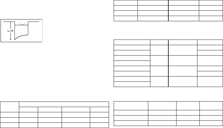
en • English
27
Telemetry data for Japan:
In accordance with Japanese law, this device has been assigned an identification
number under the "Ordinance concerning certification of conformity with technical
regulations etc. of specified radio equipment", Article 2-1-8.
•
R: 202-LSD078
Pulse form
The pacing pulse has the following form:
The pulse amplitude reaches its maximum value at the beginning of the pulse (Ua).
With increasing pacing duration (tb), the pulse amplitude is reduced dependent on the
pacing impedance.
Resistance to interference
•
Note on device type VR DX (only devices with a DF-1/IS-1 connection): The EMC
requirements are met as long as atrial sensitivity is set to 1.0 mV (factory settings)
or values ≥ 1.0 mV. Measures must be taken to assure interference-free therapy if
more sensitive values are set.
•
Note on device type HF and HF QP: In the case of unipolar sensing, the requirement
for interference voltages of ≤ 0.3 mV (peak to peak) is met.
Common mode rejection ratio
*Devices with a DF-1/IS-1 connection only; ** Information for device type HF also
applies to device type HF QP.
ATP amplitude
A burst was measured at 500 Ω, an amplitude of 7.5 V (tolerance ± 1.5 V), pulse width of
1.5 ms, R-S1 interval of 300 ms and an S1 count of 5:
Automatic sensitivity control
Measurement of actual values and test signal wave shape: standard triangle. For the
device type VR DX, the programmed atrial sensitivity is intensified by a factor of 4.
Shock energy / peak voltage
With shock path: RV to housing + SVC
Rate Common mode rejection ratio
Atrium: DX* Atrium: DR, HF** V right: VR, DR, HF** V left: HF**
16.6 Hz 76 dB 72 dB 58 dB 55 dB
50 Hz 73 dB 72 dB 65 dB 55 dB
60 Hz 75 dB 71 dB 66 dB 62 dB
ATP amplitude Measured minimum Measured maximum Mean value
RA 7.23 V 7.27 V 4.93 V
RV 7.26 V 7.52 V 5.04 V
LV 7.51 V 7.54 V 5.07 V
Sensitivity Value Tolerance Measured value
A: positive 0.2 mV 0.2 ... 0.5 0.27 mV
A: negative 0.26 mV
DX: A: positive 0.2 mV 0.2 ... 0.52
(0.05 to 0.13)
0.11 mV
DX: A: negative
RV: positive 0.5 mV 0.3 ... 0.7 0.53 mV
RV: negative 0.57 mV
LV: positive 0.5 mV 0.3 ... 0.7 0.53 mV
LV: negative
Shock energy
(Tolerance) Tolerance
Peak voltage Measured value
Shock energy Measured value
Peak voltage
1 J (0.7 ... 1.18) 90 ... 120 V 0.83 J 98.1 V
20 J (15.9 ... 21.6) 440 ... 480 V 17.4 J 462 V
40 J (33.8 ... 41.4) 620 ... 690 V 36.7 J 659 V
417634--B_GA_Intica-ProMRI_mul.fm Page 27 Friday, November 6, 2015 8:13 PM

28
Battery Data
Battery characteristics
The following data is provided by the manufacturers:
Storage period
The storage period affects the battery service time.
•
Devices should be implanted within 19 months between the manufacturing date
and the use by date (indicated on the package).
•
If the ICD is implanted shortly before the use by date, the expected service time
may be reduced by up to 17 months.
Calculation of service times
•
The services times have been calculated as follows – in all chambers depending on
the device type:
—
Pulse amplitude: 2.5 V
—
Pulse width: 0.4 ms
—
Pacing impedance: 500 Ω
—
Basic rate: 60 bpm
—
Home Monitoring: ON, 1 device message each day and 24 IEGM online HD
transmissions per year
—
Diagnostic functions and recordings: permanently set
•
Capacitor reforming is performed 4 times per year and therefore at least
4 maximum charges for shocks have to be assumed per year even if less than 4 are
delivered.
Calculation of the number of shocks
Calculation of the number of shocks: Service time [in years] x number of shocks per
year
Manufacturer GREATBATCH, INC.
Clarence, NY 14031 LITRONIK
Batterietechnologie GmbH
01796 Pirna, Germany
Battery type GB 2992 LiS 3410 RR
System Li/SVO/CFx LiMnO2
Battery ID number shown on
the programmer
36
Device type VR, VR DX, DR, HF, HF QP
Battery voltage at ERI 2.5 V 2.85 V
Charge time at BOS 8 s 8 s
Charge time at ERI 10 s 10 s
Usable capacity until ERI
5 series: VR, VR DX, DR, HF,
HF QP
7 series: VR, VR DX, DR
1390 mAh 1390 mAh
Usable capacity until ERI:
7 series: HF, HF QP
1600 mAh —
Usable capacity until EOS 1730 mAh 1520 mAh
417634--B_GA_Intica-ProMRI_mul.fm Page 28 Friday, November 6, 2015 8:13 PM

en • English
29
Intica 5/7 VR-T
Service times with GB 2992 or LiS 3410 RR battery:
Intica 5/7 VR-T DX
Service times with GB 2992 or LiS 3410 RR battery:
Intica 5/7 DR-T
Service times with GB 2992 or LiS 3410 RR battery:
Intica 5 HF-T (QP)
Service times with GB 2992 or LiS 3410 RR battery:
Intica 7 HF-T (QP)
Service times with battery GB 2992 without multipolar pacing:
Service times with battery GB 2992 with multipolar pacing:
Pacing Service time [in years] at number of shocks per year
48121620
0%
10.3 8.3 7.0 6.0 5.3
15%
10.1 8.1 6.8 5.9 5.2
50%
9.5 7.8 6.6 5.7 5.0
100%
8.8 7.3 6.2 5.4 4.8
Pacing Service time [in years] at number of shocks per year
48121620
0%
9.4 7.7 6.5 5.7 5.0
15%
9.2 7.6 6.4 5.6 4.9
50%
8.7 7.2 6.2 5.4 4.8
100%
8.1 6.8 5.9 5.2 4.6
Pacing Service time [in years] at number of shocks per year
48121620
0%
9.4 7.7 6.5 5.7 5.0
15%
9.0 7.4 6.3 5.5 4.9
50%
8.1 6.8 5.9 5.2 4.6
100%
7.1 6.1 5.3 4.7 4.3
Pacing Service time [in years] at number of shocks per year
4 8 121620
0%
8.9 7.4 6.3 5.5 4.9
15%
8.3 7.0 6.0 5.2 4.7
50%
7.2 6.1 5.4 4.8 4.3
100%
6.0 5.3 4.7 4.2 3.9
Pacing Service time [in years] at number of shocks per year
4 8 121620
0%
10.1 8.4 7.2 6.3 5.5
15%
9.4 7.9 6.8 6.0 5.3
50%
8.2 7.0 6.1 5.5 4.9
100%
6.9 6.0 5.4 4.8 4.4
Pacing Service time [in years] at number of shocks per year
4 8 121620
0%
10.1 8.4 7.2 6.3 5.5
15%
9.2 7.8 6.7 5.9 5.3
50%
7.7 6.6 5.9 5.2 4.7
100%
6.2 5.5 5.0 4.5 4.1
417634--B_GA_Intica-ProMRI_mul.fm Page 29 Friday, November 6, 2015 8:13 PM
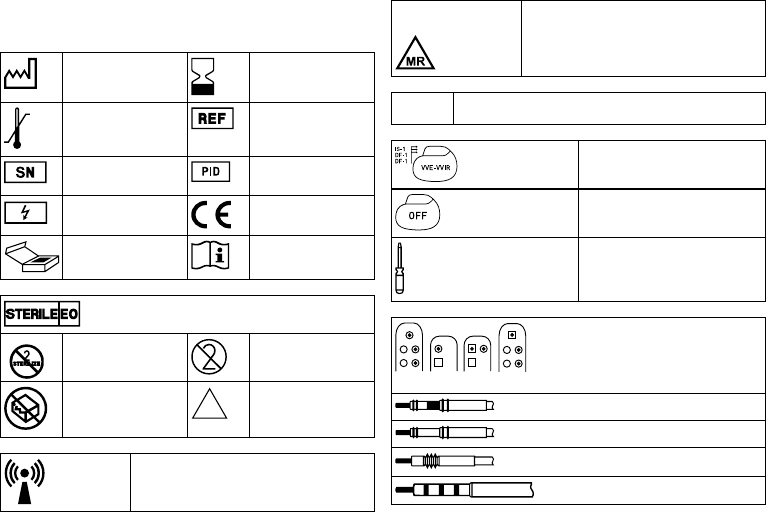
30
Legend for the Label
Label on the package
The label icons symbolize the following:
Manufacturing date Use by
Storage temperature Order number
Serial number Product identification
number
Dangerous voltages! European approval mark
Contents Consult the instructions for
use
Sterilized with ethylene oxide
Do not resterilize Single use only.
Do not reuse!
Do not use if packaging is
damaged
Non-sterile
Transmitter with non-ionizing radiation at designated
frequency
NON
STERILE
Label icon on devices with
ProMRI
®
:
MR conditional: Patients having a device system
implanted whose components are labeled with this
symbol on the packaging can be examined using an
MR scan under precisely defined conditions.
TP2
Compatibility with telemetry protocol version 2
of BIOTRONIK Home Monitoring
Example
Device:
NBG code and compatible leads
Example
Factory settings for therapy: OFF
Screwdriver
Examples of the connector allocation:
DF-1/IS-1, DF4/IS-1, DF4/IS4/IS-1
Bipolar IS-1 connector
Unipolar IS-1 connector
Unipolar DF-1 connector
IS4 connector, DF4 connector
417634--B_GA_Intica-ProMRI_mul.fm Page 30 Friday, November 6, 2015 8:13 PM