BIOTRONIK SE and KG TACHNXT implantable cardioverter defibrillator User Manual
BIOTRONIK SE & Co. KG implantable cardioverter defibrillator
UserManual.wiki
>
BIOTRONIK SE and KG
>
TACHNXT User Manual
>
15a_TACHNXT UserMan_Ilesto
Contents
1.
15a_TACHNXT UserMan_Ilesto
2.
15b_TACHNXT UserMan_Iforia
15a_TACHNXT UserMan_Ilesto
Navigation menu
Upload a User Manual
Namespaces
Wiki Guide
HTML
PDF
Info
Views
User Manual
Discussion / Help
Navigation
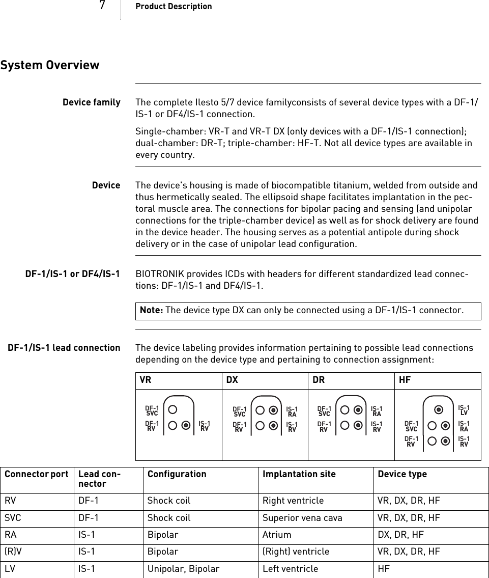
![1Ilesto 5/7 VR-T, VR-T DX, DR-T, HF-TICD Family Tachyarrhythmia Therapy Cardiac Resynchronization TherapyTechnical Manual for the DeviceDoc. Id.: GA-HW_en--mul_393468-BIndex GA-H W_en--mul_393468-BTechni cal[nbsp ]Manual for the[nbsp ]DeviceIlest o 5/7 VR-T, VR-T DX, DR-T, HF-T](https://usermanual.wiki/BIOTRONIK-SE-and-KG/TACHNXT.15a-TACHNXT-UserMan-Ilesto/User-Guide-1879842-Page-3.png)
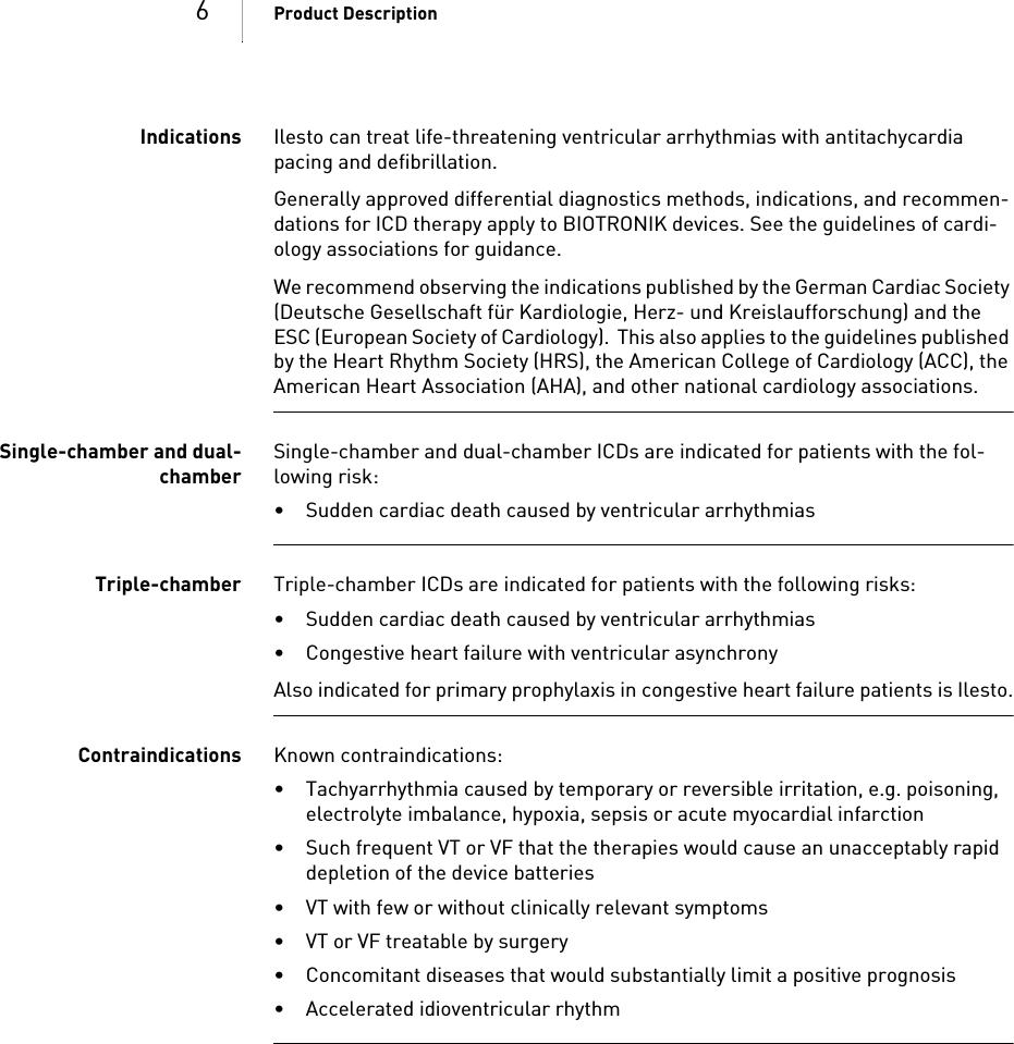
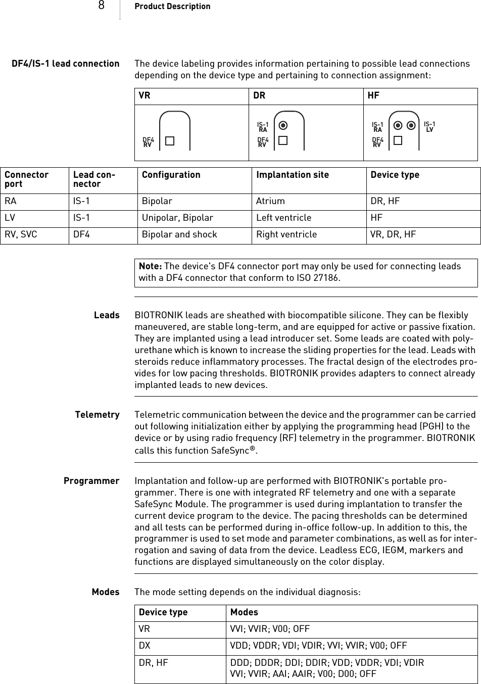
![5Product Description1 Product DescriptionProduct Description1G A-HW_en--mul_393468-BTechnical[nbs p ]Manual for the[nbsp ]DeviceIles to 5/7 VR-T, VR-T DX, DR-T, HF-TIntended Medical UseIntended use Ilesto 5/7 is part of a familiy of implantable cardioverter-defibrillators (ICDs). Primary objective of the therapy is to prevent sudden cardiac death. Furthermore, the device is capable of treating bradycardia arrhythmias and cardiac resynchroni-zation therapy with multisite ventricular pacing.The implantation of an ICD is a symptomatic therapy with the following objectives: • Termination of spontaneous ventricular fibrillation (VF) through shock delivery• Termination of spontaneous ventricular tachycardia (VT) through antitachy-cardia pacing (ATP); in case of ineffective ATP or hemodynamically not toler-ated VT, with shock delivery • Cardiac resynchronization through multisite ventricular pacing (triple-chamber devices)• Compensation of bradycardia through ventricular (single-chamber devices) or AV sequential pacing (DX, dual- and triple-chamber devices)Diagnosis and therapyformsThe device monitors the heart rhythm and automatically detects and terminates cardiac arrest resulting from ventricular tachyarrhythmia. All major therapeutic approaches from the field of cardiology and electrophysiology are included. BIO-TRONIK Home Monitoring® enables physicians to perform therapy management at any time.Required expertise In addition to having basic medical knowledge, the user must be thoroughly familiar with the operation and the operation conditions of a device system.• Only qualified medical specialists having this special knowledge required are permitted to use implantable devices.• If users do not possess this knowledge, they must be trained accordingly.](https://usermanual.wiki/BIOTRONIK-SE-and-KG/TACHNXT.15a-TACHNXT-UserMan-Ilesto/User-Guide-1879842-Page-7.png)
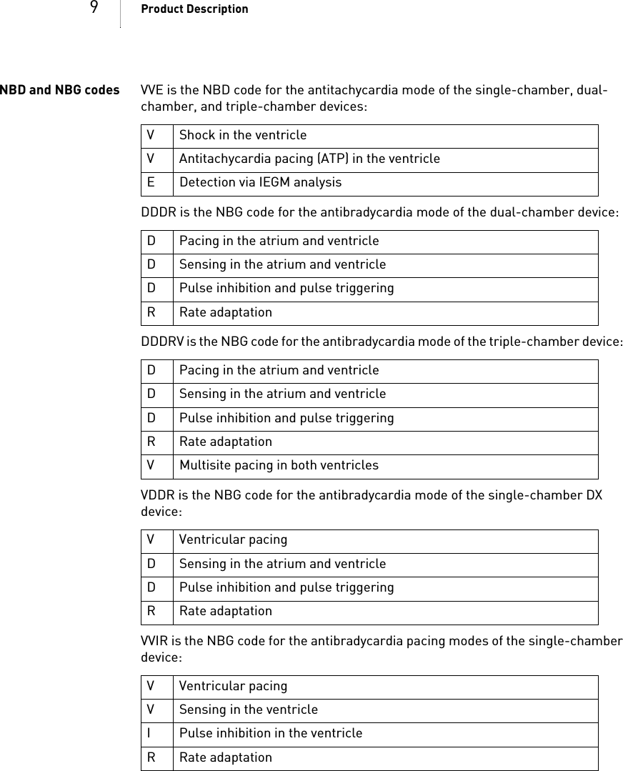
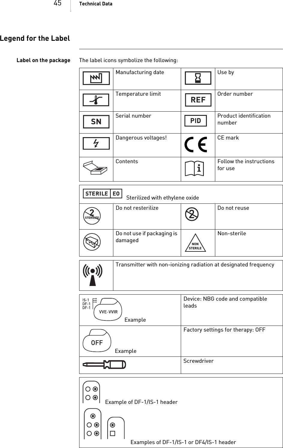
![13 General Safety Instructions2 General Safety InstructionsGeneral Safety Instructions2GA-HW_en--mul_39 3468-BTechnical[nbsp ]Manual for the[nbsp ]DeviceIlesto 5/7 VR-T, VR-T DX, DR-T, HF-TOperating ConditionsCare during shipping andstorage• Devices are not to be stored or transported close to magnets or sources of electromagnetic interference.• Note the effects of the storage duration; see Battery Data.Delivery in shipment mode The device is delivered in shipment mode to protect the battery; capacitor reforming required during storage could result in controlled extended charge times of the shock capacitors.• The shipment mode is displayed on the programmer after loading the device program (it is deactivated during implantation on initial measurement of the pacing impedance).Temperature Extremely low and high temperatures affect the service time of the battery in the device. • Temperatures of 5°C to 45°C are permitted for transport, storage, and use.Sterile delivery The device and the screwdriver have been gas-sterilized. Sterility is guaranteed only if the blister and quality control seal have not been damaged. Sterile container The device and screwdriver are packaged in two separately sealed blisters. The inner blister is also sterile on the outside so that it can be transferred in a sterile state during implantation.Single use only The device and screwdriver are intended for single use only. • Do not use the device if the package is damaged.• The device must not be resterilized and reused.](https://usermanual.wiki/BIOTRONIK-SE-and-KG/TACHNXT.15a-TACHNXT-UserMan-Ilesto/User-Guide-1879842-Page-15.png)
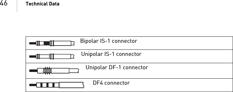
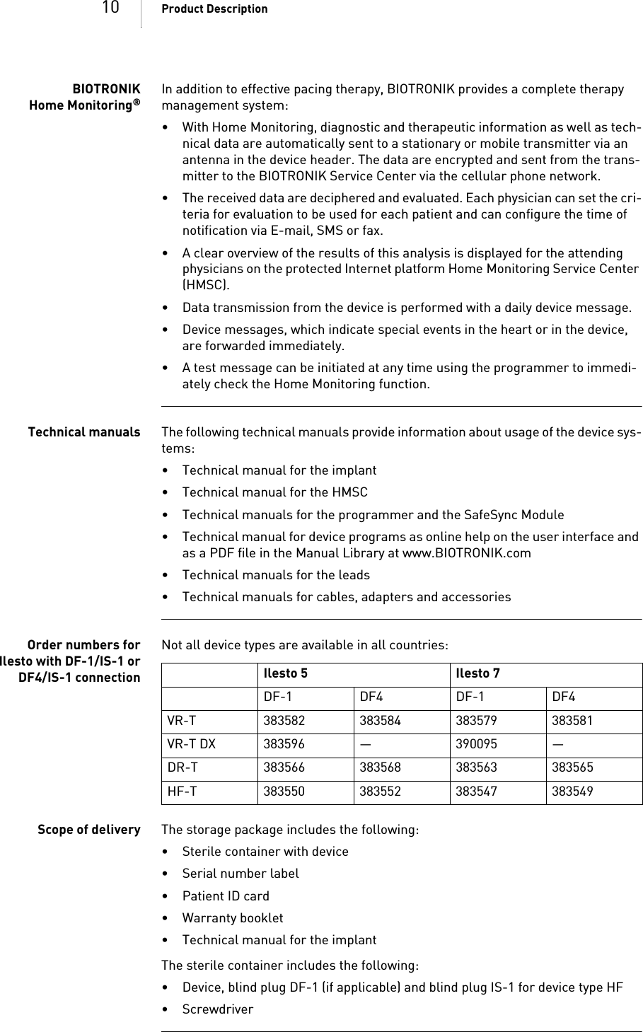
![17 Implantation3 ImplantationImplantation3 GA-HW_en--mul_393468-BTechnical[nbsp ]Manual for the[nbsp ]DeviceIlesto 5/7 VR-T, VR-T DX, DR-T, HF-TImplantation ProcedureHaving parts ready The following parts that correspond to the requirements of the EC Directive 90/385/EEC are required:• BIOTRONIK device with blind plug and screwdriver• BIOTRONIK leads and lead introducer set— Single-chamber device: One bipolar ICD lead with 1 or 2 shock coils for the ventricle — Dual-chamber device: One bipolar lead for the atrium and one bipolar ICD lead for the ventricle with 1 or 2 shock coils— Triple-chamber device: an additional unipolar or bipolar LV lead• DF-1, DF4 and IS-1 connections are approved. For leads with a different con-nection or leads from other manufacturers, use adapters approved by BIO-TRONIK only.• BIOTRONIK programmer (with integrated SafeSync RF telemetry or with sepa-rate SafeSync Module) and approved cable• External multi-channel ECG device• Keep spare parts for all sterile components.Keeping an external defi-brillator readyIn order to be able to respond to unforeseeable emergencies or possible technical failures of the device:• Keep an external defibrillator and paddles or patch electrodes ready.Unpacking the device• Peel the sealing paper off of the outer blister at the marked position in the direction indicated by the arrow. The inner blister may not come into contact with persons who have not sterilized their hands or gloves, nor with non-sterile instruments.• Take hold of the inner blister by the gripping tab and take it out of the outer blister.• Peel the sealing paper off of the sterile inner blister at the marked position in the direction indicated by the arrow.!!WARNINGInadequate therapy due to defective deviceIf an unpacked device is dropped on a hard surface during handling, electronic parts could be damaged. • Use a replacement device.• Return the damaged device to BIOTRONIK.](https://usermanual.wiki/BIOTRONIK-SE-and-KG/TACHNXT.15a-TACHNXT-UserMan-Ilesto/User-Guide-1879842-Page-19.png)
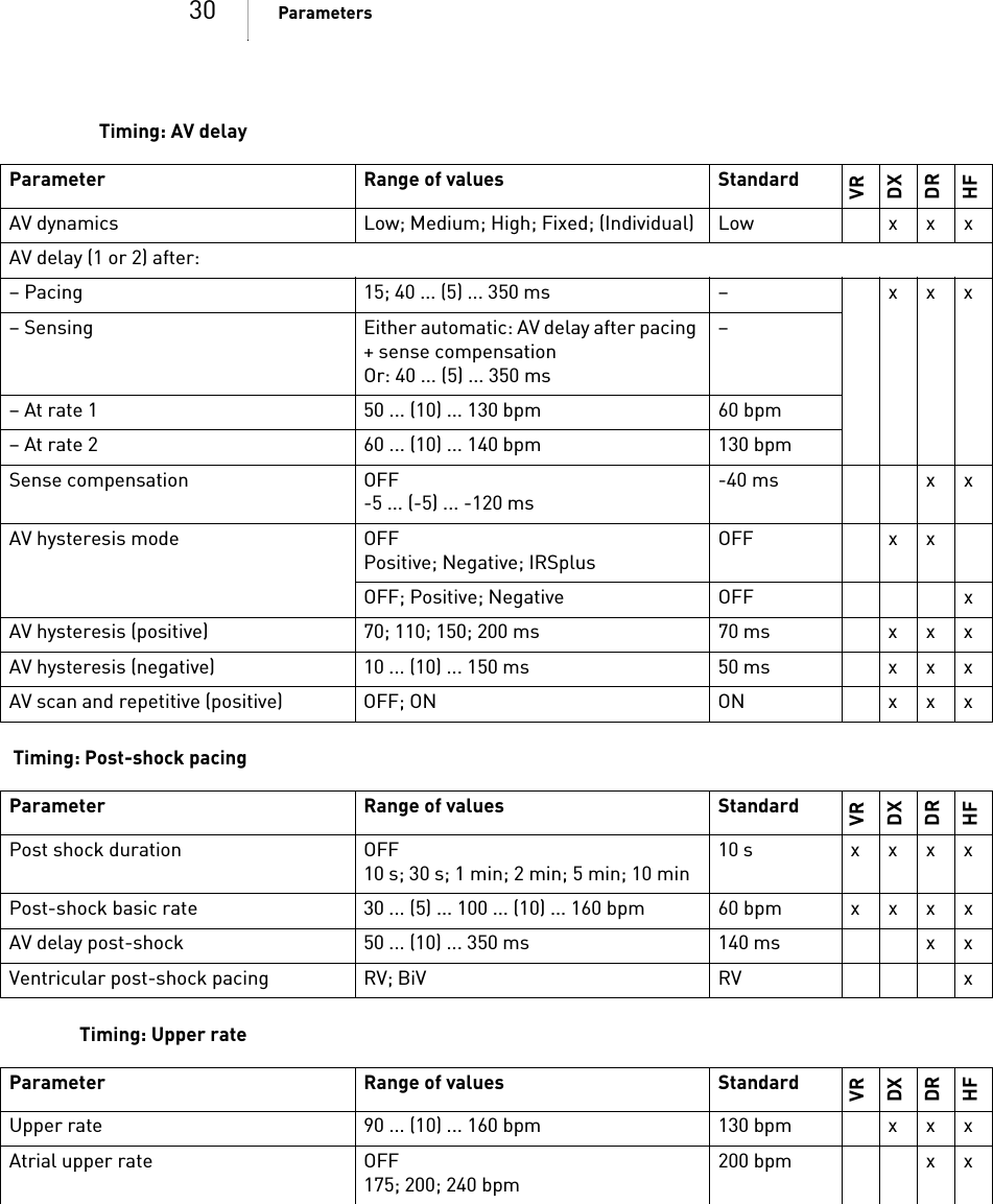
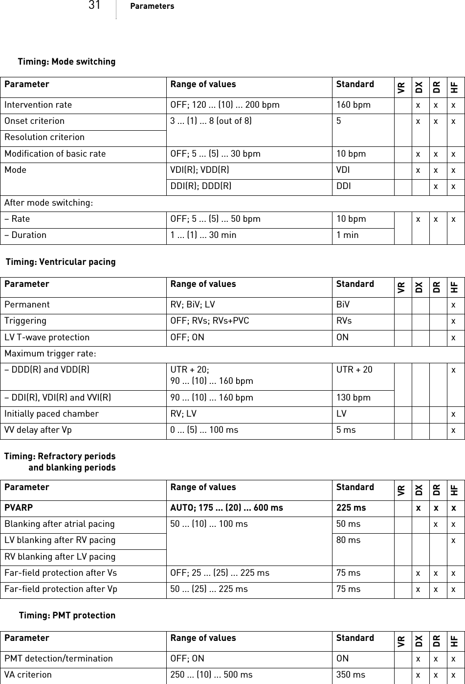
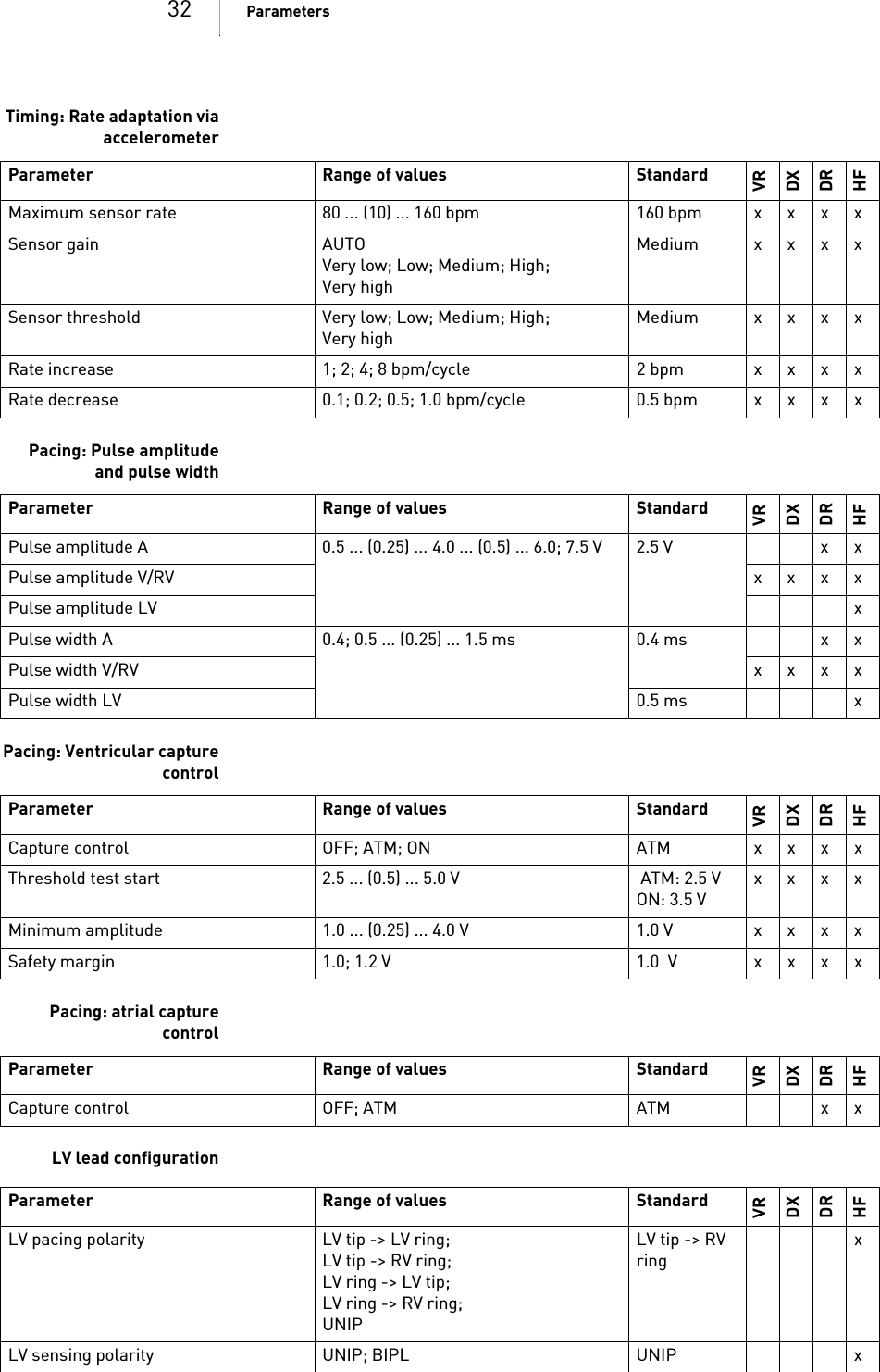
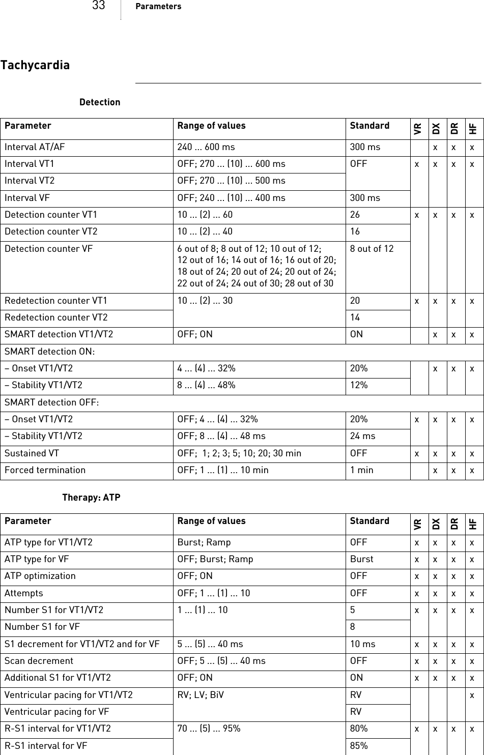
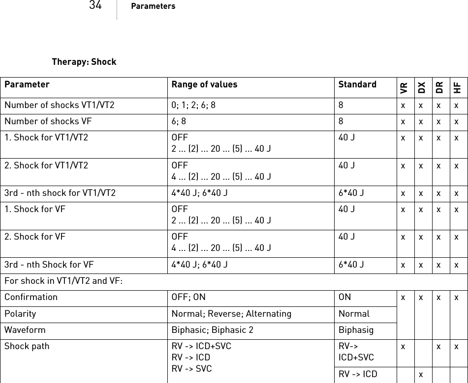
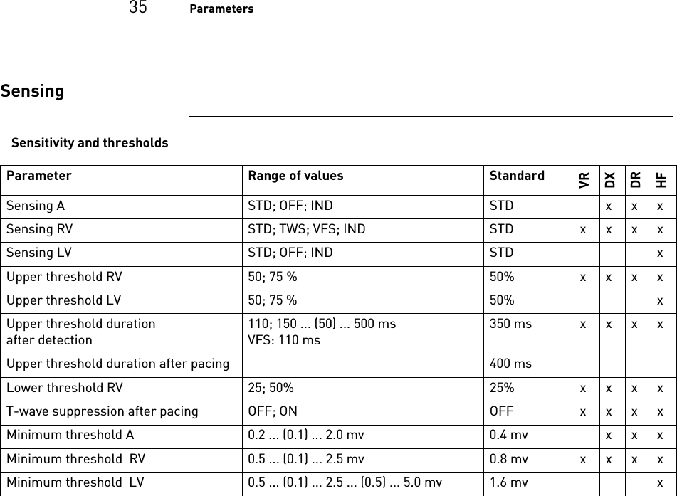
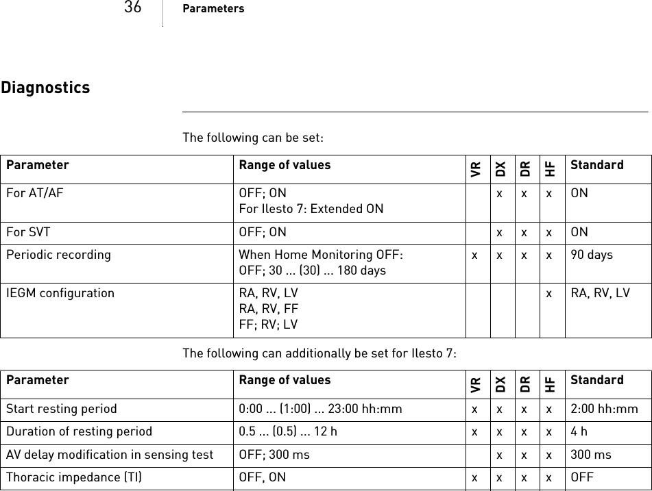
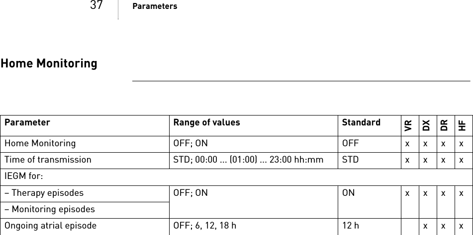
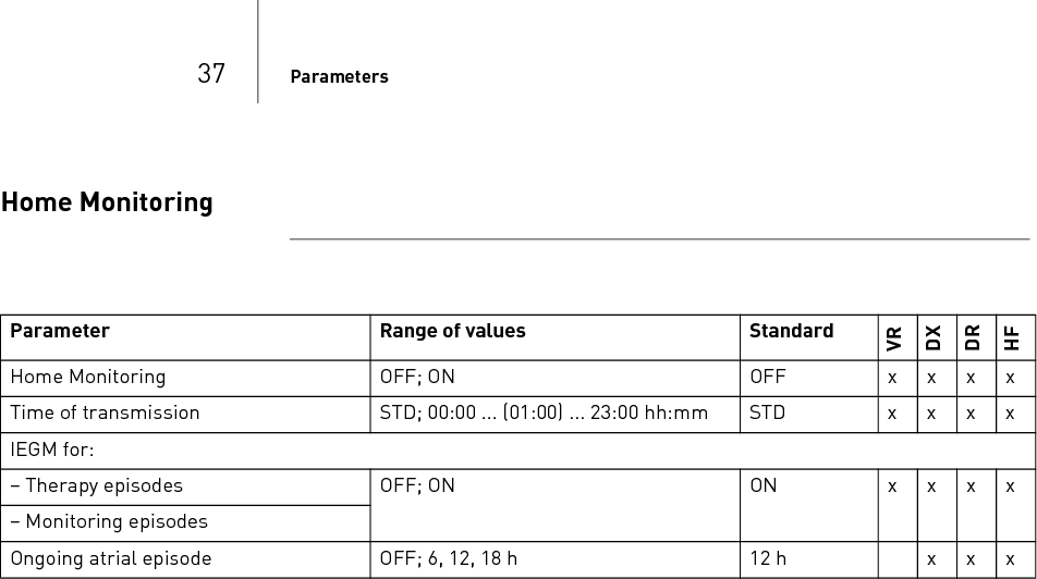
![29 Parameters4 ParametersParameters4GA-HW_en--mul_393468-BTechnical[nbsp ]Manual for the[nbsp ]DeviceIlesto 5/7 V R- T, VR-T DX, DR-T, HF-TBradycardia / CRTGeneral ICD therapyTiming: Basic rate day/night and rate hysteresesParameter Range of values StandardVRDXDRHFICD therapy OFF; ON ON xxxxPrograms Display standard program; Display safe program; Display first interro-gated program; Individual 1,2,3– xxxxParameter Range of values StandardVRDXDRHFBasic rate 30 ... (5) ... 100 ... (10) ... 160 bpm 40 bpm x x60 bpm x xNight rate OFF; 30 ... (5) ... 100bpm OFF xxxxBegin of night 00:00 ... (00:01) ...23:59hh:mm 06:00 hh:mmxxxxEnd of night 22:00 hh:mmRate hysteresis OFF-5 ... (-5) ... -25 ... (-20) ... -65 bpmOFF xxxxScan/repetitive OFF; ON ON xxxx](https://usermanual.wiki/BIOTRONIK-SE-and-KG/TACHNXT.15a-TACHNXT-UserMan-Ilesto/User-Guide-1879842-Page-31.png)
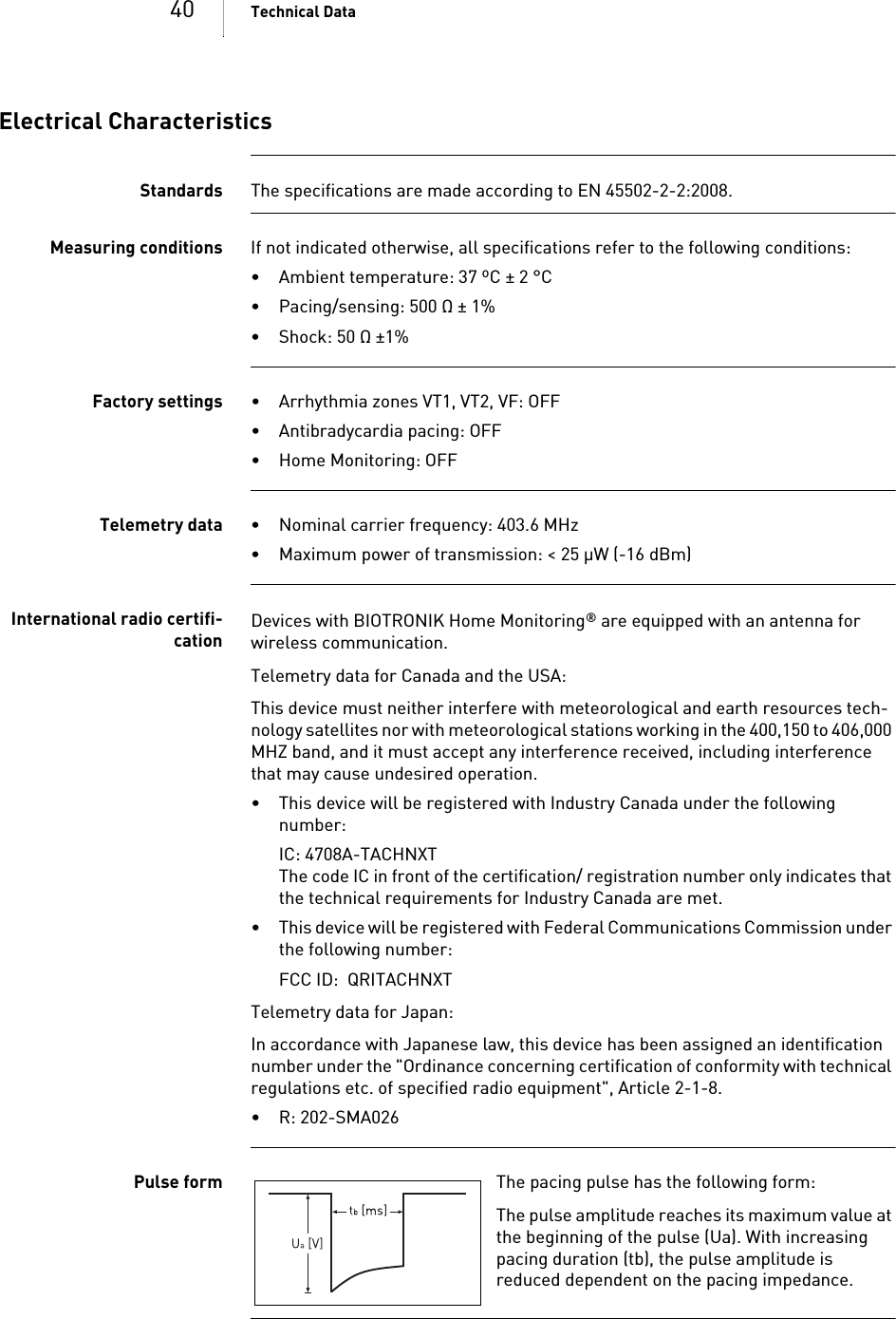
![39 Technical Data5 Technical DataTechnical Data5G A-HW_en--mul_393468-BTechnic al[nbsp ]Manual for the[nbsp ]DeviceI lesto 5/7 VR-T, VR-T DX, DR-T, HF-TMechanical CharacteristicsHousing Devices with a DF-1/IS-1 header: Devices with a DF4/IS-1 header: Materials in contact withbody tissue• Housing: Titanium• Header: Epoxy resin• Blind plug and silicone plug: Silopren or Silastik; DF4 seal: SilastikX-ray identification NTType Connection W x H x D in mm Volume in ccm Mass in gVR, DX, DR DF-1 65 x 55 x 11 31 80HF DF-1 65 x 58.5 x 11 33 80Type Connection W x H x D in mm Volume in ccm Mass gVR DF4 65 x 52 x 11 29.9 80DR DF4 65 x 56 x 11 31.5 80HF DF4 65 x 56 x 11 32.5 80](https://usermanual.wiki/BIOTRONIK-SE-and-KG/TACHNXT.15a-TACHNXT-UserMan-Ilesto/User-Guide-1879842-Page-41.png)
![42 Technical DataBattery DataBattery characteristics The following data is provided by the manufacturers: Storage period The storage period affects the battery service time.• Devices should be implanted within 19 months between the date of manufac-ture and the use by date (indicated on the package).• If the ICD is implanted shortly before the use by date, the expected service time may be reduced by up to 16 months.Calculation of service times • The services times have been calculated as follows – in all chambers depending on the device type:— Pulse amplitude: 2.5 V— Pulse width: 0.4 ms— Pacing impedance: 500 Ω—Basic rate: 60bpm— Home Monitoring: ON, 1 device message each day and 12 transmissions of an IEGM online HD per year— Diagnostic functions and recordings: permanently set• Capacitor reforming is performed 4 times per year and therefore at least 4 maximum charges for shocks have to be assumed per year even if less than 4 are delivered.Calculation of the numberof shocksCalculation of the number of shocks: Longevity [in years] x number of shocks per yearIlesto5VR-T Service times with GB 2992 or LiS 3410 RA battery: Manufacturer GREATBATCH, INC. Clarence, NY 14031 LITRONIK GmbH & Co01796 Pirna, GermanyBattery type GB 2992 LiS 3410 RABattery ID number shown on the programmer34Device type VR, (DX), DR, HFBattery voltage at ERI 2.5 V 2.85 VCharge time at BOS 8 s 8 sCharge time at ERI 10 s 10 sUsable capacity until ERI Ilesto 5: 1390 mAh Ilesto 7: 1600 mAh 1390 mAhUsable capacity until EOS 1730 mAh 1520 mAhStimulation Longevity [in years] at number of shocks per year4 8 12 16 200% 10.42 8.39 7.01 6.03 5.2815% 10.14 8.20 6.89 5.93 5.2150% 9.55 7.81 6.60 5.72 5.05100% 8.81 7.31 6.24 5.45 4.83](https://usermanual.wiki/BIOTRONIK-SE-and-KG/TACHNXT.15a-TACHNXT-UserMan-Ilesto/User-Guide-1879842-Page-44.png)
![43 Technical DataIlesto 5 VR-T DX Service times with GB 2992 or LiS 3410 RA battery: Ilesto 5 DR-T Service times with GB 2992 or LiS 3410 RA battery: Ilesto5HF-T Service times with GB 2992 or LiS 3410 RA battery: Ilesto7VR-T Service times with GB 2992 battery: Ilesto 7 VR-T DX Service times with GB 2992 battery: Stimulation Longevity [in years] at number of shocks per year4 8 12 16 200% 9.48 7.76 6.57 5.70 5.0315% 9.24 7.61 6.46 5.61 4.9650% 8.75 7.26 6.21 5.42 4.81100% 8.12 6.83 5.89 5.17 4.62Stimulation Longevity [in years] at number of shocks per year4 8 12 16 200% 9.48 7.76 6.57 5.70 5.0315% 9.02 7.45 6.35 5.53 4.8950% 8.10 6.81 5.88 5.17 4.61100% 7.08 6.07 5.32 4.73 4.26Stimulation Longevity [in years] at number of shocks per year4 8 12 16 200% 8.78 7.29 6.23 5.44 4.8215% 8.21 6.89 5.94 5.21 4.6550% 7.14 6.12 5.35 4.76 4.28100% 6.01 5.27 4.69 4.23 3.85Stimulation Longevity [in years] at number of shocks per year4 8 12 16 200% 11.78 9.52 7.98 6.87 6.0315% 11.48 9.32 7.84 6.76 5.9550% 10.81 8.87 7.52 6.53 5.76100% 9.99 8.31 7.11 6.21 5.52Stimulation Longevity [in years] at number of shocks per year4 8 12 16 200% 10.73 8.82 7.48 6.50 5.7415% 10.48 8.65 7.36 6.40 5.6650% 9.92 8.26 7.08 6.19 5.50100% 9.22 7.77 6.71 5.91 5.27](https://usermanual.wiki/BIOTRONIK-SE-and-KG/TACHNXT.15a-TACHNXT-UserMan-Ilesto/User-Guide-1879842-Page-45.png)
![44 Technical DataIlesto 7 DR-T Service times with GB 2992 battery: Ilesto7HF-T Service times with GB 2992 battery: Stimulation Longevity [in years] at number of shocks per year4 8 12 16 200% 10.73 8.82 7.48 6.50 5.7415% 10.22 8.47 7.23 6.31 5.5950% 9.20 7.76 6.70 5.90 5.27100% 8.05 6.92 6.07 5.40 4.87Stimulation Longevity [in years] at number of shocks per year4 8 12 16 200% 9.96 8.29 7.10 6.20 5.5115% 9.33 7.85 6.77 5.95 5.3150% 8.12 6.97 6.11 5.43 4.89100% 6.85 6.01 5.36 4.83 4.40](https://usermanual.wiki/BIOTRONIK-SE-and-KG/TACHNXT.15a-TACHNXT-UserMan-Ilesto/User-Guide-1879842-Page-46.png)