BIXOLON SLP-T400R Thermal transfer label printer User Manual Manual
BIXOLON Co.,Ltd. Thermal transfer label printer Manual
UserManual.wiki
>
BIXOLON
>
SLP T400R User Manual
Manual
Navigation menu
Upload a User Manual
Namespaces
Wiki Guide
HTML
PDF
Info
Views
User Manual
Discussion / Help
Navigation
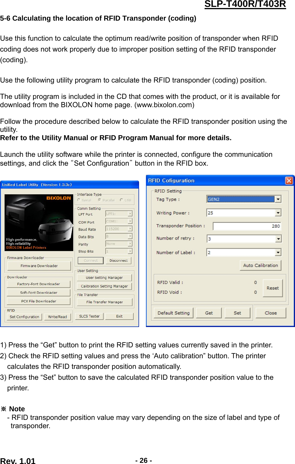
![Rev. 1.01 - 21 -SLP-T400R/T403R[Table 1] Dip Switch 1 No Functions Details Off 5.0 ips 1-1 Speed Selection On 6.0 ips 4 3 2 Density Off Off Off 6 Off Off On 8 Off On Off 10 Off On On 12 On Off Off 14 On Off On 16 On On Off 18 1-2 1-3 1-4 Density Selection On On On 20 Off Normal Mode 1-5 Exhibition Selection On Demo Mode Off Label Paper 1-6 Media Selection On Thermal Continuous Paper 1-7 Reserved Default --- off Off Back Feeding Enable 1-8 Back Feed Option On Back Feeding Disable [Table 2] Dip Switch 2 No Functions Details 2 1 Baud Rate Off Off 9,600 bps Off On 19,200 bps On Off 57,600 bps 2-1 2-2 Baud Rate Selection On On 115,200 bps Off Detect Gap 2-3 Media Detection On Detect Black Mark 1)Dip S/W 1-6 OFF: Reverse Side Black Mark 2)Dip S/W 1-6 On: Printed Side Black Mark (Option)off Enable 2-4 Ribbon Sensor On Disable 2-5 Reserved Default --- off Off Receive Buffer Full 2-6 Busy Condition On *Offline *Receive Buffer Full Off Enable 2-7 Paper End Sensor Status On Disable Off Disable 2-8 Long Label Split Printing On Enable](https://usermanual.wiki/BIXOLON/SLP-T400R/User-Guide-1669457-Page-21.png)