Users Manual

1
www.cmaxwireless.co.kr
WD-MSB P2P Module
User Manual
2
www.cmaxwireless.co.kr
Upgrade History
Date
Version
Comment
2013-09-13
V1.0
Release
2013-10-31
V1.1

3
www.cmaxwireless.co.kr
Contents
1. General Description ……………………………………………………………………………………………...….6
1.1 Features …………………………………………………………………………………………………………………………………..6
1.2 Applications ……………………………………………………………………………………………....……..…………….………6
1.3 Product description ………………………………………………………………………………………….…………………….6
1.4 Specification ……………………………………………………………………………………….…………….…………………….7
2. Installation ……………………………………………………………………………………………………….…….9
2.1 Fundamentals of wireless LAN ……………………………………………………………………………………………….9
2.1.1 Infrastructure Mode ……………………………………………………………………………………………………….9
2.1.2 Ad-hoc Mode …………………………………………………………………………………………..………………….10
2.1.3 Basic Requisites …………………………………………………………………………………………………………...10
2.1.4 Authentication and Security ………………………….…………………………………………………………….11
2.2 Installation …………………………………………………………………………………………………………………………….11
2.2.1 Making Wireless LAN Network ………………………………………………………………………………….12
3. Configuration …………………………………………………………………………..…………………………….15
3.1 Configuration with WLAN Module Manager ……………………………………………………………………...15
3.1.1 Configuration via WLAN ………………………..…………………………………………………………………….15
3.1.2 Configuration via Serial ……………………………………………………………………………………………....16
3.1.3 Printer Search ……………………………………………………………………………………..……………………….16
3.1.4 System ………………………………………………………………………………………………………...……………….17
3.1.5 Protocol ………………………………………………………………………………………….......................................17
3.1.6 BSS Info …..……………………………………………………………………………………….....................................18
3.1.7 Network …………..…………………………………………………………………………………………………………...19
3.1.8 Authentication ……….…………………………………………………………………………………………………….20
3.1.9 Certification ……………………….….……………………………………………………………………………………..21
3.1.10 Firmware ………………….………………………………………………………………………………………………...21
3.1.11 Information ………………….…………………………………………………………………………………………....22
3.2 Web Configuration ……………………………………………………………………………………………………………....23
3.2.1 Web Connection ………………………………………………………………………………………………………...23
3.2.2 Home ……………………………….………………………………………………………………………………………….24
3.2.3 System …………………………………………………………………………………………………………………………25
3.2.4 Protocol ………………………….…………………………………………………………………………………………...26
3.2.5 Network ……………………………………………………………………………………………………………………...26

4
www.cmaxwireless.co.kr
3.2.6 Authentication …………………………………………………………………………………………………………....27
3.2.7 Wizard ………………………………………………………………………………………………………………………...28
3.2.8 Web Site ……………………………………………………………………………………………………………………..
3.2.9 Contact ……………………………………………………………………………………………………………………….
3.3 TELNET ………………………………………………………………………………………………………………………………….30
3.3.1 TELNET Connection …………………………………………………………………………………………………...30
3.3.2 System ………………………………………………………………………………………………………………………..31
3.3.3 Protocol ……………………………………………………………………………………………………………………...31
3.3.4 Network ……………………………………………………………………………………………………………………...32
3.3.5 Authentication …………………………………………………………………………………………………………...33
3.3.6 Save …………………………………………………………………………………………………………………………….37
3.3.7 Exit ……………………………………………………………………………………………………………………………...37
3.4 FTP ………………………………………………………………………………………………………………………………………..37
3.4.1 FTP Connection ………………………………………………………………………………………………………….37
3.4.2 Config File list view …………………………………………………………………………………………………...38
3.4.3 Config File download ………………………………………………………………………………………………...38
3.4.4 Config File Upload ……………………………………………………………………………………………………..38
3.4.5 Config File Specification ..…………………………………………………………………………………………..39
3.5 SNMP ……………………………………………………………………………………………………………………….…………...41
3.5.1 SNMP Connection ………………………………………………………………………………………….…………..41
3.5.2 SNMP Manager operation test…………………………………………………………………………………...42
4. Hardware Block Diagram ……………………………………………………………………………….………...45
4.1 Hardware Pin Array …………………………………………………………………………………………………….………...46
5. Demo and Test …………………………………………………………………………………………….………...48
5.1 Test environment ………………………………………………………………………………………………………….……….48
5.1.1 Hardware …………………………………………………………………………………………………………………....48
5.1.2 Software ……………………………………………………………………………………………………………….……..48
5.2 Start Test ……………………………………………………………………………………………………………………………….48
5.2.1 STEP1. ……………………………………………………………………………………………………….………………...48
5.2.2 STEP2. ……………………………………………………………………………………………………….………………...48
5.2.3 STEP3. ………………………………………………………………………………………………………….……………...48
6. Configuration Tool Command List ……………………………………………………………………………..49
6.1 Configuration Tool Protocol ……………………………………………………………………………….………………...49
6.1.1 Serial Operation Specification ….……………………………………………………………….………………..49
6.1.2 WLAN Operation Protocol & Port ………………………………………………………….……………..…..49
6.2 Serial & WLAN Command ……………………………………………………………………………….…………………..50
6.2.1 Serial Operation ………………………………………………………………………………………………………....50

5
www.cmaxwireless.co.kr
6.2.2 Wireless LAN Operation …………………………………………………………………………………………….51
6.2.3 Serial & Wireless LAN Command Format …………………………………………………………….…...51
7. Technical Support, Warranty, and Precaution ………………………………………………………….…...58
7.1 Technical Support ………………………………………………………………………………………….…………………...58
7.2 Warranty ………………………………………………………………………………………………………………………….…….58
7.2.1 Refund …………………………………………………………………………………………………………………….…..58
7.2.2 Free Repair Services …………………………………………………………………………………………………..58
7.2.3 Charged Repair Services …………………………………………………………………………………………....58
7.3 Precaution …………………………………………………………………………………………………………………………….58
6
www.cmaxwireless.co.kr
1. General Description
Wi-Fi P2P Module supports stand-alone WLAN system which embeds MCU (Micro Controller
Unit) with various configuration applications, monitoring functions and security protocols.
The stand-alone WLAN system, along with CMAX S/W package, can easily be adapted to target
systems which have RS-232 serial interface to enable wireless network (IEEE802.11 b/g/n)
functionality with no redesign of the system, thus making the system connected, controlled and
maintained in WLAN network.
2.1 Features
l Embedded 802.11b/g/n Wireless Networking
l Supports Serial to WLAN, Infrastructure, Ad-hoc mode
l Supports network status indicator LEDs
l UART/SPI Interface
l Strong Security with WEP 64/128, WPA/WPA2 Personal, Enterprise
l Supports DHCP Client, HTTP, HTTPS, TELNET, FTP, ARP, SNMP, IPv4, TCP, UDP Protocol
l Compact design 27mm × 36mm × 4.7mm
l Distance Outdoor: approx. 100m
2.2 Applications
l POS Equipment
l Automotive Applications
l Medical Equipment
l Street Furniture
l Telematics
l Industrial Automation
l Metering Applications
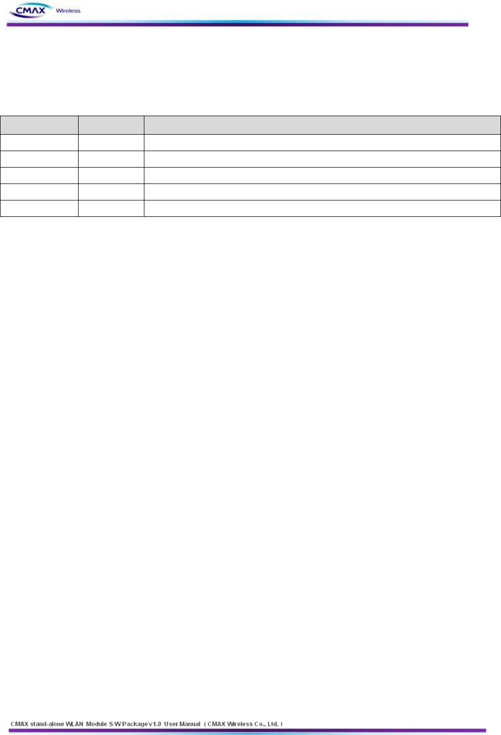
2.3 Product description
CATEGORIES
IMPLEMENTATION
Wi-Fi P2P Module
7
www.cmaxwireless.co.kr
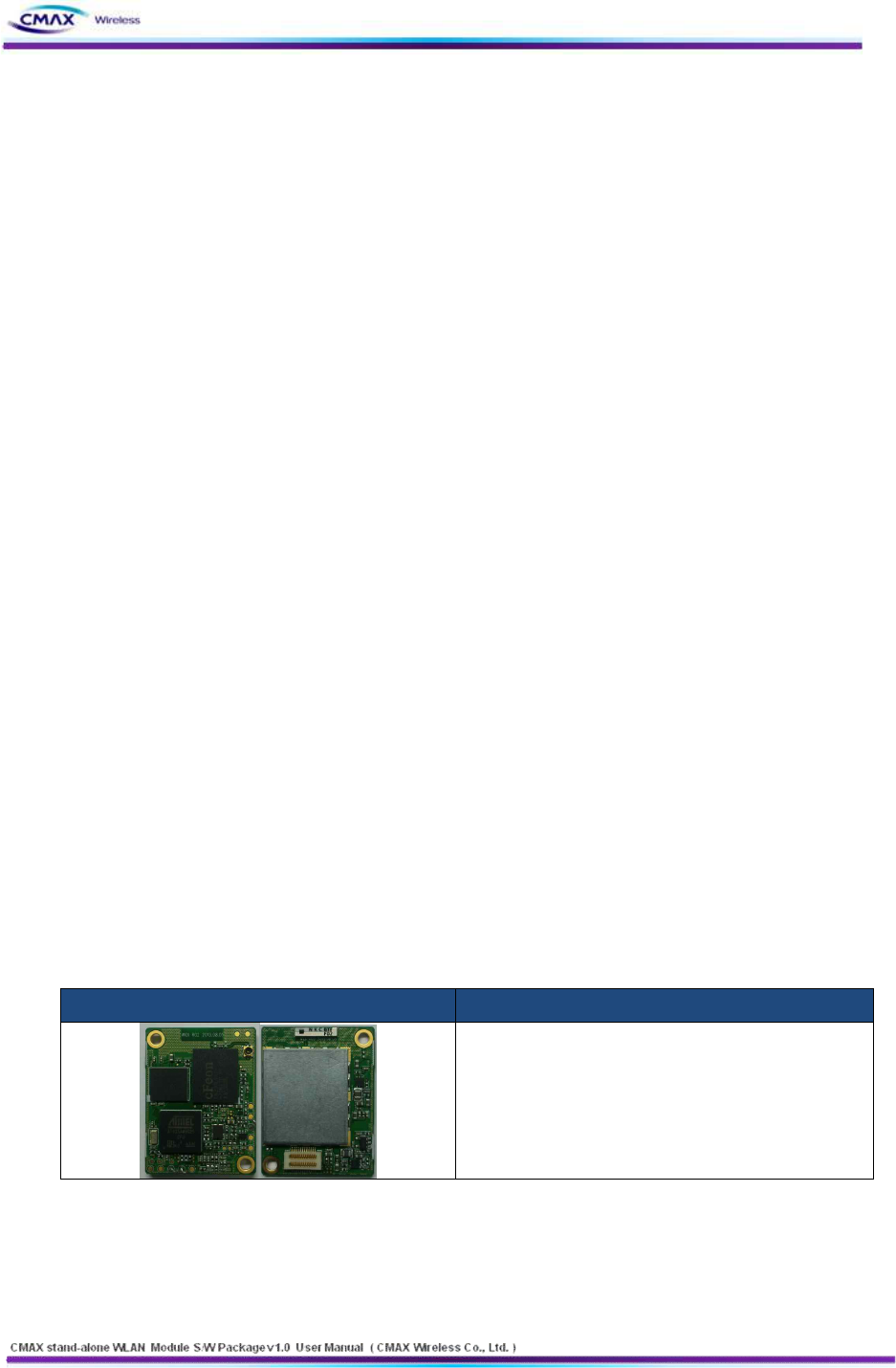
Debugger board
Serial Cable
(Serial Communication Cable)
Power
(DC 5V/1000mA Adapter)
CD
(User Manual and H/W, S/W Doc Package)
[Table 1.3.1] Product Description
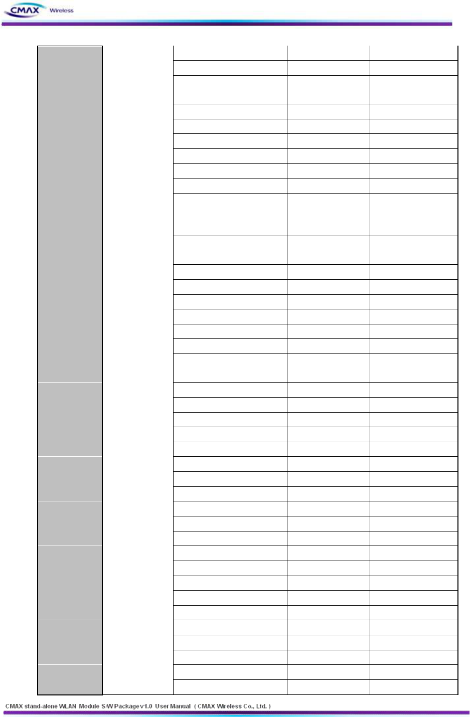
2.4 Specifications
ITEM
SPECIFICATIONS
WIRELESS SPECIFICATION
Wireless Standard
IEEE802.11b/g/n
Frequency Range
2.412~2.484GHz in 20Mhz
Channels
1 ~ 14 Channels
Baseband Processing
OFDM, CCK and DSSS
Modulation
BPSK, QPSK, 16-QAM, 64-QAM
Range
Up to 100m free space (Outdoor)
Connection Modes
Infrastructure/Ad-hoc (IBSS)/P2P
RF PERFORMANCE
Antenna Gain
2dBi ± 0.5 dBi, (internal chip antenna)
Tx EVM
25dB (54Mbps)
Tx Center Frequency Accuracy
20ppm
Tx Symbol Clock Frequency
Tolerance
20ppm
Tx Spectrum Mask
-21dBr @ fc +/- 11MHz
8
www.cmaxwireless.co.kr
-29dBr @ fc +/- 20MHz
-41dBr @ fc +/- 30MHz
Tx Spectral Flatness
2dB/ - 4dB
ANTENNA MODES
Antenna
To support two chip antenna or external two antenna via connector
UART INTERFACE
Baud Rate
230,400
Bits
8
Parity
None
Stop bits
1
Flow Control
CTS/RTS (Hardware)
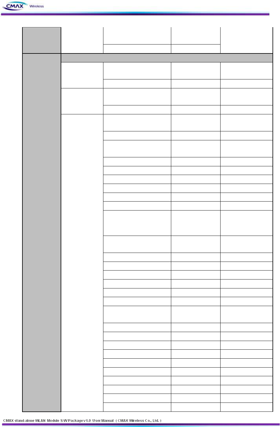
PROTOCOL
Internet
DHCP Client, HTTP, HTTPS, TELNET, FTP, ARP, ICMP, SNMP, IPv4,
TCP, UDP
Security
Open Connection
Shared Key (WEP encryption 64 and 128 bit options)
WPA1/2-Personal (PSK)
WPA1/2-Enterprise (EAP-TLS, EAP-TTLS, PEAP, LEAP, FAST)
SSL2 / SSL3 / TLS1
OTHERS
Management
Configuration Tool, HTTP, HTTPS, TELNET, FTP
Software Update
Firmware upgradeable via UART and Wireless LAN
PHYSICAL DIMENSION
Power
200mA * 3.3V
Dimensions
27mm × 36mm × 4.7mm
Weight
5g (Approx.)
Power Consumption
660mW
MCU
400MHz ARM9 with SRAM 64M and Flash 16M
Environmental
-5℃ ~ 55℃
-20℃ ~ 70℃
Humidity
Operation: 10% to 90%, Non-Condensing
Storage: 5% to 90%, Non-Condensing
[Table 1.4.1] Specification
9
www.cmaxwireless.co.kr
2. Installation
2.1 Fundamentals of wireless LAN
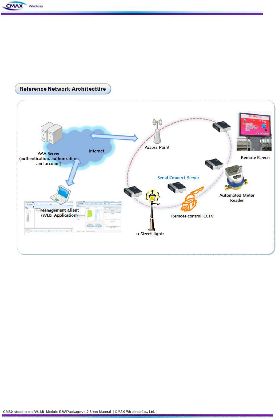
CMAX Module supports IEEE802.11b/g/n. This module support 11/54/72Mbps transmission
rate respectively. There are two types of wireless LAN networks – infrastructure and ad-hoc.
[Figure 2.1.1] Reference Network Architecture
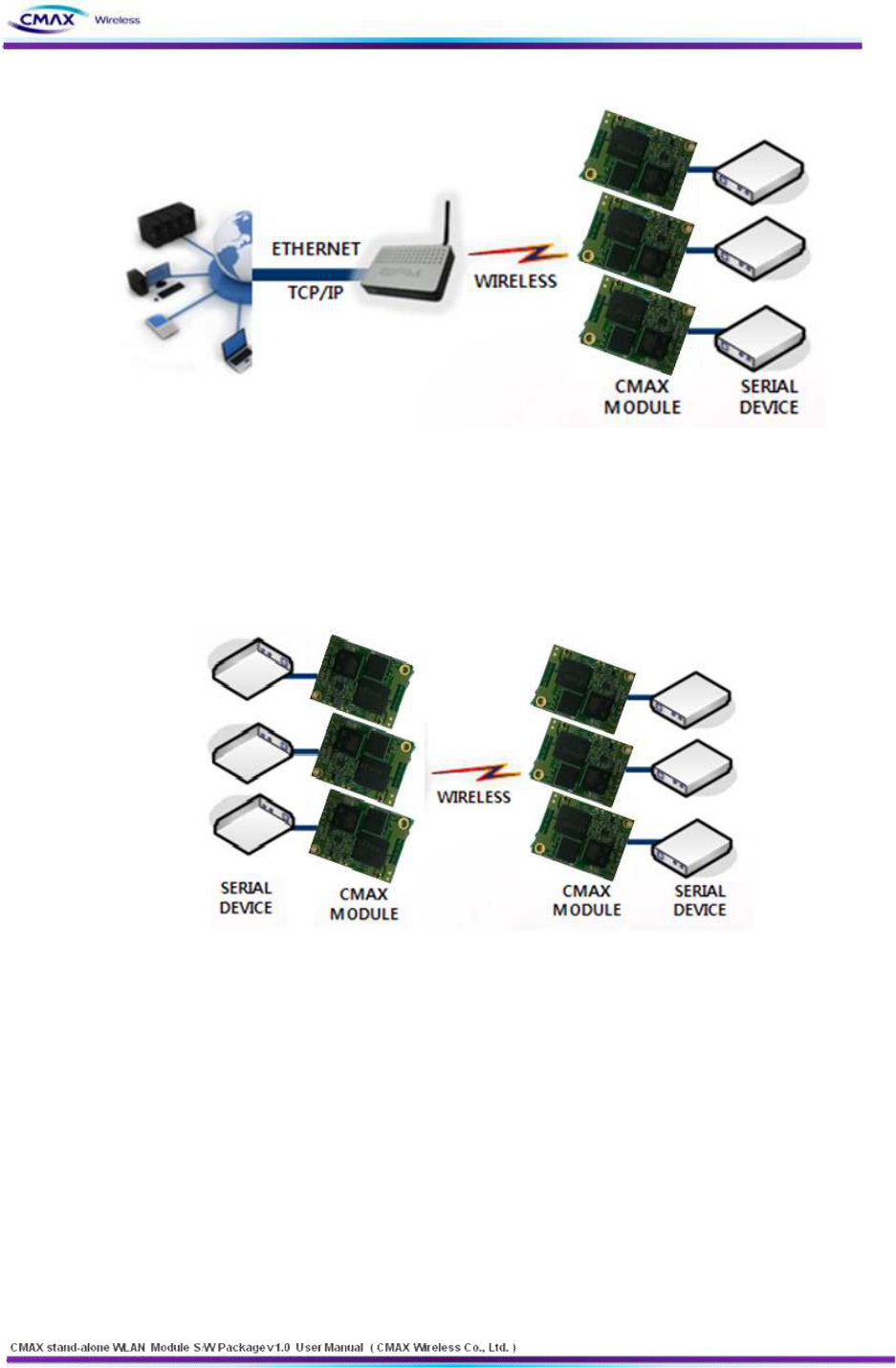
2.1.1 Infrastructure Mode
The wireless LAN stations communicate through an Access Point (AP). So, at least one AP
is needed to make the infrastructure network. The wireless LAN station can talk to wired
network hosts because AP relays between wireless LAN stations as well as between
wireless LAN station and wired LAN (Ethernet) host.
10
www.cmaxwireless.co.kr
[Figure 2.1.1.1] Infrastructure
2.1.2 Ad-hoc Mode
Wireless stations communicate each other without the AP. So user can make a system
more simply. It is proper if there’s no wired LAN requirement and it is a small network.
Some people call it peer-to-peer mode.
[Figure 2.1.2.1] Ad-Hoc
2.1.3 Basic Requisites
l SSID
It is an identifier to identify the particular wireless LAN. So the same SSID should be
configured to all stations to communicate in the same wireless network. In case of
infrastructure mode, user has to set his station’s SSID as same as AP’s.
l Channel
IEEE802.11b/g/n wireless LAN stations communicate through the ISM (Industrial,
Scientific, and Medical) band whose frequency is about 2.4GHz. IEEE802.11 specification
divides this band into 14 channels every 5MHz. If user installs more than one wireless

11
www.cmaxwireless.co.kr
LAN networks in the same area, the channels should be apart more than 4 channels to
avoid interferences.
2.1.4 Authentication and Security
l Authentication
A wireless LAN station should get authentication from the AP in the infrastructure mode.
There are the Open system and the Shared key for the authentication methods.
l WEP (Wired Equivalent Privacy)
The WEP is a secure protocol for wireless LAN. There are two kinds of WEP method - 64
bits and 128 bits key.
l WPA (Wi-Fi Protected Access)
WPA is a security standard for users of device equipped with Wi-Fi wireless connection.
It is an improvement on and is expected to replace the original Wi-Fi security standard,
Wired Equivalent Privacy (WEP). There are two modes about the user authentication in
WPA security. The one is Enterprise which has authentication server and the other one is
PSK (Pre-Shared Key) which dosen’t have any server. CMAX Module supports both
Enterprise mode and Personal mode (WPA-PSK).
l WPA 2
To final security of Wireless LAN, IEEE 802.11i, a standard about Wireless LAN, has
suggested the Counter Mode with Cipher Block Changing Message Authentication Code
Protocol (CCMP) for replacing the TKIP. CCMP uses Advanced Encryption Standard (AES),
it is the WPA 2 that adopts the using the method. WPA 2 has also both Enterprise and
PSK mode. CMAX Module supports also both them.
2.2 Installation
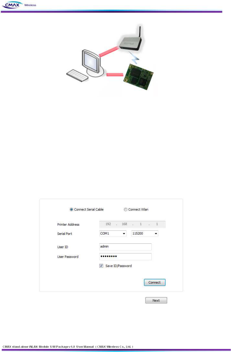
Before testing, users should connect the CMAX Module. There are two methods for
connecting. The first method is to connect a target device with the serial port and the other
method is to connect by wireless LAN card on your PC.
12
www.cmaxwireless.co.kr
[Figure 2.2.1] Connect between CMAX Module and a PC
2.2.1 Making Wireless LAN Network
Even though you connect an AP on your network, wireless LAN network could not be
made automatically. You should configure values of items which related with wireless
network. Please follow the below steps.
l Connect the CMAX Module through serial port
Start the WLAN Module Manager on your PC. Push the “Connect” button after
Selecting a COM port, User ID and User Password as the same values with the your COM
port.
[Figure 2.2.1.1] Connect through serial port
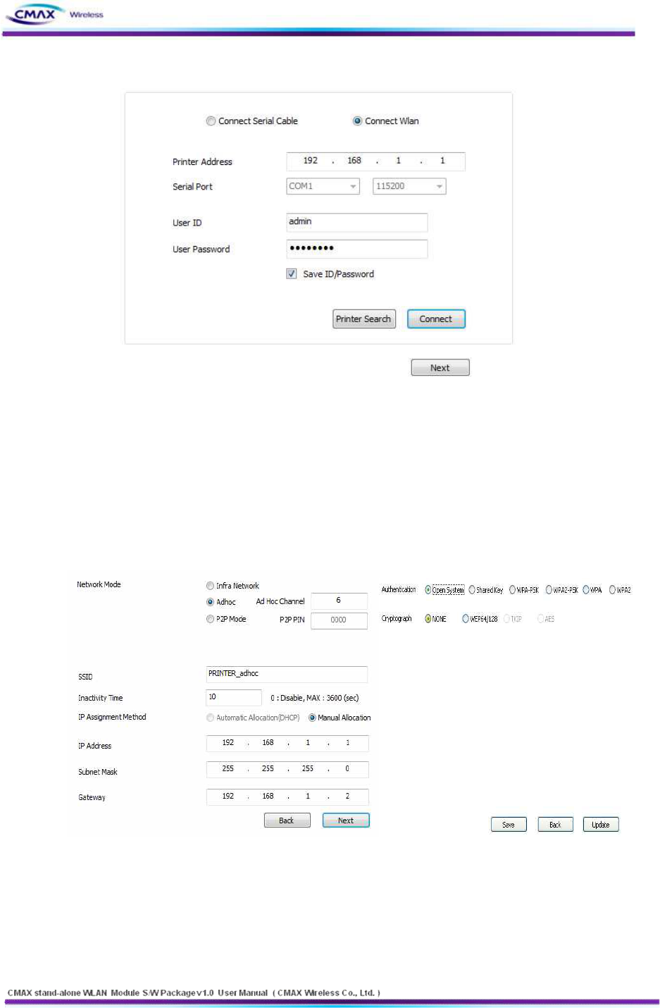
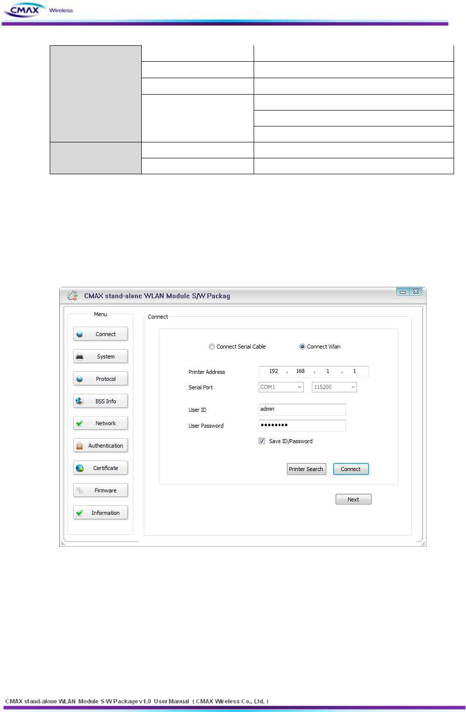
l Connect the CMAX Module through WLAN
Start the WLAN Module Manager on your PC. Click the “Connect” button after inserting
13
www.cmaxwireless.co.kr
IP Address, User ID and User Password as the same values with the CMAX Module.
[Figure 2.2.1.2] Connect through WLAN
l Configuring Wireless LAN Parameters
Move to the [Network] menu and setting SSID as the same values with the AP’s. Then,
move to the [Authentication] menu and setting security options. Finally, Click the
“Update” button. Please ask the manufacturer of the AP, when you want to know about
setting the AP’s value.
[Figure 2.2.1.3] Configuring Wireless LAN Parameters
If you want to make an Ad-hoc network, choose the [Ad-hoc] as the value of [WLAN
Topology] and set a value of [SSID]. Then, try to connect your PC to the network.
2.2.2 Setting Network Area
14
www.cmaxwireless.co.kr
This step is for setting both CMAX Module and your PC to be located the same network.
If only they are, the TCP connection between them can be established.
l Setting of the PC
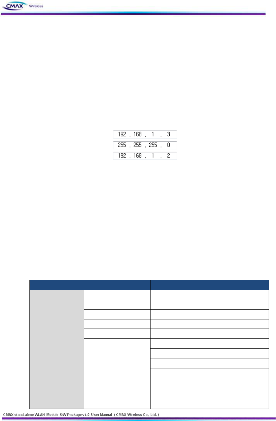
Add or change the IP address of the network adapter on your PC like following.
Get into the menu of [Windows Control Panel] >> [Network Connections] >> [Properties
of the Network Adapter - with right click of your mouse]. Then, you can show the
properties of [Internet Protocol (TCP/IP). In there, press the [Advanced] button for adding
an IP Address like the below figure.
[Figure 2.2.2.1] Adding / Changing the IP address of users’ PC (example)
l Setting of CMAX Module
CMAX Module uses WLAN Module Manager as it’s a configuration program. WLAN
Module Manager is for MS Windows, and this is comfortable to use because it doesn’t
need installation. First, search your WLAN Module via network. All the values of
parameters are set the default values in the factory. To apply it to your system, proper
values should be set via WLAN Module Manager. Major parameter’s default values are
listed on below table. To implement this simple test, keep these values without any
changes.
DISTRIBUTION
FUNCTION
VALUE
System
User ID
admin
User Password
password
Protocol
FTP
Disable
TELNET
Disable
HTTP
Enable / HTTPS is disable
SNMP
Disable
Community Name (Read) : Public
Community Name (Write) : Private
Trap Destination IP Address : 0.0.0.0
Trap Destination Community Name : Public
Trap Mode : 1 (Enable), 0 (Disable)
Network
Locality
Disable
15
www.cmaxwireless.co.kr
Network Mode
Ad-hoc, channel 1
SSID
PRINTER_adhoc
IP Assignment Method
Manual Allocation
IP, Subnet, Gateway
IP : 192.168.1.1
Subnet : 255.255.255.0
Gateway : 192.168.1.2
Authentication
Open System
None
Shared key
None
[Table 2.2.1.1] Default values of Major parameters
3. Configuration
3.1 Configuration with WLAN Module Manager
[Figure 3.3.1] initial appearance of WLAN Module
3.1.1 Configuration via WLAN
l Checklists
Make sure the WLAN connection between your PC and WLAN Module Manager. If they
are the same network, [search] button can be used. If they aren’t, [IP Address] should be
inserted to use.
l Procedures
16
www.cmaxwireless.co.kr
1) Printer Address : Set the values of the CMAX Module’s IP Address properly
2) User ID : Set the values of the User ID
3) User Password : Set the values of the Password
4) Connect : Connect through Wireless LAN to CMAX Module
5) Next : Move to System Configuration page.
Note : If you want to save [ID/Password], it choose the checkbox.
3.1.2 Configuration via Serial
l Checklists
Make sure the connection between your PC and WLAN Module Manager using RS232
direct cable. To use this, WLAN Module Manager has to be operating in the [Serial
Configuration] mode. You press the “Connect” button after Selecting a COM port, User ID
and User Password as the same values with the your COM port. Then, You can enter the
[Serial Configuration] mode.
l Procedures
1) Serial Port : Select a COM port as the same values with the your COM port.
2) User ID : Set the User ID
3) User Password : Set the User Password
4) Connect : Connect through Serial communication to CMAX Module
5) Next : Move to the configuration page of system
Note : If you want to save [ID/Password], it choose the checkbox. After changing the
configuration, you must be rebooted CMAX Module.
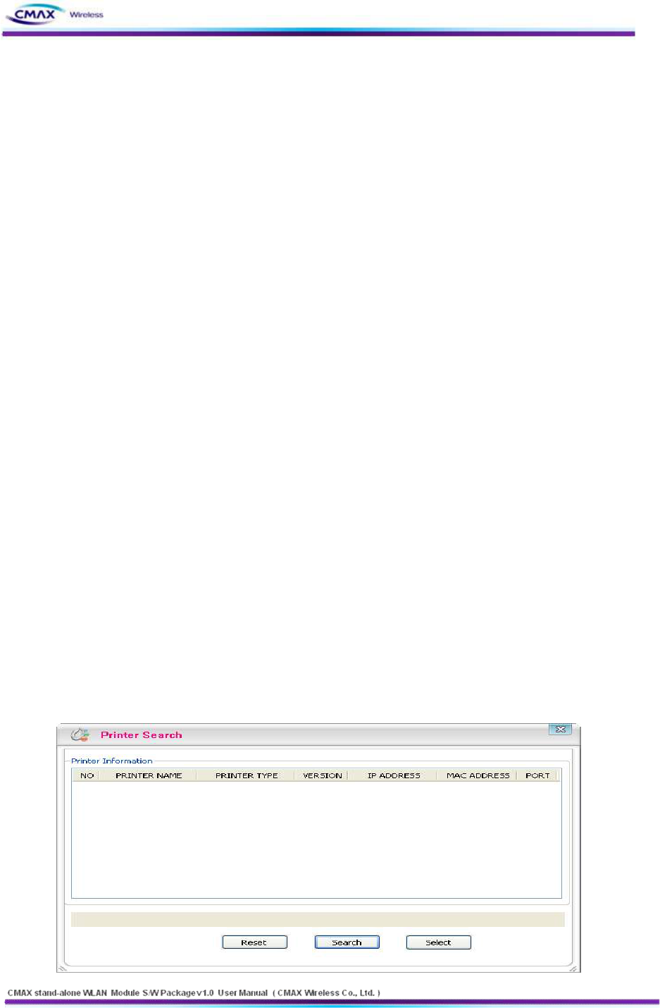
3.1.3 Printer Search
: Provide information of CMAX Module in the network.
17
www.cmaxwireless.co.kr
[Figure 3.1.3.1] Printer Search
l Reset : Delete the printer information
l Search : Search active printers in the network. If a network problem occurs, the printers
will not scan. Then, you press the [Search] button again.
l Select : After selecting a printer to connect, you should press [Select] button.
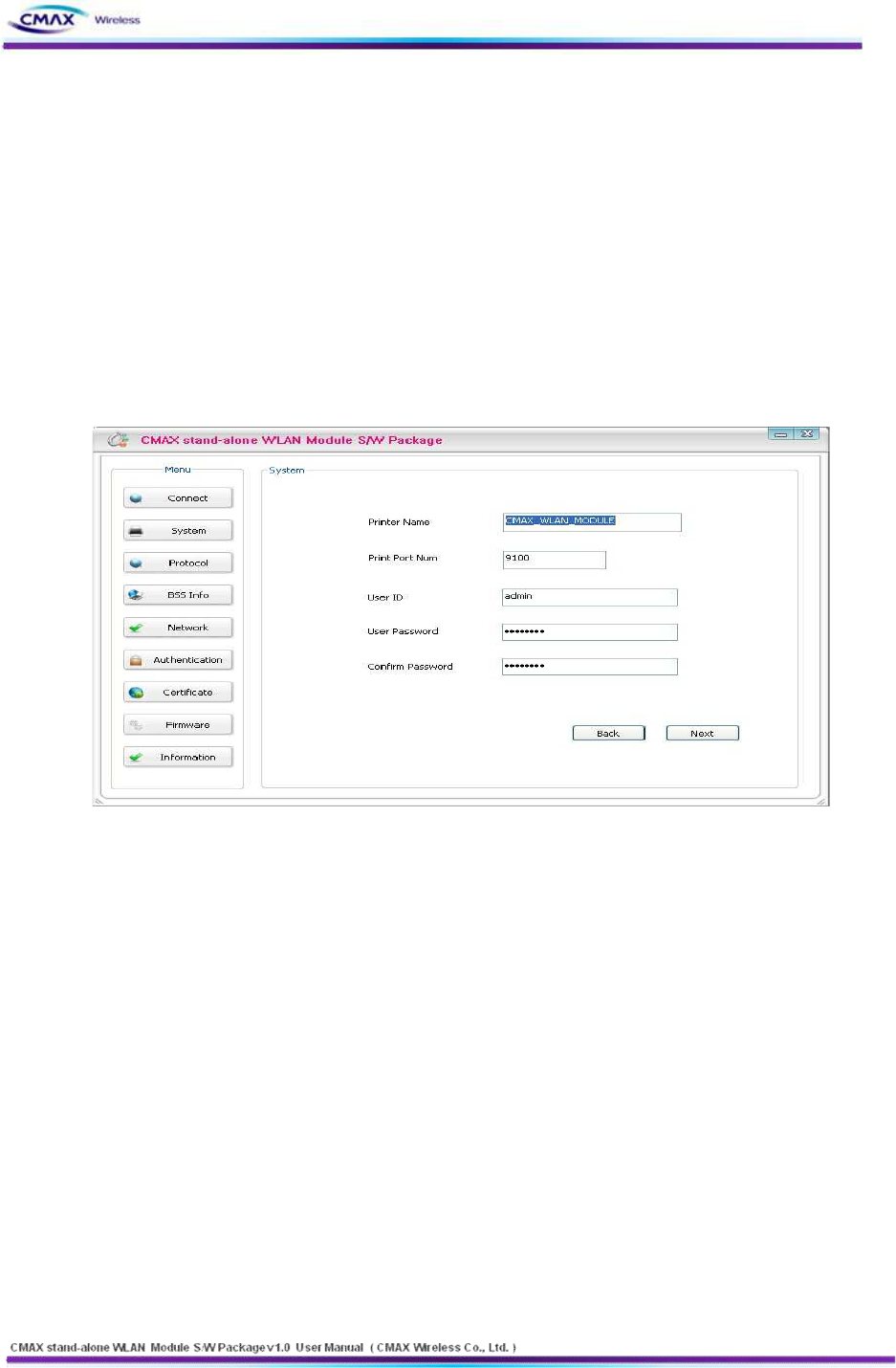
3.1.4 System
: Set the Printer Name, Printer Port Num, User ID and User Password. User ID and
password will be used to set the configuration.
[Figure 3.1.4.1] System Setting
l Printer Name : Set the [Printer Name]
l Print Port Num : Set the [Print Port Num]
l User ID : Set the [User ID]
l User Password : Set the [User Password]
l Confirm Password : Set correct values of [Confirm Password]
l Next : Move to the configuration page of protocol
l Back : Move to the configuration page of connection
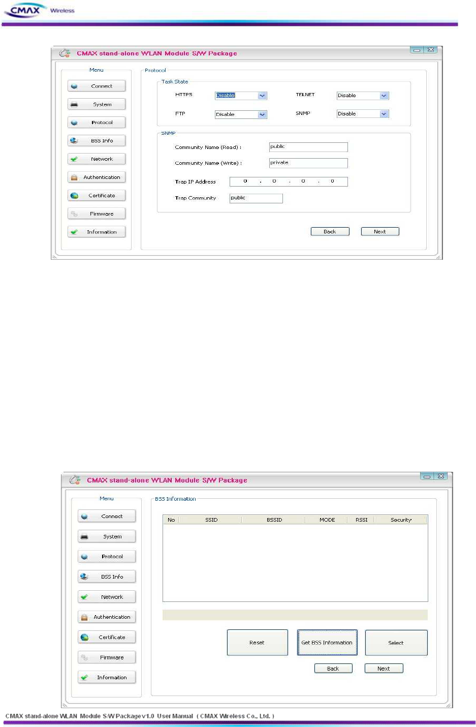
3.1.5 Protocol
: Select to use ftp, http and snmp that is application. For a description of each feature in
the manual can be found at.
18
www.cmaxwireless.co.kr
[Figure 3.1.5.1] Protocol Setting
l Task State
- Set the HTTPS, TELNET, FTP and SNMP that are applications if you use.
l SNMP
- To perform SNMP sets for each item.
l Next : Move to the configuration page of BSS Information
l Back : Move to the configuration page of System
3.1.6 BSS Info
: After Searching on AP(Access Point), user can select to connect at the AP. Then, AP’s
SSID will be inserted automatically.
19
www.cmaxwireless.co.kr
[Figure 3.1.6.1] BSS Setting
l Reset : Delete current information of BSSID
l Get BSS Information : Scanning information of BSSID. If the problem of network occurs,
the printers will not scan. Then, you press the [Get BSS Information] button again.
l Select : Select BSS that searched.
l Next : Move to the configuration page of Network
l Back : Move to the configuration page of Protocol
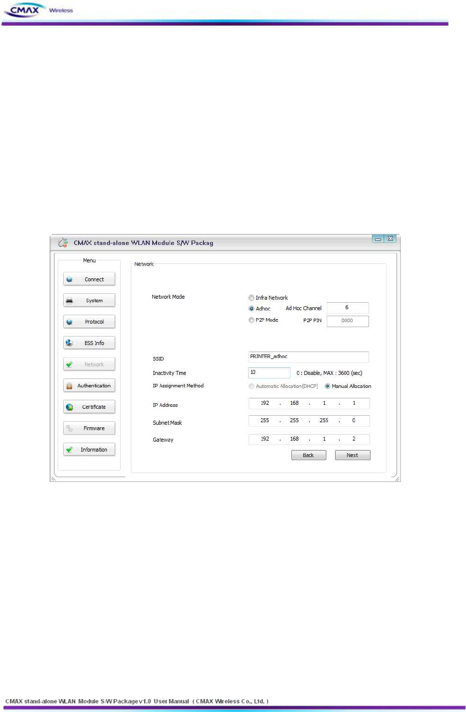
3.1.7 Network
: Set the network parameter of CMAX Module
[Figure 3.1.7.1] Network Setting
l Network Mode : Select the Infra Network or Adhoc mode.
Note : If adhoc mode user selects to connect a adhoc-channel (1~14).
l SSID : Set the SSID that user is going to connect. SSID Can set up maximum of 32 bytes.
l Inactivity Time : After connecting to the server of printer, It is time to maintain a
connection with the server. Default setting : Disable, Maximum time : 32767(sec)
l IP Assignment Method : Supported Automatic Allocation(DHCP Client) or Manual
Allocation. Default setting : Manual Allocation
- Automatic Allocation(DHCP Client) : Assigns the IP Address that is assigned in the
DHCP server automatically
- Manual Allocation : Does not assign the IP address in the AP(Access Point)’s DHCP
server. User should insert the IP Address that is such as IP Address of AP.
20
www.cmaxwireless.co.kr
l IP Address : Insert the [IP Address] of AP : Default IP Address : 192.168.192.168
l Subnet Mask : Insert the [Subnet Mask] of AP : Default subnet Mask : 255.255.255.0
l Gateway : Insert the [Gateway] of AP : Default Gateway : 192.168.192.1
l Next : Move to the configuration page of Authentication
l Back : Move to the configuration page of BSS Information
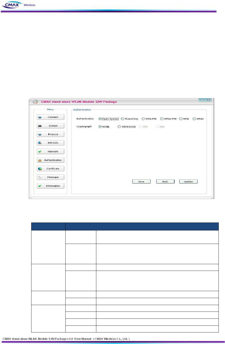
3.1.8 Authentication
: Set a security configuration of the CMAX Module
[Figure 3.1.8.1] Authentication Setting
l Authentication : It is security configuration between CMAX Module and AP(Access Point)
FIELD
DESCRIPTION
Open System
Cryptograph
It should be select NONE or WEP64/128 as the setting of AP to
be access
WEP Key
You can input the max 26charater,. It Configure to WEPB64/18 if
you input it like the following format.
- WEP64 (5 ASCII, 10 HEX), WEP128 (13 ASCII, 26 HEX)
Shared Key
Cryptograph
Select a WEP64/128 same AP’s configuration to be access.
WEP Key
You can input the max 26charater,. It Configure to WEPB64/18 if
you input it like the following format.
- WEP64 (5 ASCII, 10 HEX), WEP128 (13 ASCII, 26 HEX)
WPA-PSK /
WPA2-PSK
Cryptograph
You should same to configure a TKIP/AES with AP to be access.
PSK Key
You should same to input a TKIP/AES with AP to be access.
WPA-TKIP /
WPA2-AES
Cryptograph
You should same to configure a cryptograph with AP to be access.
EAP
You should same to configure a EAP Mode with AP to be access.
ID
You should Input the ID with configured certificate Server
Password
You should Input the Password with configured certificate Server
21
www.cmaxwireless.co.kr
However, If EAP Configuration is a EAP-TLS, you should input the
private_key_password that is certificate password that generated
for CMAX module.
[Table 3.1.8.2] Security setting
l Save : It is function to Save the configuration information that you have set
l Saved file can set through uploading with FTP
l Update : User will save the configuration information to CMAX Module
l Back : Move to the configuration page of Network
Note : To upload a file must be named “config” should be
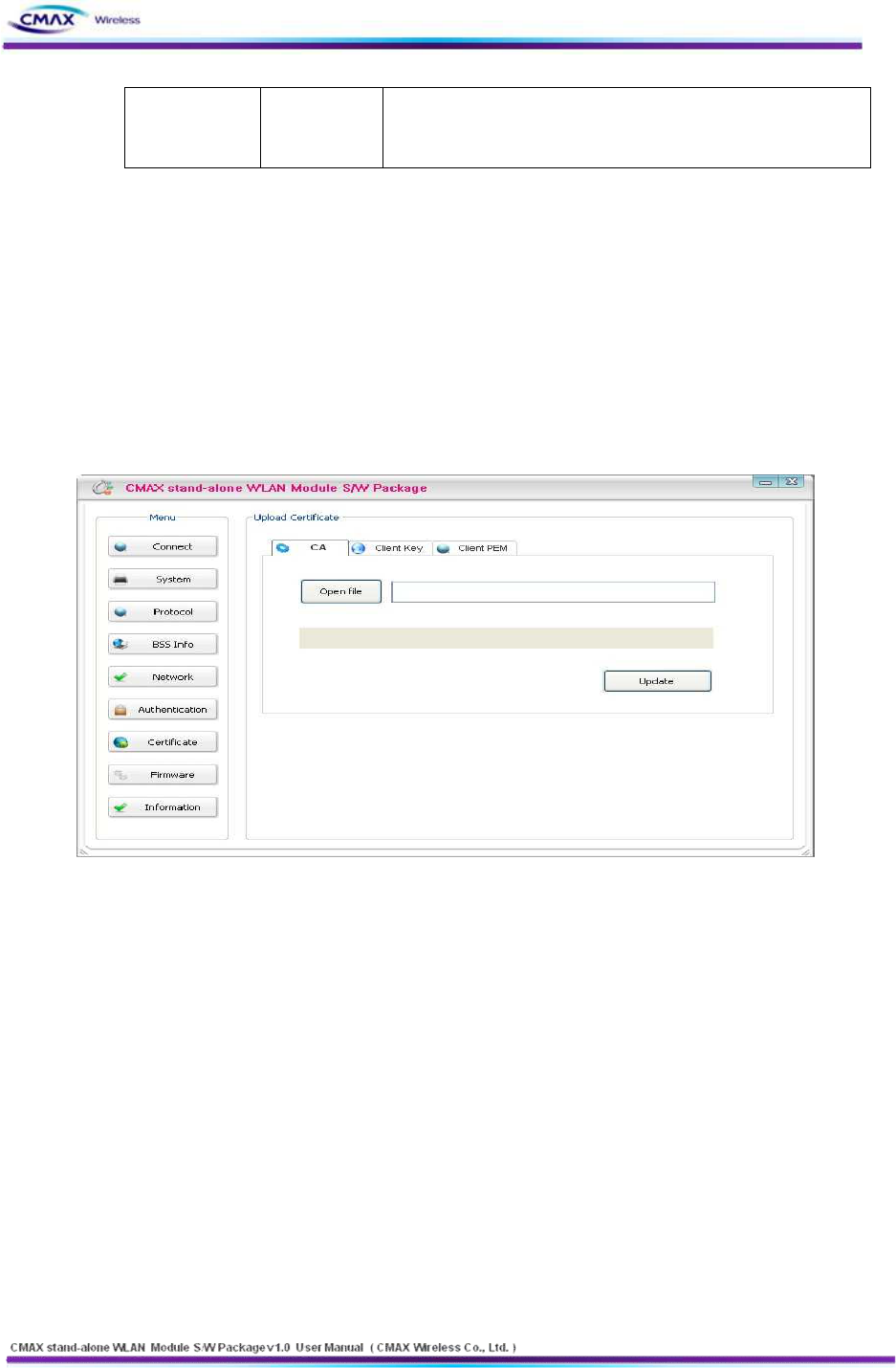
3.1.9 Certification
: Can upload Certificates to CMAX Module for EAP-TLS certification
[Figure 3.1.9.1] Upload Certificate
l Upload Certification
- Open file : Select the Certificate
- Update : Save the Selecting a certificate to CMAX Module
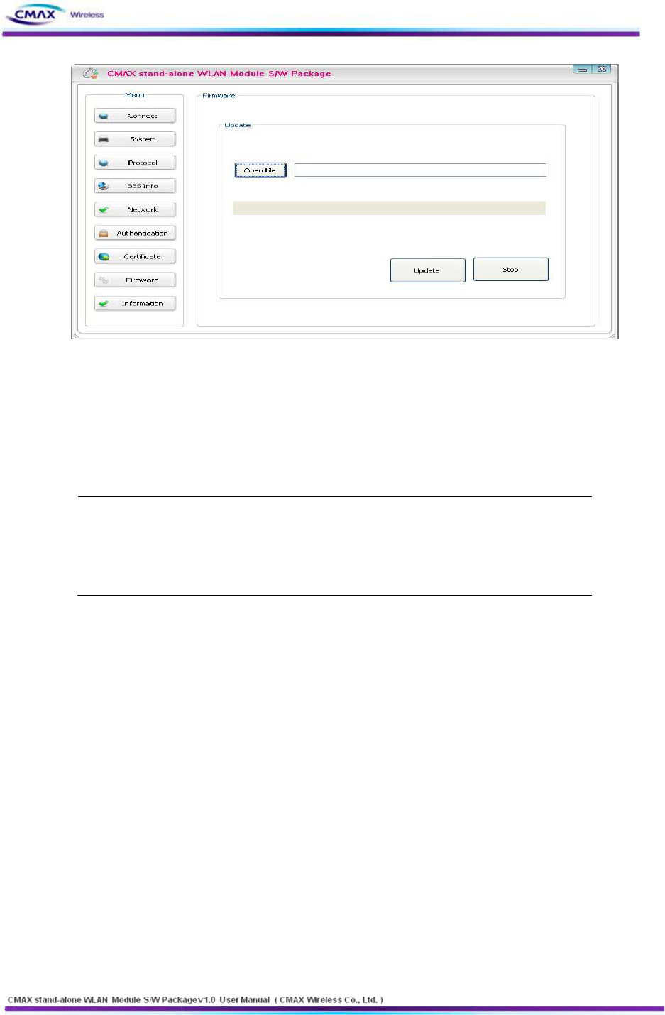
3.1.10 Firmware
: It has been supporting the firmware upgrade. If It does not connect from CMAX
Module, can not update the firmware. To stable firmware upgrade, we are not supported
doing all of the features. After updating the firmware, CMAX Module must be rebooted.
22
www.cmaxwireless.co.kr
[Figure 3.1.10.1] Upgrade Firmware
l Open file : Select a firmware type of [WLAN_M*.Bin]
l Update : Update a firmware to CMAX Module
l Stop : Stop the firmware upgraded
Note :
Emergency mode :
If an error occurs while firmware upgrade, CMAX module will be started to
the emergency mode. Emergency mode does not support the security
features. So You must update the full firmware to operate normal mode.
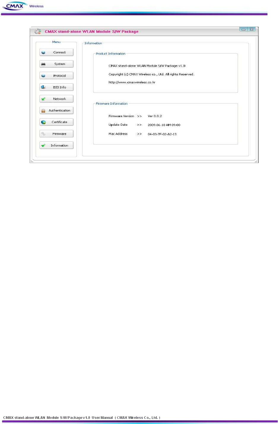
3.1.11 Information
: Product and firmware information is displayed
23
www.cmaxwireless.co.kr
[Figure 3.1.11.1] Information
l Product Information : Product name
l Firmware Version : Firmware version
l Update Date : Updated date
l Mac Address : CMAX Module’s Mac Address
3.2 Web Configuration
Set the CMAX Modules’s configuration through web connecting
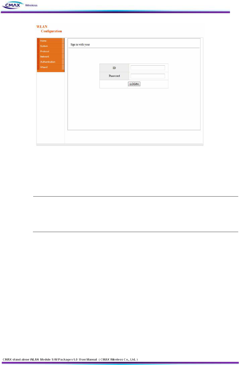
3.2.1 Web Connection
: CMAX Module can Set configuration using the HTTP, HTTPS protocol. HTTP and HTTPS
settings are same. Only, HTTPS secure connection is supported. Default setting is HTTP
l HTTP Connection : Start internet explorer through “http://192.168.192.168”
l Default : ID : admin Password : password
l
24
www.cmaxwireless.co.kr
[Figure 3.2.1.1] Sign in with your
l HTTPS Connection : Start internet explorer through https://192.168.1.1
l Default : ID : admin Password : password
Note : When establishing a HTTP connection, to continue to ignore security warnings.
l Web Server Security feature
- Supported the SSL 2.0, SSL 3.0 and TLS 1.0
- For HTTPS connections, if you want to access from the computer, security
protocol should be checked.
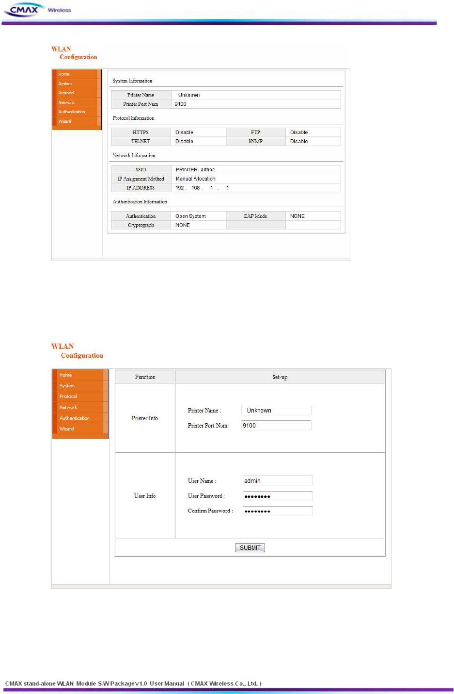
3.2.2 Home
: Display the system, protocol and network information in the CMAX Module
25
www.cmaxwireless.co.kr
[Figure 3.2.2.1] Home
3.2.3 System
: After inserting the [Pinter Name], [Printer Port], [User Name] and [User Password], user
should press the “SUBMIT” button to set system configuration
[Figure 3.2.3.1] System Setting
l Printer Name : Set the [Printer Name]
l Print Port Num : Set the [Print Port Number]
l User ID : Set the [User ID]
l User Password : Set the [User Password]
26
www.cmaxwireless.co.kr
l Confirm Password : Set correct values of [Confirm Password]
l Default : User ID : admin , User Password : password
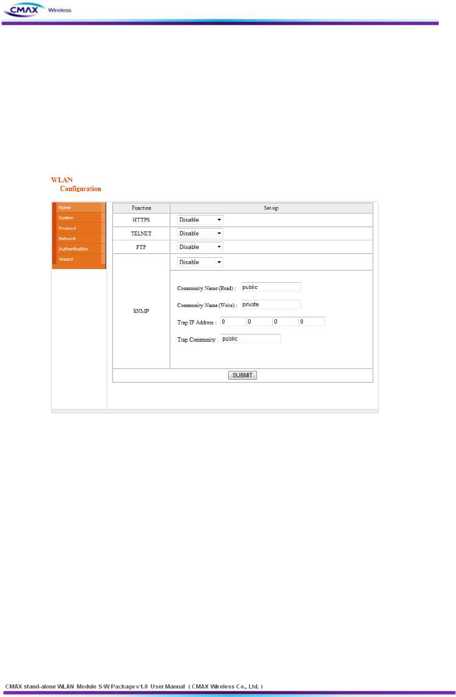
3.2.4 Protocol
: Set the HTTPS, TELNET, FTP and SNMP that are applications if you use. Then To perform
SNMP sets for each item. After inserting, user should press the “SUBMIT” button to set
Protocol configuration
[Figure 3.2.4.1] Protocol Setting
l Setup
- HTTPS (Default setting is HTTP)
- TELNET (Default setting is disable)
- FTP (Default is disable)
- SNMP (Default is disable)
l SNMP
- Community Name (Read) : Read Community
n Default : Public
- Community Name (Write) : Write Community
n Default : Private
- Trap IP Address : Trap IP Address.
n Default : 0.0.0.0
- Trap Community : Trap Community
n Default : Public
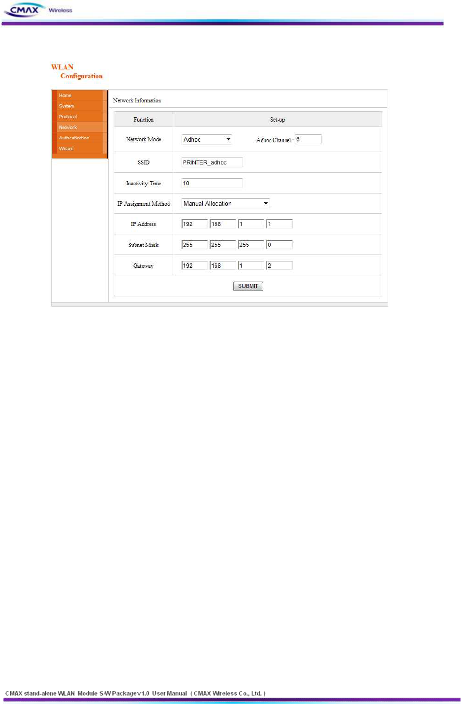
3.2.5 Network
27
www.cmaxwireless.co.kr
: After inserting the network configuration, user should press the “SUBMIT” button to set.
[Figure 3.2.5.1] Network Setting
l Network Mode : Select the Infra Network or Adhoc mode.
l Note : If adhoc mode user selects to connect a adhoc-channel (1~14).
l SSID : Set the SSID that user is going to connect. SSID Can set up maximum of 32
bytes.
l Inactivity Time : After connecting to the server of printer, It is time to maintain a
connection with the server. Default setting : Disable, Maximum time : 3600(sec)
l IP Assignment Method : Supported Automatic Allocation(DHCP Client) or Manual
Allocation. Default setting : Manual Allocation
l Automatic Allocation(DHCP Client) : Assigns the IP Address that is assigned in the DHCP
server automatically
l Manual Allocation : Does not assign the IP address in the AP(Access Point)’s DHCP server.
User should insert the IP Address that is such as IP Address of AP.
l IP Address : Insert the [IP Address] of AP : Default IP Address : 192.168.1.1
l Subnet Mask : Insert the [Subnet Mask] of AP : Default subnet Mask : 255.255.255.0
l Gateway : Insert the [Gateway] of AP : Default Gateway : 192.168.1.2
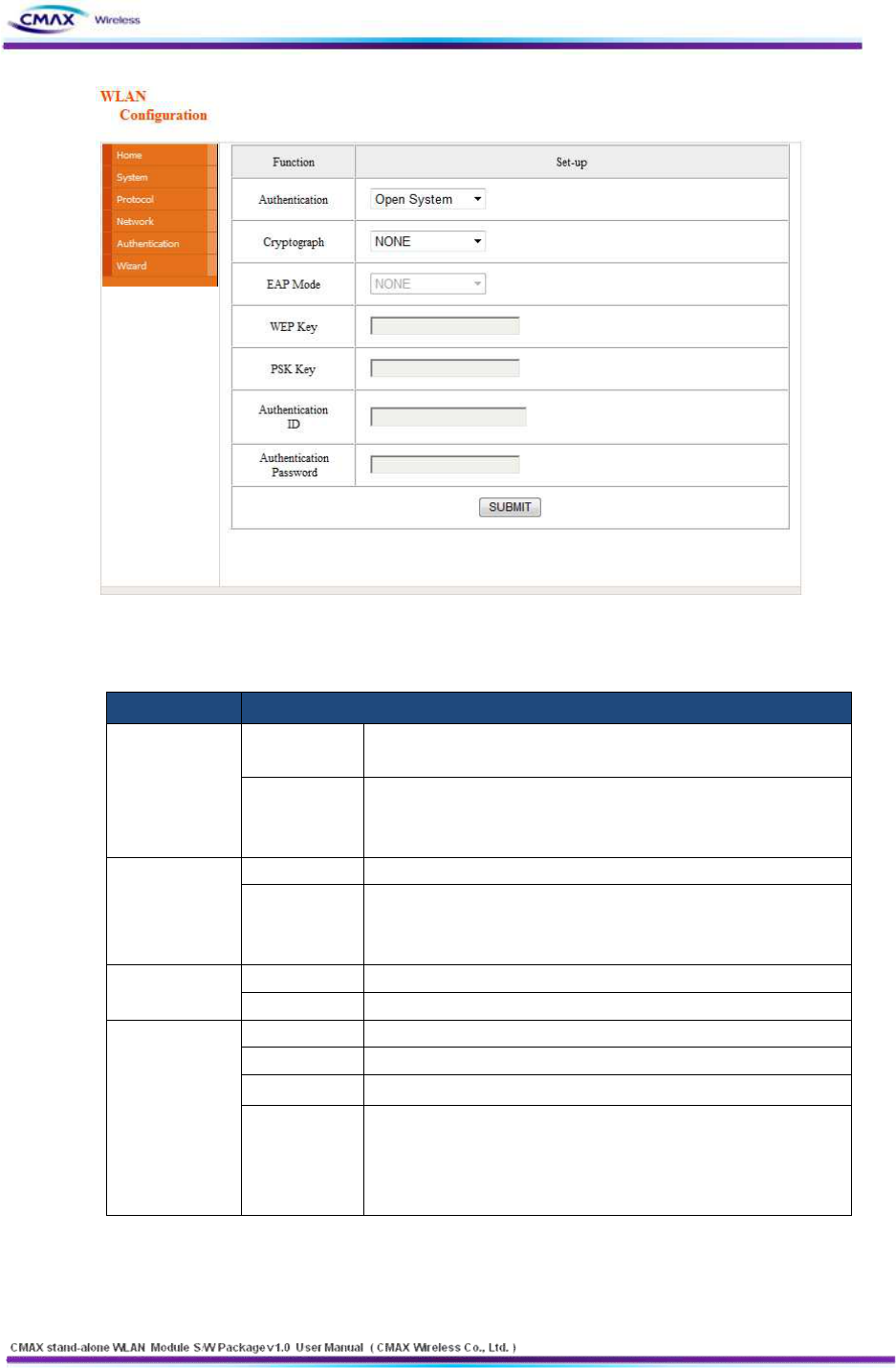
3.2.6 Authentication
: After inserting the security features, user should press the “SUBMIT” button
to apply on the system.
28
www.cmaxwireless.co.kr
[Figure 3.2.6.1] Authentication Setting
l Authentication : It is security configuration between CMAX Module and AP(Access Point)
FIELD
DESCRIPTION
Open System
Cryptograph
It should be select NONE or WEP64/128 as the setting of AP to
be access
WEP Key
You can input the max 26charater,. It Configure to WEPB64/18 if
you input it like the following format.
- WEP64 (5 ASCII, 10 HEX), WEP128 (13 ASCII, 26 HEX)
Shared Key
Cryptograph
Select a WEP64/128 same AP’s configuration to be access.
WEP Key
You can input the max 26charater,. It Configure to WEPB64/18 if
you input it like the following format.
- WEP64 (5 ASCII, 10 HEX), WEP128 (13 ASCII, 26 HEX)
WPA-PSK /
WPA2-PSK
Cryptograph
You should same to configure a TKIP/AES with AP to be access.
PSK Key
You should same to input a TKIP/AES with AP to be access.
WPA-TKIP /
WPA2-AES
Cryptograph
You should same to configure a cryptograph with AP to be access.
EAP
You should same to configure a EAP Mode with AP to be access.
ID
You should Input the ID with configured certificate Server
Password
You should Input the Password with configured certificate Server
However, If EAP Configuration is a EAP-TLS, you should input the
private_key_password that is certificate password that generated
for CMAX module.
[Table 3.2.6.2] Security setting
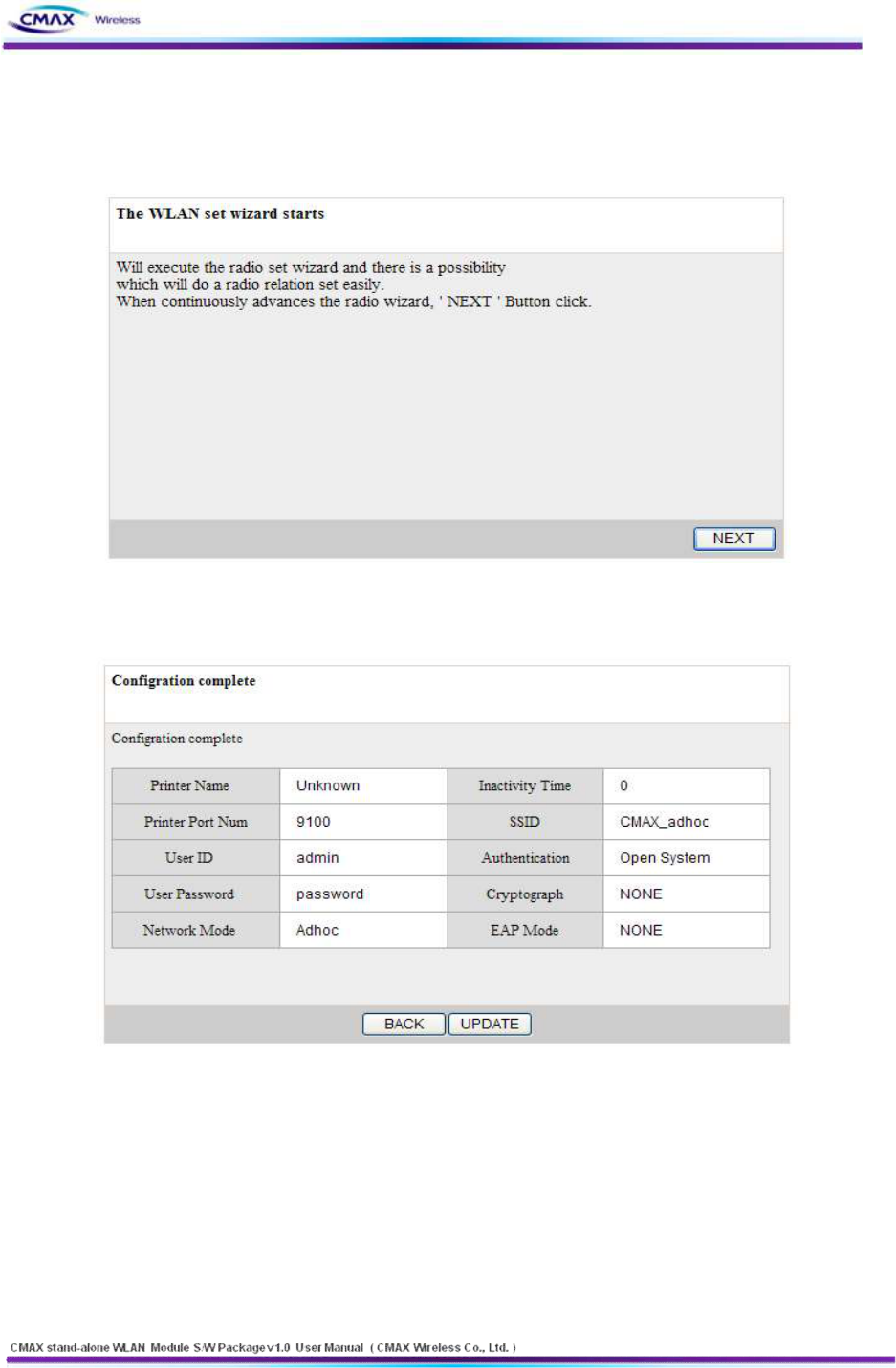
3.2.7 Wizard
29
www.cmaxwireless.co.kr
: Provides that user can easily insert the configuration of system. After inserting the
configurations, user should press the “NEXT” button to apply on the system.
[Figure 3.2.7.1] Wizard start page
[Figure 3.2.7.2] Wizard result page
30
www.cmaxwireless.co.kr
3.3 TELNET
You can configure the CMAX module by TELNET
Note :
TELNET : TELNET is Text-based remote access service and based TCP/IP Protocol.
CMAX module configuration : Input the number provided on the left side of the menu and
then enter the "Enter" to enter the next entry.
Menu move example
l Menu number : move to next menu.
l $ : go to the previous menu.
l # : Go to the main menu.
3.3.1 TELNET Connection
: Connect by Telnet Client.( Microsoft Windows xp based on the description.)
l Windows command execution.
- Windows’s Beginning – Run – input “command”.
n Input “TELNET 192.168.1.1 (IP Address of CMAX module)” to command windows.
Default : IP Address : 192.168.1.1
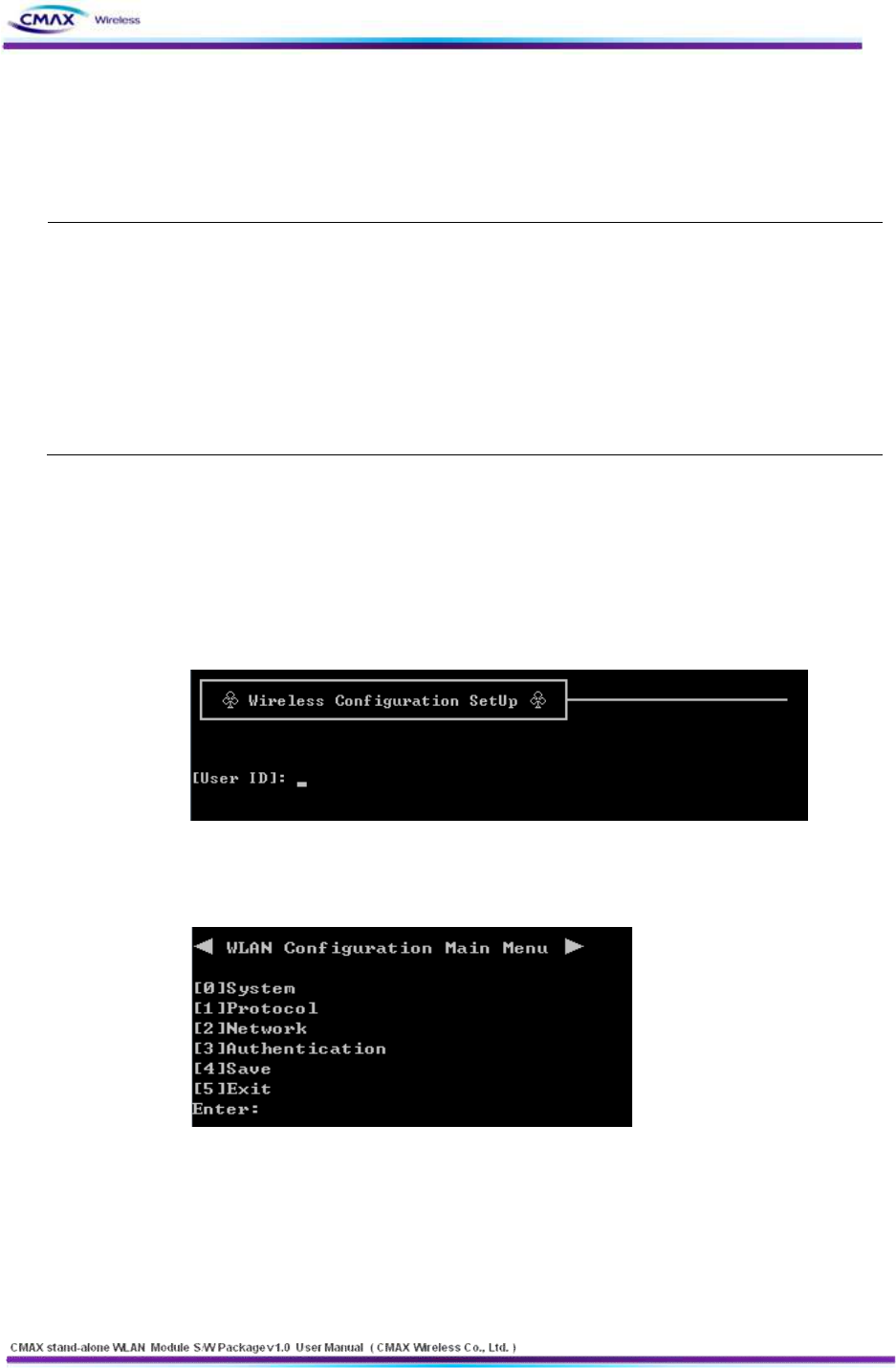
[Figure 3.3.1.1] TELNET Configuration Server Connection Screen
- Input “User ID, User Password” and then enter the “Enter”
n Default : User ID : admin User Password : password
[Figure 3.3.1.2] TELNET Configuration major menu
l [1] System: Configure System information.
l [2] Protocol: You can select to Enable(1) or disable(0) the application of the activities.
l And configure SNMP access information. (Default setting HTTP)
l [2] Protocol: You can select to Enable(1) or disable(0) the application of the activities. And
configure SNMP access information. (Default setting HTTP)
31
www.cmaxwireless.co.kr
l Network: Configure Network parameter of CMAX module.
l Authentication: Configure security parameter of CMAX module.
l Save: You can store the configuration information that input so far to the CMAX module
l Exit : Terminate TELNET connection.
3.3.2 System
: You can configure Printer Name, Print Port Number, ID and User Password. User ID and
User Password is applied to all application of CMAX module.
l Select “[1]System” to “configuration main menu”.
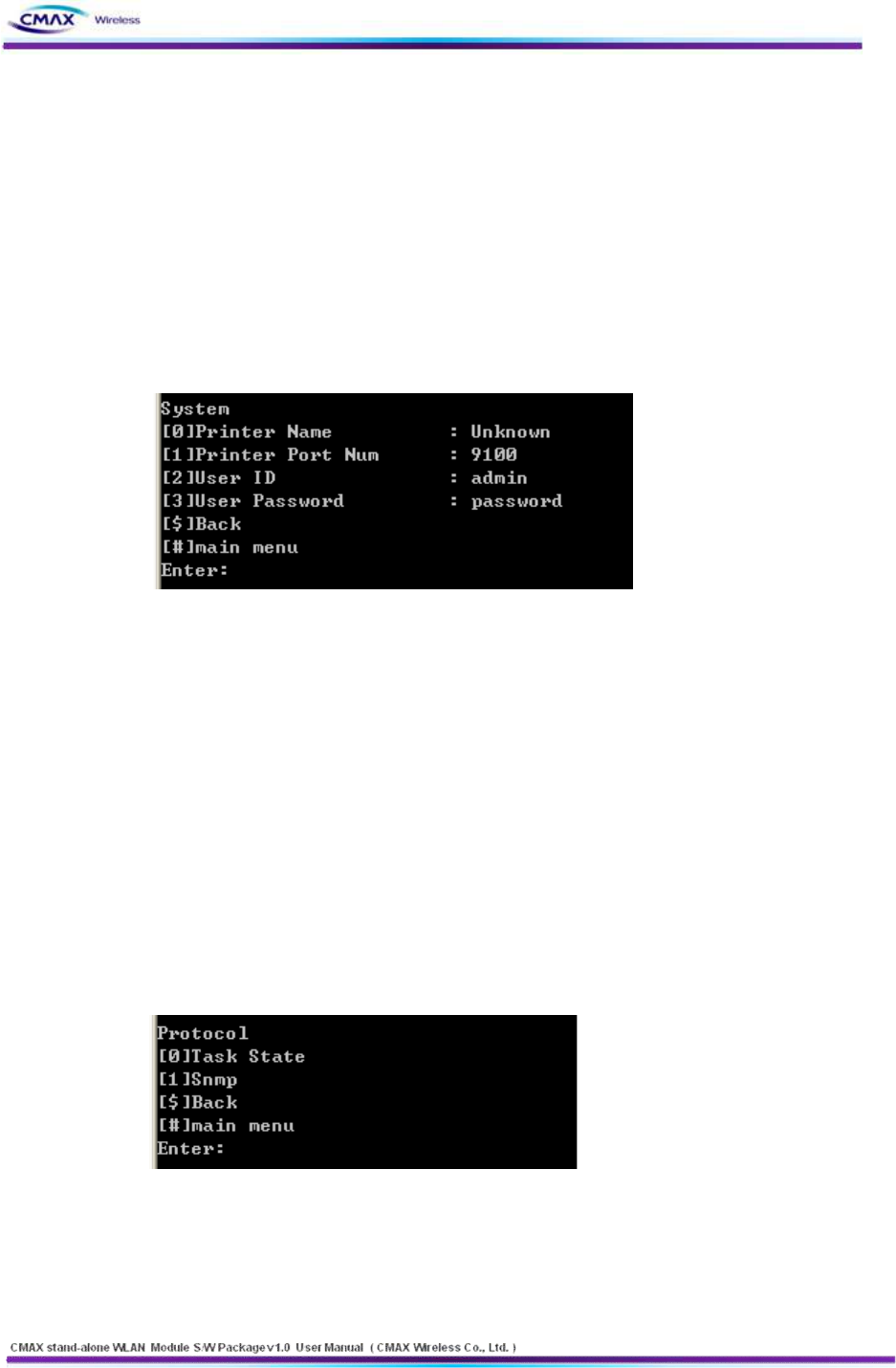
[Figure 3.3.2.1] TELNET System information menu
l [0] System Name : Configure CMAX Module name
l [1] TCP Server Port Num: Configure TCP Server port number.
l [2] User ID: Configure user ID.
l [3] User Password : Configure user password.
l [$] Back: Go to the previous menu.
l [#] Main Menu : Go to the main menu.
3.3.3 Protocol
: You can select to enable or disable the application(HTTP, HTTPS, TELNET, FTP, SNMP) of
the use and configure SNMP Parameter(Community, Trap IP Address, Trap Community).
l Select [2]Protocol to “Configuration main menu.”
[Figure 3.3.3.1] TELNET Protocol menu
32
www.cmaxwireless.co.kr
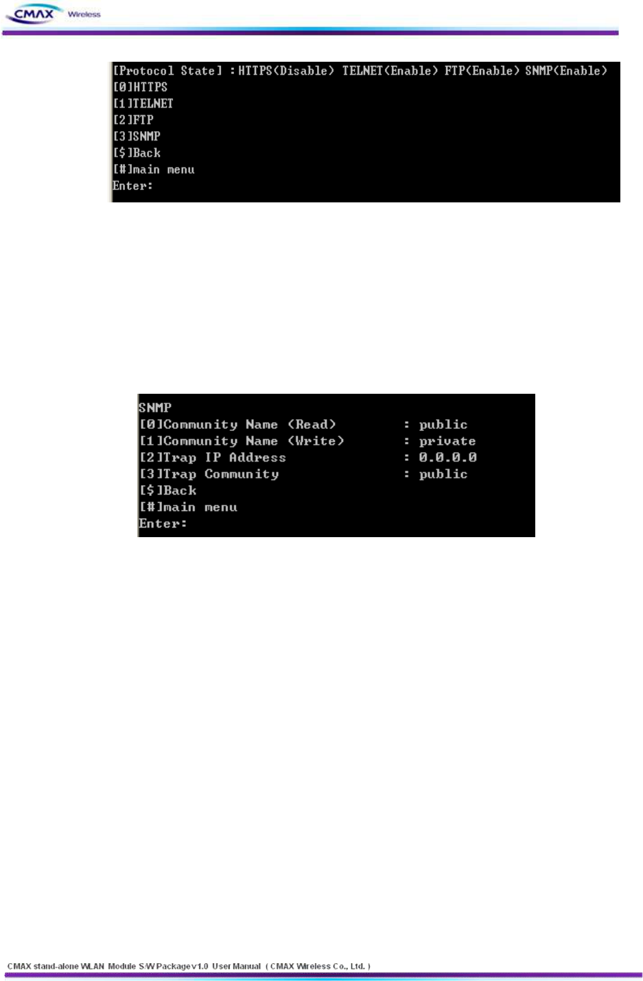
[Figure 3.3.3.2] TELNET Task State Protocol menu
l Select “[0]Task State” to “Protocol menu.”
n [0] HTTPS : Configure to Enable(1) or Disable(0) to HTTPS. ( default HTTP )
n [1] TELNET : Configure to Enable(1)/Disable(0) to TELNET.
n [2] FTP : Configure to Enable(1)/Disable(0) to FTP
n [3] SNMP : Configure to Enable(1)/Disable(0) to SNMP.
[Figure 3.3.3.3] TELNET SNMP Connection Information menu
l Select “[1] SNMP” to Protocol menu.
n [0] Community Name (Read) :If SNMP is Enable(1) state, you can configure to
accessed community of read mode..
n [1] Community Name (Write) : If SNMP is Enable(1) state, you can configure to
accessed community of write mode.
n [2] Trap IP Address : If SNMP is Enable(1) state, you can configure to IP Address that
received Trap message.
n [3] Trap Community : If SNMP is Enable(1) state, you can configure to Trap
community.
n [$] Back: Go to the previous menu.
n [#] Main Menu : Go to the main menu.
3.3.4 Network
: Configure Network parameter of CMAX module.
l Select “[3] Network” to Configuration main menu.
33
www.cmaxwireless.co.kr
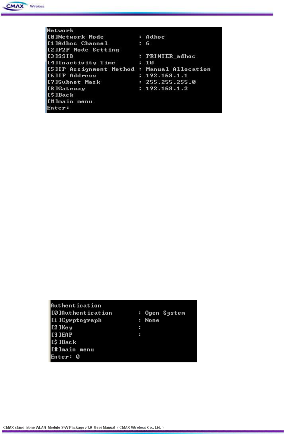
[Figure 3.3.4.1] TELNET Network menu
l [0] Network Mode : Select a network mode( Infra Network(0) / Adhoc(1) / P2P(2)).
l [1] Adhoc Channel : Configure Adhoc Channel(1~14) to Connection.
l [2] SSID : It should be configured the SSID same as AP's SSID to be access.
l [3] Inactivity Time : It means a time limit keeping connection that without data
communication between client and server.
l [4] IP Assignment Method : Select IP Assignment method( DHCP(0)/Manual
Alloccation(1) ).
l [5] IP Address : If you selected Manual Alloccation(1), configure IP Address.
l [6] Subnet Mask : If you selected Manual Alloccation(1), configure Subnet Mask.
l [7] Gateway : If you selected Manual Alloccation(1), configure Gateway.
l [$] Back: Go to the previous menu.
l [#] Main Menu : Go to the main menu.
3.3.5 Authentication
: Configure CMAX Module Security. It should be configured the Security same as AP's
Security to be access.
l Select “[4]Authentication” to “configuration main menu”.
[Figure 3.3.5.1] TELNET Security main menu
l [0] Authentication : You configure a security method.. Reference [Table 2.2.1.6.1]
l [1] Cryptograph : Configure an encryption method according to security methods.
l [2] Key : Configure a key of WEP or PSK.
l [3] EAP : Configure an EAP Mode according to WPA/WPA2
34
www.cmaxwireless.co.kr
l [$] Back: Go to the previous menu.
l [#] Main Menu : Go to the main menu.
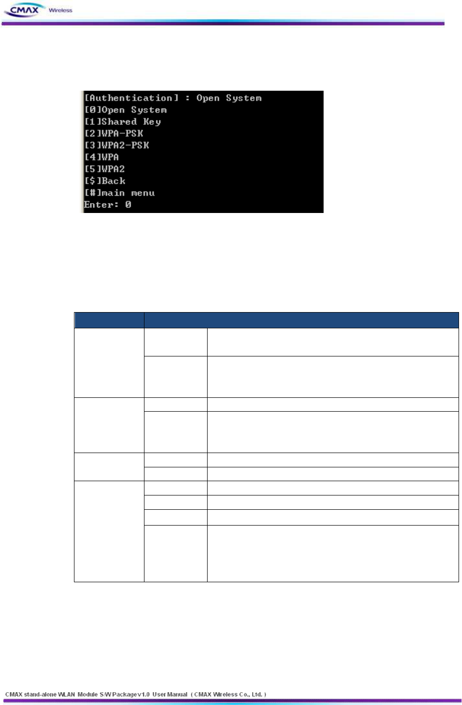
[Figure 3.3.5.2] TELNET Open System Security main menu
l [0~5] Authentication : Configure a Security Mode. Reference [Table 2.2.1.6.1]
l [$] Back: Go to the previous menu.
l [#] Main Menu : Go to the main menu.
l “Authentication" is a function that CMAX module does authenticate to AP through to
wireless
FIELD
DESCRIPTION
Open System
Cryptograph
It should be select NONE or WEP64/128 as the setting of AP to
be access
WEP Key
You can input the max 26charater,. It Configure to WEPB64/18 if
you input it like the following format.
- WEP64 (5 ASCII, 10 HEX), WEP128 (13 ASCII, 26 HEX)
Shared Key
Cryptograph
Select a WEP64/128 same AP’s configuration to be access.
WEP Key
You can input the max 26charater,. It Configure to WEPB64/18 if
you input it like the following format.
- WEP64 (5 ASCII, 10 HEX), WEP128 (13 ASCII, 26 HEX)
WPA-PSK /
WPA2-PSK
Cryptograph
You should same to configure a TKIP/AES with AP to be access.
PSK Key
You should same to input a TKIP/AES with AP to be access.
WPA-TKIP /
WPA2-AES
Cryptograph
You should same to configure a cryptograph with AP to be access.
EAP
You should same to configure a EAP Mode with AP to be access.
ID
You should Input the ID with configured certificate Server
Password
You should Input the Password with configured certificate Server
However, If EAP Configuration is a EAP-TLS, you should input the
private_key_password that is certificate password that generated
for CMAX module.
[Table 3.3.5.1] Security setting
35
www.cmaxwireless.co.kr
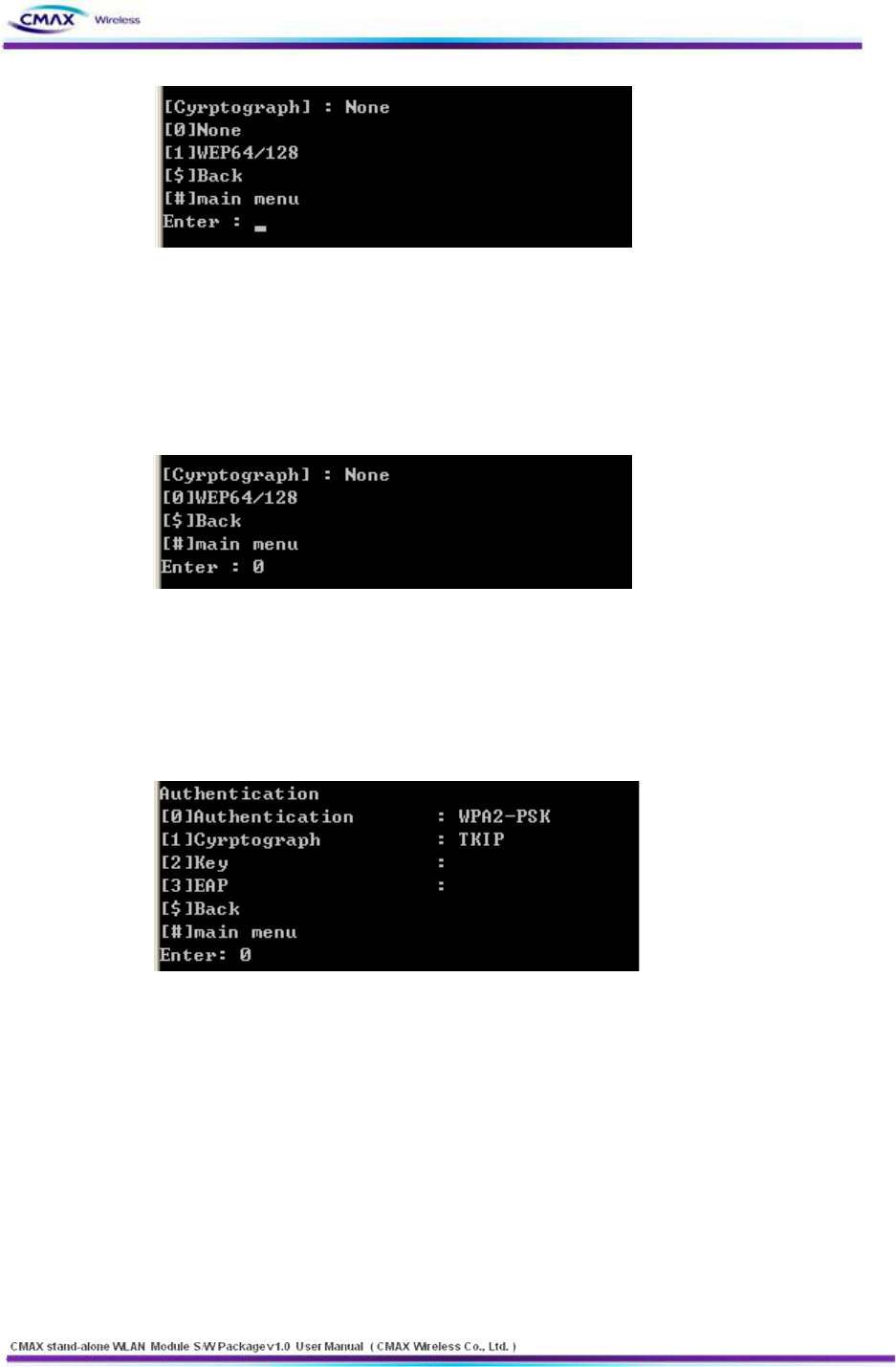
[Figure 3.3.5.3] TELNET Open System Cryptograph menu
l [0] Open System : You should select ‘NONE[0]’ or ‘WEP64/128[1]’
l [$] Back: Go to the previous menu.
l [#] Main Menu : Go to the main menu.
[Figure 3.3.5.4] TELNET Shared Key Crypto graph menu
l [1] Shared Key : You should select ‘WEP64’ or ‘WEP128’
l [$] Back: Go to the previous menu.
l [#] Main Menu : Go to the main menu.
[Figure 3.3.5.5]TELNET WPA-PSK/WPA2-PSK a detailed menu.
l [0] Authentication : you should configure a authentication mode. reference [Table
2.2.1.6.1]
l [1] Cryptograph : You should configure a Cryptograph mode according to authentication
mode
l [2] Key : You should a WEP key of PSK Key.
l [3] EAP : You should configure a EAP Mode according to WAP/WAP2
l [$] Back: Go to the previous menu.
l [#] Main Menu : Go to the main menu.
36
www.cmaxwireless.co.kr
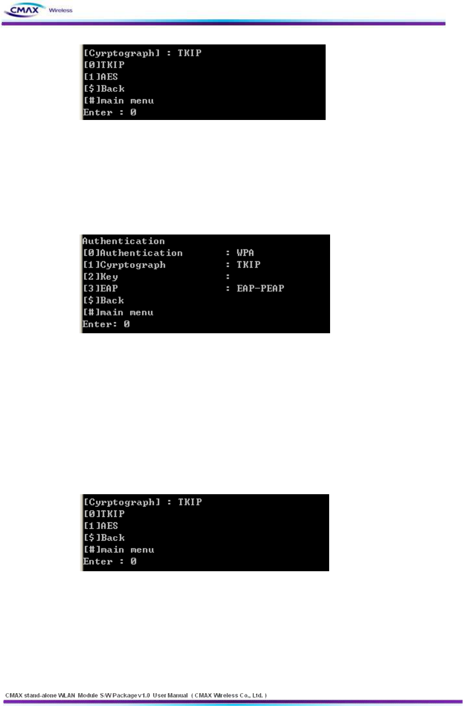
[Figure 3.3.5.6] TELNET WPA-PSK/WPA2-PSK Cryptograph menu
l [2] WPA-PSK : You should select a ‘TKIP[0]’ or ‘AES[1]’
l [3] WPA2-PSK : You should select a ‘TKIP[0]’ or ‘AES[1]’
l [$] Back: Go to the previous menu.
l [#] Main Menu : Go to the main menu.
[Figure 3.3.5.7]TELNET WPA/WPA2 a detailed menu.
l [0] Authentication : You should configure a authentication method. Reference [Table
2.2.1.6.1]
l [1] Cryptograph : Configure an encryption method according to security methods.
l [2] Key : Configure a key of WEP or PSK.
l [3] EAP : Configure an EAP Mode according to WPA/WPA2
l [$] Back: Go to the previous menu.
l [#] Main Menu : Go to the main menu.
[Figure 2.2.3.5.8 ]TELNET WPA/WPA2 Cryptograph menu
l Cryptograph : It should be configured a cryptograph method with ‘TKIP[0]’ or ‘AES[1]’
l [$] Back: Go to the previous menu.
l [#] Main Menu : Go to the main menu.
37
www.cmaxwireless.co.kr
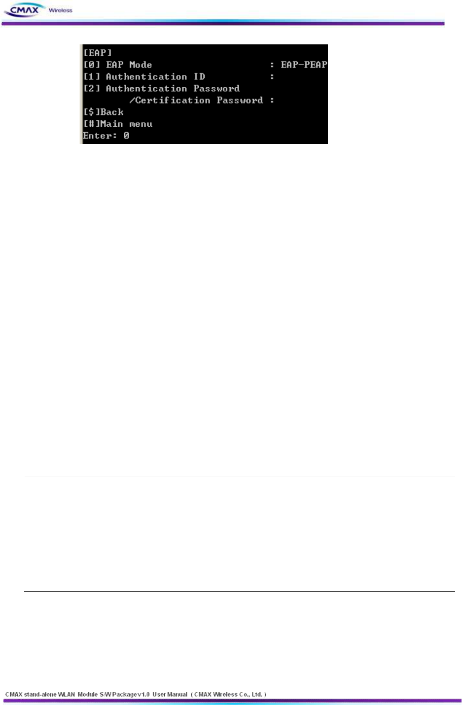
[Figure 3.3.5.9] TELNET EAP Configuration Menu.
l [0] EAP Mode: It should be selected same as AP’s EAP mode
l [1] EAP ID/PASSWORD: it should be configured same as AP’s EAP ID and password.
l [$] Back: Go to the previous menu.
l [#] Main Menu : Go to the main menu.
3.3.6 Save
: To save a changed configuration information on CMAX module, select the ‘[5]Save’ in
the configuration main menu.
3.3.7 Exit
: To terminate a TELNET connection, select the ‘[6] Exit’ in the configuration main menu.
3.4 FTP
It is function to Upload or Download 'Configuration file' for CMAX module configuration by
FTP. If you modify the 'Configuration file' and upload that, it will be changed CMAX module
setup.
Note :
FTP : File Transfer Protocol (FTP) is a standard network protocol used to exchange and
manipulate files over a TCP/IP-based network(between server and client).
Supported FTP command
l ls : List contents of remote directory
l Get: : Receive configuration file
l Put : Send configuration file
CAUTION : To Upload a file, don’t use file-extension and use “config” to filename.
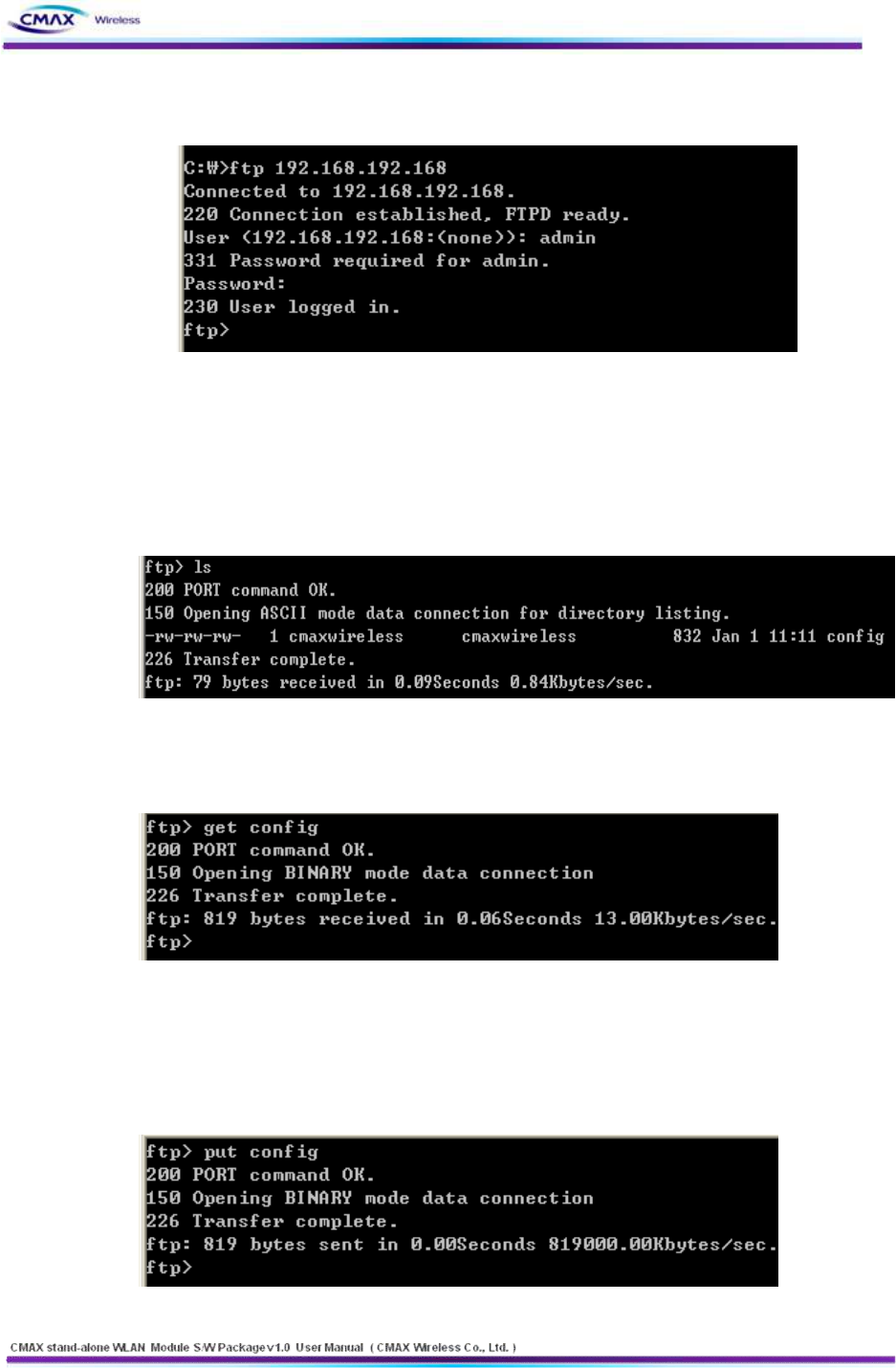
3.4.1 FTP Connection
: It should be executed to Microsoft Windows xp Command line.
l Execute Windows command
- Microsoft Windows xp’s beginning – run – input ‘command’
38
www.cmaxwireless.co.kr
- It should be input command ‘FTP 192.168.1.1 (CMAX module’s IP Address)’
n Default : IP Address : 192.168.1.1
[Figure 3.4.1.1] FTP Connection Screen
- It should be input User ID and User password.
n Default : User ID : admin User Password : password
3.4.2 Configuration File list view
: It should be confirmed a file as you input ‘ls’.
[Figure 3.4.2.1] FTP ‘ls’ command executed screen
3.4.3 Configuration File download
:It should be downloaded a file as you input ‘get config’.
[Figure 3.4.3.1] FTP ‘get config’ command screen
3.4.4 Configuration File Upload
: It should be uploaded a file as you input ‘put config’. you must use file name as
‘config’.
[Figure 3.4.4.1] FTP ‘put config’ command screen
39
www.cmaxwireless.co.kr
3.4.5 Configuration File Specification
: Table 3.4.5.1 is downloaded file’s content from CMAX module by ‘get config’
command. To change a configuration value, input without blank in ‘bracket’([ ]).
** Caution!!!
** Do not change the order or contents of the menu.
** Only need to change the settings, please.
[1] System
1. Printer Name: [unknown]
2. Printer Port Num: [9100]
3. User ID: [admin]
4. User Password: [password]
[2] Protocol
1. Task State
1) HTTPS: [0]
2) TELNET: [0]
3) FTP: [0]
4) SNMP: [0]
2. SNMP
1) Community Name (Read): [public]
2) Community Name (Write): [private]
3) Trap IP Address: [0.0.0.0]
4) Trap Community: [public]
[3] Network
1. Network Mode
1) Infra Network(0) / Adhoc(1) / P2P(2): [1]
2) Adhoc Channel: [1]
2. SSID: [PRINTER_adhoc]
3. Inactivity Time: [0]
4. IP Assignment Method: [1]
5. IP Address: [192.168.1.1]
6. SubnetMask: [255.255.255.0]
7. Gateway: [192.168.1.2]
[4] Authentication
1. Authentication: [0]
2. Cryptograph: [0]
3. EAP Mode: [0]
4. WEP Key: []
5. PSK Key: []
6. Authentication ID: []
7. Authentication Password: []
[Table 3.4.5.1] FTP ‘config’ file’s content

40
www.cmaxwireless.co.kr
l Describes in detail how the file should be configure.
[1] System: Configure the system information.
1. Printer Name: Configure the system name.
2. Printer Port Num: Configure the TCP server port.
3. User ID: Configure the user ID.
4. User Password: Configure the user password.
[2] Protocol: Configure the Application (HTTPS, TELNET, FTP, SNMP) as Enable(1) or Disable(0).
And configure the SNMP connect information.
1. Task State
1) HTTPS: Configure the HTTPS as Enable(1) or Disable(0).(default configuration is HTTP)
2) TELNET: Configure the TELNET as Enable(1) as Disable(0).
3) FTP: Configure the FTP as Enable(1) as Disable(0).
4) SNMP: Configure the SNMP as Enable(1) or Disable(0).
2. SNMP
1) Community Name (Read): Configure the Read mode community..
2) Community Name (Write): Configure the Write mode community.
3) Trap IP Address: If SNMP’s state is Enable(1), Configure the IP address for
Trap message received.
4) Trap Community: If SNMP’s state is Enable(1), Configure the Trap community.
[3] Network: Configure the CMAX module’s Network parameter.
1. Network Mode
1) Infra network(0) / Adhoc(1) : Select a network mode to connect
2) Adhoc Channel: If you selected Adhoc, you select channel(1~11) .
2. SSID: CMAX_adhoc: It should be input SSID as the setting of AP to be access
3. Inactivity Time: It should be configured a time limit keeping connection that without
data communication between client and server.
4. IP Assignment Method: Select DHCP(0) or Manual Allocation(1)
5. IP Address: If you selected Manual Allocation(1), you configure a IP Address.
6. SubnetMask: If you selected Manual Allocation(1), you configure a Subnet Mask.
7. Gateway: If you selected Manual Allocation(1), you configure a Gateway.
[4] Authentication: It should be configured the Security same as AP's Security to be access.
1. Authentication: Open System(0), Shared Key(1), WPA-PSK(2), WPA-PSK2(3), WPA(4),
WPA2(5)
2. Cryptograph: NONE(0), WEP64/128(1), TKIP(2), AES(3)
3. EAP Mode: EAP-PEAP(0), EAP-TTLS(1), EAP-TLS(2), EAP-LEAP(3)
4. WEP Key: It should be configure the WEB key same as AP’s WEP key.
5. PSK Key: It should be configure the PSK key same as AP’s PSK key.

41
www.cmaxwireless.co.kr
6. Authentication ID: It should be configure the Authentication ID same as AP’s
Authentication ID.
7. Authentication Password: It should be configured the Authentication password same as
AP's Authentication password to be access.
3.5 SNMP
It is managed a network information through SNMP (supported SNMPv1).
Note :
SNMP stands for 'Simple Network Management Protocol' and it is used for network
management.
SNMP is only a protocol to transfer messages so it need the Application program to get Network
management information using SNMP. SNMP has SNMP manager and agent, as in common network
application is composed server and client model. SNMP agent is a part of SNMP module and it is
installed in managed system to collect the network or system information. SNMP manager is also part
of the SNMP module and it request the network information to SNMP agent.
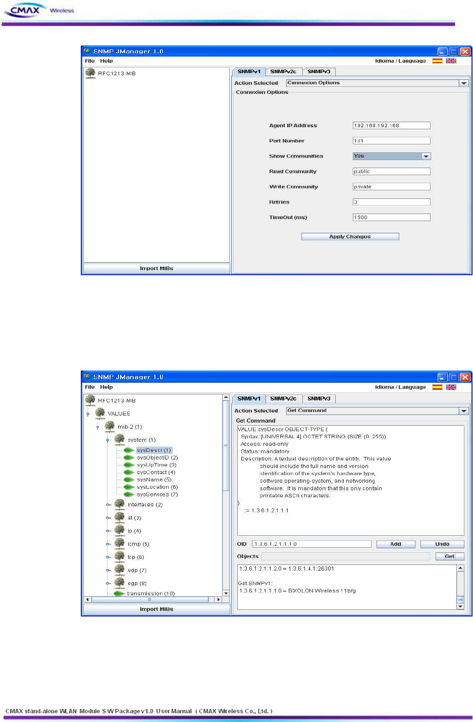
3.5.1 SNMP Connection
: It should be connect a SNMP Agent through SNMP Manager. It is introduced a SNMP
operation at this manual as used SNMP-JManger-v1.0.
l SNMP-JManager-v1.0 running
- Input the address(192.168.1.1 , CMAX module’s IP Address) to ‘Agent IP Address’.
n Default : IP Address : 192.168.1.1
- Input the Read Community, Write Community and then click “Apply Changes” button.
n Default : Read Community : public Write Community : private
42
www.cmaxwireless.co.kr
[Figure 3.5.1.1] SNMP Connection configuration screen
3.5.2 SNMP Manager operation test: it is description of basic SNMP operation.
l If you selected terminal node to ‘Get Tree’, get this value(client note value).
[Figure 3.5.2.1] SNMP ‘get’ message operation screen
43
www.cmaxwireless.co.kr
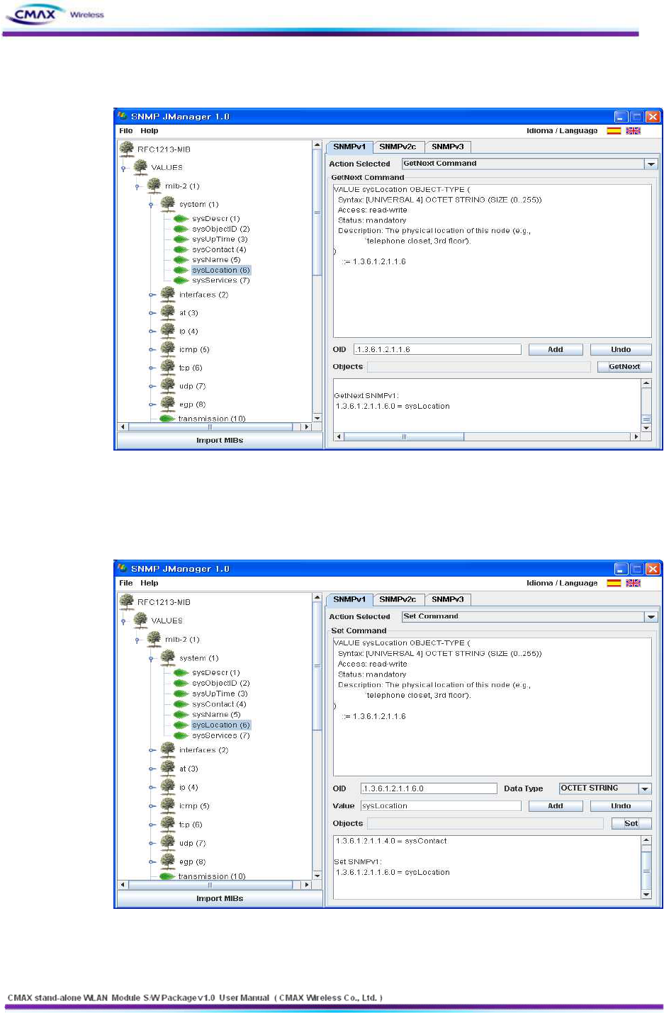
l Get Next : You can bring the value at trees as selected a terminal node.
[Figure 3.5.2.2] SNMP ‘getnext’ message operation screen
l You can configure the terminal node value to ‘set tree’. (You can set only the contents
had set on "Write")
[Figure 3.5.2.3] SNMP ‘set’ message operation screen
44
www.cmaxwireless.co.kr
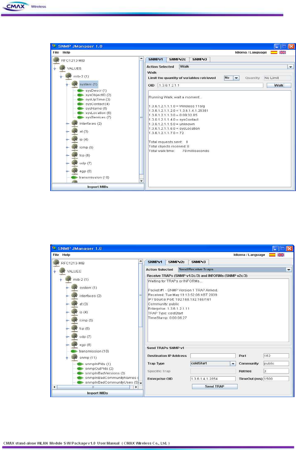
n Walk: It can get the all item that terminal node of tree or terminal node of node.
[Figure 3.5.2.4] SNMP ‘walk’ message operation screen
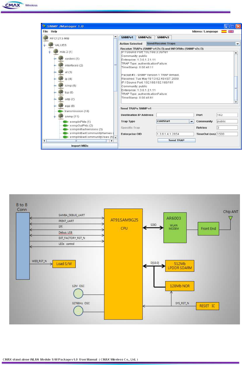
n Traps: If a specific event occurs, relevant(in the event) message is transmitted to trap address.
- ColdStart: when a terminal rebooting works, coldstart message is transmitted to trap
address.
[Figure 3.5.2.5] SNMP coldStart message received screen
- AuthenticationFailure: If ‘Read’, ‘Write’ Community is not correct, AuthenticationFailure
message is transmitted to trap address.
45
www.cmaxwireless.co.kr
[Figure 3.5.2.6] SNMP AuthenticationFailure message received screen
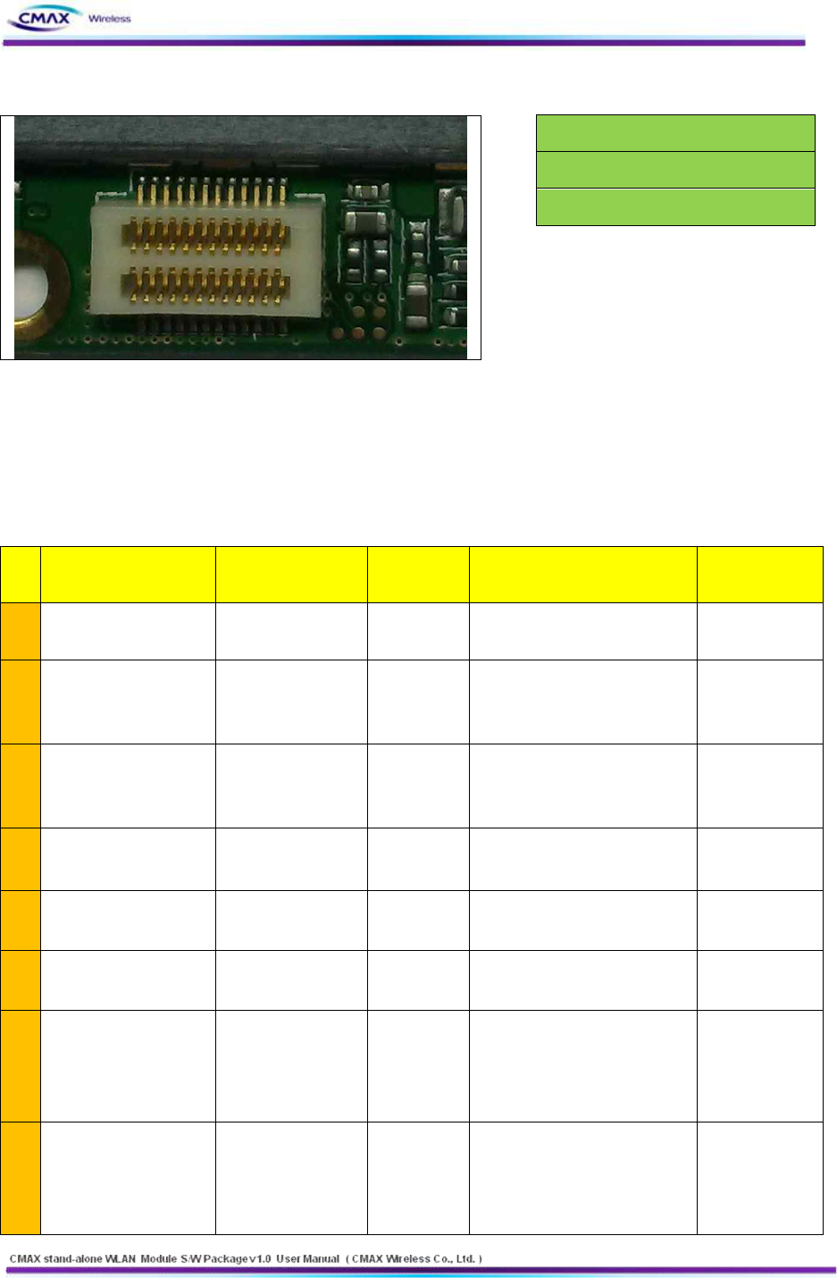
4. Hardware Block Diagram
[Figure 4.1] Hardware Block Diagram
46
www.cmaxwireless.co.kr
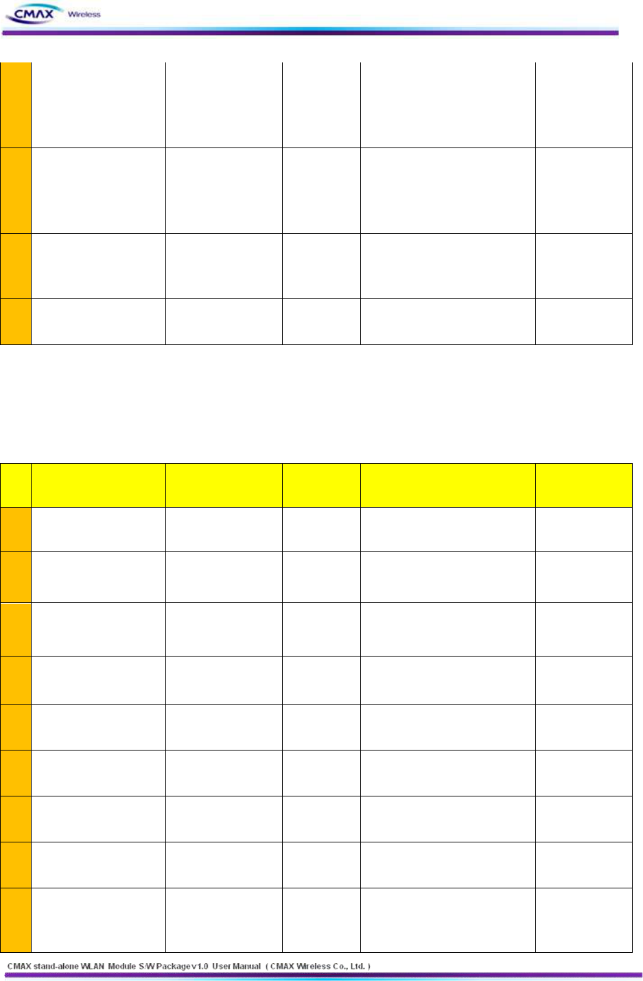
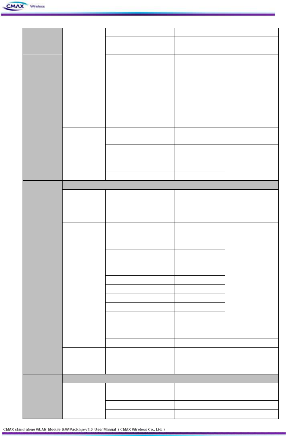
4.1 Hardware Pin Array
Pin
No
신호명
신호방향
전압 Level
기능
비고
1
DGND
GND
3
USB_DM
J 보드 ↔ W 보드
USB D- 신호
W 보드 CPU F/W
업데이트용
5
USB_DP
J 보드 ↔ W 보드
USB D+ 신호
W 보드 CPU F/W
업데이트용
7
DGND
GND
9
LED_GREEN
B 보드 ← W 보드
3.3V
green LED 동작신호
High active
11
LED_YELLOW
B 보드 ← W 보드
3.3V
yellow LED 동작신호
High active
13
SPI_MISO
B 보드 → W 보드
3.3V
SPI Master input Slave
output
B 보드 : SPI
slave mode
W 보드 : SPI
master mode
15
SPI_CLK
B 보드 ← W 보드
3.3V
SPI Clock
B 보드 : SPI
slave mode
W 보드 : SPI
master mode
BIXOLON 보드 (=B 보드)
WIDI 보드 (=W 보드)
WIDI BB_JIG 보드 (=J 보드)
47
www.cmaxwireless.co.kr
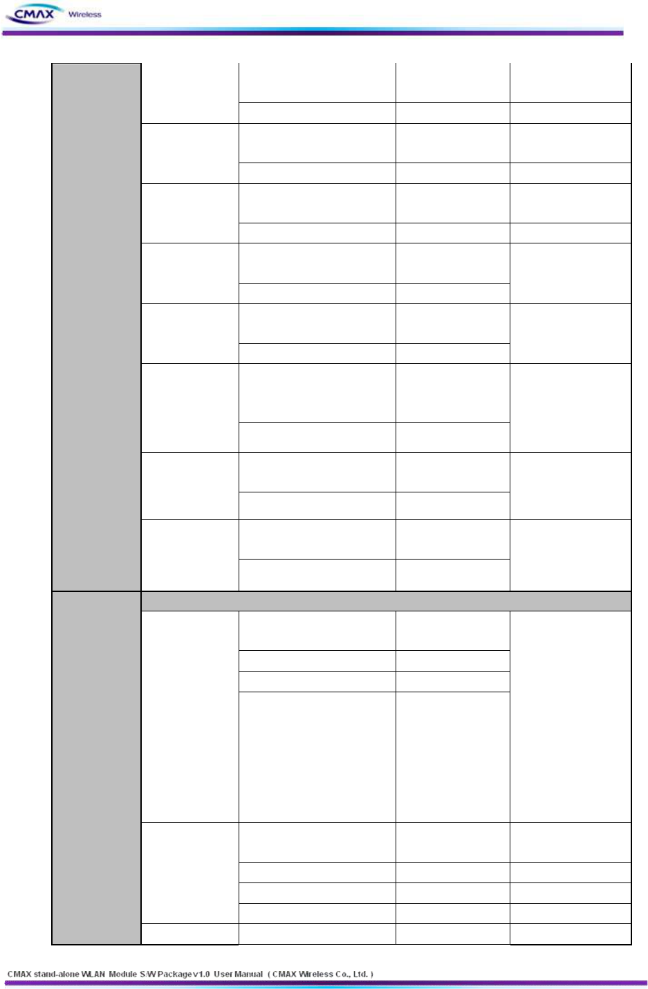
17
SPI_CS_N
B 보드 ← W 보드
3.3V
SPI Chip select
Low active
B 보드 : SPI
slave mode
W 보드 : SPI
master mode
19
SPI_MOSI
B 보드 ← W 보드
3.3V
SPI Master output Slave
input
B 보드 : SPI
slave mode
W 보드 : SPI
master mode
21
SAMBA_DEBUG_TXD
J 보드 ← W 보드
GND
W 보드 CPU Debug 용
UART
Transmit Data
23
DGND
GND
Pin
No
신호명
신호방향
전압 Level
기능
비고
2
VDD_3V3
B 보드 → W 보드
3.3V
W 보드 입력전원
4
VDD_3V3
B 보드 → W 보드
3.3V
W 보드 입력전원
6
WIDI_RST_N
B 보드 → W 보드
3.3V
W 보드 system RESET 신호
Low active
8
LED_RED
B 보드 ← W 보드
3.3V
red LED 동작신호
High active
10
CPU_CTS
B 보드 ← W 보드
3.3V
UART Clear To Send
12
CPU_RXD
B 보드 → W 보드
3.3V
UART Receive data
14
CPU_TXD
B 보드 ← W 보드
3.3V
UART Transmit Data
16
CPU_RTS
B 보드 → W 보드
3.3V
UART Request To Send
18
SAMBA_DEBUG_RXD
J 보드 → W 보드
GND
W 보드 CPU Debug 용
UART
Receive Data

48
www.cmaxwireless.co.kr
20
SPI_UART/_SEL
B 보드 → W 보드
3.3V
Low : UART 통신
High : SPI 통신
22
EXT_FACTORY_RST_N
B 보드 → W 보드
3.3V
WIDI 보드 Factory reset
Low active 신호
24
DGND
GND
5. Demo and Test
This chapter explains several examples that it can be used for functional testing of CMAX module.
Test environment is as follows.
5.1 Test environment
5.1.1 Hardware
l RS232 serial port with a PC
l CMAX module & CMAX test board
l PC's COM port and CMAX for the module's serial port to connect the serial cable is required.
5.1.2 Software
l Configuration Tool of CMAX module
l Hyper Terminal( or other Terminal program)
5.2 Start Test
5.2.1 STEP1.
l It should be connect to CMAX Test board and PC’s Serial port.
l It should be turn on the CMAX test board.
l It should be connected the PC to CMAX module through serial interface.
l It should be run a Terminal program of PC by connected Serial(ex, HyperTerminal)
5.2.2 STEP2. (Wireless Configuration to between CMAX module and PC).
l It should be connected the PC to CMAX module through wireless LAN.
l It should be configured the PC’s Network to next value. IP( 192.168.1.XXX),
subnet(255.255.255.0), gateway(192.168.1.2)
l It should be confirmed wireless connection of CMAX module and PC by Ping response.
5.2.3 STEP3. (Data Transfer)
l It should be run a Terminal program of PC by connected WLAN(ex, HyperTerminal)
l It should be input a character to HyperTerminal.
l It should be confirmed a Receive Data on serial Terminal.
49
www.cmaxwireless.co.kr
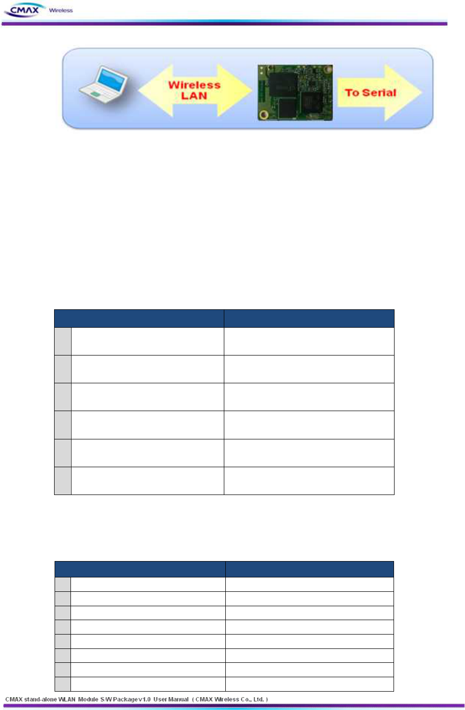
[Figure 5.2.3.1] Wireless LAN to Serial
6. Configuration Tool Command List
It should be explained the command for CMAX module and PC through Serial interface and
WLAN.
6.1 Configuration Tool Protocol
6.1.1 Serial Operation Specification
OPERATION
SPECIFICATION
1
Configuration Data Get
Baud Rate : 230,400
Hardware Handshaking : CTS/RTS
2
Configuration Data Set
Baud Rate : 230,400
Hardware Handshaking : CTS/RTS
3
Firmware Upload
Baud Rate : 230,400
Hardware Handshaking : CTS/RTS
4
Certificate Upload
Baud Rate : 230,400
Hardware Handshaking : CTS/RTS
5
BSS Info Request
Baud Rate : 230,400
Hardware Handshaking : CTS/RTS
6
BSS Info Response
Baud Rate : 230,400
Hardware Handshaking : CTS/RTS
[Table 6.1.1.1] Serial Operation Specification
6.1.2 WLAN Operation Protocol & Port
OPERATION
PROTOCOL & PORT
1
Configuration Data Get
TCP , 3318
2
Configuration Data Set
TCP , 3318
3
Firmware Upload
TCP , 3318
4
Certificate Upload
TCP , 3318
5
BSS Info Request
TCP , 3318
6
BSS Info Response
TCP , 3318
7
Printer Search Request
UDP , 3337
8
Printer Search Response
UDP , 9000
50
www.cmaxwireless.co.kr
[Table 6.1.2.1] WLAN Operation Protocol & Port
6.2 Serial & WLAN Command
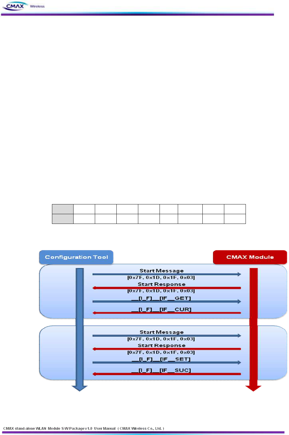
6.2.1 Serial Operation
l Serial mode Configuration Tool work should need ‘Start Message’ before sending real
command.
l Serial mode Configuration Tool command should change all ‘byte’ to ASCII code. And next
transmit.
n Ex : Command Frame
n If it changes hexadecimal code to ‘__[I_F]__[IF__GET]’. It is ‘0x5F, 0x5F, 0x49, 0x49, 0x5F,
0x46, 0x47, 0x5F, 0x5F, 0x5B, 0x49, 0x46, 0x5F, 0x5F, 0x5D, 0x45, 0x54, 0x47’.
n It should be transmitted ASCII value that the above hexadecimal value changed
n ‘0x5F’ is separated ASCII ‘5’(==0x35) and ASCII’F’(==0x46). and then WLAN module send
them by serial interface.
ASCII
_
[
I
F
]
G
E
T
HEX
0x5F
0x5B
0x49
0x46
0x47
0x5D
0x45
0x54
[Table 6.2.1.1] Serial Command ASCII, HEX
l Serial Command Sequence
[Figure 6.2.1.1] Serial Command Sequence
51
www.cmaxwireless.co.kr
l Serial Start Message Format
SERIAL START MESSAGE
VALUE
DIRECTION
COMMENT
Configuration Start Message
[0x7f, 0x1D, 0x1F, 0x03]
Host → Device
Configuration Start Response
[0x7f]
Device → Host
Firmware Update Start Message
[0x80, 0x1D, 0x1F, 0x03]
Host → Device
Firmware Update Start Response
['S', 'T', 'R', 'T']
Device → Host
CA_CER Update Start Message
[0x81, 0x1D, 0x1F, 0x03]
Host → Device
CA_CER Update Start Response
['S', 'T', 'R', 'T']
Device → Host
CL_KEY Update Start Message
[0x82, 0x1D, 0x1F, 0x03]
Host → Device
CL_KEY Update Start Response
['S', 'T', 'R', 'T']
Device → Host
CL_PEM Update Start Message
[0x83, 0x1D, 0x1F, 0x03]
Host → Device
CL_PEM Update Start Response
['S', 'T', 'R', 'T']
Device → Host
RSSI Request Message
[0x85, 0x1D, 0x1F, 0x03]
Device → Mobile Printer
RSSI response Message
[0x1D, 0x49, 0x02]
+ RSSI[2Byte]
Mobile Printer → Device
RSSI value is a
negative number
ETC
- if end of data is '0x03', 'Printer Server' send bypass at serial port(no
data operation).
- if ‘printer socket’’s state is ‘close’, received data is dumped.
[Table 6.2.1.2] Serial Start Message Format
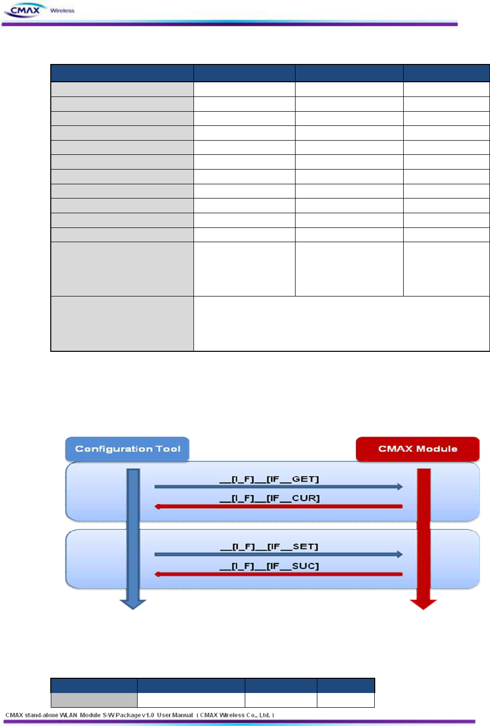
6.2.2 Wireless LAN Operation
l Wireless LAN Command Sequence
[Figure 6.2.2.1] Wireless LAN Command Sequence
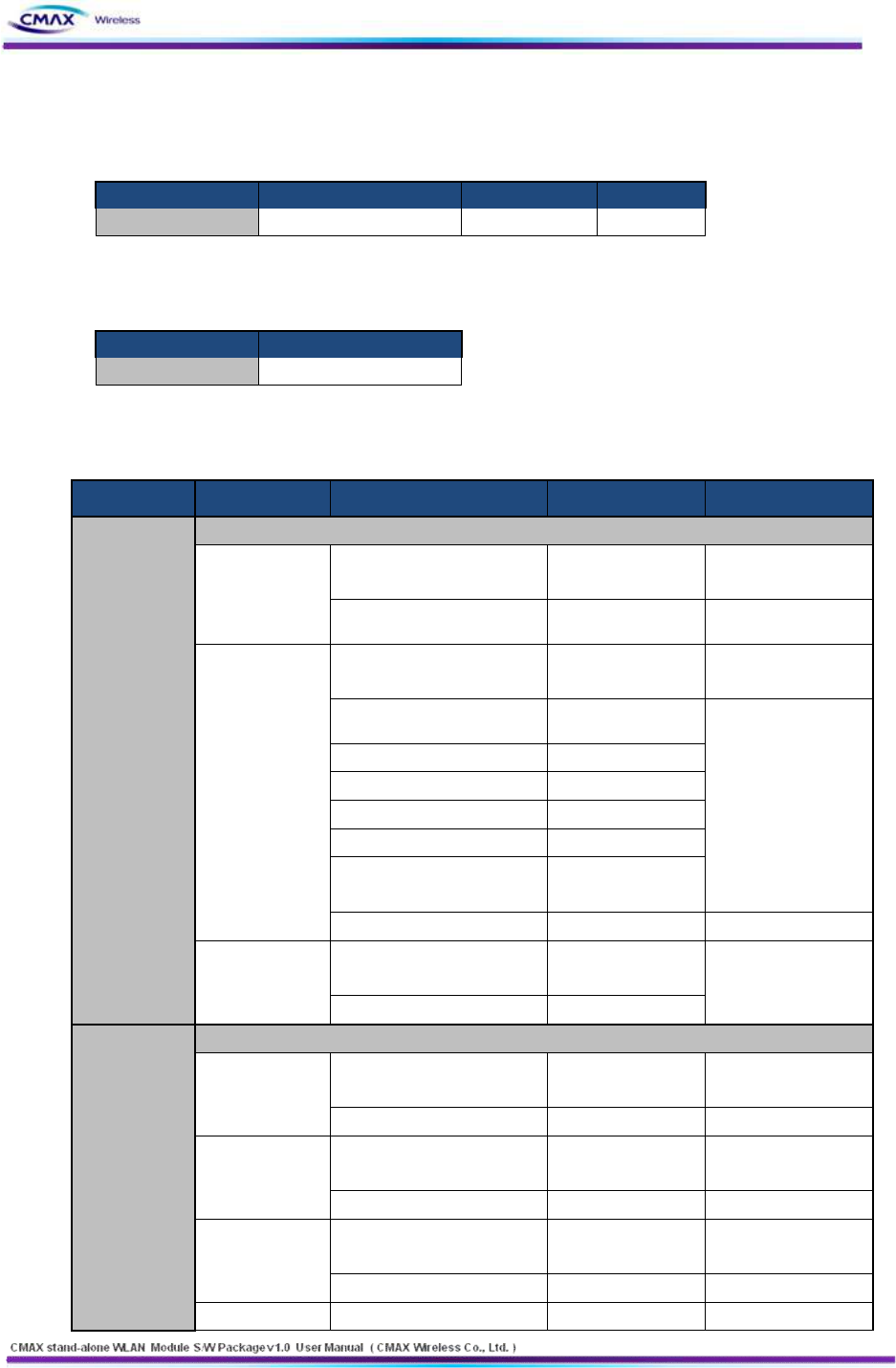
6.2.3 Serial & Wireless LAN Command Format
l Request Frame Format
DESCRIPTOR
STX (COMMAND CODE)
PARAMETER
ETX
Length(bytes)
18
Variable
2
52
www.cmaxwireless.co.kr
[Table 6.2.3.1] Request Frame Format (Serial & WLAN)
l Response Frame Format
DESCRIPTOR
STX (COMMAND CODE)
PARAMETER
ETX
Length(bytes)
18
Variable
2
[Table 6.2.3.2] Response Frame Format (Serial & WLAN)
l ETX Frame Format
SETTING
FORMAT
ETX
ETXETX = 0x030x03
[Table 6.2.3.3] ETX Frame Format (Serial & WLAN)
l STX (Command Code) Frame Format
FUNCTION
OPERATION
MESSAGE VALUE
SIZE
COMMENT
PRINTER
SEARCH
WLAN MODE ONLY
Search Request
(Host→Device)
Search Request
CMD("__[I_F]__[PRT_REG]")
unsigned char[18]
Check sum
unsigned char[2]
Search
Response
(Device→Host)
Search Response
CMD("__[I_F]__[PRT_RSP]")
unsigned char[18]
PrinterType
unsigned char[32]
Maximum Message
Size : 9KByte below
Device
information(Printer
Type to Printer Port)
is able to added
repeatedly (MAX
Device : 100)
SystemName
unsigned char[32]
SystemVersion
unsigned char[9]
IP Address
unsigned char[4]
MAC Address
unsigned char[6]
Printer Port
unsigned char[2]
Check sum
unsigned char[2]
Message FAIL
(Host↔Device)
FAIL
CMD("__[I_F]__[___FAIL]")
unsigned char[18]
Fail response
Check sum
unsigned char[2]
GET
CONFIGURATI
ON
SERIAL & WLAN
Connect
Request
(Host→Device)
System Request
CMD("__[I_F]__[SYS_REQ]")
unsigned char[18]
Check sum
unsigned char[2]
Connect
Request
(Device→Host)
Search Request
CMD("__[I_F]__[SYS_RSP]")
unsigned char[18]
Check sum
unsigned char[2]
Configuration
Get Value
(Host→Device)
Configuration Get Value
CMD("__[I_F]__[IF__GET]")
unsigned char[18]
Check sum
unsigned char[2]
Configuration
Configuration Current Value
unsigned char[18]
53
www.cmaxwireless.co.kr
Current Value
(Device→Host)
CMD("__[I_F]__[IF__CUR]")
SystemName
unsigned char[32]
Region
unsigned char
Region
information(RF)
NetworkMode
unsigned char
Infra/Adhoc/P2P
IpConfigMode
unsigned char
Static/DHCP
IP Address
unsigned char[4]
SubNetMask
unsigned char[4]
Gateway
unsigned char[4]
SSID
unsigned char[32]
AUTH Mode
unsigned char
Open, Shared,
WPA1PSK, WPA2PSK,
WPA1EAP, WPA2EAP
Crypto Mode
unsigned char
WEP64/128, TKIP,
AES
WEP Key_0
unsigned char[26]
It use one only.
WEP Key_1
unsigned char[26]
WEP Key_2
unsigned char[26]
WEP Key_3
unsigned char[26]
PSK Key
unsigned char[64]
Adhoc channel
unsigned char
EAP Mode
unsigned char
TLS, TTLS, PEAP,
LEAP
EAP ID
unsigned char[32]
EAP PASSWORD
unsigned char[32]
USER NAME
unsigned char[32]
System ID
USER PASSWORD
unsigned char[32]
System Password
PRINTER Port
unsigned char[2]
Dummy
unsigned char
Channel Search
SysContact
unsigned char[64]
SysLocation
unsigned char[64]
ipDefaultTTL
unsigned char
Dummy
unsigned char
Power save
isWebSSL
unsigned char
isTelnet
unsigned char
isFTP
unsigned char
isSNMP
unsigned char
isSNMPTrap
unsigned char
SNMPSetCommunity
unsigned char[16]
SNMPGetCommunity
unsigned char[16]
SNMPTrapCommunity
unsigned char[16]
TrapIP
unsigned char[4]
IncativityTime
unsigned char[2]
Check sum
unsigned char[2]
54
www.cmaxwireless.co.kr
Message FAIL
(Host↔Device)
FAIL
CMD("__[I_F]__[___FAIL]")
unsigned char[18]
Fail response
Check sum
unsigned char[2]
SET
CONFIGURATI
ON
SERIAL & WLAN
Connect
Request
(Host→Device)
System Request
CMD("__[I_F]__[SYS_REQ]")
unsigned char[18]
Check sum
unsigned char[2]
Connect
Request
(Device→Host)
Search Request
CMD("__[I_F]__[SYS_RSP]")
unsigned char[18]
Check sum
unsigned char[2]
Configuration
Set Value
(Host→Device)
Configuration Set Value
CMD("__[I_F]__[IF__SET]")
unsigned char[18]
SystemName
unsigned char[32]
Region
unsigned char
Region
information(RF)
NetworkMode
unsigned char
Infra/Adhoc/P2P
IpConfigMode
unsigned char
Static/DHCP
IP Address
unsigned char[4]
SubNetMask
unsigned char[4]
Gateway
unsigned char[4]
SSID
unsigned char[32]
AUTH Mode
unsigned char
Open, Shared,
WPA1PSK, WPA2PSK,
WPA1EAP, WPA2EAP
Crypto Mode
unsigned char
WEP64/128, TKIP,
AES
WEP Key_0
unsigned char[26]
It use one only.
WEP Key_1
unsigned char[26]
WEP Key_2
unsigned char[26]
WEP Key_3
unsigned char[26]
PSK Key
unsigned char[64]
Adhocchannel
unsigned char
EAP Mode
unsigned char
TLS, TTLS, PEAP,
LEAP
EAP ID
unsigned char[32]
EAP PASSWORD
unsigned char[32]
USER NAME
unsigned char[32]
System ID
USER PASSWORD
unsigned char[32]
System Password
PRINTER Port
unsigned char[2]
Dummy
unsigned char
Channel Search
SysContact
unsigned char[64]
SysLocation
unsigned char[64]
ipDefaultTTL
unsigned char
Dummy
unsigned char
Power save
55
www.cmaxwireless.co.kr
isWebSSL
unsigned char
isTelnet
unsigned char
isFTP
unsigned char
isSNMP
unsigned char
isSNMPTrap
unsigned char
SNMPSetCommunity
unsigned char[16]
SNMPGetCommunity
unsigned char[16]
SNMPTrapCommunity
unsigned char[16]
TrapIP
unsigned char[4]
IncativityTime
unsigned char[2]
Check sum
unsigned char[2]
Message
SUCCESS
(Device→Host)
SUCCESS
CMD("__[I_F]__[IF__SUC]")
unsigned char[18]
Check sum
unsigned char[2]
Message FAIL
(Host↔Device)
FAIL
CMD("__[I_F]__[___FAIL]")
unsigned char[18]
Fail response
Check sum
unsigned char[2]
BSS
INFORMATIO
N
SERIAL & WLAN
BSS Information
Request
(Host→Device)
BSS Info Request
CMD("__[I_F]__[BSS_REQ]")
unsigned char[18]
Check sum
unsigned char[2]
BSS Information
Response
(Device→Host)
BSS Info Response
CMD("__[I_F]__[BSS_RSP]")
unsigned char[18]
SSID Type
unsigned char
Maximum Message
Size : 5KByteb
below(WLAN)
10Kbyte
below(Serial) AP
information(‘SSID’ to
‘Security’) is able to
added repeatedly
(MAX Device : 100)
SSID Length
unsigned char
SSID Value
variable
(MAX 32)
BSSID Type
unsigned char
BSSID length
unsigned char
BSSID Value
unsigned char[6]
NetworkMode
unsigned char
RSSI
unsigned char[2]
Security
unsigned char
WEP64 0, WEP128 1,
WPA1 2, WPA2 3
Check sum
unsigned char[2]
Message FAIL
(Host↔Device)
FAIL
CMD("__[I_F]__[___FAIL]")
unsigned char[18]
Fail response
Check sum
unsigned char[2]
FIRMWARE
UPLOAD
SERIAL & WLAN
FW Data
Message
(Host→Device)
FW Data
CMD( "__[I_F]__[FW_DATA]")
unsigned char[18]
FW Data Length
unsigned char[8]
FW Data
variable
MAX Size :
56
www.cmaxwireless.co.kr
20Kbyte(WLAN),
15Kbyte(Serial)
Check sum
unsigned char[2]
Message
SUCCESS
(Device→Host)
SUCCESS
CMD("__[I_F]__[IF__SUC]")
unsigned char[18]
Receive Success
response
Check sum
unsigned char[2]
FW END
Message
(Host→Device)
FW END
CMD("__[I_F]__[FW__END]")
unsigned char[18]
End of Firmware
transmit
Check sum
unsigned char[2]
Message
SUCCESS
(Device→Host)
SUCCESS
CMD("__[I_F]__[IF__SUC]")
unsigned char[18]
Success response
Check sum
unsigned char[2]
Message FAIL
(Host↔Device)
FAIL
CMD("__[I_F]__[___FAIL]")
unsigned char[18]
Fail response
Check sum
unsigned char[2]
FW CANCEL
Request
(Host→Device)
FW CRC
ERROR("__[I_F]__[FW_XREQ]"
)
unsigned char[18]
Check sum
unsigned char[2]
FW CANCEL
Response
(Device→Host)
FW CRC
ERROR("__[I_F]__[FW_XRSP]")
unsigned char[18]
Check sum
unsigned char[2]
FW CRC ERR
Message
(Host↔Device)
FW CRC
ERROR("__[I_F]__[CRC_ERR]")
unsigned char[18]
Verify does ‘FW
Data’ after Flash
write one.
Check sum
unsigned char[2]
CERTIFICATE
(CA, CLIENT
KEY, CLIENT
PEM,
FAST PAC)
UPLOAD
SERIAL MODE ONLY
Certificate Data
Message
(Host→Device)
Certificate Data
CMD("__[I_F]__[FW_CERT]")
unsigned char[18]
In serial Mode
‘Certificate Data
Message’ is
performed only by
using the ‘Certificate
Upload’.
(Certificate is
classified by using
the ‘ Serial Start
command)
Max Size : 500byte
Certificate Size
unsigned char[8]
Certificate Data
variable
Check sum
unsigned char[2]
Certificate Data
End Message
(Device→Host)
Certificate Data END
CMD("__[I_F]__[CERTEND]")
unsigned char[18]
Certificate Size
unsigned char[8]
Certificate Data
variable
Max Size : 500byte
Check sum
unsigned char[2]
Message
SUCCESS
unsigned char[18]
Success response
57
www.cmaxwireless.co.kr
SUCCESS
(Device→Host)
CMD("__[I_F]__[IF__SUC]")
Check sum
unsigned char[2]
CA
UPLOAD
WLAN MODE ONLY
CA Data
Message
(Host→Device)
CA Data
CMD("__[I_F]__[CA_CERT]")
unsigned char[18]
CA Data Size
unsigned char[8]
CA Data
variable
Max Size : 500byte
Check sum
unsigned char[2]
Certificate Data
End Message
(Device→Host)
Certificate Data END
CMD("__[I_F]__[CERTEND]")
unsigned char[18]
Certificate Size
unsigned char[8]
Certificate Data
variable
Max Size : 500byte
Check sum
unsigned char[2]
Message
SUCCESS
(Device→Host)
SUCCESS
CMD("__[I_F]__[IF__SUC]")
unsigned char[18]
Success response
Check sum
unsigned char[2]
CLIENT KEY
UPLOAD
WLAN MODE ONLY
Client Key Data
Message
(Host→Device)
Client Key Data
CMD("__[I_F]__[CK_CERT]")
unsigned char[18]
Client Key Data Size
unsigned char[8]
Client Key Data
variable
Max Size : 500byte
Check sum
unsigned char[2]
Certificate Data
End Message
(Device→Host)
Certificate Data END
CMD("__[I_F]__[CERTEND]")
unsigned char[18]
Certificate Size
unsigned char[8]
Certificate Data
variable
Max Size : 500byte
Check sum
unsigned char[2]
Message
SUCCESS
(Device→Host)
SUCCESS
CMD("__[I_F]__[IF__SUC]")
unsigned char[18]
Success response
Check sum
unsigned char[2]
CLIENT PEM
UPLOAD
WLAN MODE ONLY
Client PEM Data
Message
(Host→Device)
Client PEM Data
CMD("__[I_F]__[CP_CERT]")
unsigned char[18]
Client PEM Data Size
unsigned char[8]
Client PEM Data
variable
Max Size : 500byte
Check sum
unsigned char[2]
Certificate Data
End Message
(Device→Host)
Certificate Data END
CMD("__[I_F]__[CERTEND]")
unsigned char[18]
Certificate Size
unsigned char[8]
Certificate Data
variable
Max Size : 500byte
Check sum
unsigned char[2]
Message
SUCCESS
(Device→Host)
SUCCESS
CMD("__[I_F]__[IF__SUC]")
unsigned char[18]
Success response
Check sum
unsigned char[2]

58
www.cmaxwireless.co.kr
[Table 6.2.3.4] STX Command Frame Format (Serial & WLAN)
7. Technical Support, Warranty, and Precaution
7.1 Technical Support
If you have any question regarding operation of the product, visit the message board on
CMAX Wireless’s web site or send us an email at the following address:
l E-mail: ursus@cmaxwireless.com
l For more information, visit our website at http://www.cmaxwireless.co.kr
7.2 Warranty
7.2.1 Refund
Upon the customer’s request to refund the product within two weeks after purchase,
CMAX Wireless will refund the product.
7.2.2 Free Repair Services
For product failures occurring within one year after purchase, CMAX Wireless provides
free repair services or exchange the product. However, if the product failure is due to
user’s fault, repair service fees will be charged or the product will be replaced at user’s
expense.
7.2.3 Charged Repair Services
For product failures occurring after the warranty period (one year) or resulting from
user’s fault, repair service fees will be charged and the product will be replaced at user’s
expense.
7.3 Precaution
l CMAX Wireless is not responsible for product failures occurring due to user’s alternation
of the product.
l Specifications of the product are subject to change without prior notice for performance
improvement.

59
www.cmaxwireless.co.kr
l CMAX Wireless does not guarantee successful operation of the product if the product
was used under conditions deviating from the product specifications.
l Reverse engineering of firmware and applications provided by CMAX Wireless is
prohibited.
l Use of firmware and applications provided by CMAX Wireless for purposes other than
those for which they were designed is prohibited.
l Do not use the product in an extremely cold or hot place or in a place where vibration is
severe.
l Do not use the product in an environment in which humidity is high or a lot of oil exists.
l Do not use the product where there is caustic or combustible gas.
l CMAX Wireless does not guarantee normal operation of the product under the
conditions a lot of noise exists.
l Do not use the product for a purpose that requires exceptional quality and reliability
relating to user’s injuries or accidents - aerospace, aviation, health care, nuclear power,
transportation, and safety purposes.
l CMAX Wireless is not responsible for any accident or damage occurring while using the
product.
l This device complies with part 15 of the FCC Rules. Operation is subject to the following
two conditions: (1) This device may not cause harmful interference, and (2) this device
must accept any interference received, including interference that may cause undesired
operation.
l Any changes or modifications not expressly approved by the party responsible for
compliance could void the user’s authority to operate the equipment.

60
www.cmaxwireless.co.kr
7.4 Labeling
l FCC ID: U5MWD-MSB
The proposed with FCC ID label format is to be placed on the module. If FCC ID is not
visible when the module is installed into the system, “Contains FCC ID:U5MWD-MSB ”
shall be placed on the outside of final host system.
l Caution: Exposure to Radio Frequency Radiation.
To comply with FCC RF exposure compliance requirements, a separation distance of at
least 20 cm must be maintained between the antenna of this device and all persons.
*The module is limited to OEM installation only.
OEM integrators must ensure that the end-user has no manual instructions to remove or install the
module. OEM's must comply with FCC marking regulation part 15 declaration of conformity
(Section 2.925(e)).
This module is to be installed only in mobile or fixed applications (Please refer to FCC CFR 47 Part
2.1091(b) for a definition of mobile and fixed devices).
The separate approval is required for all operating configurations, including portable configurations
with respect to FCC CFR 47 Part 2.1093 and different antenna configurations.
The WD-MSB Module has been designed to operate with the following antenna and gains. Use with
other antenna types or with these antenna types at higher gains is strictly prohibited.
Manufacturer
Type of
Antenna
Model
Gain (dB)
Type of Connector
Nice Korea
Components Co.,
Ltd
Chip Antenna
NKCBTF-F02
3.91
Permanent
integral
COPYRIGHT NOTICE
Copyright ⓒ CMAX Wireless co., Ltd. All rights Reserved.
For more information, visit our website at http://www.cmaxwireless.co.kr