BMI Technologies RFVI-II VUI-II User Manual Instalation Instructions
BMI Technologies Inc. VUI-II Instalation Instructions
Contents
- 1. Draft Manual
- 2. Instalation Instructions
Instalation Instructions

BMI TECHNOLOGIES INC.
Bay 3 7317 12 Street SW, Calgary, Alberta CANADA T2H 2S6
Toll-free: 1 800 563-8867 Tel: (403) 244-3901 Fax: (403) 229-0135
VEHICLE MONITOR
INSTALLATION INSTRUCTIONS

G FORCE PLUS RF Vehicle Monitor Installation Instructions
1 June/07
BMI Warranty Policy
BMI Technologies Inc. (BMI) warrants to the original customer that its products are of the highest
standards and every effort has been made to deliver a product that is free of defect. Should the
product fail within one (1) year from date of sale, BMI will, at its discretion, repair or replace the
defective product at no charge.
If your product does not perform as promised, contact BMI Technical Assistance (1-800-563-8867) for an
assessment of the problem. To aid in troubleshooting, be prepared to provide product Serial Number(s).
Before your product can be returned, you will require a Return Goods Authorization number (RGA#). Product
must be shipped at your cost via traceable means within 30 days of the issue date of the RGA. Any charges
associated with shipping due to incorrect paperwork will be charged back to you. Please contact BMI for any
needed assistance. Returned product cannot be accepted at BMI unless the RGA# is clearly labeled on the
outside of the package.
Final warranty determination is at the discretion of BMI on receipt and inspection of the returned product.
No warranty applies where there is evidence of misuse, improper installation, unauthorized modifications or
repairs, vandalism, fire, or contact with corrosive materials. Defacing hardware in any way, will limit
warranty options to repair and return only. Defaced units will not be replaced or credited
If product returned under warranty is deemed to work properly, the customer will be responsible for a $50.00
No Fault Found fee as well as freight charges to return the product.
This warranty applies to product only and does not include labor or any other charges.
BMI Return Policy
To return unused product in its original packaging, contact BMI Order Desk (1-800-563-8867) for a Return
Goods Authorization number (RGA#). Returns are accepted within 90 days of the original invoice date.
Returns must be shipped at your cost via traceable means within 30 days of the issue date of the RGA.
Returns cannot be accepted at BMI unless the RGA# is clearly labeled on the outside of the package.
Credits issued for returned product are subject to a 25% handling fee and are at the discretion of BMI
Technologies Inc. after inspection of the returned goods. No returns on keys or cards.
Credits will be issued within 6-8 weeks. Please note BMI does not issue checks, credits will be applied toward
the customer’s account.
Non-Warranty Repairs
To ship items for non-warranty repair, contact BMI Order Desk (1-800-563-8867) for a Return Goods
Authorization number (RGA#) and to provide a Purchase Order number for the work to be done.
Items must be shipped at your cost and cannot be accepted at BMI unless the RGA# is clearly labeled on the
outside of the package.

G FORCE PLUS RF Vehicle Monitor Installation Instructions
June/07 2
FCC AND IC REGULATORY DECLARATIONS
Federal Communications Commission (FCC) and Industry Canada (IC) regulations require the inclusion of this
section in the Instruction Manual.
SPECIAL ACCESSORIES
The provided antenna, which operates in the 902 to 928 MHz frequency band, and antenna extension cable,
must be used with the G FORCE PLUS RF Host Transceiver, G FORCE PLUS RF Zone Transceiver and G
FORCE PLUS RF Vehicle Monitor. No substitutions are allowed.
INTERFERENCE
The G FORCE PLUS RF Vehicle Monitor antenna and the G FORCE PLUS Vehicle Interface may not be
located closer than 20cm to each other.
These devices comply with Part 15 of the FCC Rules. Operation is subject to the following two conditions:
(1) the devices may not cause harmful interference, and (2) the devices must accept any interference received,
including interference that may cause undesired operation.
COMPONENT CHANGES OR MODIFICATIONS
Changes or modifications not expressly approved by the party responsible for compliance could void the
user’s authority to operate the G FORCE PLUS Vehicle Interface, G FORCE PLUS Data Logger, G FORCE
PLUS RF Vehicle Monitor, G FORCE PLUS RF Host Transceiver, and G FORCE PLUS RF Zone
Transceiver.
RF EXPOSURE WARNING
The following warning applies to the G FORCE PLUS Vehicle Interface, G FORCE PLUS RF Vehicle
Monitor, G FORCE PLUS RF Host Transceiver, and G FORCE PLUS RF Zone Transceiver:
WARNING: This device exceeds the FCC/IC requirements for RF exposure when the antenna used for this
transmitter has a separation distance of at least 20 cm from all persons and must not be co-located or
operating in conjunction with any other antenna or transmitter which is closer than 20 cm.
The installer of this radio equipment must ensure that the antenna is located or pointed such that it does not
emit RF field in excess of Health Canada limits for the general population as indicated by Safety Code 6.
G FORCE PLUS RF Vehicle Monitor Installation Instructions
3 June/07
INSTALLATION INSTRUCTIONS
This section provides the installation instructions for the G FORCE PLUS RF system.
VEHICLE MONITOR AND INTERFACE
The Vehicle Monitor and Vehicle Interface installation instructions follow. A copy is also included with each
Vehicle Monitor shipped.
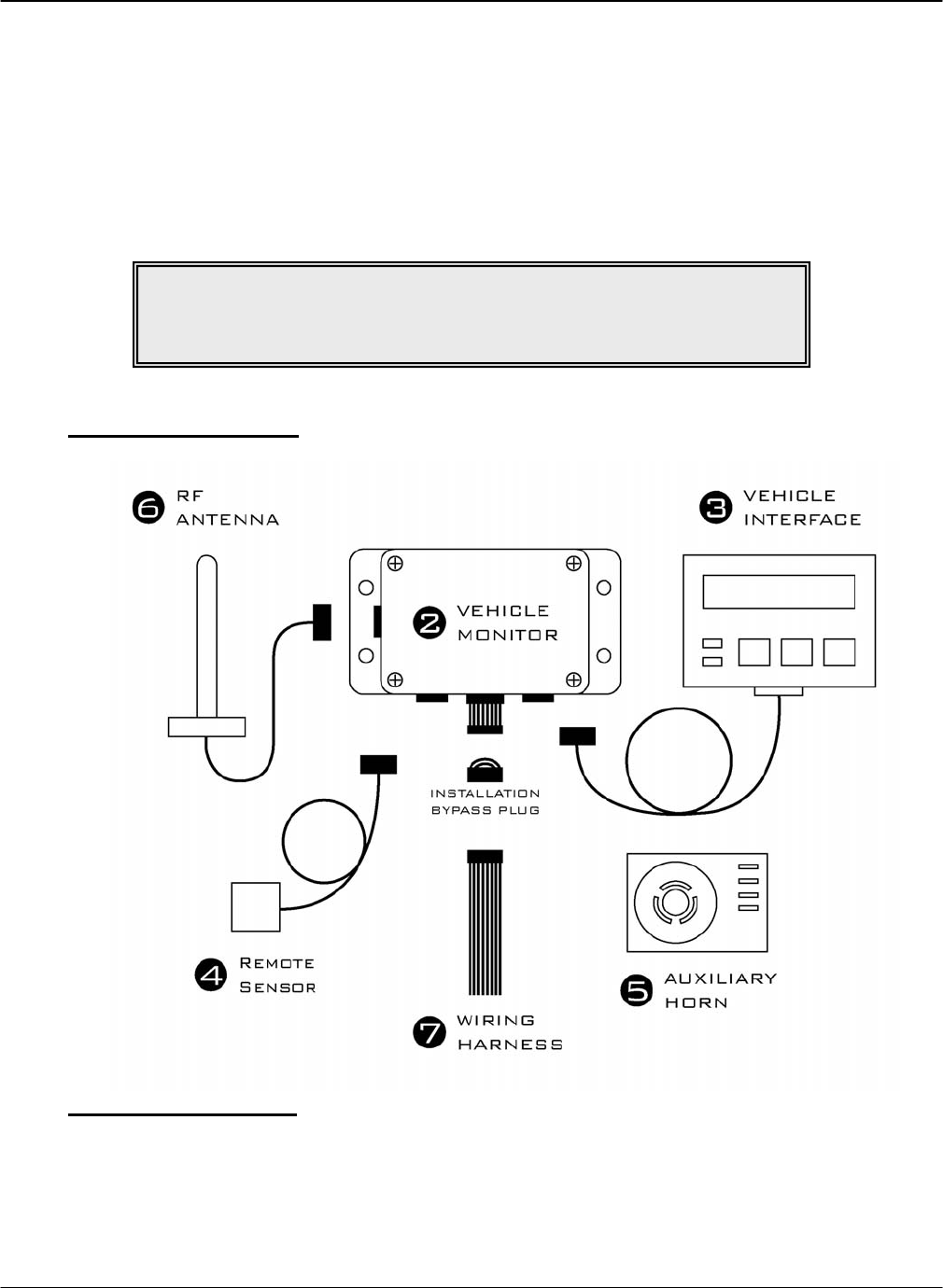
Component Overview
Electrical Description
Input Fuse (F1) 12 – 60 volts 1A DC Slow
Lift Interrupt Relay Fuse (F2) Max 60 volts 3.5A DC Slow
Secondary Alarm Relay Fuse (F4) Max 60 volts 3A DC Slow
Horn Relay Fuse (F3) Max 60 volts 3A DC Slow
NOTE!
Vehicle Monitor and Vehicle Interface installation may be done
at the same time as the Software and Software Interface installation.

G FORCE PLUS RF Vehicle Monitor Installation Instructions
June/07 4
Installation Steps
NOTE!
Wires and cables should be installed to avoid chafing and excess slack.
Cable ties, clamps, grommets, looms, sleeves, supplementary insulation,
conduit, and routing are acceptable provisions.
Wires and cables mounted on a boom, lift, or other similar moving part
should be installed so that they are not subject to damage or failure as a
result of kinking or abrasion.
Wires and cables should be installed to maintain clearance from moving
parts, hot engine parts, exhaust systems, fuel systems and surfaces that are
subject to accumulation of oil, grease, or dirt.
NOTE!
The G FORCE PLUS RF Vehicle Monitor antenna and
the G FORCE PLUS Vehicle Interface
may not be located closer than 20cm to each other.
WARNING!
This device exceeds the FCC/IC requirements for RF exposure when the
antenna used for this transmitter has a separation distance of at least 20 cm
from all persons and must not be co-located or operating in conjunction with
any other antenna or transmitter which is closer than 20 cm.
The installer of this radio equipment must ensure that the antenna is located
or pointed such that it does not emit RF field in excess of Health Canada
limits for the general population as indicated by Safety Code 6.
WARNING!
The brass nut that connects the antenna to the antenna cable MUST be
electrically insulated from the frame of the vehicle.

G FORCE PLUS RF Vehicle Monitor Installation Instructions
5 June/07
Follow the steps in the order below and refer to the diagram in the “Component Overview”.
1. Disconnect the vehicle battery
Check the power circuit with a multi-meter or other testing device to ensure the absence of any
residual voltage.
2. Mount the Vehicle Monitor onto the vehicle.
The optimal location for the Vehicle Monitor is within the plan form of the vehicle where it will
be safe from electrical controls, engine heat, possible impacts, and vandalism.
Use the base of the Vehicle Monitor as a template to drill four ¼-inch holes in the selected
location and attach the Vehicle Monitor using the hardware provided.
3. Mount and connect the Vehicle Interface.
The Vehicle Monitor antenna and the Vehicle Interface may not be located closer than 20cm to
each other.
Secure the Vehicle Interface to an ergonomically accessible location on the Vehicle.
Feed the Vehicle Interface cable to the Vehicle Monitor and plug the cable end’s 4-pin male
connector into the 4-pin female receptacle on the Vehicle Monitor. Secure the connector.
4. Mount and connect the Remote Sensor.
The optimal location for the Remote Sensor is on a rigid part of the vehicle 2 to 4 feet from the
floor (i.e. the frame). Overhead racks or masts are unsuitable.
Some recommended mounting locations are:
Sit-downs: Under the floor plate on the left or right side frame with a minimum
distance of 12 inches from the battery compartment on battery-powered
vehicles
Stand-ups: 1-2 inches below the front cover/dash on the left or right inside perimeter
of the frame
Turret trucks: As high as possible on the main frame and as close as possible to the mast.
Walkies: As low as possible under the cowl/cover on the main frame.
Walkie-riders: As low as possible under the cowl/cover on the main frame.
Use the metal bracket provided to mount the Remote Sensor as parallel to the floor as possible,
and so that the labelled arrows match the direction of the vehicle’s travel (the cable should exit
from the top or bottom of the Remote Sensor).
Or if preferred, clean the mounting surface thoroughly with degreaser and then mount the Remote
Sensor using the 3M™ Dual Lock™ provided.
Feed the Remote Sensor cable to the Vehicle Monitor and plug the cable end’s 6-pin male
connector into the 6-pin female receptacle on the Vehicle Monitor. Secure the connector.
Secure the cable to the vehicle within 3 inches of the Remote Sensor.
5. Mount the Auxiliary Horn.
The optimal location for the Auxiliary Horn is where it will be audible and safe from electrical
controls, engine heat and vandalism.
Clean the mounting surface thoroughly with degreaser and then mount the Horn using the 3M™
Dual Lock™ provided.
6. Mount and connect the antenna.
The optimal location for the antenna is:
On a rigid part of the vehicle, safe from electrical controls, engine heat, moving parts and
vandalism,
As high as possible from the floor,

G FORCE PLUS RF Vehicle Monitor Installation Instructions
June/07 6
At least two feet away from any large metal mass for best communications results.
Attach the metal bracket provided to the selected location so the antenna will be vertical.
Insert the antenna into the bracket slot and secure the antenna by tightening the nut.
Prevent movement/vibration of the metal connector located between the short black and long
copper-colored cables by securing the cables and protecting the connector if necessary.
7. Wire the Vehicle Monitor.
Remove the Installation Bypass Plug from the end of the Wiring Harness and connect the Wiring
Harness to the Vehicle Monitor.
Connect the wires to the vehicle as follows:
Orange wire: Connect this wire to unswitched battery positive on a 12-
volt IC truck. Tie this wire back if it is not used.
Red wire/battery positive: Connect this wire to unswitched battery positive on a 24-
volt battery. Tie this wire back if it is not used, or if this
is an internal-combustion vehicle installation.
Red and white wire/battery positive: Connect this wire to unswitched battery positive on a 36-
or 48-volt battery. Tie this wire back if it is not used, or
if this is an internal-combustion vehicle installation.
Black wire/battery negative: For battery-powered vehicles, connect this wire directly
to battery negative as close to the battery terminal as
possible. For internal-combustion vehicles, connect this
wire to the frame or any vehicle ground.
Green wires/key-on detect: Connect one green wire to switched battery plus.
IMPORTANT! On an IC truck, this green wire MUST
be connected to the IGNITION contact of the keyswitch,
not the ACCESSORY contact. If it is connected to the
accessory contact, the connection will be broken when
the starter is engaged, which will turn the GForce unit
off.
Connect the second green wire directly to battery minus
as close to the battery terminal as possible. For internal-
combustion vehicles, connect the second green wire to
the frame or any vehicle ground.
NOTE!
Keep the Installation Bypass Plug in a safe place.
You will need it again for step 9.
NOTE!
The provided antenna, which operates in the 902 to 928 MHz frequency
band, and antenna extension cable,
must be used with the G FORCE PLUS RF Vehicle Monitor.
No substitutions are allowed.
G FORCE PLUS RF Vehicle Monitor Installation Instructions
7 June/07
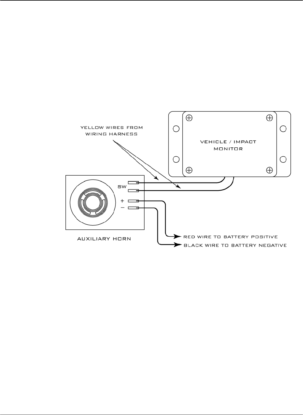
Yellow wires/Auxiliary Horn: Connect one yellow wire to one of the two Auxiliary
Horn terminals labelled “SW”. Connect the second
yellow wire to the second Auxiliary Horn “SW”
terminal. Use a suitable length of red wire to make a
connection between the positive terminal on the
Auxiliary Horn (labelled “+”) and battery positive. An
unused portion of red battery positive wire from the
Wiring Harness may be used. Similarly, use a suitable
length of black wire to make a connection between the
negative terminal on the Auxiliary Horn (labelled “–”)
and battery negative. An unused portion of black battery
negative wire from the Wiring Harness may be used.
White wires/digital sense input: These wires are used to detect vehicle motion or lift
operation. For customized help with your particular
installation, contact Technical Assistance at BMI
Technologies Inc. at 1-800-563-8867.
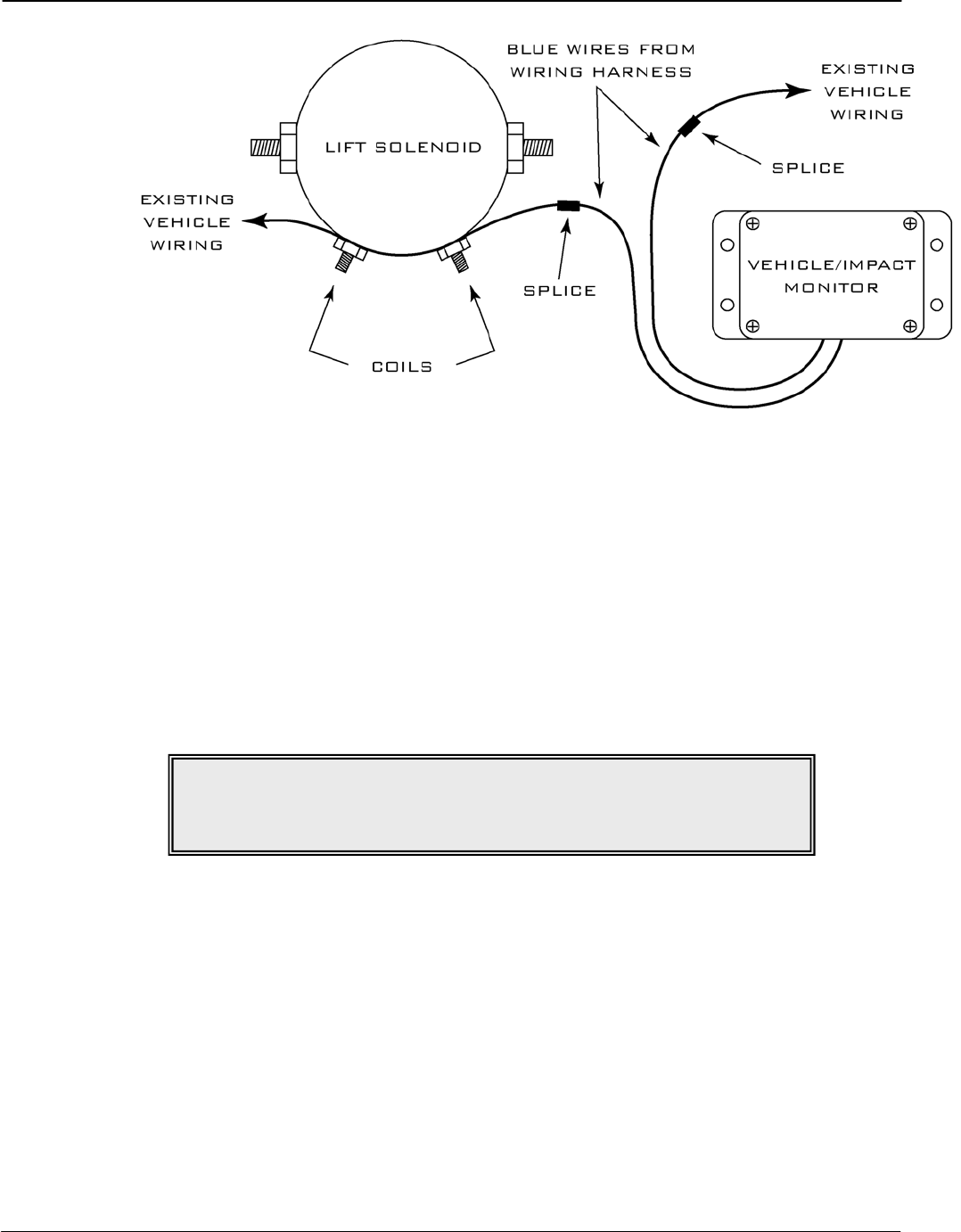
Blue wires/lift interrupt: Use these wires to interrupt the lift solenoid on battery-
powered vehicles if desired. The contact on the blue
wires is fused at 3 amps – do not create a circuit that
exceeds this rating. Remove one vehicle wire at the coil
of the lift solenoid. Splice one blue wire to the wire just
removed. Connect the other blue wire to the vehicle lift
solenoid terminal. Tie these wires back if they are not
used, or if this is an internal-combustion vehicle
installation.
G FORCE PLUS RF Vehicle Monitor Installation Instructions
June/07 8
Purple wires/secondary alarm: Use these wires to create a secondary alarm if desired.
The contact on the purple wires is fused at 3 amps – do
not create a circuit that exceeds this rating. For
customized help with your particular installation, contact
Technical Assistance at BMI Technologies Inc. at 1-800-
563-8867. Tie these wires back if they are not used.
8. Reconnect the battery and turn on the vehicle ignition to test the installation.
The vehicle should power up and the Vehicle will be in Maintenance Lockout. The Vehicle
Interface will display “MAINT LOCK OUT DD/MM/YYYY HH:MM”.
If the blue wires were connected for lift interrupt, the lift will be disabled.
If the purple wires were connected for a secondary alarm, the vehicle’s behavior will reflect a
secondary alarm condition.
9. Complete or pause the installation.
Refer to the section in the Instruction Manual that explains how to program the Vehicle Monitor
settings, OR
Disconnect the Vehicle Monitor and Wiring Harness and reconnect the Installation Bypass Plug
to the end of the Wiring Harness to allow full vehicle use and to defer the programming of
Vehicle Monitor settings.
NOTE!
If the installation test fails, contact Technical Assistance
at BMI Technologies Inc. at 1-800-563-8867.