BMW X5 To The Manual Cf0713e4 011a 4259 8e91 Ca3e5152d378
User Manual: BMW X5 to the manual
Open the PDF directly: View PDF ![]() .
.
Page Count: 38
- EN / Xenon lights with automatic headlight adjustment control system
- Contents
- 1. Important information
- 2. Installation
- 2.1 Preparation
- 2.2 To install the level sensor at the front right
- 2.3 To install the level sensor at the rear right
- Fold out folded page 2-33.
- 2.4 Connection overview of the xenon wiring harness (ECE cars only)
- Fold out folded page 2-43
- 2.5 To install the xenon wiring harness (ECE cars only)
- Fold out folded page 2-77.
- 2.6 Connection overview of the xenon wiring harness (ECE cars only)
- Fold out folded page 2-95
- 2.7 To install the xenon wiring harness (US cars only)
- Fold out folded page 2-129
- 2.8 To remove the manual headlight adjustment control system (ECE cars only)
- 2.9 To install the xenon headlights
- 2.10 To affix the warning sticker
- 2.11 To assemble the car
- 2.12 Coding
- 2.13 Function test
- 2.14 To adjust the xenon headlights
- Fold out folded page 2-147.
- 3. Circuit diagram
Xenon-Licht mit automatischer Leuchtweitenregulierung
für BMW X5 (E53) LHD
Fachkenntnisse sind Voraussetzung.
BMW Parts and Accessories – Installation Instruction
Xenon lights with automatic headlight adjustment control system
for the BMW X5 (E53), LHD
Instructions de montage des pièces et des accessoires BMW
Eclairage au xénon avec réglage automatique de la portée des phares
pour BMW X5 (E53) à direction à gauche
BMW Onderdelen en accessoires – Montagehandleiding
Xenon-licht met automatisch instelling van de koplampen
voor BMW X5 (E53) LHD
BMW Delar och tillbehör – Monteringsanvisning
Xenonljus med automatisk ljusbreddsreglering
för BMW X5 (E53) vänsterstyrd
Ricambi e accessori BMW – Istruzioni di montaggio
Luci allo xeno con regolatore automatico della profondità d'illuminazione
per BMW X5 (E53) LHD
BMW piezas y accesorios – instrucciones de montaje
Luces de Xenón con regulación automática del alcance de las luces
para BMW X5 (E53) VVI
Peças e Acessórios BMW – Instruções de Montagem
Luz de xénon com regulação automática do alcance dos faróis
para os modelos BMW X5 (E53) de volante à esquerda
Best.-Nr. 01 29 0 007 010 XI/99 Printed in Germany
Teile und Zubehör - Einbauanleitung
F 53 0054 EVA

Inhalt Seite
1 Wichtige Hinweise . . . . . . . . . . . . . . . . . . . . . . . . . . . . . . . . . . 1-1
2 Einbau . . . . . . . . . . . . . . . . . . . . . . . . . . . . . . . . . . . . . . . . . . 2-1
3 Stromlaufplan . . . . . . . . . . . . . . . . . . . . . . . . . . . . . . . . . . . . . 3-1
Contents Page
1 Important notes . . . . . . . . . . . . . . . . . . . . . . . . . . . . . . . . . . . . 1-3
2 Installation . . . . . . . . . . . . . . . . . . . . . . . . . . . . . . . . . . . . . . . . 2-5
3 Circuit diagrams . . . . . . . . . . . . . . . . . . . . . . . . . . . . . . . . . . . 3-1
Sommaire Page
1 Recommandations importantes . . . . . . . . . . . . . . . . . . . . . . . . 1-5
2 Montage . . . . . . . . . . . . . . . . . . . . . . . . . . . . . . . . . . . . . . . . . 2-9
3Schémas des connexions . . . . . . . . . . . . . . . . . . . . . . . . . . . . 3-1
Inhoudsopgave Blz
1 Belangrijke aanwijzingen . . . . . . . . . . . . . . . . . . . . . . . . . . . . . 1-7
2 Montage . . . . . . . . . . . . . . . . . . . . . . . . . . . . . . . . . . . . . . . . . 2-13
3 Schakelschema’s . . . . . . . . . . . . . . . . . . . . . . . . . . . . . . . . . . . 3-1
Innehåll Sida
1 Viktig information . . . . . . . . . . . . . . . . . . . . . . . . . . . . . . . . . . . 1-9
2 Montering . . . . . . . . . . . . . . . . . . . . . . . . . . . . . . . . . . . . . . . . 2-17
3 Kopplingsscheman . . . . . . . . . . . . . . . . . . . . . . . . . . . . . . . . . 3-1
Indice Pagina
1 Avvertenze importanti . . . . . . . . . . . . . . . . . . . . . . . . . . . . . . . 1-11
2 Montaggio . . . . . . . . . . . . . . . . . . . . . . . . . . . . . . . . . . . . . . . . 2-21
3 Schemi elettrici . . . . . . . . . . . . . . . . . . . . . . . . . . . . . . . . . . . . 3-1
Indice Página
1 Indicaciones importantes . . . . . . . . . . . . . . . . . . . . . . . . . . . . . 1-13
2 Instalación . . . . . . . . . . . . . . . . . . . . . . . . . . . . . . . . . . . . . . . . 2-25
3 Plano de conexiones . . . . . . . . . . . . . . . . . . . . . . . . . . . . . . . . 3-1
Indice Página
1 Informações importantes . . . . . . . . . . . . . . . . . . . . . . . . . . . . . 1-15
2 Montagem . . . . . . . . . . . . . . . . . . . . . . . . . . . . . . . . . . . . . . . . 2-29
3 Esquema de ligações . . . . . . . . . . . . . . . . . . . . . . . . . . . . . . . 3-1

EN/1-3
1. Important information
(Only for use within the BMW dealer organisation.)
Installation time approx. 7.5 hours.
The installation times may differ depending on the condition of the car and the equipment in it.
This retrofit system may only be installed with a headlight cleaning system.
All servicing, repair, installation and adjustment work on cars is conducted on your own responsibility.
All work is to be completed using the latest BMW
–Repair instructions, –Circuit diagrams,
–Service manuals, –Work instructions,
–Diagnostics manuals
in a rational sequence using the prescribed tools (special tools) and pursuant to the relevant health and safety
regulations.
Safety notes
An optional equipment wiring harness is used on the E53.This means that if a car is fitted as standard with at
least one of the following pieces of special equipment (SA), the other modules (MD) for the special equipment on
this level will also be integrated in the vehicle wiring harness.
The modules for the special equipment for the lower levels will then also be available.
Example: If a car is fitted with SA 536 (auxiliary heating system), all models on level 3, level 2 and level 1 will be
available.
Level 2
SA 235 (MD AHM) (trailer hitch)
SA 502 (MD SRA)
SA 508 (MD PDC)
SA 609 (MD navigation system)
SA 624 to 629 (US SA 640 (MS car telephone / radio)
Level 3
SA 248 (MD steering wheel heating system)
SA 261 (MD rear airbag)
SA 265 (MD RDC) (tyre pressure control module)
SA 461 (MD backrest heating system in the rear)
SA 496 (MD seat heating system in the rear)
SA 533 (MD rear air conditioning)
SA 536 (MD auxiliary heating system)
Level 4
SA 220 (MS single axle level control)
Level 5
SA 522 (MD automatic headlight adjustment control system / xenon lights)
Safety information
These installation instructions are only valid for LHD cars.
All lock nuts are to be replaced.
All tightening torque values are to be taken from the current repair instructions and must be observed at all times.
Ensure that cables and other lines are not kinked or damaged when they are being installed in the car and that
they do not impair the freedom of movement of other components.
If the specified pins or chambers are already in use, bridges, double crimps or parallel end stops are to be used.
Do not use so-called ”Scotchlock connectors" since they may cause faults in the vehicle's electrical system.

1-4/EN
Tools and equipment required
Philips screwdriver
Straight slot screwdriver
Sockets, sizes 8 mm and 10 mm
Ring spanner, size 10 mm
Open-ended spanner, size 9 mm
Torque wrench
1/2 inch reversible ratchet
1/2 inch extension
1/2 inch sockets, sizes 16 mm, 17 mm and 19 mm
1/4 inch reversible ratchet
1/4 inch extension
1/4 inch sockets, sizes 7 mm, 8 mm and 10 mm
Angle cutter
Crimping pliers
Anti-corrosive paint
Drill with drill bits
Torch

2. Installation
Contents .................................................................................................................................Page
2.1 Preparation ............................................................................................................................. 2-6
2.2 To install the level sensor at the front right .............................................................................. 2-7
2.3 To install the level sensor at the rear right................................................................................ 2-7
2.4 Connection overview of the xenon wiring harness (ECE cars only).......................................... 2-36
2.5 To install the xenon wiring harness (ECE cars only)................................................................. 2-49
2.6 Connection overview of the xenon wiring harness (US cars only)............................................ 2-81
2.7 To install the xenon wiring harness (US cars only)................................................................... 2-101
2.8 To remove the manual headlight adjustment control system (ECE cars only)........................... 2-133
2.9 To install the xenon headlights ................................................................................................ 2-133
2.10 To affix the warning sticker...................................................................................................... 2-133
2.11 To assemble the car................................................................................................................ 2-133
2.12 Coding .................................................................................................................................... 2-133
2.13 Function test ........................................................................................................................... 2-133
2.14 To adjust the xenon headlights................................................................................................2-134
EN/2-5

2.1 Preparation
Print out the error memory.
Disconnect the battery.
Remove the door sill strips on the right-hand side.
Remove the bottom A pillar trim on the right-hand side.
Remove the glove box.
Remove the footwell trim on the right-hand side.
Remove the air guide in front of the module holder.
Remove the B pillar trims on the right-hand side.
Remove the front passenger seat.
Remove the cable covers in the right-hand sill area.
Remove the backrest side section on the right-hand side and the rear seat bench.
Remove the boot cover.
Remove the spare wheel.
Remove the wheel wrench mounting.
Remove the cover from the electrics box in the engine compartment.
Remove the air filter casing.
Remove the halogen headlights and holders.
Remove the wheels at the front right and rear right.
Only on cars without a standard navigation system (see section 1) or on US cars:
Remove the A pillar trim on the left-and side.
Remove the cover for the pedals and steering column.
2-6/EN
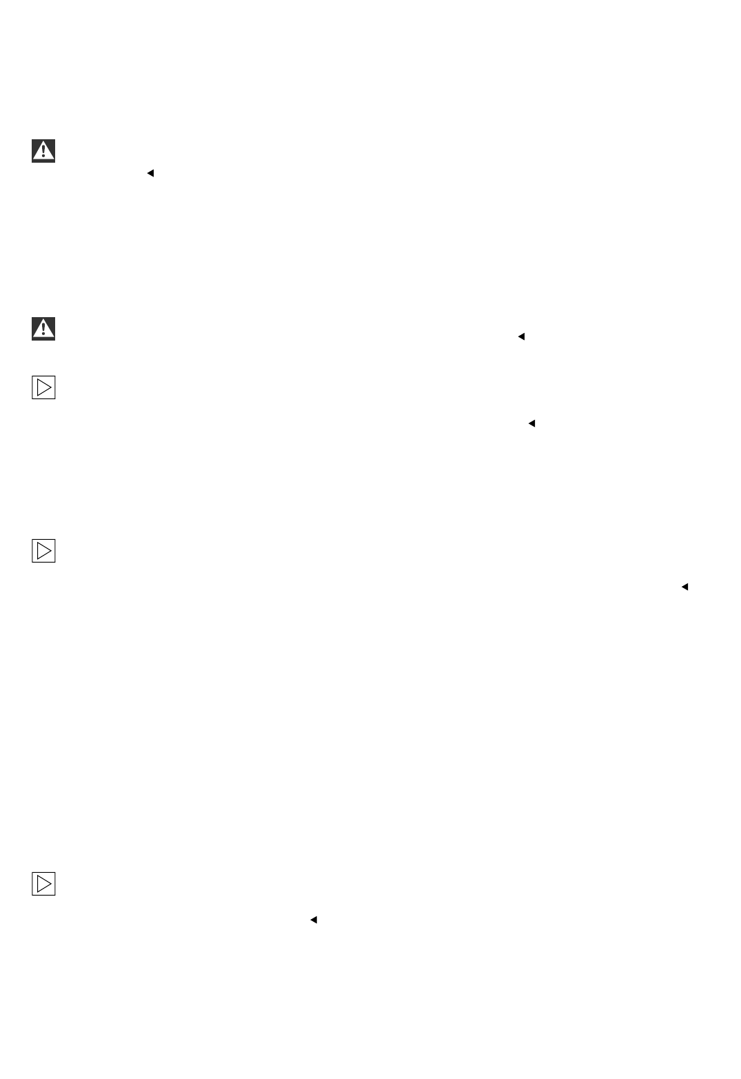
Fold out folded page 2-33.
All lock nuts are to be replaced. All tightening torque values are to be taken from the current repair
instructions and must be observed at all times.
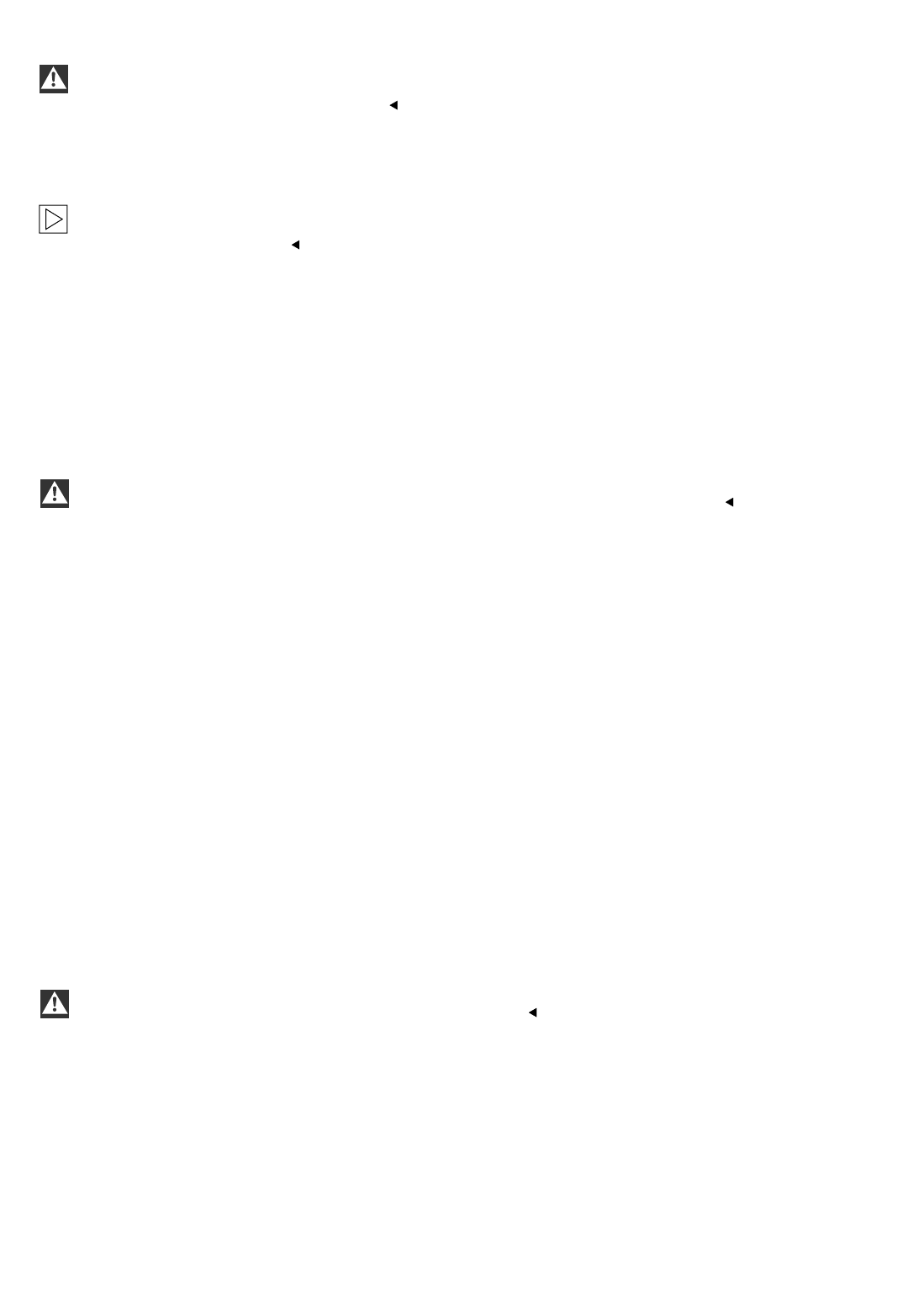
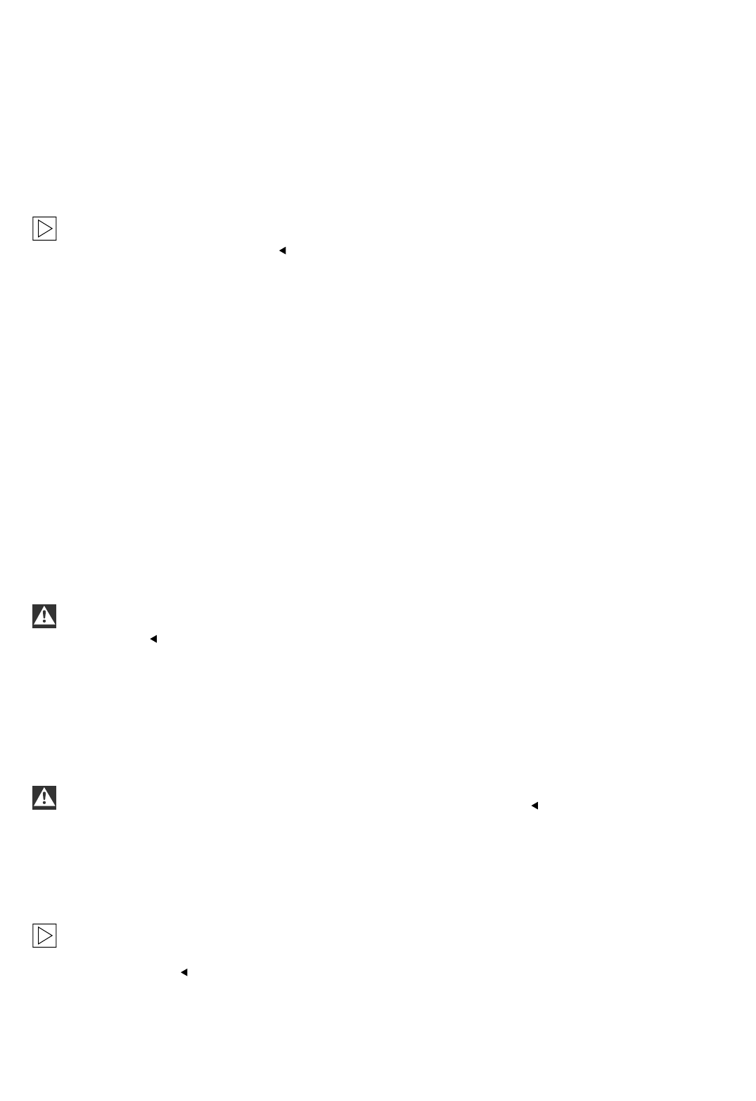
2.2 To install the level sensor at the front right
Cars with an air suspension front axle already have a level sensor.This is to be replaced with the level
sensor supplied with the parts kit.
A
Only for cars without an air suspension front axle.
Mounting points for the level sensor at the front right:
The holder with the fitted level sensor is to be installed using the mounting screw (1) on the control arm (3).
The hole (2) is used as a locking device
The angle joint is mounted on the control arm (3).
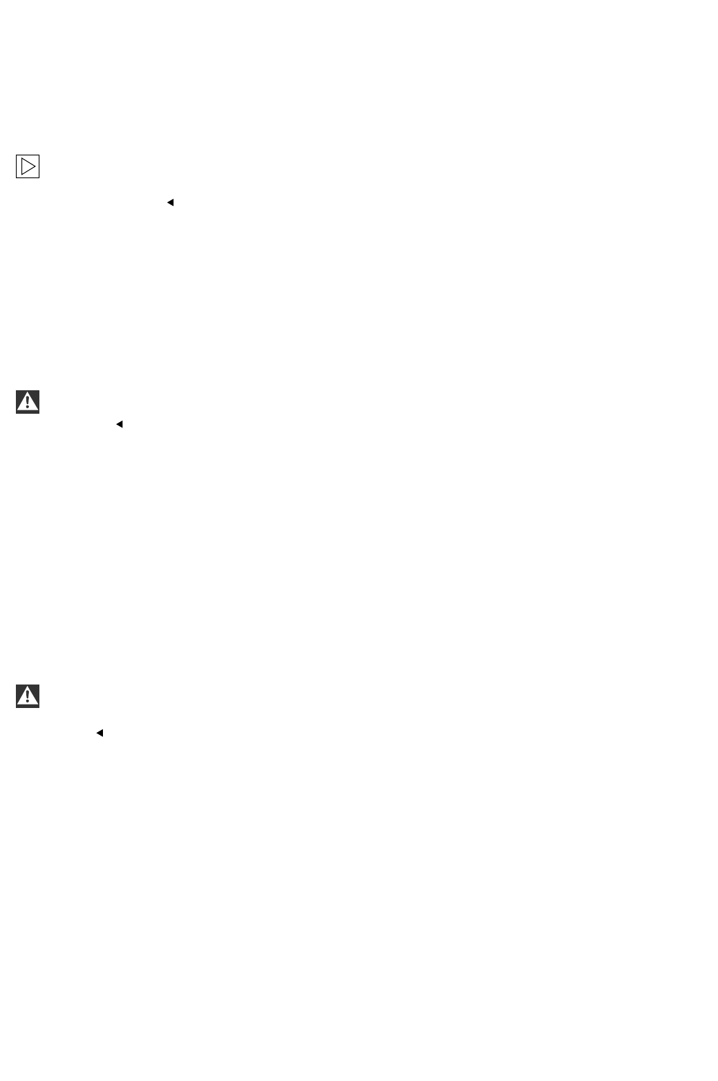
B
Only for cars without an air suspension front axle.
Install the level sensor (4) on the holder (6) using two Allen bolts, M5 x 10 (5).
See the position of the locking device (7) and the threaded sleeve (see magnified view).
C
Only for cars without an air suspension front axle.
Remove the nut SW16 mm from the mounting screw (1) on the control arm (3) and pull out the mounting screw (1).
Position the holder (6) with the level sensor (4) and secure the control arm (3) with the mounting screw (1) and the
lock nut SW 16 mm supplied in the parts kit.
Install the angle joint (8) on the control arm (3) and secure it with a nut SW10 mm.
Connect the angle joint (8) to the lever on the level sensor (4) and secure it with a nut SW10 mm (9).
Only for cars with an air suspension front axle.
Undo the nut SW10 mm (9) and release the angle joint (8). remove the level sensor (4) in the car (see Figure B)
and replace it with the one supplied in the parts kit.
2.3 To install the level sensor at the rear right
Only for cars without a level control system.
D
Mounting points for the level sensor at the rear right:
The holder with the fitted level sensor and the threaded plate is to be installed on the holes (10). Fit the clip
on the holder (11) on the rear axle swinging arm and secure the control rod.
E
Install the level sensor (12) on the holder (14) using two Allen bolts, M5 x 10 (13).
See the position of the threaded sleeve (see magnified view).
F
Fit the threaded plate (15) into the holes (10) in the frame from the rear.
G
Fit the holder (14) wit the level sensor (12) on to the thread and the journal of the threaded plate and secure
it with a lock nut SW 10 mm (16).
Place the clip (17) on the holder (11) for the rear axle swinging arm.
Connect the lever on the level sensor (12) to the holder (11) for the rear axle swinging arm using the control rod
(18). Secure the control rod (18) with the lock nuts SW 10 mm (19 and 20).
EN/2-7

Only for cars with an air suspension front axle.
G
Disconnect the connection plug from the level sensor (12).
Undo the nut SW 10 mm (20) and release the control rod (18).
Undo the nut SW 10 mm (16) and remove the holder (14) with the level sensor (12).
Replace the level sensor fitted in the car with the level sensor supplied with the parts kit.
See the position of the threaded sleeve (see magnified view).
The installation work is to be completed using new lock nuts SW 10 mm (16 and 20), in reverse order.
Do not reconnect the connection plug yet.
2-8/EN
2-33
3
2
1
A
4
5
7
6
B
3
4
8
96
1
C
11
10
D
F 53 0055 EVA F 53 0056 EVA
F 53 0057 EVA F 53 0058 EVA
14
13
12
E
15
10
F
18
14
12
16
19
11
17
20
G
F 53 0059 EVA F 53 0060 EVA
F 53 0061 EVA
2-36/EN
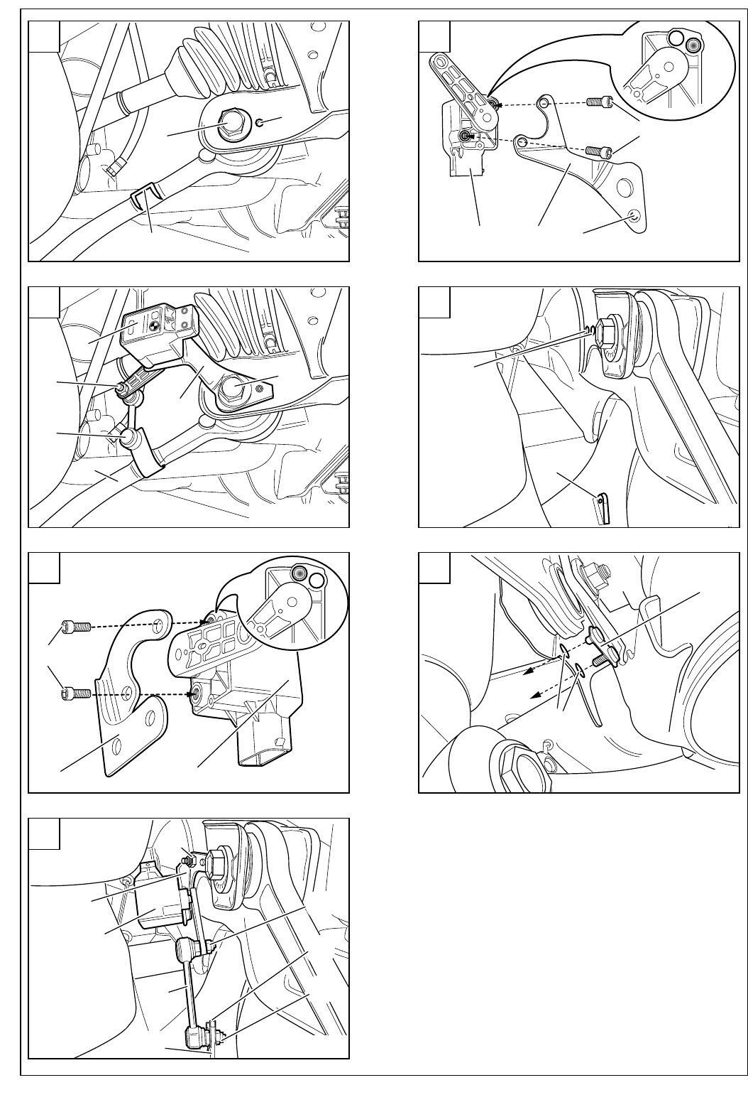
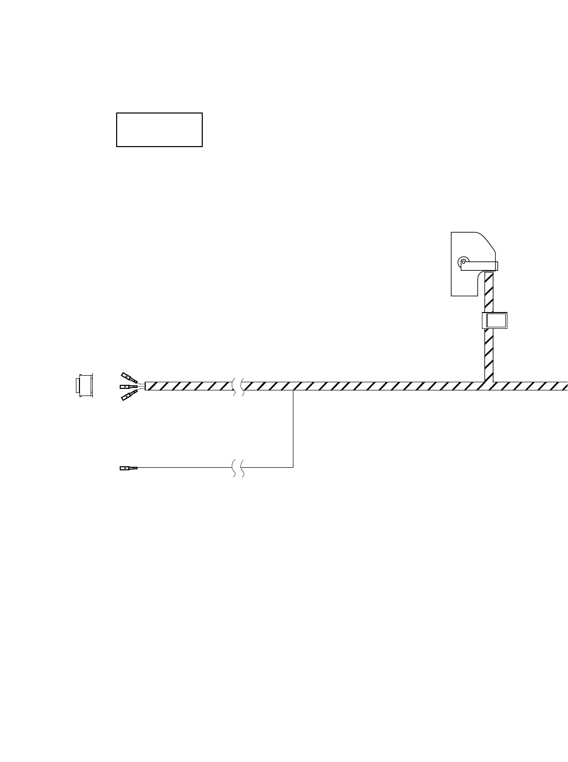
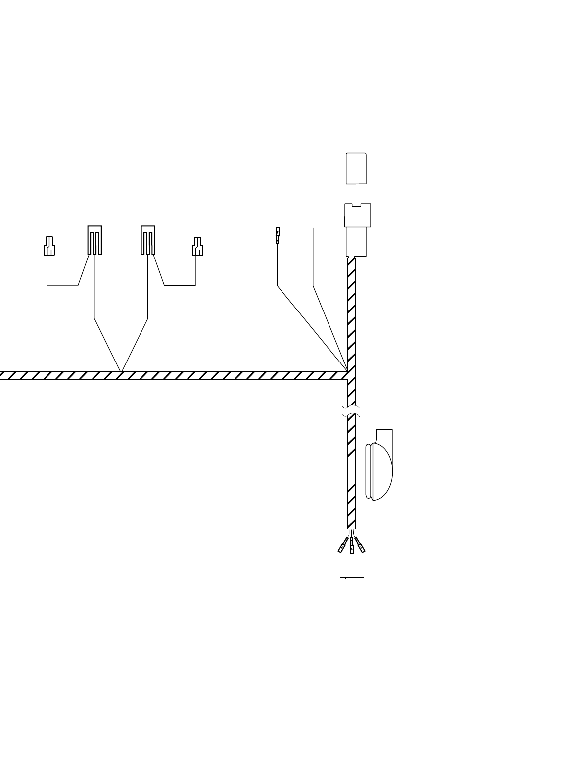
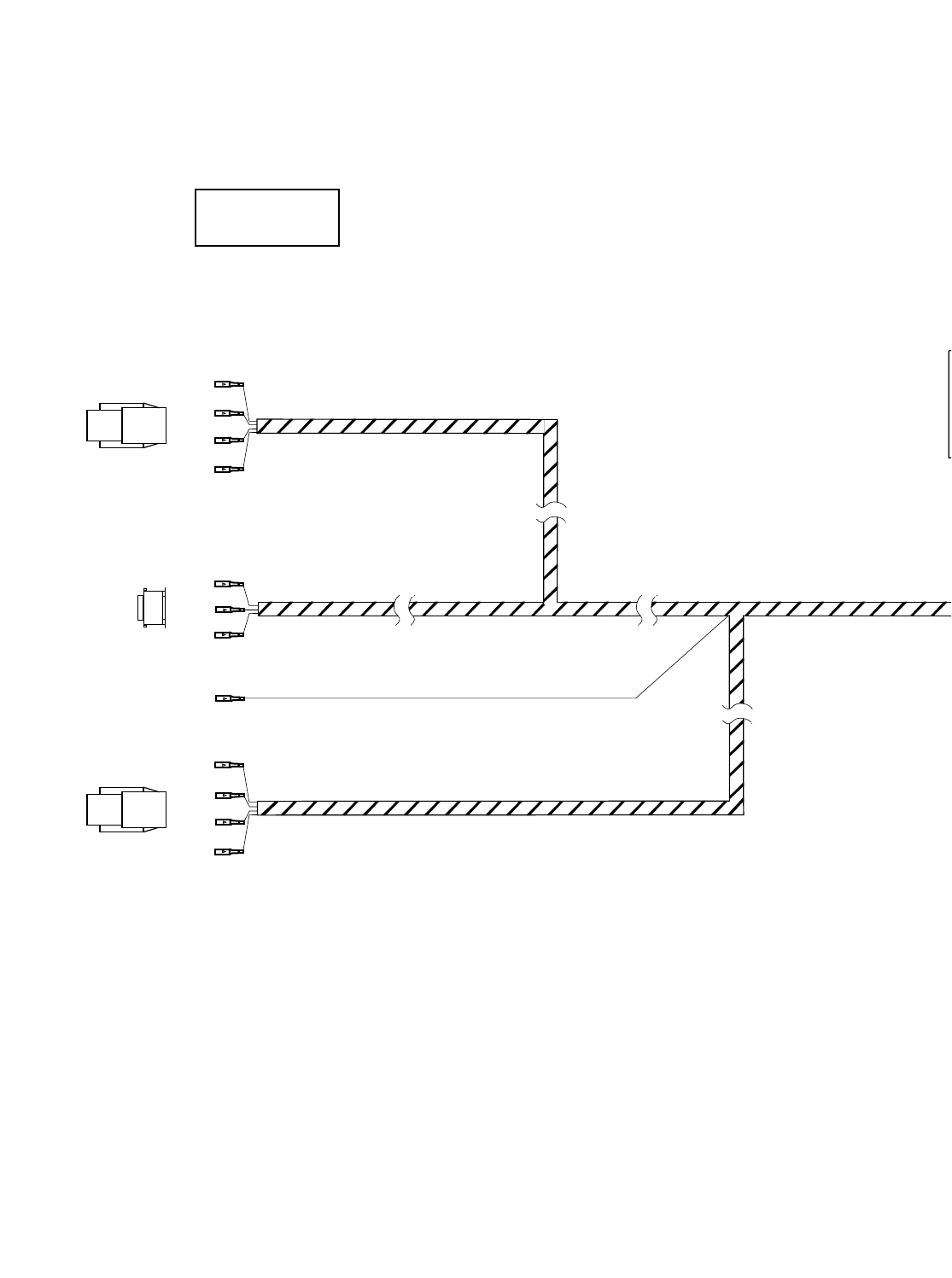
2.4 Connection overview of the xenon wiring harness (ECE cars only)
Fold out folded page 2-43
Item Description Cable colour Connection location in the car Abbreviation /
Slot
A26-pin plug (Bordeaux) - Con. mod. for autom. headlight adjust. cont. sys. X991
B1 Triple joint connector - Connector box behind the glove box X10466*
B2 Joint connector contact white/red/yellow K-bus connector behind the glove box X10116
C1 Triple joint connector - Connector box behind the glove box X1608*
C2 Joint connector contact brown/black Terminal 31 connector behind the glove box X596
DBlade terminal contact yellow/red 54-pin plug on light module on passenger side X10117/27
ECable blue/red 54-pin plug on light module on passenger side X10117/25**
F10-pin plug (black) - Connect to branch G X1S*
G10-pin plug (black) - Connect to branch F X1B*
HCable grommet - Cable passage to boot -
I6-pin plug (black) - Level sensor at rear right X1451
I1 Blade terminal contact grey/white Level sensor at rear right X1451/2
I2 Blade terminal contact grey/brown Level sensor at rear right X1451/3
I3 Blade terminal contact grey/green Level sensor at rear right X1451/6
JBlade terminal contact yellow /white ABS/DSC cont. mod. in the engine compart., front left X1170/18***
K6-pin plug (black) - Level sensor at front right X10275
K1 Blade terminal contact black/white Level sensor at front right X10275/2
K2 Blade terminal contact black/grey Level sensor at front right X10275/3
K3 Blade terminal contact black/green Level sensor at front right X10275/6
Branch E(marked "**") is to be connected to the cable in the car using a double connector.
Branch J(marked "***") is to be connected to plug X1310S at the rear left of the boot on cars with optional
equipment wiring harness from level 2 (see section 1). See section 2.5-G.
The components marked ”*” are only used for this retrofit kit, all other components refer to the application
of the BMW dealer organisation.
Eight cables must be disconnected from the light module C (X10117, 54-pin, black) and fitted with new contacts.
With casing X1B* (branch G), these then provide the connector for branch F(see section 2.5-D).
K
J
K1
K2
K3
A
ECE
2-43
F 53 0062 EVA
I3
I2
I1
I
H
F
G
DEC2C1B1B2
2.5 To install the xenon wiring harness (ECE cars only)
The xenon wiring harness is to be secured using cable ties.
Ensure that cables and other lines are not kinked or damaged when they are being installed in the car and that
they do not impair the freedom of movement of other components.
If the specified pins or chambers are already in use, bridges, double crimps or parallel end stops are to be
used.
Fold out folded page 2-77.
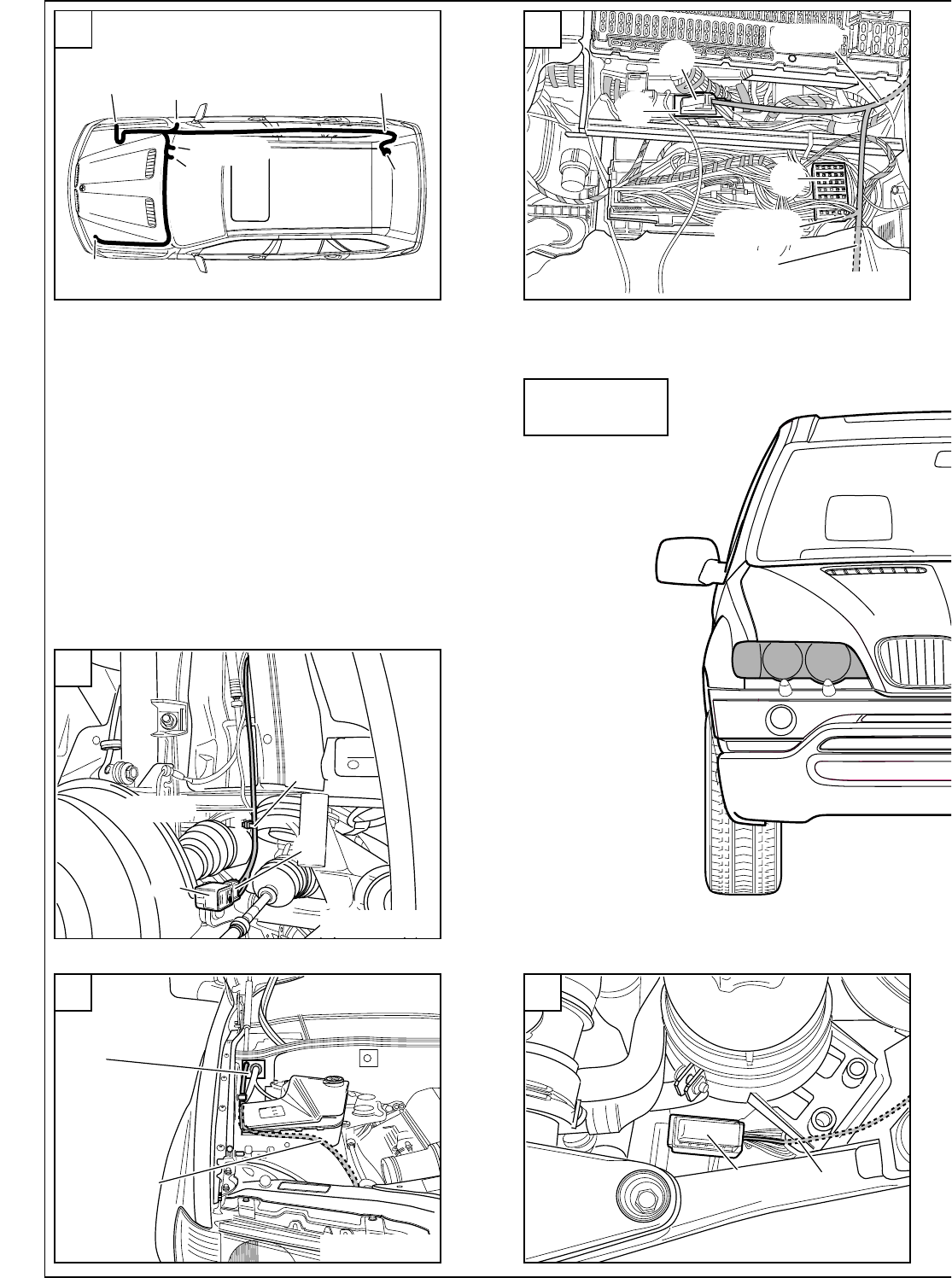
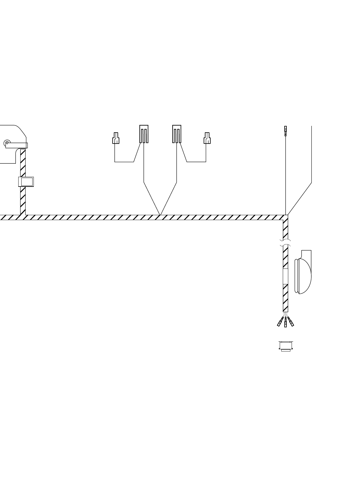
A
Overview of connection points
Branch A(X991, 26-pin plug, Bordeaux) is to be connected to the control module for the automatic headlight
adjustment control system on the module holder behind the glove box.
Branch B1 (triple joint connector X10466*) is to be fitted in the connector box behind the glove box.
Branch B2 (white/red/yellow cable) is to be connected to the K-BUS terminal connector (X10116) behind the glove
box.
Branch C1 (triple joint connector X1608*) is to be fitted in the connector box behind the glove box.
Branch C2 (brown/black cable) is to be connected to the terminal 31 connector (X596) behind the glove box.
Branch D(yellow/red cable) is to be connected to slot 27 in the light module (X10117, 54-pin, black) on the A pillar
on the passenger side.
Branch E(blue/red cable) is to be connected to the blue/red cable from pin 25 on the light module (X10117,
54-pin, black) using a double mini connector.
Branch Fis to be placed next to the light module on the A pillar on the passenger side.
Eight cables must be disconnected from the light module (X10117, 54-pin, black) and fitted with new contacts.
With casing X1B* (branch G), these then provide the connector for branch F(see section 2.5-D).
The rubber grommet His used to seal the cable passage on the floor of the boot.
Cable I1, grey/white cable, is to be connected to slot 2 of branch I(X1451, 6-pin, black), cable I2, grey/brown
cable, to slot 3 and cable I3, grey/green cable, to slot 6. Any cables in the car for the level sensor are to be
repinned (see section 2.5-F). Branch Iis then to be connected to the level sensor at the rear right.
Branch J(yellow/white cable) is to be connected to slot 18 of the ABS/DSC control module in the front left of the
engine compartment in cars with an optional equipment wiring harness up to level 2. In cars with an optional
equipment wiring harness above level 2, there is a yellow/white cable in the boot at the rear left on the 6-pin plug
X1310S on slot 2, which comes from the ABS/DSC control module, slot 18. Connect branch J(yellow/white cable)
to this cable using a double mini connector.
Cable K1, black/white cable, is to be connected to slot 2 of branch K(X10275, 6-pin, black), cable K2, black/grey
cable, to slot 3 and cable K3, black/green cable, to slot 6. Any cables in the car for the air suspension are to be
repinned (see section 2.5-F). Branch Kis then to be connected to the level sensor at the front right.
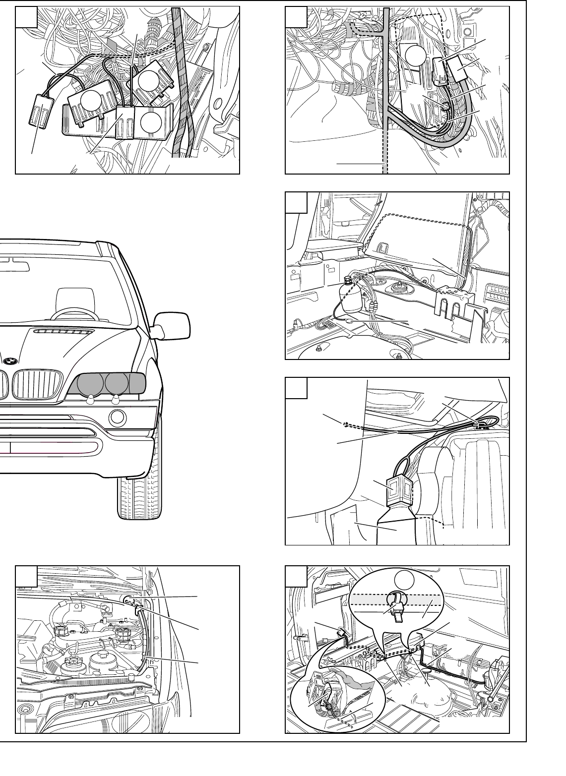
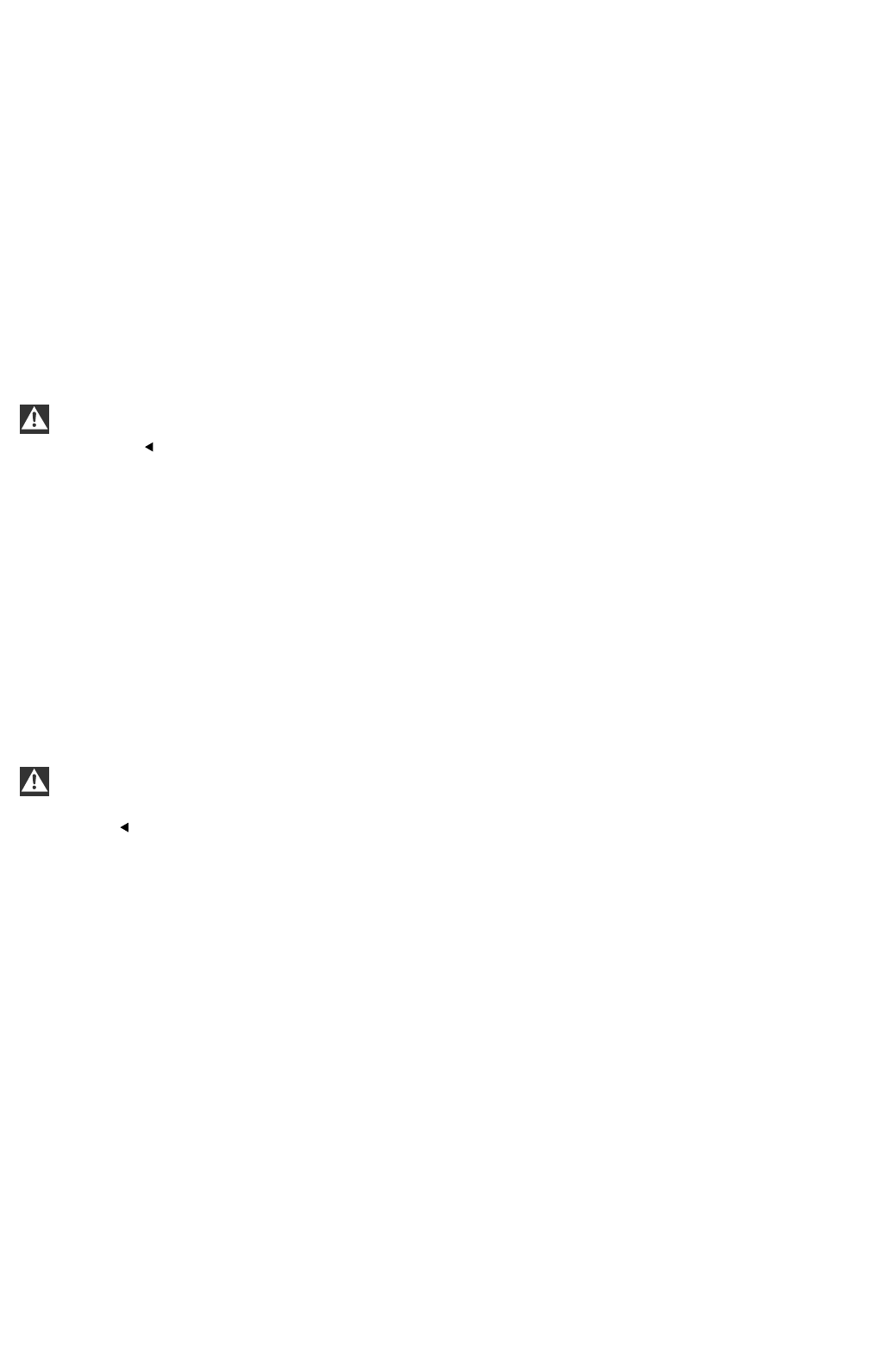
B
Connect the control module for the automatic headlight adjustment control system (1) to the module holder behind
the glove box. Connect branch A(X991, 26-pin plug, Bordeaux) to the control module for the automatic headlight
adjustment control system (1) and secure it.The xenon wiring harness goes to the right and splits near the A pillar.
Branches B1 to I3 go downwards along the vehicle wiring harness, branches B1 to C2 then go to the
connector box (2). Branches Jto K3 go upwards along the vehicle wiring harness.
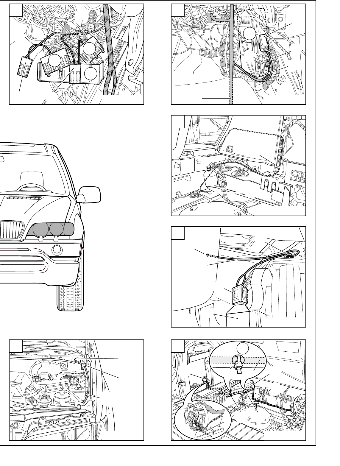
C
Release the connector box (2) and swing it forwards.
Unclip the K bus multiple connector (X10116, white/red/yellow cables) (3) and terminal 31 multiple connector
(X596, brown/black cables) (4).
If there are any unoccupied slots in the multiple connectors X10116 (3) and X596 (4), connect branches B2,
white/red/yellow cable, and C2, brown/black cable, to the corresponding cable colours.
The procedure if all the slots are occupied is described for multiple connector X10116 (3). If necessary
proceed accordingly for multiple connector X596 (4).
Disconnect a white/red/yellow cable from multiple connector X10116 (3) and connect it to the triple connector
X10466* (B1). Connect branch B2, white/red/yellow cable, to the now unoccupied slot on multiple connector
X10116 (3).
Clip multiple connectors X10116 (3), X10466* (B1), X596 (4) and X1608* (C1) into the connector box (2) and mount
the connector box (2) on the module holder.
EN/2-49
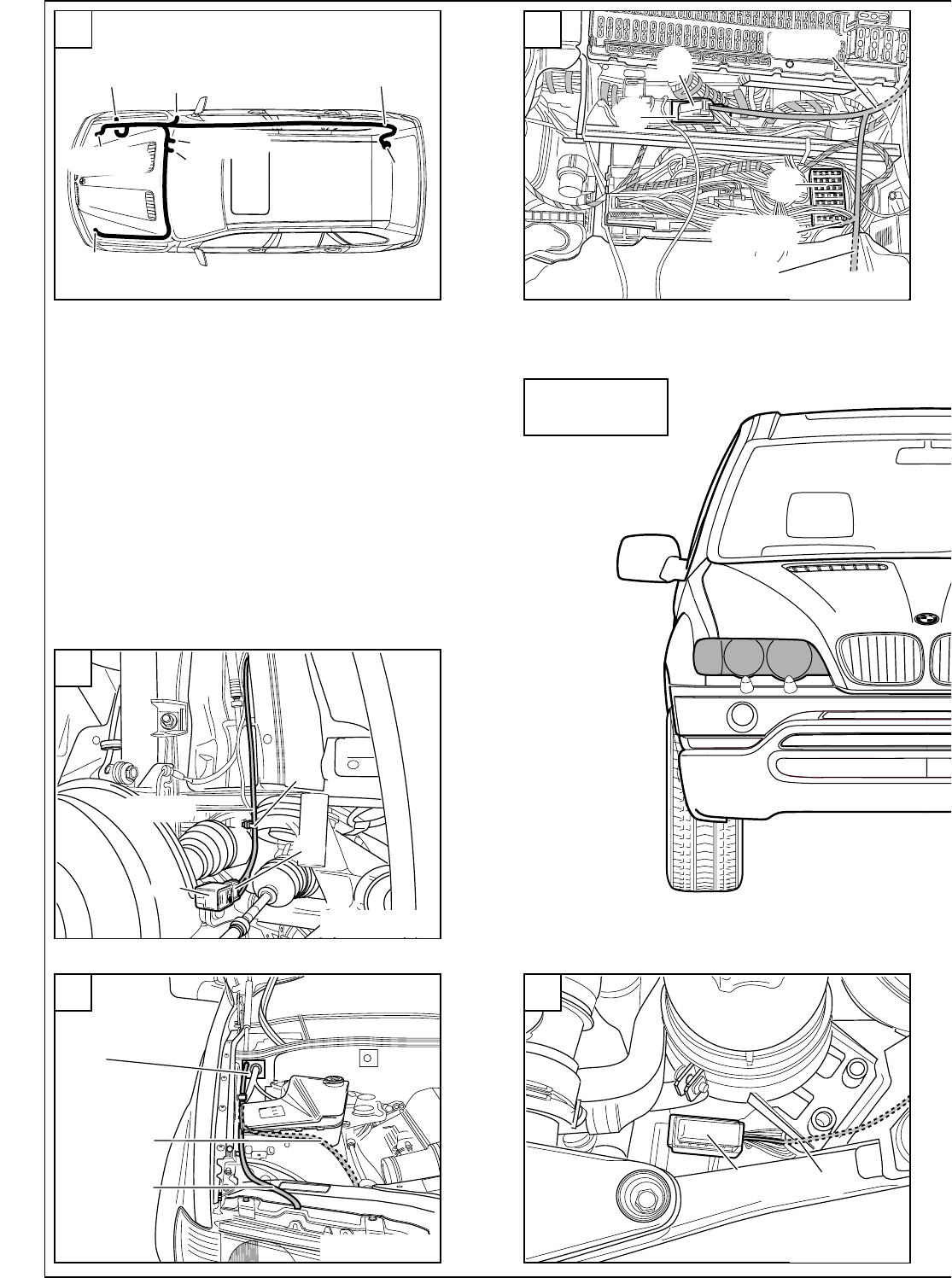
D
Disconnect the 54-pin black plug X10117 (5) from the light module (6) on the A pillar on the passenger side and
take the plug strip off the casing. Lay branches Dand E, yellow/red and blue/red cables, to there. Connect branch
D, yellow/red cable, to slot 27 of the 54-pin plug X10117 (5).
Connect branch E, blue/red cable, to the blue/red cable from slot 25 of the 54-pin plug X10117 (5) using a double
mini connector from the parts kit (7).
Ensure that the casing and plug strip can be assembled and connected to the light module (6) after the mini
connector (7) has been connected.
Disconnect the following cables from the plug strips of plug X10117 (5), fit the contact parts to them supplied in
the parts kit and connect them to the 10-pin casing (G).
Two yellow/brown and two blue/brown cables are to be disconnected but must not be mixed up. Keep to the
order described to avoid confusion.
First disconnect the following four cables:
Slot 2, blue/red cable;
Slot 3, blue/brown cable;
Slot 4, yellow/red cable;
Slot 5, yellow/brown cable.
Remove the contact parts from these cables, strip the cables and fit the contact parts supplied in the parts kit to
them.
Connect the cables as follows to the black 10-pin plug X1B* (G) supplied with the kit:
Connect the blue/red cable to slot 1 of the black 10-pin plug X1B* (G).
Connect the blue/brown cable to slot 2 of the black 10-pin plug X1B* (G).
Connect the yellow/red cable to slot 3 of the black 10-pin plug X1B* (G)
Connect the yellow/brown cable to slot 4 of the black 10-pin plug X1B* (G)
Now disconnect the following four cables:
Slot 20, blue/black cable;
Slot 21, blue/brown cable;
Slot 22, yellow/black cable;
Slot 23, yellow/brown cable.
Remove the contact parts from these cables, strip the cables and fit the contact parts supplied in the parts kit to
them.
Connect the cables as follows to the black 10-pin plug X1B* (G) supplied with the kit:
Connect the blue/black cable to slot 7 of the black 10-pin plug X1B* (G).
Connect the blue/brown cable to slot 8 of the black 10-pin plug X1B* (G).
Connect the yellow/black cable to slot 9 of the black 10-pin plug X1B* (G)
Connect the yellow/brown cable to slot 10 of the black 10-pin plug X1B* (G)
Connect the 10-pin black plug X1B* (G) to branch Fof the xenon wiring harness and stow the plug connector so
that it does not interfere with any other components.
Assemble the 54-pin plug X10117 (5), connect it to the light module (6) and secure it.
Branches I1 to I3 go further back along the vehicle wiring harness towards the rear.
E
In cars with a vehicle wiring harness above level 2 (see section 1), branch J(yellow/white cable) on the xenon
wiring harness goes parallel to branches I1 to I3 into the boot.
Lay branches I1 to I3 (grey/white, grey/brown and grey/green cables) along the right-hand sill wiring harness to
the rear, along the vehicle wiring harness behind the right-hand boot trim and then along the vehicle wiring
harness to the floor of the boot.
Remove the 20 mm sealing stopper from the floor of the boot (the hole in Figure Eis already sealed with the
grommet (H)), deburr the hole and treat it with the normal BMW anti-corrosion coatings.
Place grommet Hon cables I1 to I3, grey/white, grey/brown and grey/green cables, and thread cables I1 to I3
through the holes to the underside of the car.
The rear axle is beneath the hole.
2-50/EN
F
Lay branches I1 to I3 (grey/white, grey/brown and grey/green cables) forwards a little on the rear axle, secure them
to the cable holder (8) and lay them to the level sensor (9).
Only for cars without a level control system:
Connect cables I1 to I3 on the xenon wiring harness as follows:
Connect branch I1, grey/white cable, to slot 2 of the black 6-pin plug X1451 (I).
Connect branch I2, grey/brown cable, to slot 3 of the black 6-pin plug X1451 (I).
Connect branch I3, grey/green cable, to slot 6 of the black 6-pin plug X1451 (I).
Seal slots 1, 4 and 5 using the supplied blind grommets.
Only for cars with a level control system:
Cars with a level control system already have a branch of the vehicle wiring harness to the level sensor at the
rear right and a black 6-pin plug X1451.
Disconnect the three cables in the car (yellow/brown, yellow/grey and yellow/white or yellow/black) and connect
them as follows to the black 6-pin plug X1451 (I) supplied with the parts kit:
On cars with air suspension on one axle:
Connect the yellow/black cable to slot 1 of the black 6-pin plug X1451 (I).
Connect the yellow/brown cable to slot 4 of the black 6-pin plug X1451 (I).
Connect the yellow/grey cable to slot 5 of the black 6-pin plug X1451 (I).
On cars with air suspension on both axles:
Connect the yellow/brown cable to slot 1 of the black 6-pin plug X1451 (I).
Connect the yellow/grey cable to slot 4 of the black 6-pin plug X1451 (I).
Connect the yellow/white cable to slot 5 of the black 6-pin plug X1451 (I).
Connect cables I1 to I3 on the xenon wiring harness as follows:
Connect branch I1, grey/white cable, to slot 2 of the black 6-pin plug X1451 (I).
Connect branch I2, grey/brown cable, to slot 3 of the black 6-pin plug X1451 (I).
Connect branch I3, grey/green cable, to slot 6 of the black 6-pin plug X1451 (I).
All cars:
Connect the black 6-pin plug X1451 (I) to the level sensor (9).
Seal the hole in the floor of the boot with the grommet (H).
Ensure that the grommet (H) is fitted so that the car is watertight and that the cables do not interfere with any
other components.
G
Only for cars with an optional equipment wiring harness above level 2 (see section 1):
Lay branch J, yellow/white cable, parallel to branches I1 to I3 (see Figure E) into the boot. Lay branch Jon the
wiring harness along the battery positive distributor, continue behind the boot trim (10) to the 6-pin plug X1310S
(11). Cut branch J, yellow/white cable, to size and connect it to the yellow/white cable from slot 2 of the 6-pin plug
X1310S (11) using the double mini connector supplied in the parts kit (see magnified view).
Drill two holes in the boot trim (10) and secure branch Jto them using cable ties (12) (see magnified view).
Ensure that the spare wheel cannot chafe on branch J (yellow/white cable).
H, I
Only for cars with an optional equipment wiring harness up to level 2 (see section 1):
Lay branch J, yellow/white cable, along the vehicle wiring harness behind the module carrier in the passenger side
footwell to the left-hand side of the car, through the additional passage hole in the front bulkhead grommet (13)
and the grommet (14) into the engine compartment and then along the vehicle wiring harness on the inside wing
to the 42-pin blue plug X1170 (15) on the ABS/DSC control module.
The left front bulkhead grommet (13) does not have an additional passage hole for retrofit wiring harnesses in
the first cars in the series. In this case the cable Jis to be laid along vehicle wiring harness through the front
bulkhead grommet (13).
EN/2-51
Disconnect the 42-pin blue plug X1170 (15) from the ABS/DSC control module, release the plug strip, remove the
blind stopper from slot 18 and connect branch J, yellow/white cable, to slot 18.
Engage the plug strip, connect the 42-pin blue plug X1170 (15) to the ABS/DSC control module and secure it.
J
Lay branches K1 to K3, black/white, black/grey and black/green cables, through the additional passage hole in the
right front bulkhead grommet near the electrics box and then through the grommet (16) into the engine compart-
ment. Lay branches K1 to K3 along the vehicle wiring harness on the inside wing towards the front and to the
engine near the washer water tank.
The right front bulkhead grommet does not have an additional passage hole for retrofit wiring harnesses in
the first cars in the series. In this case the cables K1 to K3 are to be laid along vehicle wiring harness through the
front bulkhead grommet.
K
Lay branches K1 to K3 parallel to the cables for the ABS sensor into the wheel arch and connect them to the
black 6-pin plug X10275 (K) as follows:
Cars without air suspension on both axles only:
Connect branch K1, black/white cable, to slot 2 of the black 6-pin plug X10275 (K).
Connect branch K2, black/white cable, to slot 3 of the black 6-pin plug X10275 (K).
Connect branch K3, black/white cable, to slot 6 of the black 6-pin plug X10275 (K).
Seal slots 1, 4 and 5 with the blind grommets supplied.
Cars with air suspension on both axles only:
Two black/white and two black/grey cables are used. it is therefore essential to keep to the order described to
avoid confusion.
There is already a black 6-pin plug X10275 in the car. Disconnect the three cables (black/brown, black/grey and
black/white) from these plugs and connect them to the black 6-pin plug X10275 (K) supplied in the parts kit as
follows:
Connect the black/brown cable for the air suspension to slot 1 of the black 6-pin plug X10275 (K).
Connect the black/grey cable for the air suspension to slot 4 of the black 6-pin plug X10275 (K).
Connect the black/white cable for the air suspension to slot 5 of the black 6-pin plug X10275 (K).
Connect the cables on the xenon wiring harness as follows:
Connect branch K1, black/white cable, to slot 2 of the black 6-pin plug X10275 (K).
Connect branch K2, black/white cable, to slot 3 of the black 6-pin plug X10275 (K).
Connect branch K3, black/white cable, to slot 6 of the black 6-pin plug X10275 (K).
All cars:
Connect the black 6-pin plug X10275 (K) to the level sensor at the front right (17) and secure the wiring harness to
the hole in the axle with a cable tie (18).
Check again that the entire xenon wiring harness has been installed in such a way that none of the cables
are kinked or damaged and that it has been secured with the cable ties so that it does not interfere with any other
components.
2-52/EN
15 J
I
B1-C2
D-I3
2
1
AJ-K3
B
A
B1-C2
D,E
F, GK1-K3 I1-I3
H
J
A
17
18
K1-K3
K
K
16
K1-K3
J
F 53 0063 EVA
F 53 0073 EVA
F 53 0072 EVA F 53 0071 EVA
F 53 0064 EVA
ECE
2-77
13
14
J
H
10
12 J
J
11
11
J
1212
10
G
2
34
B1 C1
B2
C2
C
6
7
5
F, G
D
I1-I3
E
D
E
I1-I3
E
8
9
I
H
I1-I3
F
F 53 0070 EVA F 53 0090 EVA
F 53 0068 EVA
F 53 0067 EVA
F 53 0066 EVAF 53 0065 EVA
F 53 0054 EVA

EN/2-81
2.6 Connection overview of the xenon wiring harness (ECE cars only)
Fold out folded page 2-95
Item Description Cable colour Connection location in the car Abbreviation /
Slot
A26-pin plug (Bordeaux) - Con. mod. for autom. headlight adjust. cont. sys. X991
B1 Triple joint connector - Connector box behind the glove box X10466*
B2 Joint connector contact white/red/yellow K-bus connector behind the glove box X10116
C1 Triple joint connector - Connector box behind the glove box X1608*
C2 Joint connector contact brown/black Terminal 31 connector behind the glove box X596
DBlade terminal contact yellow/red 54-pin plug on light module on passenger side X10117/27
EBlade terminal contact blue/red 54-pin plug on light module on passenger side X10117/25**
FCable grommet - Cable passage to boot -
G6-pin plug (black) - Level sensor at rear right X1451
G1 Blade terminal contact grey/white Level sensor at rear right X1451/2
G2 Blade terminal contact grey/brown Level sensor at rear right X1451/3
G3 Blade terminal contact grey/green Level sensor at rear right X1451/6
H4-pin plug (natural) - Servo motor for left headlight X1034
H1 Blade terminal contact yellow/red Servo motor for left headlight X1034/1
H2 Blade terminal contact yellow/brown Servo motor for left headlight X1034/2
H3 Blade terminal contact blue/red Servo motor for left headlight X1034/3
H4 Blade terminal contact blue/brown Servo motor for left headlight X1034/4
IBlade terminal contact yellow/white ABS/DSC cont. mod. in the engine compart., front left X1170/18***
J6-pin plug (black) - Level sensor at front right X10275
J1 Blade terminal contact black/white Level sensor at front right X10275/2
J2 Blade terminal contact black/grey Level sensor at front right X10275/3
J3 Blade terminal contact black/grey Level sensor at front right X10275/6
K4-pin plug (natural) - Servo motor for right headlight X1035
K1 Blade terminal contact yellow/black Servo motor for right headlight X1035/1
K2 Blade terminal contact yellow/brown Servo motor for right headlight X1035/2
K3 Blade terminal contact blue/black Servo motor for right headlight X1035/3
K4 Blade terminal contact blue/brown Servo motor for right headlight X1035/4

Branch E(marked "**") is to be connected to the cable in the car using a double connector.
Branch I(marked "***") is to be connected to plug X1310S at the rear left of the boot on cars with optional
equipment wiring harness from level 2. See section 2.7-G.
The components marked ”*” are only used for this retrofit kit, all other components refer to the application of
the BMW dealer organisation.
2-82/EN
JJ1
K3
K2
K1
K4
J2
J3
I
H2
H1
H4
H3
K
H
USA
2-95
F 53 0074 EVA
G3
G2
G1
G
F
D
C2C1B1B2A E
2.7 To install the xenon wiring harness (US cars only)
The xenon wiring harness is to be secured using cable ties.
Ensure that cables and other lines are not kinked or damaged when they are being installed in the car and that
they do not impair the freedom of movement of other components.
If the specified pins or chambers are already in use, bridges, double crimps or parallel end stops are to be
used.
Fold out folded page 2-129
A
Overview of connection points
Branch A(X991, 26-pin plug, Bordeaux) is to be connected to the control module for the automatic headlight
adjustment control system on the module holder behind the glove box.
Branch B1 (triple joint connector X10466*) is to be fitted in the connector box behind the glove box.
Branch B2 (white/red/yellow cable) is to be connected to the K-BUS terminal connector (X10116) behind the glove
box.
Branch C1 (triple joint connector X1608*) is to be fitted in the connector box behind the glove box.
Branch C2 (brown/black cable) is to be connected to the terminal 31 connector (X596) behind the glove box.
Branch D(yellow/red cable) is to be connected to slot 27 in the light module (X10117, 54-pin, black) on the A pillar
on the passenger side.
Branch E(blue/red cable) is to be connected to the blue/red cable from pin 25 on the light module (X10117,
54-pin, black) using a double mini connector.
The rubber grommet (F) is used to seal the cable passage on the floor of the boot.
Cable G1, grey/white cable, is to be connected to slot 2 of branch G(X1451, 6-pin, black), cable G2, grey/brown
cable, to slot 3 and cable G3, grey/green cable, to slot 6. Any cables in the car for the level sensor are to be
repinned (see section 2.7-F). Branch Gis then to be connected to the level sensor at the rear right.
Cable H1, yellow/red cable, is to be connected to slot 1 of branch H(X1034, 4-pin, natural), cable H2,
yellow/brown cable, to slot 2, cable H3, blue/red cable, to slot 3 and cable H4, blue/brown cable, to slot 4. Branch
His to be connected to the servo motor on the left Xenon headlight.
Branch I(yellow/white cable) is to be connected to slot 18 of the ABS/DSC control module in the front left of the
engine compartment in cars with an optional equipment wiring harness up to level 2. In cars with an optional
equipment wiring harness above level 2, there is a yellow/white cable in the boot at the rear left on the 6-pin plug
X1310S on slot 2, which comes from the ABS/DSC control module, slot 18. Connect branch I(yellow/white cable)
to this cable using a double mini connector.
Cable J1, black/white cable, is to be connected to slot 2 of branch J (X10275, 6-pin, black), cable J2, black/grey
cable, to slot 3 and cable J3, black/green cable, to slot 6. Any cables in the car for the air suspension are to be
repinned (see section 2.7-F). Branch Jis then to be connected to the level sensor at the front right.
Cable K1, yellow/black cable, is to be connected to slot 1 of branch K (X1035, 4-pin, natural), cable K2,
yellow/brown cable, to slot 2, cable K3, blue/black cable, to slot 3 and cable K4, blue/brown cable, to slot 4.
Branch Kis to be connected to the servo motor on the right Xenon headlight.
B
Connect the control module for the automatic headlight adjustment control system (1) to the module holder behind
the glove box. Connect branch A(X991, 26-pin plug, Bordeaux) to the control module for the automatic headlight
adjustment control system (1) and secure it.The xenon wiring harness goes to the right and splits near the A pillar.
Branches B1 to G3 go downwards along the vehicle wiring harness, branches B1 to C2 then go to the
connector box (2).
Branches Hto K4 go upwards along the vehicle wiring harness.
C
Release the connector box (2) and swing it forwards.
Unclip the Kbus multiple connector (X10116, white/red/yellow cables) (3) and terminal 31 multiple connector
(X596, brown/black cables) (4).
If there are any unoccupied slots in the multiple connectors X10116 (3) and X596 (4), connect branches B2,
white/red/yellow cable, and C2, brown/black cable, to the corresponding cable colours.
The procedure if all the slots are occupied is described for multiple connector X10116 (3). If necessary
proceed accordingly for multiple connector X596 (4).
Disconnect a white/red/yellow cable from multiple connector X10116 (3) and connect it to the triple connector
X10466* (B1). Connect branch B2, white/red/yellow cable, to the now unoccupied slot on multiple connector
X10116 (3).
EN/2-101
Clip multiple connectors X10116 (3), X10466* (B1), X596 (4) and X1608* (C1) into the connector box (2) and mount
the connector box (2) on the module holder.
D
Disconnect the 54-pin black plug X10117 (5) from the light module (6) on the A pillar on the passenger side and
take the plug strip off the casing. Lay branches Dand E, yellow/red and blue/red cables, to there. Connect branch
D, yellow/red cable, to slot 27 of the 54-pin plug X10117 (5).
Connect branch E, blue/red cable, to the blue/red cable from slot 25 of the 54-pin plug X10117 (5) using a double
mini connector from the parts kit (7).
Ensure that the casing and plug strip can be assembled and connected to the light module (6) after the mini
connector (7) has been connected.
Assemble the black 54-pin plug (5), connect it to the light module (6) and secure it.
Branches G1 to G3 go further back along the vehicle wiring harness towards the rear.
E
In cars with a vehicle wiring harness above level 2 (see section 1), branch I(yellow/white cable) on the xenon
wiring harness goes parallel to branches G1 to G3 into the boot.
Lay branches G1 to G3 (grey/white, grey/brown and grey/green cables) along the right-hand sill wiring harness
to the rear, along the vehicle wiring harness behind the right-hand boot trim and then along the vehicle wiring
harness to the floor of the boot.
Remove the 20 mm sealing stopper from the floor of the boot (the hole in Figure E is already sealed with the
grommet (F)), deburr the hole and treat it with the normal BMW anti-corrosion coatings.
Place grommet Fon cables G1 to G3, grey/white, grey/brown and grey/green cables, and thread cables G1 to G3
through the holes to the underside of the car.
The rear axle is beneath the hole.
F
Lay branches G1 to G3 (grey/white, grey/brown and grey/green cables) forwards a little on the rear axle, secure
them to the cable holder (8) and lay them to the level sensor (9).
Only for cars without a level control system:
Connect cables G1 to G3 on the xenon wiring harness as follows:
Connect branch G1, grey/white cable, to slot 2 of the black 6-pin plug X1451 (G).
Connect branch G2, grey/brown cable, to slot 3 of the black 6-pin plug X1451 (G).
Connect branch G3, grey/green cable, to slot 6 of the black 6-pin plug X1451 (G).
Seal slots 1, 4 and 5 using the supplied blind grommets.
Only for cars with a level control system:
Cars with a level control system already have a branch of the vehicle wiring harness to the level sensor at the
rear right and a black 6-pin plug X1451.
Disconnect the three cables in the car (yellow/brown, yellow/grey and yellow/white or yellow/black) and connect
them as follows to the black 6-pin plug X1451 (G) supplied with the parts kit:
On cars with air suspension on one axle:
Connect the yellow/black cable to slot 1 of the black 6-pin plug X1451 (G).
Connect the yellow/brown cable to slot 4 of the black 6-pin plug X1451 (G).
Connect the yellow/grey cable to slot 5 of the black 6-pin plug X1451 (G).
On cars with air suspension on both axles:
Connect the yellow/brown cable to slot 1 of the black 6-pin plug X1451 (G).
Connect the yellow/grey cable to slot 4 of the black 6-pin plug X1451 (G).
Connect the yellow/white cable to slot 5 of the black 6-pin plug X1451 (G).
2-102/EN
Connect cables G1 to G3 on the xenon wiring harness as follows:
Connect branch G1, grey/white cable, to slot 2 of the black 6-pin plug X1451 (G).
Connect branch G2, grey/brown cable, to slot 3 of the black 6-pin plug X1451 (G).
Connect branch G3, grey/green cable, to slot 6 of the black 6-pin plug X1451 (G).
All cars:
Connect the black 6-pin plug X1451 (G) to the level sensor.
Seal the hole in the floor of the boot with the grommet (F).
Ensure that the grommet (F) is fitted so that the car is watertight and that the cables do not interfere with any
other components.
G
Only for cars with an optional equipment wiring harness above level 2 (see section 1):
Lay branch I, yellow/white cable, parallel to branches G1 to G3 (see Figure E) into the boot. Lay branch Ion the
wiring harness along the battery positive distributor, continue behind the boot trim (10) to the 6-pin plug X1310S
(11). Cut branch I, yellow/white cable, to size and connect it to the yellow/white cable from slot 2 of the 6-pin plug
X1310S (11) using the double mini connector supplied in the parts kit (see magnified view).
Drill two holes in the boot trim (10) and secure branch Ito them using cable ties (12) (see magnified view).
Ensure that the spare wheel cannot chafe on branch I(yellow/white cable).
H, I
Figures H and I shows the cable positions for cars with an optional equipment wiring harness up to level 2
(see section 1). In cars with an optional equipment wiring harness above level 2, branch I, yellow/white cable, is to
be connected to the 6-pin plug X1310S at the rear left of the boot (see Figure G).
Lay branches H1 to H4, yellow/red, yellow/brown, blue/red and blue/brown cables, and branch I, yellow/white
cable(branch Ionly on cars with an optional equipment wiring harness up to level 2), along the vehicle wiring
harness behind the module holder in the passenger footwell to the left-hand side of the car, through the additional
passage hole in the front bulkhead grommet (13) and through the grommet (14) into the engine compartment.
Lay the cables along the vehicle wiring harness on the inside wing to near the left headlight.
The left front bulkhead grommet (13) does not have an additional passage hole for retrofit wiring harnesses in
the first cars in the series. In this case the cables H1 to H4 and I(only on cars with an optional equipment wiring
harness up to level 2) are to be laid along vehicle wiring harness through the front bulkhead grommet (13).
Connect branches H1 to H4 to the casing H(X1034, 4-pin. natural) as follows:
Connect branch H1, yellow/red cable, to slot 1 of the 4-pin plug X1034 (H).
Connect branch H2, yellow/brown cable, to slot 2 of the 4-pin plug X1034 (H).
Connect branch H3, blue/red cable, to slot 3 of the 4-pin plug X1034 (H).
Connect branch H4, blue/brown cable, to slot 4 of the 4-pin plug X1034 (H).
After the xenon headlight has been installed, the 4-pin plug X1034 (H) is to be connected to the servo motor for
the headlight.
Disconnect the 42-pin blue plug X1170 (15) from the ABS/DSC control module, release the plug strip, remove the
blind stopper from slot 18 and connect branch I, yellow/white cable, to slot 18.
Engage the plug strip, connect the 42-pin blue plug X1170 (15) to the ABS/DSC control module and secure it.
J
Lay branches J1 to J3, black/white, black/grey and black/green cables, and cables K1 to K4, yellow/black,
yellow/brown, blue/black and blue/brown cables, through the additional passage hole in the right front bulkhead
grommet near the electrics box and then through the grommet (16) into the engine compartment. Lay branches J1
to J3 and K1 to K4 along the vehicle wiring harness on the inside wing towards the front.
The right front bulkhead grommet does not have an additional passage hole for retrofit wiring harnesses in
the first cars in the series. In this case the cables J1 to J3 and K1 to K4 are to be laid along vehicle wiring
harness through the front bulkhead grommet.
Lay branches J1 to J3 to the engine near the washer water tank.
EN/2-103
Lay branches K1 to K4 further along the vehicle wiring harness to the plugs for the right headlight and connect
them to the supplied casing K(X1034, 4-pin natural) as follows:
Connect branch K1, yellow/black cable, to slot 1 of the 4-pin plug X1035 (K).
Connect branch K2, yellow/brown cable, to slot 2 of the 4-pin plug X1035 (K).
Connect branch K3, blue/black cable, to slot 3 of the 4-pin plug X1035 (K).
Connect branch K4, blue/brown cable, to slot 4 of the 4-pin plug X1035 (K).
After the xenon headlight has been installed, the 4-pin plug X1035 (K) is to be connected to the servo motor for
the headlight.
K
Lay branches J1 to J3 parallel to the cables for the ABS sensor into the wheel arch and connect them to the black
6-pin plug X10275 (J) as follows:
Cars without air suspension on both axles only:
Connect branch J1, black/white cable, to slot 2 of the black 6-pin plug X10275 (J).
Connect branch J2, black/white cable, to slot 3 of the black 6-pin plug X10275 (J).
Connect branch J3, black/white cable, to slot 6 of the black 6-pin plug X10275 (J).
Seal slots 1, 4 and 5 with the blind grommets supplied.
Cars with air suspension on both axles only:
Two black/white and two black/grey cables are used. it is therefore essential to keep to the order described to
avoid confusion.
There is already a black 6-pin plug X10275 in the car. Disconnect the three cables (black/brown, black/grey and
black/white) from these plugs and connect them to the black 6-pin plug X10275 (J) supplied in the parts kit as
follows:
Connect the black/brown cable for the air suspension to slot 1 of the black 6-pin plug X10275 (J).
Connect the black/grey cable for the air suspension to slot 4 of the black 6-pin plug X10275 (J).
Connect the black/white cable for the air suspension to slot 5 of the black 6-pin plug X10275 (J).
Connect the cables on the xenon wiring harness as follows:
Connect branch J1, black/white cable, to slot 2 of the black 6-pin plug X10275 (J).
Connect branch J2, black/white cable, to slot 3 of the black 6-pin plug X10275 (J).
Connect branch J3, black/white cable, to slot 6 of the black 6-pin plug X10275 (J).
All cars:
Connect the black 6-pin plug X10275 (J) to the level sensor at the front right (17) and secure the wiring harness to
the hole in the axle with a cable tie (18).
Check again that the entire xenon wiring harness has been installed in such a way that none of the cables
are kinked or damaged and that it has been secured with the cable ties so that it does not interfere with any other
components.
2-104/EN
15 I
I
B1-C2
D-G3
2
1
AH-K4
B
A
B1-C2
D,EJ1-J3 G1-G3
F
I, H1-H4
K1-K4
A
17
18
J1-J3
J
K
16
J1-J3
K1-K3
J
F 53 0075 EVA
F 53 0084 EVA
F 53 0083 EVA F 53 0082 EVA
F 53 0076 EVA
USA
2-129
13
14
H1-H4, I
H
10
12 I
I
11
11
I
1212
10
G
2
34
B1 C1
B2
C2
C
6
7
5
D
G1-G3
E
D
F
G1-G3
E
8
9
G
F
G1-G3
F
F 53 0081 EVA F 53 0091 EVA
F 53 0079 EVA
F 53 0078 EVA
F 53 0077 EVA
F 53 0065 EVA
F 53 0054 EVA
Fold out folded page 2-147.
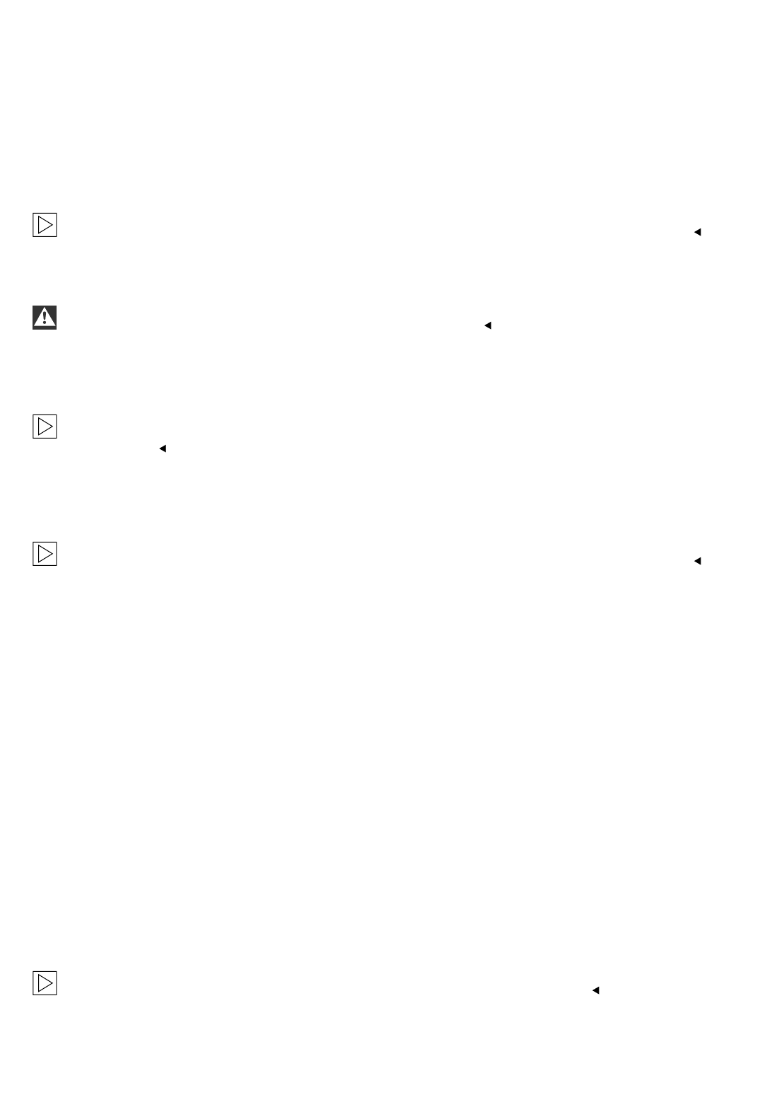
2.8 To remove the manual headlight adjustment control system (ECE cars only)
A
Remove the fresh air grille (1).
Remove the light control (2) with the manual headlight adjustment control system (3) and replace it with the light
control in the parts kit.
To install the parts proceed in reverse order.
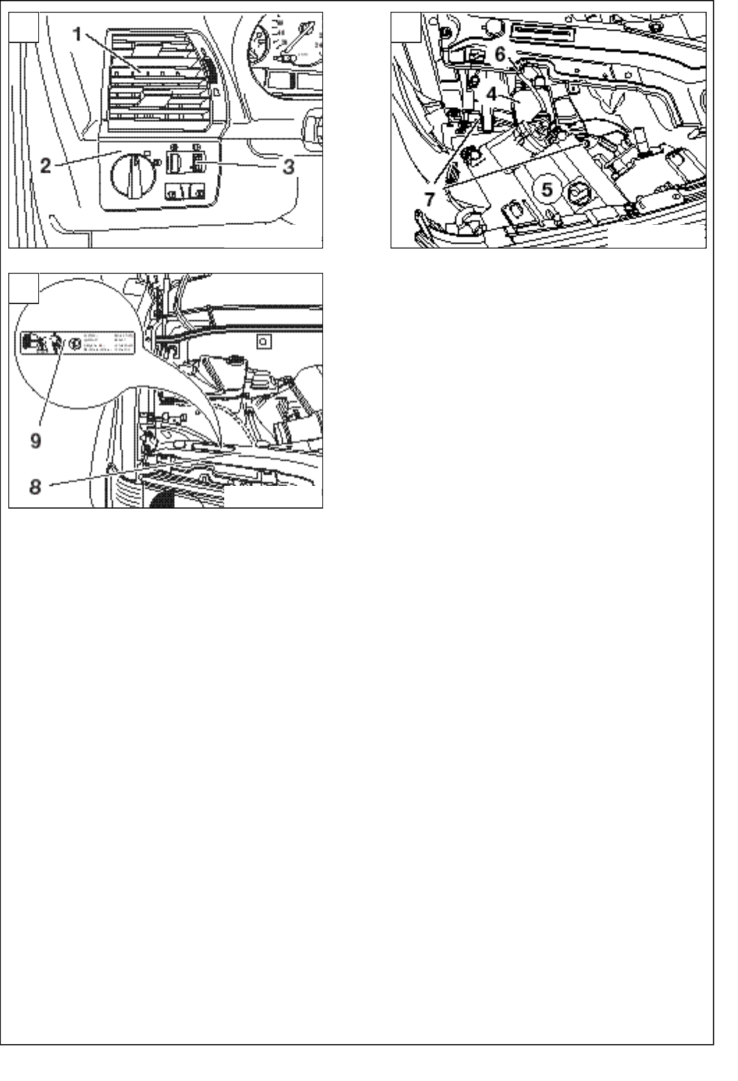
2.9 To install the xenon headlights
The procedure is shown for the right-hand side of the car, proceed accordingly on the left-hand side.
B
Take the holder with the integral control module (4) off the xenon headlight (5).
The control module (4) is connected to the headlight by a cable (6).
Position the holder and integral control module (4) in the car with the screws (7), position. Align and secure the
xenon headlight (5).
Connect all the plug connectors.
On US cars also connect the 4-pin plugs X1034 and X1035 (branches Hand Kon the xenon wiring harness)
to the servo motors.
2.10 To affix the warning sticker
C
The procedure is shown for the right-hand side of the car, proceed accordingly on the left-hand side.
Clean the cross traverse (8) and affix the warning sticker (9).
2.11 To assemble the car
Assemble the car by replacing all the parts you removed, but in reverse order.
2.12 Coding
This retrofit system is coding-relevant.
The coding is required to ensure that the retrofit system is fully functional and to rule out the possibility of
malfunctions and faults when it works in conjunction with other electrical systems in the car.
In addition the retrofit system is saved in the central code of the IKE (integrated combination electronics)/
instrument combination.
The coding work is to be completed using the DIS/MoDIC and is performed automatically in the "Retrofit" path
using the latest coding program.
The procedure is user-guided. Refer to the text instructions as you go through the various stages.
Print out the error memory and conduct a function test.
2.13 Function test
When you switch on the dipped headlights, the headlights must adjust automatically.
Check the function of the automatic headlight adjustment control system by loading the front and rear of the car.
EN/2-133

2.14 To adjust the xenon headlights
Check the standard adjustment of the headlights as described by the manufacturer and adjust it if necessary.
2-134/EN
2-147
B
C
F 53 0086 EVA
F 53 0087 EVA
A
F 53 0085 EVA

3. Circuit diagram
3.1 Circuit diagram (for ECE cars only).......................................................................................... 3-3
3.2 Circuit diagram (for US cars only)............................................................................................3-12
3-1
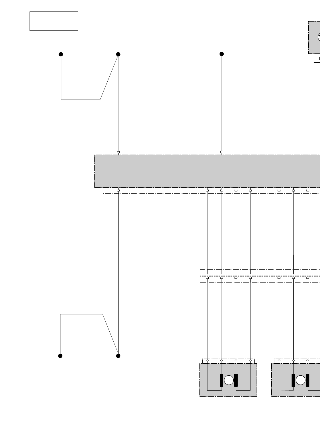
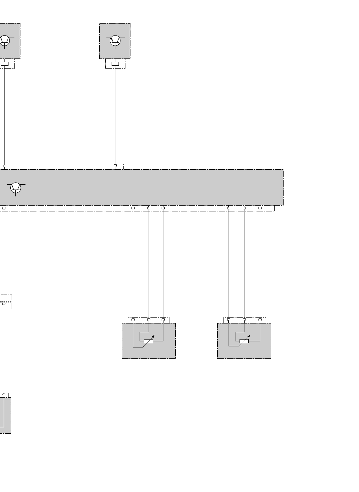
3.1 Circuit diagram (for ECE cars only)
Fold out folded page 3-9.
A3 Light module
A52 ABS/DSC control module
A53 Headlight adjustment control system (LWR) control module
B42 Load sensor at the rear right
B64 Load/level sensor at the front right
M80 Headlight servo motor, left
M81 Headlight servo motor, right
X1B* Black 10-pin plug
X1S* Black 10-pin plug
X596 Terminal 31 connector
X991 26-pin plug, Bordeaux
X1034 4-pin plug, natural (left headlight)
X1035 4-pin plug, natural (right headlight)
X1170 42-pin plug, natural (ABS/ASC control module)
X1451 6-pin plug, black (level sensor, rear right)
X1608* Terminal 31 connector
X10116 K-bus connector
X10117 54-pin plug, black (light module)
X10275 6-pin plug, black (level sensor, front right)
X10466* K-bus connector
The components marked "*" only refer to this circuit diagram, all other components refer to the BMW dealer
organisation circuit diagram.
The cables marked ”#” are in the vehicle wiring harness and are not supplied with the xenon light retrofit kit.
Cable colours
BL = blue
BR = brown
GE = yellow
GN = green
GR = grey
RT = red
SW = black
WS = white
EN/3-3
M M
A3
VB K-BUS
54
X10466*
K-BUS
14 21
x0,35
WSRTGE x0,5
BLRT
KL 54 (Pin 25)
X10117
X596
A53
X1034
Q21
Q21
1
1
3
Q21
326
Q2131E<IV
x0,5
BLRT
x0,5
BRSW
x0,5
BLRT
VB31 X1608*
VB31
214
Q22 Q11 Q12
Q22 Q11 Q12
Q22 Q11 Q12
2
2
3
3
4
4
4
Q22 1
Q11 2
Q12
x0,5
GEBR
x0,5
GERT
x0,5
BLBR
x0,5
GEBR
x0,5
GERT
x0,5
BLBR
1089
3
Q21 4
Q22 1
Q11
Q21 Q22 Q11
Q21 Q22 Q11
Q21 Q22 Q11
7
7
8
8
9
9
x0,5
GESW
x0,5
BLBR
x0,5
BLSW
x0,5
GESW
x0,5
BLBR
x0,5
BLSW
M80
LTG. VERDLTG. VERDRILLTLTG. VERDRILLTLTG. VERDRILLT
LTG. VERDLTG. VERDRILLTLTG. VERDRILLTLTG. VERDRILLT
x0,5
BRSW
VB K-BUS
X10116
x0,35
WSRTGE
#### ###
ECE
A52
X10117
27
LWR
X1170
18
DFAVR
DFAVR
LWR
13 24
x0,5
GERT x0,35
GEWS
X991
11
2
Q12
Q12
Q12
Q12
X1035
10
10
x0,5
GEBRW
x0,5
GEBRW
X1S*
X1B* 623 623
X1451 X10275
B42 B64
20 7 22 16 5 18 X991
xx0,5
GRGN 0,5
GRWSx0,5
GRBR x0,5
SWGN x0,5
SWWS x0,5
SWGR
HSSH HSGH HSPH
HSSH HSGH HSPH
HSSV HSGV HSPV
HSSV HSGV HSPV
M81
F 53 0088 EVA
DRILLT
DRILLT
#
3-9
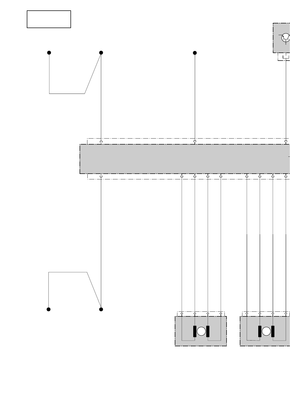
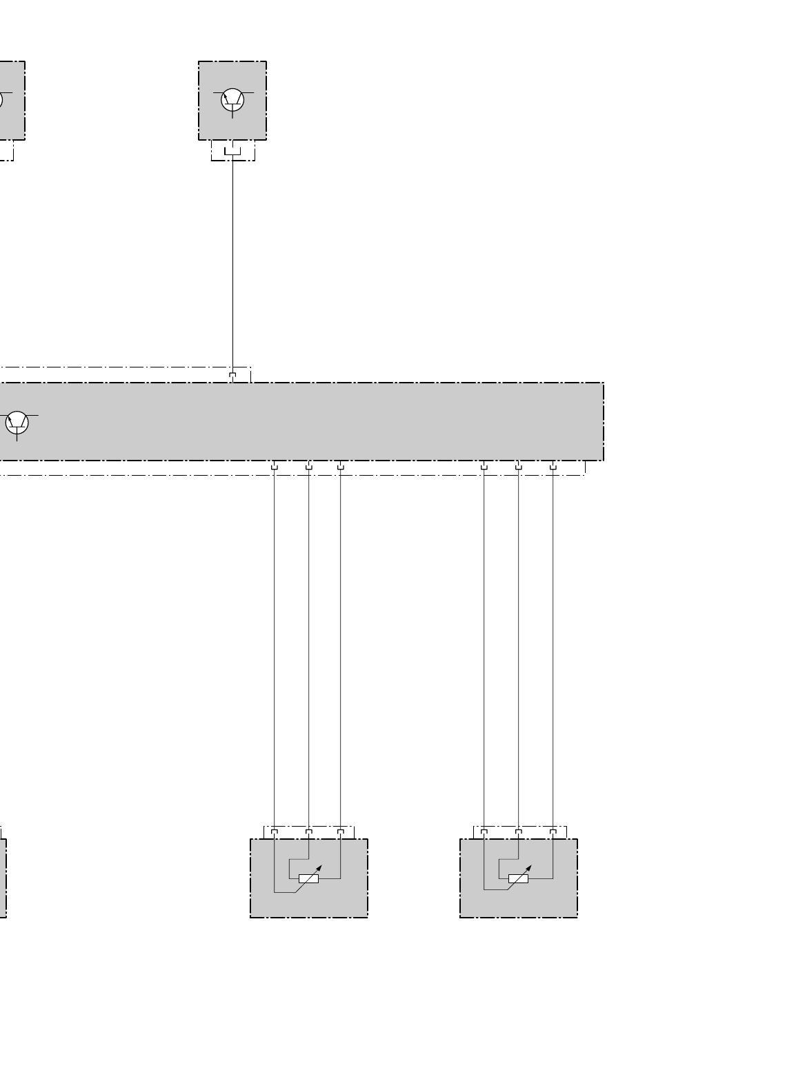
3.2 Circuit diagram (for US cars only)
Fold out folded page 3-19.
A3 Light module
A52 ABS/DSC control module
A53 Headlight adjustment control system (LWR) control module
B42 Load sensor at the rear right
B64 Load/level sensor at the front right
M80 Headlight servo motor, left
M81 Headlight servo motor, right
X596 Terminal 31 connector
X991 26-pin plug, Bordeaux
X1034 4-pin plug, natural (left headlight)
X1035 4-pin plug, natural (right headlight)
X1170 42-pin plug, natural (ABS/ASC control module)
X1451 6-pin plug, black (level sensor, rear right)
X1608* Terminal 31 connector
X10116 K-bus connector
X10117 54-pin plug, black (light module)
X10275 6-pin plug, black (level sensor, front right)
X10466* K-bus connector
The components marked "*" only refer to this circuit diagram, all other components refer to the BMW dealer
organisation circuit diagram.
Cable colours
BL = blue
BR = brown
GE = yellow
GN = green
GR = grey
RT = red
SW = black
WS = white
3-12/EN
M M
A3
LWR
VB K-BUS
LWR
54
X10466*
K-BUS
13
14 21
x0,35
WSRTGE x0,35
BLRT x0,5
GE
KL 54 (Pin 25)
X10117
X596
A53
X1034 3
Q21
326
Q21
31E<IV
x0,5
BRSW
VB31 X1608*
VB31
214
Q22 Q11 Q12
4
Q22 1
Q11 2
Q12
111089
3
Q21 4
Q22 1
Q11 2
Q1
Q21 Q22 Q11 Q12
M80
x0,5
BLRT x0,5
GEBR
x0,5
GERT
x0,5
BLBR x0,5
GE
x0,5
GESW
x0,5
BLBR
x0,5
BLSW
LTG. VERDRILLLTG. VERDRILLTLTG. VERDRILLTLTG. VERDRILLT
x0,5
BRSW
VB K-BUS
X10116
x0,35
WSRTGE
USA
X10117
27
3
5
ERT
A52
X1170
18
DFAVR
DFAVR
24
x0,35
GEWS
X991
1
12
X1035 623 623
X1451 X10275
B42 B64
20 7 22 16 5 18 X991
x0,5
GRGN x0,5
GRWSx0,5
GRBR x0,5
SWGN x0,5
SWWS x0,5
SWGR
HSSH HSGH HSPH
HSSH HSGH HSPH
HSSV HSGV HSPV
HSSV HSGV HSPV
M81
F 53 0089 EVA
5
EBR
LLT
3-19
