BOLENS Lawn, Tractor Manual L0904580
User Manual: BOLENS BOLENS Lawn, Tractor Manual BOLENS Lawn, Tractor Owner's Manual, BOLENS Lawn, Tractor installation guides
Open the PDF directly: View PDF ![]() .
.
Page Count: 36
Balenmo
Models
13000
13O01
13002
13003
13004
13005
13OO6
13007
13055
13057
13O67
13O68
8HP28"sidedischarge
8.5HP28"sidedischarge
8.5HP28"sidedischarge(Export)
12.5HP33"mulcher
12.5HP(Australia)
12.5HP36"sidedischarge
12.5HP36"sidedischarge(Export)
12.5HP33"mulcher(Export)
8 HP28"sidedischarge
8.5 HP28"sidedischarge
12.5HP33"mulcher
12.5HP33"mulcher(Export
©1993 GardenWay Inc.
Owner/Operator
Manual
RidingMower
FORM1768445(8/93)
SupersedesFORM1763980Rev.B(10/92)

INTRODUCTION
Thank you for purchasing this Bolens ® riding mower. We feel you now own one of the finest pieces of equipment
available.
This is a safety, operation, and general maintenance manual which does not attempt to cover major repairs.
Bolens ® equipment is carefully designed, engineered and manufactured to give good performance if properly
operated and maintained. Review this manual to familiarize yourself with the unit, its features, and its operation.
All Bolens ® mowers have passed rigid safety standards of the Outdoor Power Equipment Institute and an independent
testing laboratory.
Your Warranty Statement is included, on the back cover of this manual. Please read it carefully. Also please return
the completed postpaid owner registration card which is included with this manual. Proper registration is required for
all warranty claims.
IDENTIFICATION NUMBERS
For prompt servicewhen repairs oradjustments are required,
your authorized Bolens_ dealer must have the identification
numbers of your riding mower. Pleasefill in the identification
numbers in the spaces below for future reference. Your
identification numbers are located under the seat as shown to
the right.
Dateof Purchase:
Mower Serial Number:
Transmission Model/Serial Number:
EngineModel/Serial/Spec. Numbers:
Model/Serial
Number
WARNING TO ALL CALIFORNIA
AND OTHER RIDING MOWER OPERATORS
Under California law, and under the laws of several other states, you are not permitted to operate an internal
combustion engine using hydrocarbon fuels on any forest covered, brush covered, or grass covered land, or on
land covered with grain, hay, or other flammable agricultural crop, without an engine spark arrester in continuous
effective working order.
The engine on your riding mower, like most outdoor power equipment, is an internal combustion engine that burns
gasoline, a hydrocarbon fuel. Therefore, your riding mower must be equipped with a spark arrester muffler in
continuous effective working order. The spark arrester must be attached to the engine exhaust system in such a
manner that flames or heat from the system will not ignite flammable material. Failure of the owner/operator of the
riding mower to comply with this regulation is a misdemeanor under California law, and may also be a violation of
other state and/or federal regulations, laws, ordinances, or codes. Contact your local fire marshal or forest service
for specific information about what regulations apply in your area.
TABLE OF CONTENTS
SAFETY..............................................................i........... 3
ATrACHMENTSAND KITS............................................. 6
SPECIFICATIONS...........................................................6
ASSEMBLY.................................................................... 8
HITCH.......................................................................... 8
COLUMNSUPPORT..................................................... 8
BATTERY...................................................................... 8
SEAT............................................................................ 9
ENGINEOIL.................................................................. 9
SPARKPLUG............................................................... 9
MOWERDECKINSTALLATION.................................... 9-16
CONTROLSAND OPERATIONi....................................... 18
CONTROLS.................................................................. 17
EngineSpeed Lever.................................................... 17
BrakePedal................................................................ 17
Parking Brake............................................................ 17
IgnitionKeyswitch...................................................... 17
Drive Pedal................................................................. 17
Mower BladeDriveLever........................................... 17
Mower HeightAdjustingKnob................................... 17
TransmissionShift Lever........................................... 17
Mower Lift Lever........................................................ 18
OPERATION................................................................. 18
Pre-StartingChecklist................................................ 18
Filling FuelTank......................................................... 19
Starting....................................................................... 19
InterlockSystem Test................................................ 20
Mowing...................................................................... 20
TestingHeightof Cut................................................. 21
GageWheelAdjustment............................................. 21
Stopping .................................................................... 22
Parking....................................................................... 22
MowingTips.............................................................. 22
SpecialPatternEffects............................................... 22
MAINTENANCE.............................................................. 23
TRACTORMAINTENANCE............................................ 23
Engine........................................................................ 23
BrakeAdjustment....................................................... 23
TransmissionDriveBeltAdjustment.......................... 23
Battery........................................................................ 24
MOWERDECKMAINTENANCE.................................... 25
Mower DriveBeltReplacement.................................. 25
Mower DriveBeltAdjustment..................................... 27
Mower DeckBrakeAdjustment.................................. 28
BladeMaintenance..................................................... 29
STORAGE..................................................................... 31
MAINTENANCECHART.................................................. 32
TROUBLESHOOTINGCHART......................................... 32
WIRING DIAGRAM......................................................... 35
WARRANTY...................................................... BACKCOVER
SAFETY
IMPORTANT!
Safe Operation Practices for Riding Mowers
This is asafety alert symbol. It is used in
this Manual and on riding mower decals to
alert you to potential hazards.
Wheneveryou see this symbol, read and obeythe safety
messagethat follows it. Failureto obey the safetymessage
couldresultinpersonalinjuryorpropertydamage.
TRAINING
PREVENTINGACCIDENTSIS THE
RESPONSIBILITYOF EVERYEQUIPMENT
OPERATOR.THE OPERATORIS
RESPONSIBLEFORACCIDENTSOR
HAZARDSOCCURRINGTO OTHER
PEOPLEORTHEIRPROPERTY. THE
FOLLOWINGGENERALSAFETY
PRECAUTIONSMUST BEFULLY
UNDERSTOODAND FOLLOWEDWHEN
OPERATINGYOURRIDING MOWER.
REVIEWTHEM FREQUENTLYAND NEVER
TAKECHANCES.BECAREFULBEFORE,
DURINGAND IMMEDIATELYAFTERUSE
OFANYPOWEREDEQUIPMENT.
ACCIDENTSCANBE PREVENTED.
1. Beforeoperatingthe unit: 4.
a. Readthis owner/operator manual,the
separateengineowner'smanual,and 5.
any other literature you may have
received.
b. Bethoroughly familiar with the
controls and proper use of theunit.
c. Readall literature furnished with any
attachments used on the unit.
d. Knowhow to stop the unit and
disengage its controls quickly in case
of an emergency.
2. NEVERallow children to operatethe
unit. Localregulations may restrict the
age of the operator.
3. Do not allow adults to operatethe unit
withoutproper instruction.
Neverallow irresponsible adults to
operatethe unit.
Keepthearea of operation clear of all
persons (particularly small children)
and pets.
GENERAL OPERATION
,Thoroughlyinspect the areawherethe
unit will be used:
a. Removeall stones, sticks, wires,
bones, and other foreignobjects.
Tall grass can hide obstacles.
b. Inspect the areafor holes, ruts, or
bumps. Uneventerrain could
overturn the unit.
2. Wear proper clothing before operating
the unit:

SAFETY (Cont.)
a. Donot operate the unit when
barefoot or wearing open sandals.
Always wear substantial footwear.
b. Always wear long trousers.
c. Do not wear loose-fitting clothing or
jewelry that could get caught in
moving parts.
d. Beaware that vines, branches, etc.,
('ansnag loose-fitting clothing or
jewelry.
3. Before attempting to start the engine:
a. Apply the parking brake.
b. Disengagethe mower bladedrive.
c. Shift into neutral.
.
.
.
Mow only in daylight or in good
artificial light.
Neveroperate the unit in wet grass--
reduced traction could cause sliding.
Always maintain proper traction. Keep
a firm grip on the steering wheel.
Neverattempt to stabilize the unit by
putting your foot on the ground.
Use carewhen pulling loads or using
heavyequipment:
a. Use only approved drawbar hitch
points.
b. Limit loads to those you can safely
control.
c. Do not turn sharply. Slow down
before turning. Usecare when
backing up.
d. Use optional counterweight(s) or
wheel weights when using
attachments which affect the balance
of the unit.
.
.
Neverattempt to defeat the purpose of
guards or other safety devices installed
on the unit. Never operate the unit
with defective guards or shields, or
without safety devices in place.
Before use,always visually inspect the
mower blade(s) and bladebolts and
replaceif they are worn or damaged.
Replaceworn or damaged blades and
bolts in sets to maintain proper
balance. Torque the bladebolts to the
correct troque values indicatedin this
manual.
9. If the unit has a two bladedeck,usecare
whenrotatingonebladebecausethis can
causethe other bladeto rotate.
10. Useextra carewhen loadingor
unloading the unit into a trailer or
truck.
11. Beforeattempting to start the engine:
a. Apply the parking brake.
b. Disengagethe mower bladedrive.
c. Shift into neutral.
12. Do not changethe enginegovernor
settingsor over-speedthe engine.
Operatingan engineat excessivespeed
mayincreasethe hazardof personal
injury.
13.Do not put hands or feet near or under
rotatingparts. Keepclearof the
dischargeopeningat alltimes. Beaware
of the mower dischargedirectionanddo
not point it at anyone. Do not operatethe
unit without eitherthe entireoptional
baggingattachmentor thedischarge
chutein place.
14.Watch for traffic when operatingnear,or
when crossingroadways.
15. Disengagethe mower blade drive and
wait for the mower blades to come to a
stop when crossing gravel drives,
walks, or roads.
16.Nter striking a foreign object:
a. Disengagethe mower blade drive.
b. Stop the engine.
c. Wait for all moving parts to come to
a complete stop.
d. Removethe wire from the spark plug.
e. Keepthe wire awayfrom the plug to
preventaccidental starting.
f. Thoroughly inspect the unit for any
damage,and repairthe damage
before re-starting and operating the
unit.
17. If the unit should start to vibrate
abnormally, stop the engineand check
immediatelyfor the cause; Vibration is
generallya warning of trouble.
18. Before cleaning the mower deck
housing, before cleaning the unit and
before makingany repairs or
inspections:
a. Disengagethe mower blade drive.
b. Stop the engine.
C.Wait for all moving parts to come to
a complete stop.
d. Removethe wire from the spark plug.
e. Keepthe wire away from the plug to
preventaccidental starting.
19.Stop the engine wheneveryou leave
the unit.
20. Do not run the engine indoors.
Exhaust gasescontain carbon
monoxide, a deadly gas that is
odorless and colorless. Always run the
engine outdoors and make sure there
is adequateventilation.
21.Stop the blade (move the mower
blade drive lever to its disengaged
position) wheneveryou are
approached by any child, inattentive
person, or pet.
22. Disengagethe mower blade drive when
you are not mowing.
23. Do not touch engine partswhich may
be hot from operation. Allow the
engineto cool before inspecting,
cleaning,or repairing the unit.
24. Do not operate the unit while under the
influence of alcohol or drugs.
25.Use low throttle settings when
engagingthe drive pedal, especially in
high gears.
26. Neverattempt to carry any passengers
on the unit. Theycould fall off and be
seriously injured, or they could
interfere with the safeoperation of the
unit.
27. Useextra care when approaching
blind corners, shrubs, trees, and any
other object that may obscure vision.
28. When using any attachments, never
direct the discharge of materialtoward
bystanders.
29.There is a safety interlock switch which
should shut down the engine within a
few seconds after the operator leaves
the seat. If this switch fails to operate,
get the unit serviced immediately by an
authorized Bolens® dealer. Severe
injury could result from not following
this instruction.
30.Never leavea running machine
unattended. Always disengagethe
mower bladedrive, set the parking
brake, stop the engine and removethe
keys before dismounting.

SLOPE OPERATION
1. MOWup anddownthe face of a
slope--Never across.
2. Keepall movement ona slope slow
and gradual. Do not makesudden
changes in speed or direction. Do not
turn onslopesunless necessary,and
then, turn slowly and gradually
downhill, if possible. Useslow speed.
Choosea low gearso you will not have
to stop or shift while on the slope.
,
;
5.
Do notstop or start suddenly on a
slope. If the tires loose traction,
disengagethe mower bladedrive and
proceed slowly straight down the
slope.
Do not mow steep slopes.
Do not mow near drop-offs, ditches, or
embankments. If a wheel goes over
the edge, or if the edge caves in, the
unit could overturn.
1
SERVICE
1, Handlegasoline with care -- it is
highly flammable:
a. Usean approved gasoline container.
b. Neverremovethe fuel cap of, or add
gasoline to, a running or hot engine
orto an engine that has not been
allowedto cool for severalminutes
after running.
Neverstore the unit or fuel container
inside where there is an openflame,
such as in awater heater.
c. Keepsmoking materials,sparks,and
flame awayfrom the gas tank and the
fuel container.
2. Checkthe fuel before starting the
engine:
a. Do not fill the gasoline tank indoors,
when the engineis running or until
the engine has beenallowed to cool
for severalminutes after operating.
b. Cleanoff any spilled gasoline before
starting the engine.
Useextra carewhile using the optional
model 6028 or 6036 grass collection 3.
attachments. Thesecan changethe 4.
stability of the unit. Usewheel- and/or
counter-weights when using these
attachments. Do not use them on
steepslopes. 5.
CHILDREN
1. Tragic accidents can occur if the
operator is not alert to the presenceof
children. Children are often attracted
to the unit and the mowing activity.
Neverassume that children will remain
where you last saw them. Keep
children out of the mowing area. Keep
them under the watchful eye of an
adult other than the person operating
the unit.
Bealert and turn unit off if children
enter the area.
2. Before backing up:
a. Look behind you and on the ground
immediately behind the unit before
backing up and while running in
reverse.
b. Be sure to look down and behind you
for small children. A large
percentageof accidents involving
children occur while backing up.
c. Disengagethe mower blade drive
before backing up.
Replaceany worn or damaged parts.
Checkthe bladeand the engine
mounting bolts at frequent intervals for
proper tightness.
Neverstore the unit with gasoline in
the fuel tank inside a building where
gasolinefumes could reach anopen
flame or spark.
6. When storing gasoline:
a. Store gasoline in a cool, well-
ventilated area,safely awayfrom any
spark- or flame-producing
equipment.
b. Store gasoline in an approved
container, safely out of the reachof
children.
7. If the fuel tank has to be drained, drain
it outdoors.
,
,
Allow the engineto cool before storing
this unit in any enclosure.
To reduce fire hazard,keepthe engine
free of grass, leaves,or excessive
grease.
18,Checkthe (optional)grass catching
bag. Under normal use,the bag's
material is subject to deterioration and
wear. It should be checkedfrequently
and replacedwhen necessary. Use
onlya genuine Bolens®replacement
bag.
SAFETY (Cont.)
11. Useonly original-equipment
replacement parts. Parts
manufactured by others could present
safety hazardseven thoughtheymayfit
on theunit.
12. Beforeinspecting, cleaning, adjusting,
or repairing the unit:
a. Disengagethe mower bladedrive.
b. Stop the engine.
c. Wait for all moving parts to cometo
a complete stoP.
d. Removethe wire from the spark plug.
e. Keepthe wire away from the plug to
preventaccidental starting.
f. Allow the engine to cool.
13.Keepallnuts, bolts, and screws tight to
besure the unit is in safeworking
condition.
14. Replacea wornorfaulty muffler.
15. Do not allow children to be nearyou
when you are serviceing this unit.
16. Removethe battery, drain the fuel tank
and drain the engine oil if it becomes
necessaryto tip the unit up on its end
or on its side. Fluidscan leakfrom the
unit if it is tipped over.
17;Chock the wheels (place blocks of
wood on both sidesof the wheels)
wheneveryou haveto performany
maintenancethat requires the parking
brake to beoff.
18.Mower blades aresharp and can cut.
Wrap the blade(s) or wear gloves, and
use extra caution when servicing them.
19.Checkbrake operation frequently.
Adjust and service as required (See
page23).
DECALS
For your personal safety andthe safety of
others,safety messagedecals have been
placed on your riding mower. Makesure
thesedecals are in place, cleanand legible
at all times. Refer to the separateparts
catalogfor decal locations, part numbers,
and ordering instructions.
ATTACHMENTS AND KiTS
Below is a list of attachments and kits that are available for your unit, The information is the most current at the time
this manual was printed. Check with your nearest Bolens ® dealer for up-to-date information.
Kit Number Description
6O28
6036
6957
6958
Power packer Bagging Attachment for 28" decks
Power packer Bagging Attachment for 36"" decks
Storage Stand (Stands unit up on rear end for storage/maintenance,)
Wheel Weights, 701bs. (pair)
SPECIFICATIONS
Bolens ® reserves the right to make changes in specifications shown herein, add improvements or 6iscontint_e the
manufactured product at any time without notice or obligation.
Models 13000, 13001,13002, 13055 & 13057
Engine...........................Models 13000 & 13055--Briggs& Stratton
Mode_195707
Verticalshaft8 He
(seeenginemanualforfurtherdetails)
Models13001, 13002 & 13057--Briggs&
Stratton
Model196707
Verticalshaft8.5HP
(seeenginemanualfor furtherdetails)
FuelCapacity.................1U,S,Gal,(3.7 Liters)
ElectricalSystem..........12v./160cca
Speed............................HighGear:4.0 MPH(6.5 Km/Hr).
LowGear:1.2MPH(1,9 Km/Hr)
Reverse:1.5 MPH(2.4 Km/Hr)
Tires..............................Models13000 & 13055
Front:4.10/3.50x 8
Rear:4,80/4,00x 8
Models13001, 13002 & 13057
Front:11.00x4.00x 5.00
Rear:16x 6.50x 8
TurningRadius.............23"(58,4cm)
Height...........................38.5"(98cm)
Width(at reartires) ......32"(81cm)
CuttingWidth................28"(71cm), sidedischargemowerdeck
No.of Blades................1
Cuttingheightrange.....1"to 3"(2,5 cmto 7.5 cm)
Weight..........................340Ibs(154Kilos)
Modets 13003,13007, 13067 & 13068
Engine...........................Bfiggs&Stratton
Model286707
Verticalshaft12,5HP
(seeenginemanualfor furtherdetails)
FuelCapacity.................1U,S.Gal.(3.7 Liters)
ElectricalSystem..........12v./160cca
Speed............................HighGear:4.0M£H(6.5Krn/Hr)
LowGear:1.2MPH(1.9 Km/Hr)
Reverse:1,5MPH(2.4 Km/Hr)
Tires..............................Front:11.00x 4.00x 5.00
Rear:16x 6.50x 8.00
TurningRadius.............23"(58.4cm)
Height...........................38.5"(98cm)
Width(atreartires)......32"(81cm)
CuttingWidth................33"(84cm_.mu{_h{n9m_'_ _c_,
No.of Blades................2
Cuttingheightrange.....1"to 3"(2,5 cmto 7,5 cm)
Weight..........................350Ibs(159Kilos)
Model 13004
Engine............................Briggs& Stratton
Model286707
Verticalshaft12.5HP
(seeenginemanualfor _urtherdetails)
FuelCapacity.................1 U,S,Ga),(3,7 Liters)
ElectricalSystem..........12v./160cca
Speed............................HighGear:4,0 MPR(6.5Km/Hr)
LowGear:12MPH(1,9 Km/Hr)
Reverse:1.5MPH(2.4 Km/Hr)
Tires..............................Front:11,00x 4,00x5.00
Rear:16x 6,50x 8.00
TurningRadius.............23"(58.4cm)
Height...........................38.5"(98cm)
Width(atreartires)......32"(81cm)
CuttingWidth(s)...........28"(71cm),
sidedischarge;33"(84cm),mulchingmower;
36"(91cm)sidedischarge
No.ofBlades................1 (28"),2 (33"& 36")
Cuttingheightrange.....1"to 3.25"(2.5cmto 8.3 cm)
Weight..........................340Ibs(154Kilos)to 360Ibs [163_,ilos)
Models 13005 & 13006
Engine...........................Briggs&Stratton
Model286707
Verticalshaft12.5HP
(seeenginemanualfor furtherdetails)
6
SPECIFICATIONS (Cont.)
FuelCapacity.................1U.S.Gal.(3.7Liters)
ElectricalSystem..........12v./160cca
Speed............................HighGear:4°0 MPH(6.5 Km/Hr)
LowGear:1.2MPH(1.9Km/Hr)
Reverse:1.5 MPH(2.4Km/Hr)
Tires..............................Front:11x 5.00x5.00
Rear:16x 6.50x 8
TurningRadius.............23"(56.4cm)
Height...........................38.5"(98cm)
Width(atreartires)......32"(81cm)
CuttingWidth................36' (91cm),sidedischargemowerdeck
No.ofBlades................2
Cuttingheightrange.....1' to3' (2.5 cmto7.5 cm)
Weight..........................360Ibs(163Kilos)
ASSEMBLY
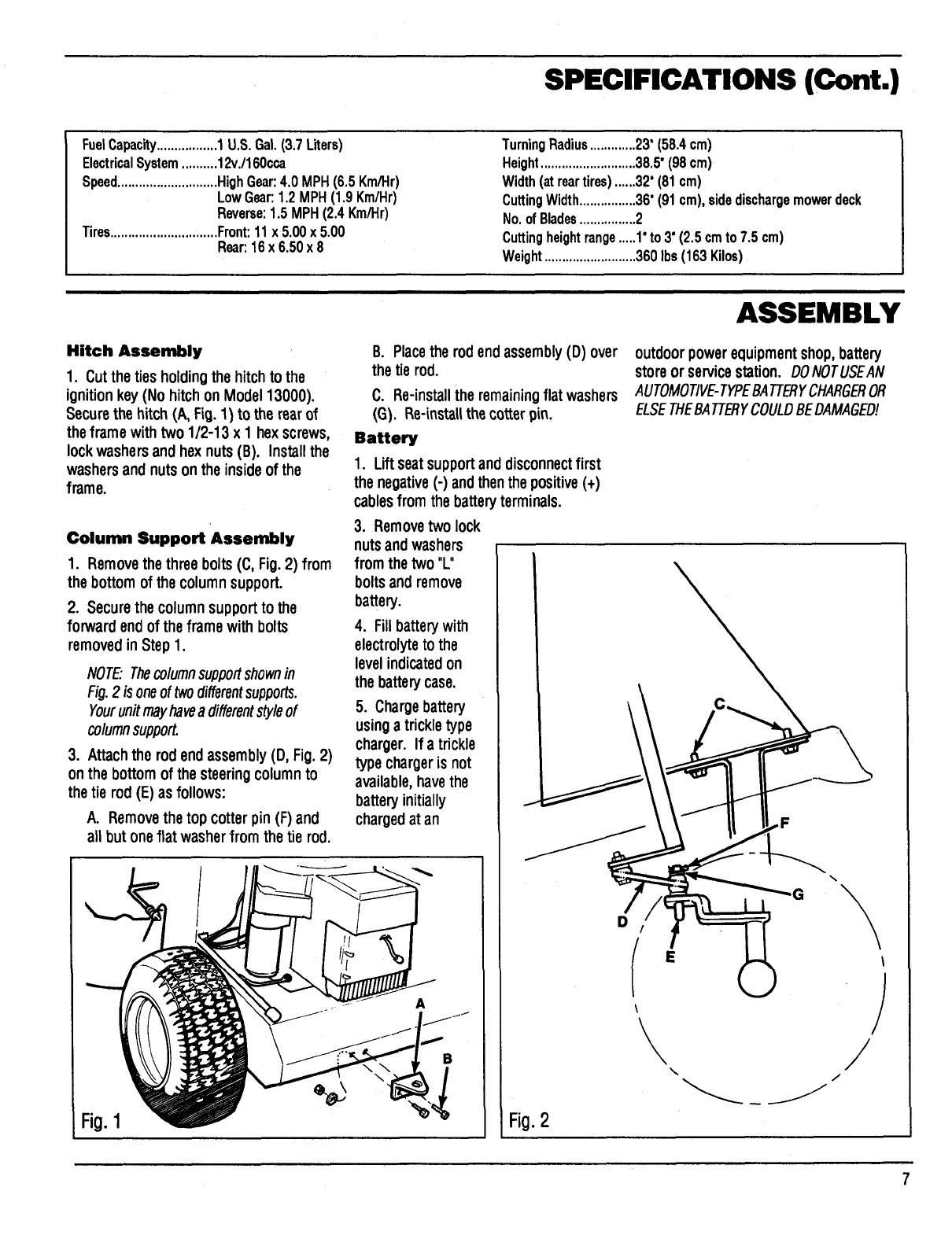
Hitch Assembly
1. Cut the ties holding the hitch to the
ignitionkey(No hitchon Model13000).
Secure the hitch (A, Fig.1) to the rearof
theframe with two 1/2-13 x 1 hex screws,
lockwashersand hex nuts(B). Installthe
washersandnutsonthe insideof the
frame.
Column Support Assembly
1. Removethe threebolts(C, Fig.2) from
the bottomof the columnsupport.
2. Secure the columnsupportto the
forwardendof the frame with bolts
removedin Step 1.
NOTE:Thecolumnsupportshownin
Fig.2 is oneof twodifferentsupports.
Yourun#mayhavea differentstyleof
columnsupport.
3. Attach the rod end assembly (D, Fig. 2)
on the bottom of the steering columnto
the tie rod (E) as follows:
A. Removethe top cotter pin (F) and
all but one flat washer from the tie rod.
B. Placethe rodend assembly(D) over
the tie rod.
C. Re-installthe remaining flat washers
(G). Re-instaUthe cotterpin,
Battery
1. Lift seatsupportanddisconnectfirst
the negative(-) andthenthe positive (+)
cablesfrom the battery terminals.
3. Removetwo lock
nutsandwashers
from the two "L"
boltsandremove
battery.
4. Fillbatterywith
electrolyteto the
levelindicatedon
the batterycase.
5. Chargebattery
usinga trickletype
charger. If a trickle
type chargeris not
available,havethe
batteryinitially
chargedatan
Fio.1
\
B
D
Fio.2
outdoorpowerequipmentshop,battery
storeor servicestation. OONOTUSEAN
AUTOMOTIVE-TYPEBATTERYCHARGEROR
ELSETI-IEBATTERYCOULOBEOAMAGEO!
'G
E
A\\
\
ASSEMBLY (Cont.)
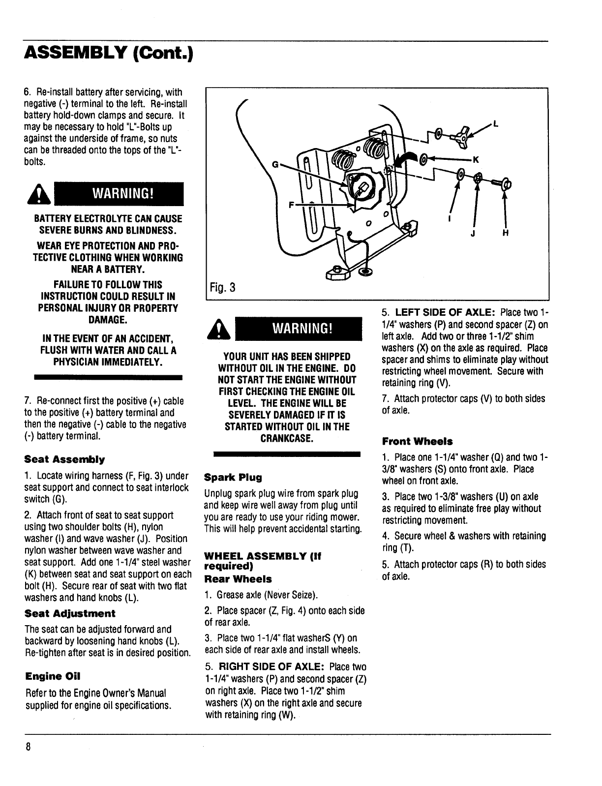
6. Re-install battery after servicing,with
negative (-) terminal to the left. Re-install
battery hold-down clamps and secure. It
may be necessaryto hold "L"-Bolts up
against the underside of frame, so nuts
can bethreaded onto the tops of the "L"-
bolts.
BA'I'rERYELECTROLYTECANCAUSE
SEVEREBURNSAND BLINDNESS.
WEAREYEPROTECTIONAND PRO-
TECTIVECLOTHINGWHENWORKING
NEARA BATTERY.
FAILURETO FOLLOWTHIS
INSTRUCTIONCOULDRESULTIN
PERSONALINJURYOR PROPERTY
DAMAGE.
IN THEEVENTOFAN ACCIDENT,
FLUSHWITH WATERAND CALLA
PHYSICIANIMMEDIATELY.
7. Re-connectfirst the positive(+) cable
to the positive (+) battery terminal and
then the negative (-) cable to the negative
(-) battery terminal.
Seat Assembly
1. Locatewiring harness (F, Fig. 3) under
seat support and connect to seat interlock
switch (G).
2. Attach front of seat to seat support
using two shoulder bolts (H), nylon
washer (I) andwave washer (J). Position
nylon washer between wavewasher and
seatsupport. Add one 1-1/4" steel washer
(K) betweenseat and seat support on each
bolt (H). Secure rearof seatwith two flat
washers and hand knobs (L).
Seat Adjustment
The seat can be adjusted forward and
backward by loosening hand knobs (L).
Re-tighten after seat is in desired position.
Engine Oil
Referto the EngineOwner's Manual
supplied for engine oil specifications.
I
J H
Fig.3
YOURUNIT HASBEENSHIPPED
WITHOUT01LIN THEENGINE. DO
NOTSTARTTHEENGINEWITHOUT
FIRSTCHECKINGTHEENGINE01L
LEVEL. THEENGINEWILL BE
SEVERELYDAMAGEDIF IT IS
STARTEDWITHOUT01LINTHE
CRANKCASE.
Spark Plug
Unplug spark plug wire from spark plug
and keepwire well away from plug until
you are readyto use your riding mower.
This will help prevent accidentalstarting.
WHEEL ASSEMBLY (If
required)
Rear Wheels
1. Greaseaxle (NeverSeize).
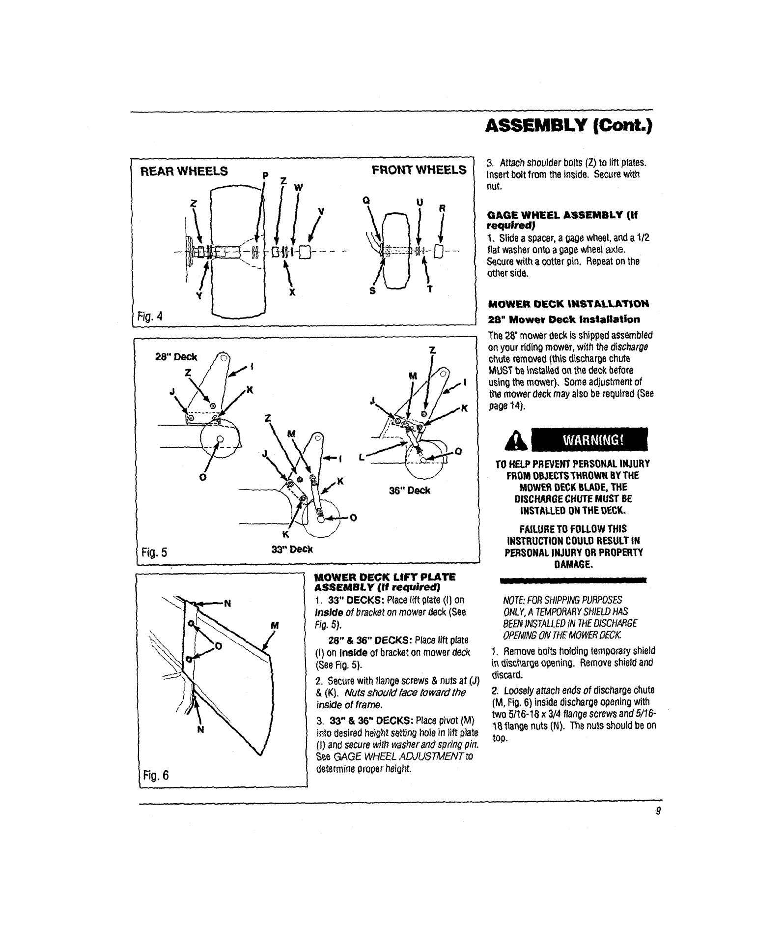
2. Placespacer (Z, Fig.4) onto eachside
of rearaxle.
3. Placetwo 1-1/4" flat washerS(Y) on
each side of rear axleandinstall wheels.
5. RIGHT SIDE OF AXLE: Placetwo
1-1/4"washers(P) and secondspacer(Z)
on rightaxle. Placetwo 1-1/2"shim
washers(X) on the rightaxleand secure
with retainingring(W).
5. LEFT SIDE OF AXLE: Placetwo 1-
1/4"washers(P) and secondspacer(Z) on
leftaxle. Addtwo or three1-1/2" shim
washers(X) onthe axleas required. Place
spacerandshimsto eliminateplay without
restrictingwheelmovement. Securewith
retainingring(V).
7. Attach protector caps (V) to both sides
of axle.
Front Wheels
1. Place one1-1/4" washer(Q) and two 1-
3/8"washers(S) ontofront axle. Place
wheelonfront axle.
3. Placetwo 1-3/8" washers(U) onaxle
as requiredto eliminatefree playwithout
restricting movement.
4. Secure wheel& washerswith retaining
ring(T).
5. Attachprotectorcaps(R) to bothsides
of axle.
ASSEMBLY (Cont.)
REAR WHEELS
Z
*t
Fi0.4
FRONT WHEELS
x
z
%jl
Fig.533"Deck
M
/
/
N
Fi0,6
....
MOWER DEGK LIFT PLATE
ASSEMBLY (if required]
1. 33" DECKS: PlaceI(ft _(ate(() on
Inside of bracket on mower deck(See
FJa.
28" & 36" DECKS: Placelift plate
(I) on inside of bracketonmowerdeck
(SeeFig.5).
2. Secure withflange screws &nuts at (J,_
&(K). Nuts should face toward the
inside of frame.
3. 33" &36" DECKS: Placepivot(M)
intodesired height setf_nghole in lift plate
(1)andsecure wit/7washerand spring pin.
See GAGE WHEEL ADJUSTMENT to
determine properheight.
3. Attach s_ouider bolts(Z) to lift plates.
Insert boltfrom the inside. Secure with
nut.
GAGE WHEEL ASSEMBLY (If
required)
1, Slide a spacer,a gagewheel, anda 1/2
fiat washeronto a9age wheet axle.
Securewith a cotterpin. Repeatonthe
ott_erside,
MOWER DECK IHSIrALLATtOH
28" Mower Deck Installation
The 28" mower deckis shipped assembled
on your riding mower, with the discharge
chuteremoved(thisdischargechute
MUST bs _nstalled on the deckbefore
using the mower), Some adjustmentof
the mower deck may alsobe required(See
page14).
&
TO HELPPREVENTPERSONALINJURY
FROMOBJECTS"THROWNBYTHE
MOWERDECKBLADE,THE
DISCHARGECHUTEMUST BE
INSTALLEDONTHEOECK.
FAILURETO FOLLOWTHIS
INSTRUCTIONCOULDRESULTIN
PERSONALINJURYOR PROPERTY
DAMAGE.
NOTE:FORSHIPPINGPURPOSES
ONLY,ATEMPORARYSHIELDHAS
BEENII_TALLEDtN THEDISCHARGE
OPENINGONTHEMOWER_ECK
1. Remove boltsholding temporary shield
in d{sc_argeopening. Removeshield and
discard.
2. Loosely attachendsof dischargechute
(M, Fig.6) inside discharge opening with
two 5/16-18 x3/4 flange screwsand5116-
1B _angenuts (N). The nutsshould be on
top.
9
ASSEMBLY (Cont.)
3. Looselyattachtop of dischargechute
withtwo 5116-18x 3/4 carriageboltsand
two 5116-18flange nuts(0). Thenuts
shouldbe to the outside.
4. Tightenallfour nutsand boltsinstalled
inSteps 2 and 3.
33" & 36" Inch Mower Deck
Installation
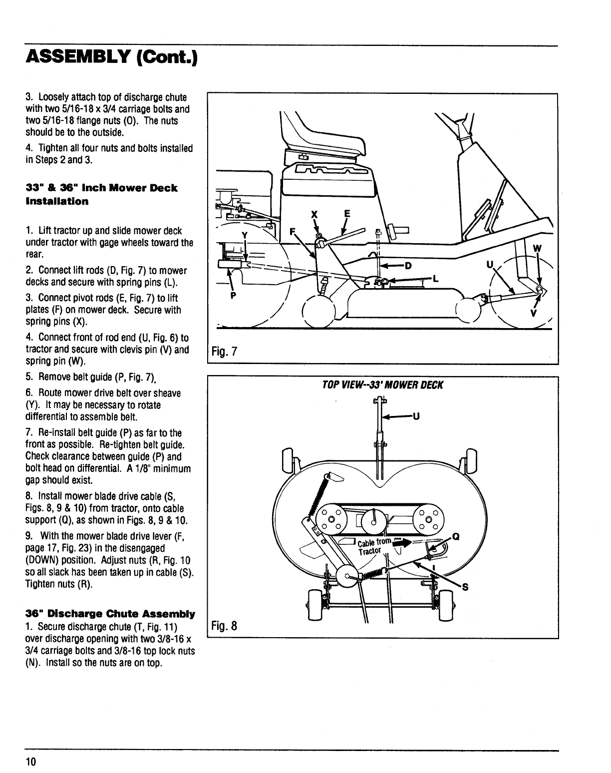
1. Lifttractor upandslide mowerdeck
undertractorwithgagewheelstowardthe
rear.
2. Connect lift rods (D, Fig.7) to mower
decksandsecurewithspringpins (L).
3. Connect pivot rods(E, Fig.7) to lift
plates (F) on mowerdeck. Secure with
springpins (X).
4. Connectfront of rodend (U, Fig.6) to
tractorandsecurewith clevispin (V) and
springpin (W).
5. Removebeltguide(P, Fig.7).
6. Routemowerdrivebeltoversheave
(Y). It maybe necessaryto rotate
differentialto assemblebelt.
7. Re-installbelt guide (P) as farto the
front as possible. Re-tightenbeltguide.
Checkclearancebetweenguide(P) and
bolt headon differential.A 1/8" minimum
gapshouldexist.
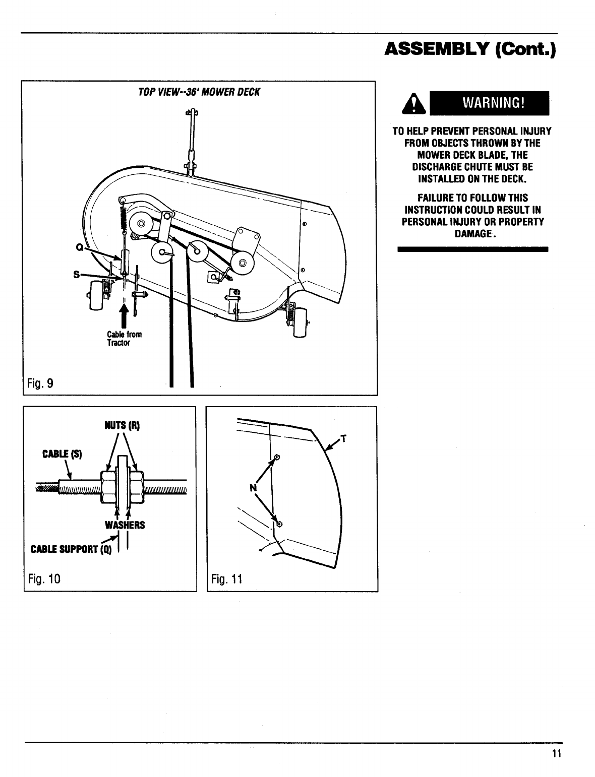
8. Installmowerbladedrive cable(S,
Figs.8, 9 & 10) from tractor,ontocable
support(0), as shownin Figs.8, 9 & 10.
9. With the mower bladedrive lever (F,
page17, Fig.23) inthe disengaged
(DOWN) position. Adjustnuts(R, Fig.10
so all slackhas beentaken upin cable(S).
Tightennuts(R).
36" Discharge Chute Assembly
1. Securedischargechute(T, Fig.11)
overdischargeopeningwithtwo 3/8-16 x
3/4 carriageboltsand3/8-16 toplocknuts
(N). Installso the nutsare on top.
P
Fig.7
Fig.8
(
TOPVIEW--33' MOWERDECK
u
V
10
ASSEMBLY (Cont.)
Fig.9
Cablefrom
Tractor
TOPVIEW--36' MOWERDECK
TO HELPPREVENTPERSONALINJURY
FROMOBJECTSTHROWNBYTHE
MOWERDECKBLADE,THE
DISCHARGECHUTEMUST BE
INSTALLEDONTHE DECK.
FAILURETO FOLLOWTHIS
INSTRUCTIONCOULDRESULTIN
PERSONALINJURYORPROPERTY
DAMAGE.
CaLE(S)
NUTS(R)
WASHERS
CABLJESUPPORT(Q_)I
Fig.10
N
Fig.11
11
ASSEMBLY (Cont.)
RIDER PREPARATION FOR
DIFFERENT SIZED DECKS
28"and36"decksrequirea differentset-
up ofthe ridingmowerthanthe 33" deck.
Set-upfor the twoconfigurationsis
describedbelow.
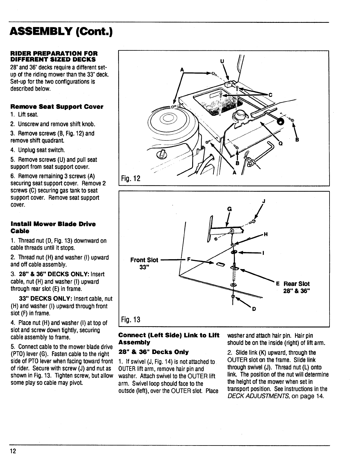
Remove Seat Support Cover
1. Liftseat.
2. Unscrewand removeshift knob.
3. Removescrews(B, Fig.12) and
removeshiftquadrant.
4. Unplugseatswitch.
5. Removescrews(U) andpull seat
supportfrom seatsupportcover.
6. Removeremaining3 screws(A)
securingseatsupportcover. Remove2
screws(C) securinggas tankto seat
supportcover. Removeseatsupport
cover.
Install Mower Blade Drive
Cable
1. Threadnut (D, Fig. 13) downwardon
cablethreads until it stops.
2. Threadnut (H) andwasher(I) upward
and off cableassembly.
3. 28" & 36" DECKS ONLY: Insert
cable,nut(H) andwasher(I) upward
throughrearslot(E) in frame.
33" DECKS ONLY: Insert cable,nut
(H) andwasher(I) upwardthroughfront
slot(F) inframe.
4. Placenut (H) andwasher(I) at top of
slotandscrewdowntightly,securing
cableassemblyto frame.
5. Connect cableto the mowerbladedrive
(PT0) lever(G). Fastencableto the right
sideof PTOleverwhenfacing towardfront
of rider. Securewith screw(J) andnutas
shownin Fig.13. Tightenscrew,but allow
someplay so cablemay pivot.
U
A
C
B
Fig.12
Front Slot
33"
/
J
°/
Fig.13
D
E Rear Slot
281'& 36"
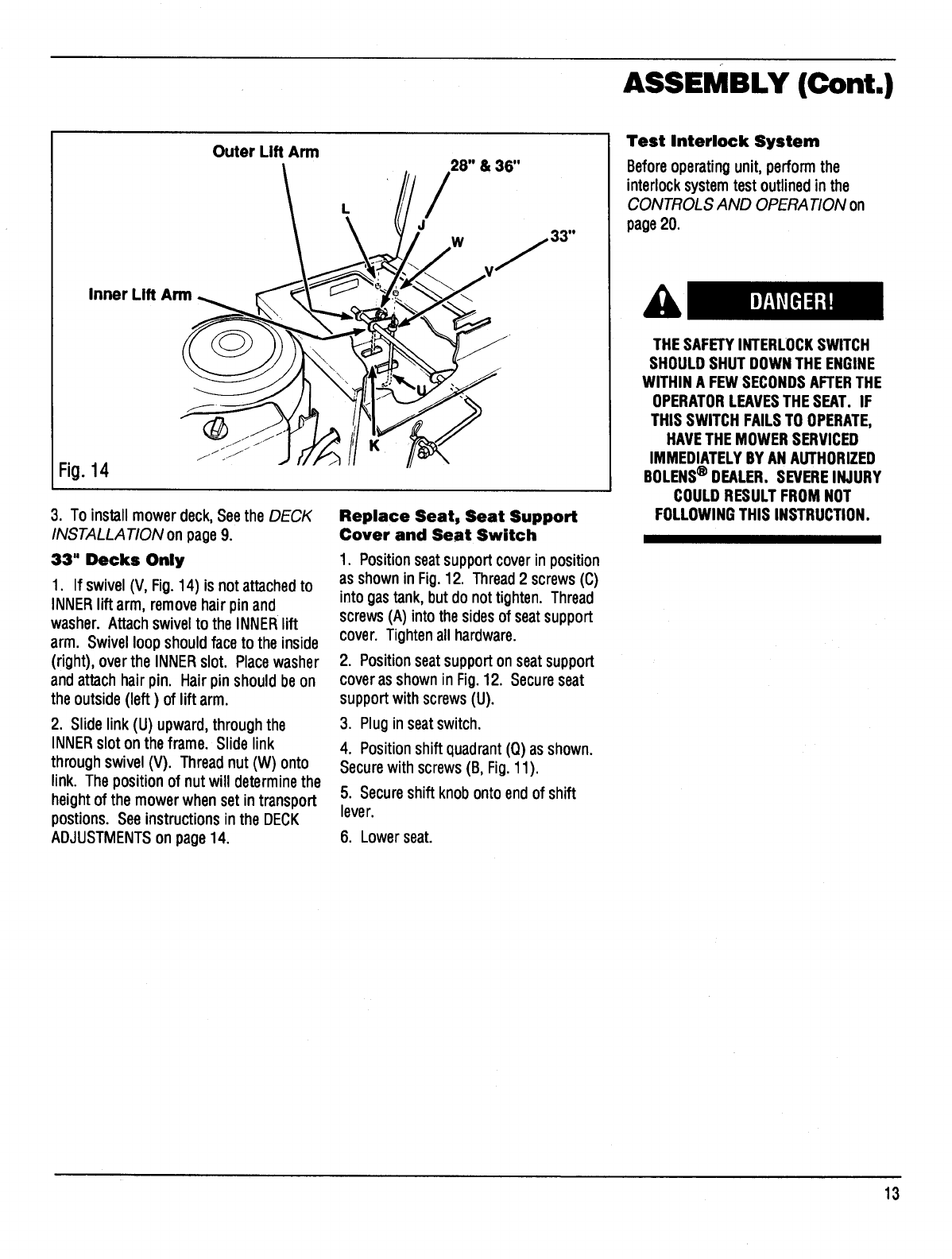
Connect (Left Side) Link to Lift
Assembly
28" & 36" Decks Only
1. If swivel(J, Fig.14) is notattachedto
OUTERliftarm, removehairpinand
washer. Attachswivelto the OUTER lift
arm. Swivelloopshouldfaceto the
outsde(left), overthe OUTER slot. Place
washer andattachhair pin. Hairpin
shouldbe on the inside(right)of lift arm.
2. Slidelink (K) upward,through the
OUTER sloton theframe. Slidelink
throughswivel(J). Threadnut(L) onto
link. The position of the nutwill determine
the heightof the mowerwhenset in
transportposition. Seeinstructionsin the
DECK ADJUSTMENTS, on page 14.
12
ASSEMBLY (Cont.)
Outer Lift Arm
Inner Lift Arm_
Fi0.14
/28" & 36"
J W /33"
3. To install mower deck, Seethe DECK
INSTALLATION onpage9.
33" Decks Only
1. If swivel(V, Fig.14) is not attachedto
INNERlift arm, removehair pin and
washer. Attach swivel to the INNERlift
arm. Swivel loop should face to the inside
(right), over the INNERslot. Placewasher
and attachhair pin. Hair pin should beon
the outside (left) of lift arm.
2. Slide link (U) upward, through the
INNERslot on the frame. Slide link
through swivel (V). Thread nut (W) onto
link. The position of nut will determine the
height of the mower when set in transport
postions. Seeinstructions in the DECK
ADJUSTMENTSon page 14.
Replace Seat, Seat Support
Cover and Seat Switch
1. Position seatsupportcoverin position
as shown in Fig. 12. Thread 2 screws (C)
into gas tank, but do not tighten. Thread
screws (A) into the sidesof seatsupport
cover. Tighten all hardware.
2. Positionseatsupporton seatsupport
coverasshownin Fig.12. Secureseat
supportwith screws(U).
3. Pluginseatswitch.
4. Positionshiftquadrant (Q) as shown.
Securewith screws(B, Fig.11).
5. Secureshiftknobontoendof shift
lever.
6. Lower seat.
Test Interlock System
Beforeoperatingunit,perform the
interlock system test outlined in the
CONTROLS AND OPERA TION on
page20.
A
THESAFETYINTERLOCKSWITCH
SHOULDSHUT DOWNTHEENGINE
WITHIN A FEWSECONDSAFTERTHE
OPERATORLEAVESTHESEAT. IF
THIS SWITCHFAILSTO OPERATE,
HAVETHE MOWERSERVICED
IMMEDIATELYBY ANAUTHORIZED
BOLENS®DEALER. SEVEREINJURY
COULDRESULTFROM NOT
FOLLOWINGTHIS INSTRUCTION.
13
ASSEMBLY (Cont.)
Fig.15
D
\
Fig.16
33" DECKSHOWN-OTHERSSIMILAR
DECK ADJUSTMENTS
All mower decksshouldbe checkedand
re-adjusted,if necessary,beforeusingthe
ridingmower.
36"decksshouldbe checkedafter
assemblyandinstallationfor proper
adjustment.
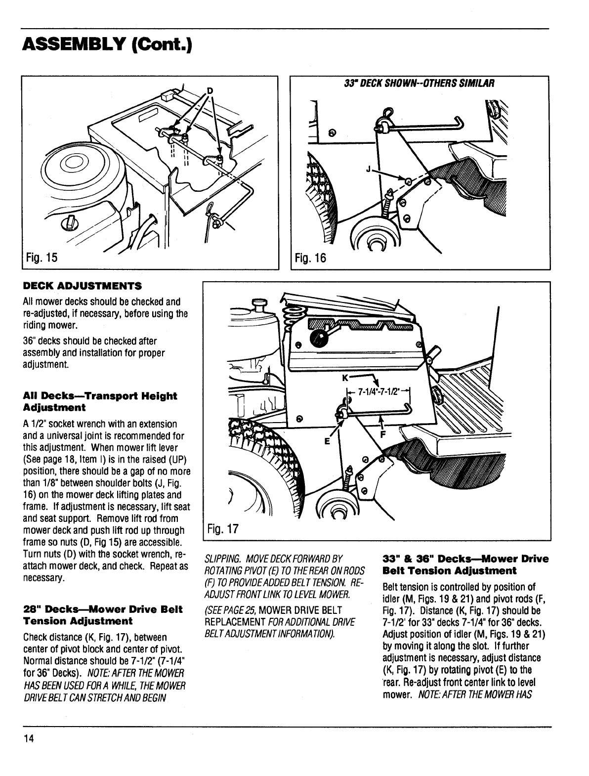
All DecksmTransport Height
Adjustment
A 1/2" socketwrenchwithan extension
and a universaljoint is recommended for
thisadjustment. When mowerlift lever
(See page18, Item I)is inthe raised(UP)
position,there shouldbe a gapof no more
than1/8"betweenshoulderbolts(J, Fig.
16) onthe mowerdeckliftingplates and
frame. If adjustmentis necessary,lift seat
andseatsupport. Removelift rodfrom
mowerdeckandpush lift rod upthrough
frameso nuts(D, Fig15) areaccessible.
Turnnuts(D) with the socketwrench,re-
attachmowerdeck,and check. Repeatas
necessary.
28" Decks_Mower Drive Belt
Tension Adjustment
Check distance (K, Fig.17), between
centerof pivot block andcenterof pivot.
Normal distanceshouldbe7-1/2" (7-1/4"
for36" Decks). NOTE'AFTERTHEMOWER
HASBEENUSEDFORA WHILE,THEMOWER
DRIVEBELTCANSTRETCHANDBEGIN
Fig.17
SLIPPING.MOVEDECKFORWARDBY
ROTATINGPIVOT(E)TOTHEREARONROOS
(F) TOPROVIDEADDEDBELTTENSION.RE-
ADJUSTFRONTLINKTOLEVELMOWER.
(SEEPAGE25,MOWERDRIVEBELT
REPLACEMENTFORADOITIONALDRIVE
BELTADJUSTMENTINFORMATION).
33" & 36" Decks-Mower Drive
Belt Tension Adjustment
Belttensionis controlledby positionof
idler(M, Figs.19 & 21) and pivot rods(F,
Fig.17). Distance(K, Fig.17) shouldbe
7-1/2' for 33" decks7-1/4"for 36"decks.
Adjustpositionof idler(M, Figs.19 & 21)
by movingit alongthe slot. If further
adjustmentis necessary,adjustdistance
(K, Fig.17) byrotatingpivot(E) to the
rear. Re-adjustfrontcenterlinkto level
mower. NOTE'AFTERTHEMOWB_HAS
14
ASSEMBLY (Cont.)
BEENUSEDFORA WHILE,THEMOWER
DRIVEBELTCANSTRETCHANDBEGIN
SLIPPING.MOVEDECKFORWARDBY
RELOCATINGPIVOT(E)ONPIVOTRODS(F)
TOADDBELTTENSION.RE-ADJUSTFRONT
CENTERLINKTOLEVELMOWER.
(SEEPAGE25,MOWERDRIVE BELT
REPLACEMENTFORADOITIONALDRIVE
BELTADJUSTMENTINFORMATION).
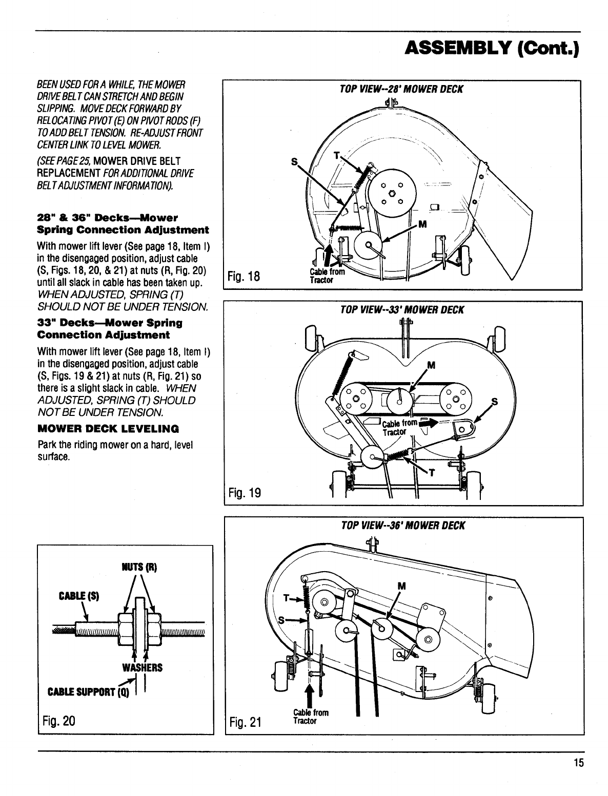
28" & 36" Decks--Mower
Spring Connection Adjustment
With mowerlift lever(See page18, Item I)
inthe disengagedposition, adjustcable
(S, Figs.18, 20, & 21)at nuts(R, Fig.20)
untilall slackin cablehas beentakenup.
WHEN ADJUSTED, SPRING (T)
SHOULD NOT BE UNDER TENSION.
33" Decks--Mower Spring
Connection Adjustment
With mower lift lever (See page18, Item I)
in the disengaged position, adjustcable
(S, Figs.19 &21) at nuts(R, Fig.21) so
thereis a slightslackin cable. WHEN
ADJUSTED, SPRING (T) SHOULD
NOT BE UNDER TENSION.
MOWER DECK LEVELING
Park the riding mower on a hard, level
surface.
Fig.18
Fig.19
S
TOP VlEW--2r MOWERDECK
Cablefrom
Tractor
TOPVIEW--33'MOWERDECK
CaLE(S)
NUTS(_
WASHERS
CMLE SUPPORT(Q_) I
Fig.20 Fig.21 Cablefrom
Tractor
TOPVIEW--36' MOWERDECK
15
ASSEMBLY (Cont.)
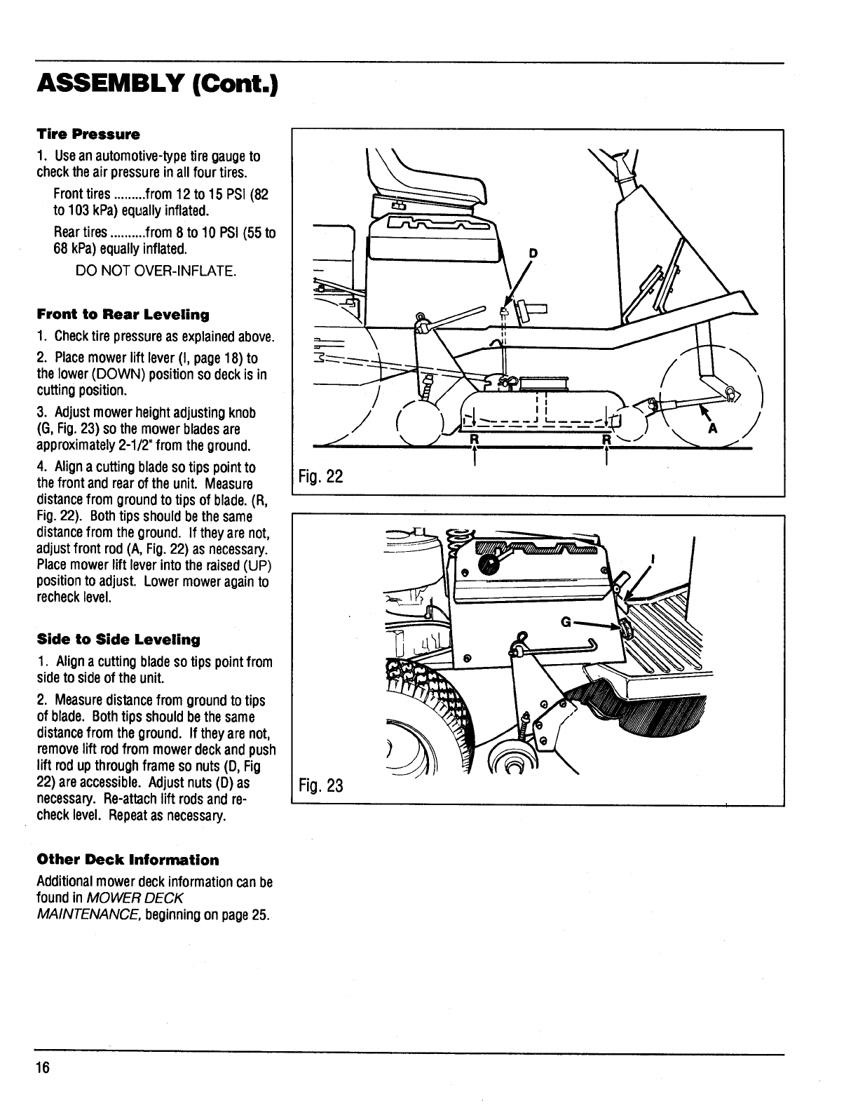
Tire Pressure
1. Usean automotive-typetire gaugeto
checkthe air pressurein allfour tires.
Fronttires.........from 12 to 15 PSI (82
to 103 kPa) equallyinflated.
Reartires..........from 8 to 10 PSI (55 to
68 kPa)equallyinflated.
DO NOT OVER-INFLATE.
Front to Rear Leveling
1. Checktire pressureas explainedabove.
2. Place mowerliftlever(I, page 18) to
the lower(DOWN) position so deckis in
cuttingposition.
3. Adjustmowerheight adjustingknob
(G, Fig.23) so the mower bladesare
approximately2-1/2"from the ground.
4. Aligna cuttingbladeso tips point to
the front and rearof the unit. Measure
distancefrom ground to tipsof blade. (R,
Fig.22). Bothtipsshouldbethe same
distancefrom the ground. If they are not,
adjustfront rod (A, Fig.22) as necessary.
Place mowerlift leverinto the raised(UP)
positionto adjust. Lowermoweragainto
recheck level.
Side to Side Leveling
1. Aligna cuttingbladeso tipspointfrom
sideto sideof the unit.
2. Measuredistancefrom groundto tips
of blade. Bothtips shouldbe the same
distancefrom the ground. If theyare not,
removelift rodfrom mowerdeckandpush
lift rod upthroughframe so nuts(D, Fig
22) are accessible.Adjustnuts(D) as
necessary. Re-attachlift rodsand re-
checklevel. Repeatas necessary.
Fig.22
Fig.23
D
R
1
A
Other Deck Information
Additional mowerdeck informationcan be
found inMOWER DECK
MAINTENANCE, beginningon page 25.
16
CONTROLS AND OPERATION
E
Fig.24
G
Fig.25
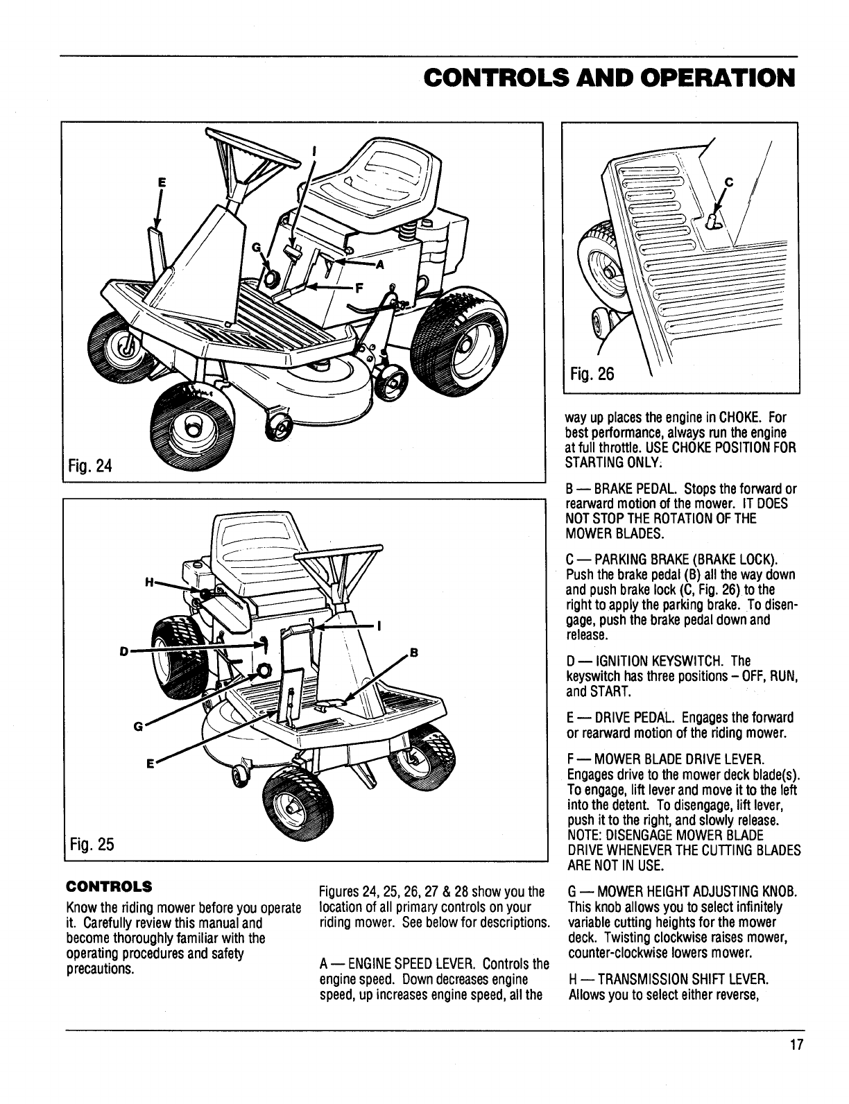
CONTROLS
Know the riding mower before you operate
it. Carefully review this manual and
becomethoroughly familiar with the
operatingprocedures andsafety
precautions.
Figures24, 25, 26, 27 & 28 show you the
location of all primary controls on your
riding mower. Seebelow for descriptions.
A-- ENGINESPEEDLEVER. Controlsthe
engine speed. Downdecreasesengine
speed,upincreases enginespeed,allthe
way up placesthe engine in CHOKE. For
best performance, always run the engine
at full throttle. USECHOKEPOSITIONFOR
STARTINGONLY;
B-- BRAKEPEDAL. Stops the forward or
rearwardmotionof the mower. IT DOES
NOTSTOPTHEROTATIONOFTHE
MOWERBLADES.
C-- PARKINGBRAKE(BRAKELOCK).
Pushthe brakepedal (B) all the waydown
andpush brakelock(C, Fig.26) to the
rightto applythe parkingbrake.To disen-
gage, push the brake pedaldownand
release.
D D IGNITIONKEYSWlTCH.The
keyswitch has three positions - OFF,RUN,
and START.
E-- DRIVEPEDAL. Engagesthe forward
or rearward motionof the riding mower.
F-- MOWER BLADEDRIVELEVER.
Engagesdrive to the mowerdeck blade(s).
To engage,lift lever and move it to the left
into the detent. To disengage,lift lever,
push it to the right, and slowly release.
NOTE:DISENGAGEMOWERBLADE
DRIVEWHENEVERTHE CUTTINGBLADES
ARENOTIN USE.
G-- MOWERHEIGHTADJUSTINGKNOB.
This knob allows you to select infinitely
variable cutting heights for the mower
deck. Twisting clockwise raises mower,
counter-clockwise lowers mower.
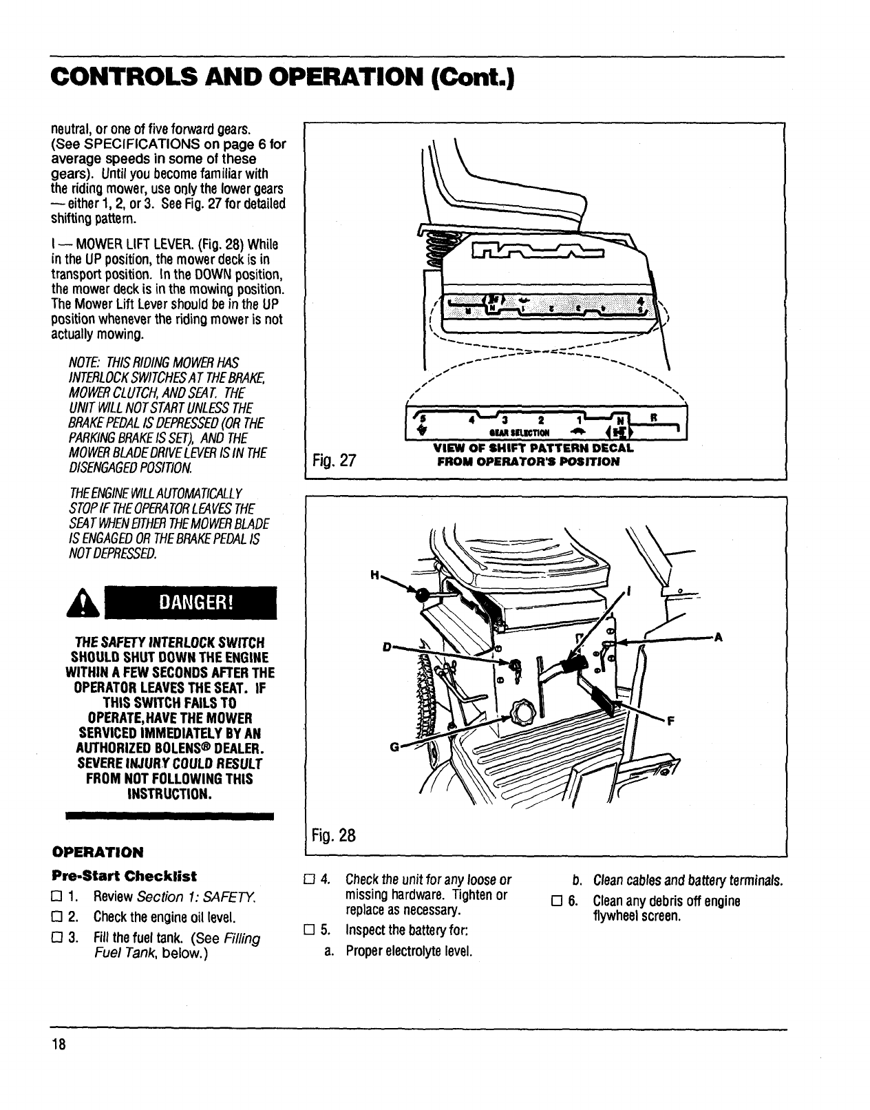
H--TRANSMISSION SHIFTLEVER.
Allows you to select eitherreverse,
17
CONTROLS AND OPERATION (Cont.)
neutral,or oneof five forward gears.
(See SPECIFICATIONS on page 6 for
average speeds in some of these
gears). Until you become familiar with
the riding mower, use onlythe lower gears
either 1, 2, or 3. SeeFig.27 for detailed
shifting pattern.
I-- MOWER LIFT LEVER.(Fig.28) While
in the UP position, the mower deck is in
transport position. In the DOWN position,
the mower deck is inthe mowing position.
The Mower Lift Lever should be in the UP
position wheneverthe riding mower is not
actually mowing.
NOTE: THISRIDINGMOWERHAS
INTERLOCKSWITCHESAT THEBRAKE,
MOWERCLUTCH,ANDSEAT.THE
UNITWILLNOTSTARTUNLESSTHE
BRAKEPEDALIS DEPRESSED(ORTHE
PARKINGBRAKEISSET),ANDTHE
MOWERBLADEDRIVELEVERISIN THE
DISENGAGEDPOSITION.
THEENGINEWILLAUTOMATICALLY
STOPIF THEOPERATORLEAVESTHE
SEAT WHENEITHERTHEMOWERBLADE
ISENGAGEDORTHEBRAKEPEDALIS
NOTDEPRESSED.
THESAFETYINTERLOCKSWITCH
SHOULDSHUT DOWNTHEENGINE
WITHIN A FEWSECONDSAFTERTHE
OPERATORLEAVESTHESEAT. IF
THIS SWITCH FAILSTO
OPERATE,HAVETHE MOWER
SERVICEDIMMEDIATELYBYAN
AUTHORIZEDBOLENS®DEALER.
SEVEREINJURYCOULDRESULT
FROM NOTFOLLOWINGTHIS
INSTRUCTION.
II III
OPERATION
Pre-Start Checklist
[] 1. ReviewSection 1: SAFETY.
[] 2. Checkthe engineoil level.
[] 3. Fillthe fuel tank. (See Filling
Fuel Tank, below.)
Fig.27
Fig.28
r-14.
1-15.
a.
VIEW OF SHIFT PATTERN DECAL
FROM OPERATOR_POSITION
Checkthe unitfor any loose or
missing hardware. Tighten or
replaceas necessary.
Inspect the batteryfor:
Proper electrolyte level.
Cleancablesand battery terminals.
Cleanany debrisoff engine
flywheelscreen.
18
CONTROLS AND OPERATION (Cont.)
_7.
O10.
[311.
[] 12.
[] 13
Checktire inflation:
Fronttires:from 12 to 15 PSI (82 to
103 kPa) equallyinflated.
Reartires:from 8 to 10 PSi (55 to
68 kPa)equallyinflated.
DO NOT OVER-INFLATE,
Re-connectsparkplug,_ireto
sparkplug.
Make suremowerdischarge
deflectorshieldis securely
fastened to the right-handsideof
mowerdeck (28 & 36 inch decks).
Adjustseatto a comfortable
position. (See page 8, Seat
Adjustment.
Ct_eckareato be_o_. e,_,_
anydebrisfrom thisarea.
Setparkingbrake.
Place transmission shift lever (rite
N (Neutral) (Fig.2_').
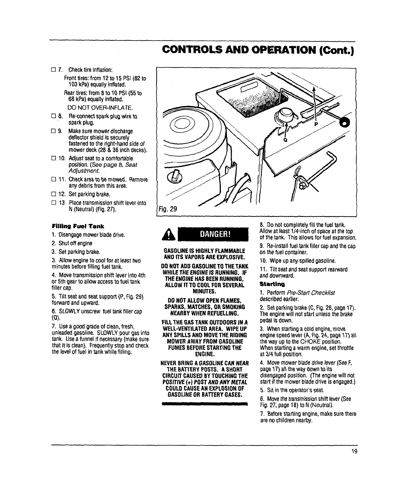
Filling Fuel Tank
1. Disengagemowerbladedrive.
2. Shut offengine
3. Set parking brake.
3. Allow engine to coolfor at least two
minutes before filling fuel tank.
4. Move transmission shift lever into 4th
or 5th gear to allow accessto fuel tank
filler cap.
5. Tilt seatand seat support (P, Fio. 29)
forward and upward.
6. SLOWLY unscrew fuel tank filler cap
(o).
7. Useagood grade of clean,fresh,
unleadedgasoline. SLOWLYpour gas into
tank. Usea funnel if necessary(make sure
that it is clean). Frequentlystop and check
the level of fuel in tank white_illing.
GASOUNEIS HIGHLYFLAMMABLE
AND ITSVAPORSAREEXPLOSIVE,,
OQNOTADDGASOLINETO THETARK
WHILETHEENGINEIS RUNNING. IF
THEENGINEHASBEENRUNNING,
ALLOWITTO COOLFORSEVERAL
MINUTES.
DONOTALLOWOPENFLAMES,
SPARKS,MATCHES,ORSMOKING
NEARBYWHENREFUELLING.
F|LLTHE GASTANKOUTDOORSIN A
WELL-VENTILATEDAREA. WIPEUP
Ally SPILLSMiD MOVETHE RIDING
MOWERAWAYFROMGASOLINE
FUMES BEFORESTARTINGTHE
ENGINE.
NEVERBRINGA GASOLINECANNEAR
THE BATTERYPOSTS. A SHORT
CIRCUITCAUSEDBYTOUCHINGTHE
POSITIVE(+) POSTANDANY METAL
COULDCAUSEANEXPLOSIONOF
GASOLINEOR BATTERYGASES.
8. Do notcompletelyflitthefuel tank.
Allowat least1/4-inch of spaceat the top
of the tank. This allowsfor fuel expansion.
9. Re-instal} fuel tank fillercap andthe cap
on the fuel container.
10. Wipe upany spilledgasoline,
11. Tilt seatandseatsupportrearward
and downward.
Starting
1. PerformPre-Start Checklist
_scribed earlier.
2. Set parkingbrake(C, Fig.26, page17).
Theenginewill not startunless the brake
pe_l is down.
3. When startinga cord engine,m_
enginespeed I_v_r(A, Fi_.2_,,pa_e17} all
the wayupto theCHOKE position.
Whenstarting a warm engine,setthrottle
at 3/4 full position.
4. Movemower bladedrivelever(SeeF,
page17) art the way (lownto its
disengaged position. (The enginewill not
start if the mowerbladedrive is engaged.)
5. Sit in the operator'sseat.
6. Move the transmissionshift lever(See
Fig.27, page18) to N (Neutral).
7. Belore starting engine,makesure there
are no childrennearby.
19
CONTROLS AND OPERATION (Cont.)
8. Place ignitionkey in keyswitch andturn
keyto the START position. Releasekey
as soon as the enginestarts.
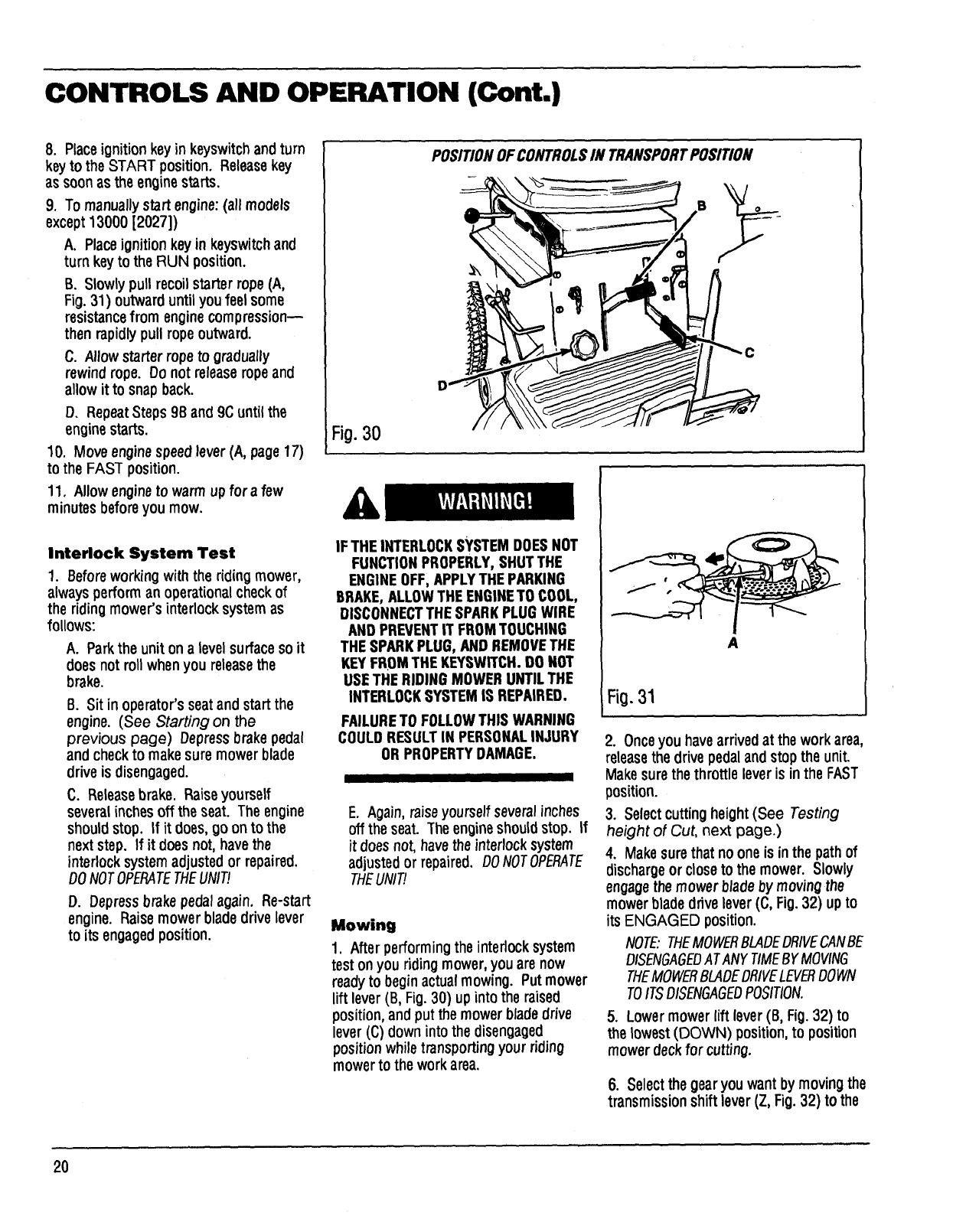
9. To manuallystart engine:(all models
except 13000 [2027])
A. Place ignitionkey in keyswitch and
turn keyto the RUN position.
B. Slowly pull recoilstarter rope (A,
Fig.31) outward until you feel some
resistancefrom engine compression--
then rapidly pull rope outward.
C. Allowstarterrope to gradually
rewindrope. Do not releaseropeand
allow it to snapback.
D. RepeatSteps9B and 9C untilthe
enginestarts.
10. Move enginespeedlever (A, page17)
to the FAST position.
11. Allowengineto warm up for a few
minutes before you mow.
Interlock System Test
1. Before working with the riding mower,
always performan operational check of
the riding mower's interlocksystem as
follows:
A. Parkthe unit ona level surface so it
does not roll when you releasethe
brake.
B. Sit in operator's seatand start the
engine. (See Starting on the
previous page) Depressbrakepedal
and check to make sure mower blade
drive is disengaged.
C. Releasebrake. Raiseyourself
several inchesoff the seat. The engine
should stop. If it does, go on to the
next step. If it does not, havethe
interlock system adjusted or repaired.
DONOTOPERATETHEUNIT!
D. Depress brake pedalagain. Re-start
engine. Raisemower blade drive lever
to its engagedposition.
POSITIONOFCONTROLSIN TRANSPORTPOSITION
f
Fig.30
IF THEINTERLOCKSYSTEMDOESNOT
FUNCTIONPROPERLY,SHUTTHE
ENGINEOFF,APPLYTHEPARKING
BRAKE,ALLOWTHEENGINETO COOL,
DISCONNECTTHESPARKPLUGWIRE
AND PREVENTIT FROMTOUCHING
THESPARKPLUG,AND REMOVETHE
KEYFROMTHE KEYSWITCH.DO NOT
USETHERIDING MOWERUNTILTHE
INTERLOCKSYSTEMIS REPAIRED.
FAILURETO FOLLOWTHIS WARNING
COULDRESULTIN PERSONALINJURY
OR PROPERTYDAMAGE.
I IIII IIIIII
E. Again,raise yourself severalinches
off the seat. The engineshouldstop. If
it does not, have the interlock system
adjusted or repaired. DONOTOPERATE
THEUNIT!
Mowing
1. After performing the interlock system
teston youridingmower,youare now
readyto beginactualmowing. Put mower
liftlever(B, Fig.30) up intothe raised
position,and putthemowerbladedrive
lever(C) down into the disengaged
positionwhile transportingyour riding
mowerto the workarea.
A
Fig.31
2. Onceyou have arrived at the work area,
releasethe drive pedal andstop the unit.
Make sure the throttle lever is in the FAST
position.
3. Selectcutting height(See Testing
height of Cut, next page.)
4. Makesure that no one is in the path of
discharge or close to the mower. Slowly
engagethe mower bladeby moving the
mower blade drive lever (C, Fig.32) up to
its ENGAGED position.
NOTE:THEMOWERBLADEDRIVECANBE
DISENGAGEDATANYTIMEBYMOVING
THEMOWERBLADEDRIVELEVERDOWN
TOITSDISENGAGEOPOSITION.
5. Lower mower lift lever (B, Fig.32) to
the lowest (DOWN) position, to position
mower deck for cutting.
6. Select the gearyou want by moving the
transmission shiftlever(Z, Fig.32) to the
20
CONTROLS AND OPERATION (Cont.)
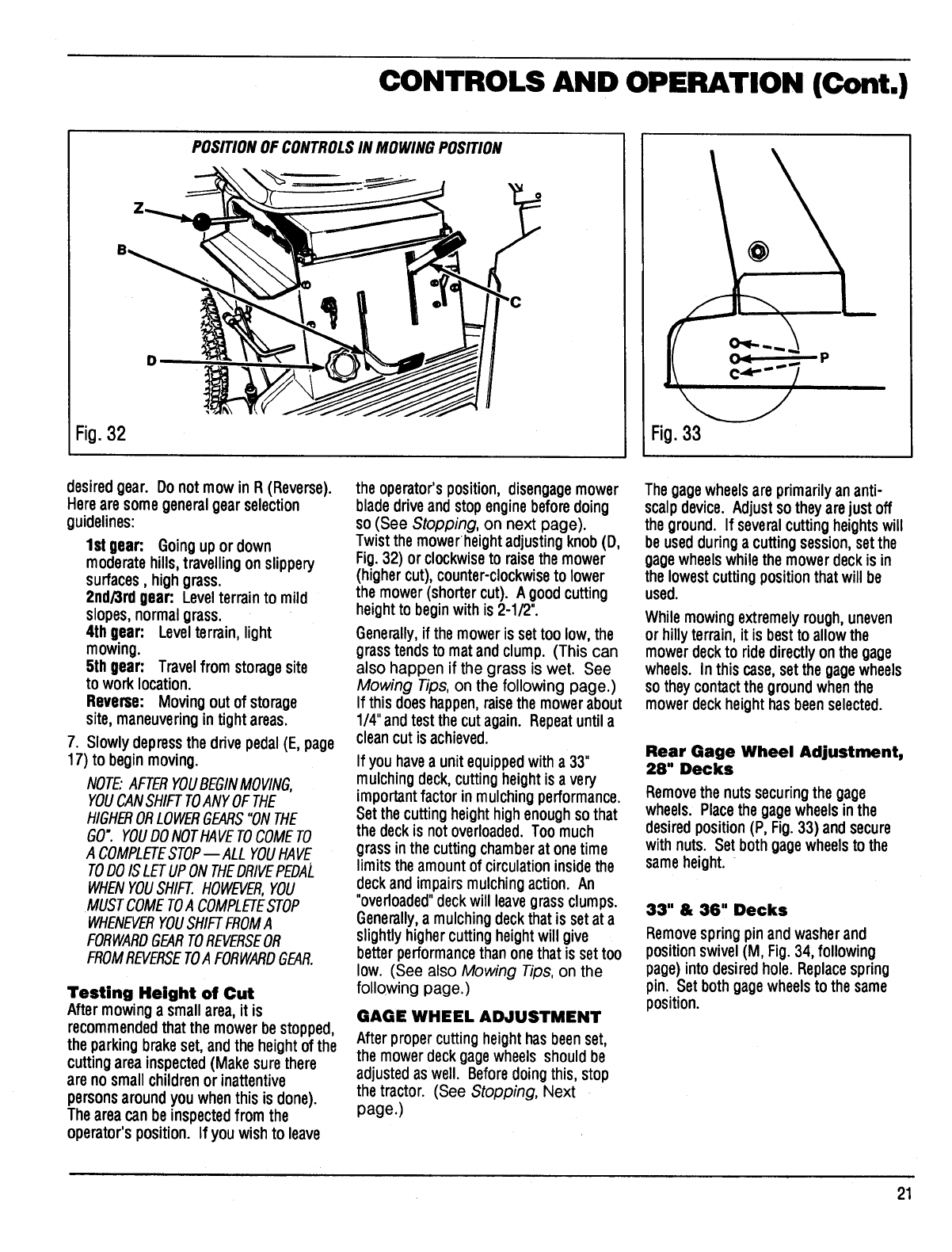
Fig.32
POSITIONOF CONTROLSIN MOWINGPOSITION
Fig.33
P
desiredgear. Donot mow in R (Reverse).
Hereare somegeneralgearselection
guidelines:
1st gear: Goingupor down
moderatehills,travellingon slippery
surfaces, highgrass.
2nd/3rd gear: Levelterrainto mild
slopes,normalgrass.
4th gear: Levelterrain,light
mowing.
5th gear: Travelfrom storagesite
to work location.
Reverse: Movingoutof storage
site,maneuveringintightareas.
7. Slowly depressthe drive pedal(E, page
17) to beginmoving.
NOTE:AFTERYOUBEGINMOVING,
YOUCANSHIFTTOANYOFTHE
HIGHERORLOWERGEARS"ONTHE
GO". YOUDONOTHAVETOCOMETO
A COMPLETESTOP--ALLYOUHAVE
TOO0IS LETUPONTHEORIVEPEOAL
WHENYOUSHIFI_.HOWEVER,YOU
MUSTCOMETOA COMPLETESTOP
WHENEVERYOUSHIFTFROMA
FORWAROGEARTOREVERSEOR
FROMREVERSETOA FORWAROGEAR.
Testing Height of Cut
Aftermowing a smallarea,it is
recommended thatthe mowerbe stopped,
the parkingbrakeset, andthe height of the
cuttingarea inspected(Make surethere
are no smallchildrenor inattentive
persons aroundyouwhenthis is done).
Thearea can be inspectedfromthe
operator'sposition. If youwishto leave
the operator'sposition, disengagemower
bladedrive andstopenginebefore doing
so (See Stopping, on next page).
Twistthe mowerheightadjustingknob(D,
Fig.32) or clockwiseto raisethemower
(highercut), counter-clockwiseto lower
the mower(shortercut). A goodcutting
heightto beginwith is 2-1/2".
Generally,if the moweris settoolow, the
grasstendsto mat andclump. (This can
also happen if the grass is wet. See
Mowing Tips, on the following page.)
If thisdoeshappen,raisethe mowerabout
1/4"andtestthe cutagain. Repeatuntila
cleancut isachieved.
If you havea unit equippedwitha 33"
mulching deck, cuttingheight is a very
importantfactorinmulchingperformance.
Setthe cuttingheighthighenoughsothat
the deckis notoverloaded.Too much
grassinthe cutting chamberat onetime
limitstheamountof circulationinsidethe
deckandimpairsmulchingaction. An
"overloaded"deckwill leavegrassclumps.
Generally,a mulchingdeckthatis setat a
slightlyhighercutting heightwill give
betterperformancethanonethatis settoo
low. (See also Mowing Tips, on the
following page.)
GAGE WHEEL ADJUSTMENT
Nter proper cuttingheight has beenset,
the mower deck gagewheels should be
adjusted as well. Before doing this, stop
the tractor. (See Stopping, Next
page.)
Thegagewheelsare primarilyan anti-
scalpdevice. Adjustsothey arejustoff
theground. If severalcuttingheightswill
be usedduringa cuttingsession,setthe
gagewheelswhilethe mowerdeckis in
the lowestcuttingpositionthat will be
used.
While mowingextremelyrough, uneven
or hilly terrain, it is best to allow the
mowerdeckto ridedirectlyonthe gage
wheels. In thiscase, setthe gagewheels
so they contactthe groundwhenthe
mowerdeckheight has beenselected.
Rear Gage Wheel Adjustment,
28" Decks
Removethe nuts securingthe gage
wheels. Placethe gagewheelsinthe
desiredposition (P, Fig.33) andsecure
withnuts. Set both gagewheelsto the
sameheight.
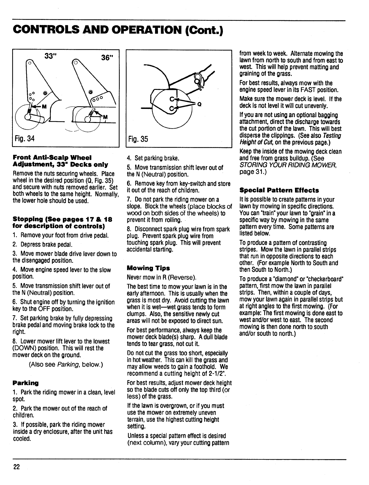
33"& 36"Decks
Removespring pin andwasherand
position swivel(M, Fig.34, following
page)into desiredhole. Replacespring
pin. Set bothgagewheelsto the same
position.
21
CONTROLS AND OPERATION (Cont.)
33"
Fig.34 35
Fi0.
Front Anti.Scalp Wheel
Adjustment, 33" Decks only
Removethe nutssecuringwheels. Place
wheelinthe desiredposition (Q, Fig.35)
andsecurewith nutsremovedearlier. Set
bothwheelsto the sameheight. Normally,
the lowerhole shouldbe used.
Stopping (See pages 17 & 18
for description of controls)
1. Removeyour foot from drivepedal.
2. Depressbrakepedal.
3. Movemowerblade driveleverdownto
the disengagedposition.
4. Moveenginespeedleverto the slow
position.
5. Movetransmissionshiftleveroutof
the N(Neutral) position.
6. Shutengineoff byturningthe ignition
keyto the OFF position.
7. Set parking brake byfully depressing
brakepedaland movingbrakelockto the
right.
8. Lowermowerliftleverto the lowest
(DOWN) position. Thiswill restthe
mowerdeck onthe ground.
(Also see Parking, below.)
Parking
1. Parkthe ridingmowerina clean,level
spot.
2. Park the mowerout of the reachof
children.
3. If possible, parkthe ridingmower
insidea dryenclosure,afterthe unit has
cooled.
4. Setparkingbrake.
5. Movetransmissionshiftleveroutof
the N(Neutral) position.
6. Removekeyfrom key-switchandstore
it out of the reachof children.
7. Donot parkthe ridingmowerona
slope. Blockthewheels(place blocks of
wood on both sidesOfthe wheels) to
prevent it from rolling.
8. Disconnectsparkplugwirefrom spark
plug. Preventsparkplug wirefrom
touchingsparkplug. This will prevent
accidentalstarting.
Mowing Tips
Nevermow in R(Reverse).
Thebesttime to mowyour lawnis inthe
earlyafternoon. Thisis usuallywhenthe
grassis mostdry. Avoidcuttingthe lawn
whenit is wet--wet grasstendsto form
clumps. Also,thesensitivenewlycut
areaswill notbe exposedto directsun.
Forbest performance,alwayskeepthe
mowerdeckblade(s)sharp. A dullblade
tendsto tear grass,notcut it.
Donotcut the grasstooshort,especially
in hotweather.Thiscankill the grassand
mayallow weedsto gain afoothold. We
recommenda cutting heightof 2-1/2".
Forbestresults, adjust mowerdeckheight
so the bladecutsoff onlythetop third(or
less) of the grass.
If the lawnis overgrown,orif youmust
usethe moweronextremely uneven
terrain,use thehighestcuttingheight
setting.
Unlessa specialpatterneffectis desired
(next column), varyyourcuttingpattern
from weekto week. Alternatemowingthe
lawnfrom northto southandfrom eastto
west. Thiswill helppreventmattingand
grainingof the grass.
Forbest results,alwaysmow withthe
enginespeedleverin its FAST position.
Makesurethe mowerdeckis level. If the
deckis notlevelitwill cut unevenly.
If youare not usingan optionalbagging
attachment,directthe dischargetowards
the cut portionof the lawn. Thiswill best
dispersethe clippings. (Seealso Testing
Heightof Cut,on the previouspage.)
Keepthe insideof the mowingdeckclean
andfree fromgrassbuildup.(See
STORING YOUR RIDING MOWER,
page 31.)
Special Pattern Effects
It is possibleto createpatternsinyour
lawnby mowinginspecificdirections.
You can"train"your lawnto "grain"ina
specificwayby mowinginthe same
pattern everytime. Some patterns are
listedbelow.
To producea patternof contrasting
stripes. Mowthe lawnin parallelstrips
that run inoppositedirectionsto each
other. (ForexampleNorth to South and
thenSouthto North.)
To produce a"diamond"or "checkerboard"
pattern,firstmow the lawnin parallel
strips. Then,withinacoupleof days,
mowyour lawnagain inparallel stripsbut
at rightanglesto thefirst mowing. (For
example:Thefirst mowingis doneeastto
westand/orwestto east. Thesecond
mowingisthen donenorthto .south
and/or southto north.)
22
MAINTENANCE
TRACTOR MAINTENANCE
Engine
FORSPECIFICENGINEMAINTENANCE
INSTRUCTIONS,REFERTOENGINEOWNER'S
MANUALSUPPLIEOWITHTHERIOING
MOWER.THEENGINEOWNER'SMANUAL
INCLUBESINSTRUCTIONSFORCHECKING
ENGINEOILLEVEL,CHANGINGENGINEOIL,
INSPECTINGANOCLEANINGENGINEAIR
FILTER,IGNITIONSYSTEMMAINTENANCE,
ANOOTHERIMPORTANTENGINE
MAINTENANCEINFORMATION.FOR
FURTHERREPAIRS,CONTACTYOURLOCAL
BOLENS_OEALER.
Lubrication
Refer to MaintenanceChart on Page32 for
lubrication instructions.
Interlock System Test
This riding mower is equippedwithan
interlocksystem. Thissystempreventsthe
operatorfrom startingthe engine,if:
1.) ...thereis no onein theseat.
2.) ...thebrakepedalis notdepressed.
3.) ...themowerbladedriveleveris in the
engagedposition.
IF THEINTERLOCKSYSTEMDOESNOT
FUNCTIONPROPERLY,SHUTTHE
ENGINEOFF, APPLYTHE PARKING
BRAKE,ALLOWTHE ENGINETO COOL,
DISCONNECTTHESPARKPLUGWIRE
AND PREVENTIT FROMTOUCHING
THESPARKPLUG, AND REMOVETHE
KEYFROMTHE KEYSWITCH.DO NOT
USETHE RIDING MOWERUNTILTHE
INTERLOCKSYSTEMIS REPAIRED.
FAILURETO FOLLOWTHIS WARNING
COULDRESULTIN PERSONALINJURY
OR PROPERTYDAMAGE.
See Interlock System Test on page
20, inthe CONTROLS AND
OPERATION section to perform this test.
I
I
I
n--.== ,,=,..= L,.._= _% _"'= _ '=""==
./% !_ r----..._ 3/16.,_1/4.
__ \ (5-6 mm)
Fig.36
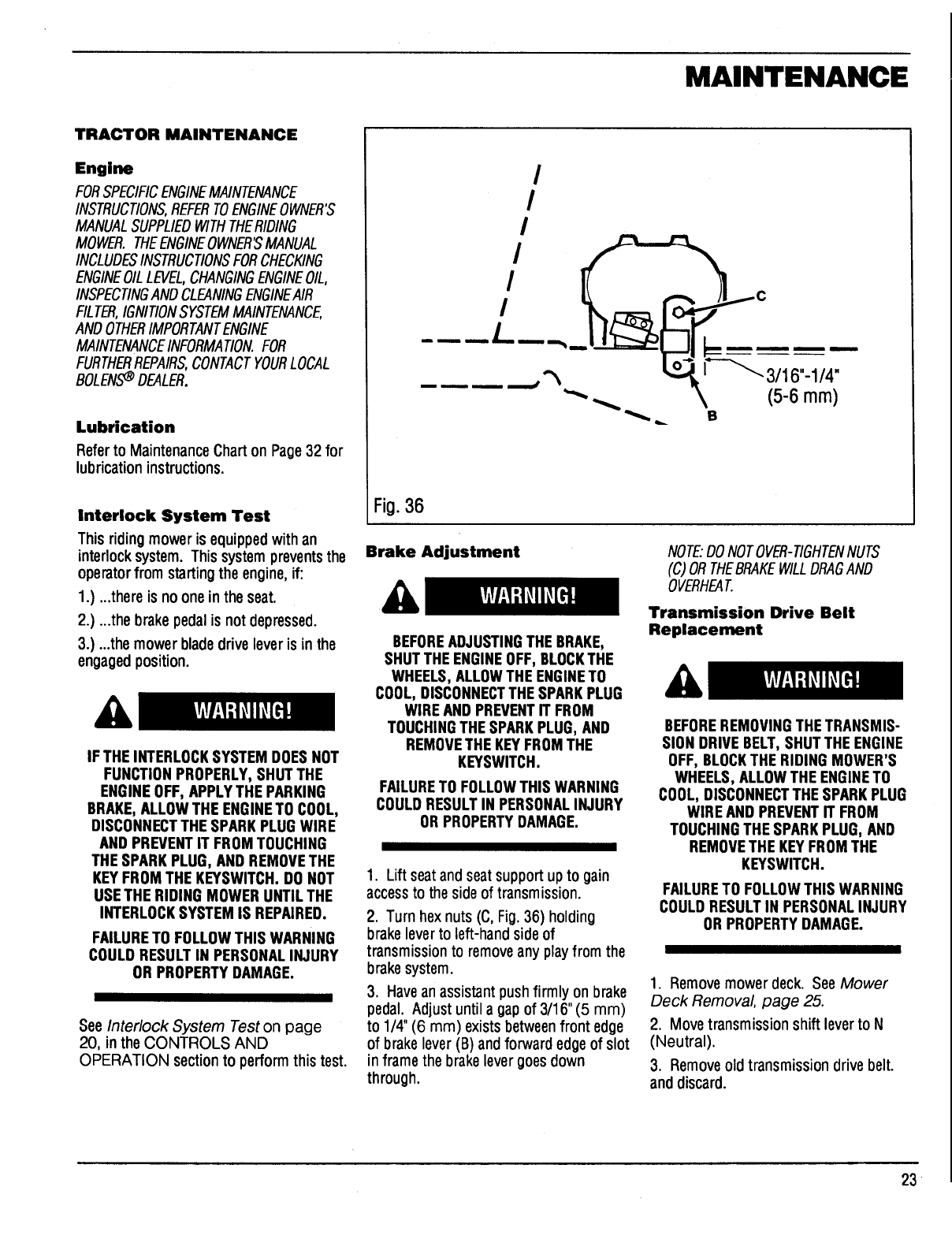
Brake Adjustment
BEFOREADJUSTINGTHE BRAKE,
SHUTTHE ENGINEOFF, BLOCKTHE
WHEELS,ALLOWTHEENGINETO
COOL,DISCONNECTTHESPARKPLUG
WIRE ANDPREVENTIT FROM
TOUCHINGTHESPARKPLUG,AND
REMOVETHE KEYFROMTHE
KEYSWITCH.
FAILURETO FOLLOWTHIS WARNING
COULDRESULTIN PERSONALINJURY
OR PROPERTYDAMAGE.
1. Lift seat and seatsupport up to gain
accessto the side of transmission.
2. Turnhex nuts (C, Fig.36) holding
brake lever to left-hand side of
transmission to removeany play from the
brake system.
3. Havean assistant push firmly on brake
pedal. Adjust until a gap of 3/16" (5 mm)
to 1/4" (6 mrn) exists betweenfront edge
of brake lever (B) and forward edgeof slot
in frame the brake lever goes down
through.
NOTE."DONOTOVER-TIGHTENNUTS
(C)ORTHEBRAKEWILLORAGANO
OVERHEAT
Transmission Drive Belt
Replacement
BEFOREREMOVINGTHETRANSMIS-
SIONDRIVEBELT,SHUTTHE ENGINE
OFF, BLOCKTHE RIDING MOWER'S
WHEELS,ALLOWTHEENGINETO
COOL,DISCONNECTTHE SPARKPLUG
WIREAND PREVENTIT FROM
TOUCHINGTHESPARKPLUG,AND
REMOVETHE KEYFROMTHE
KEYSWITCH.
FAILURETO FOLLOWTHIS WARNING
COULDRESULTIN PERSONALINJURY
OR PROPERTYDAMAGE.
1. Remove mower deck. See Mower
Deck Removal, page 25.
2. Move transmission shift lever to N
(Neutral).
3. Remove old transmission drive belt.
and discard.
23
MAINTENANCE (Cont.)
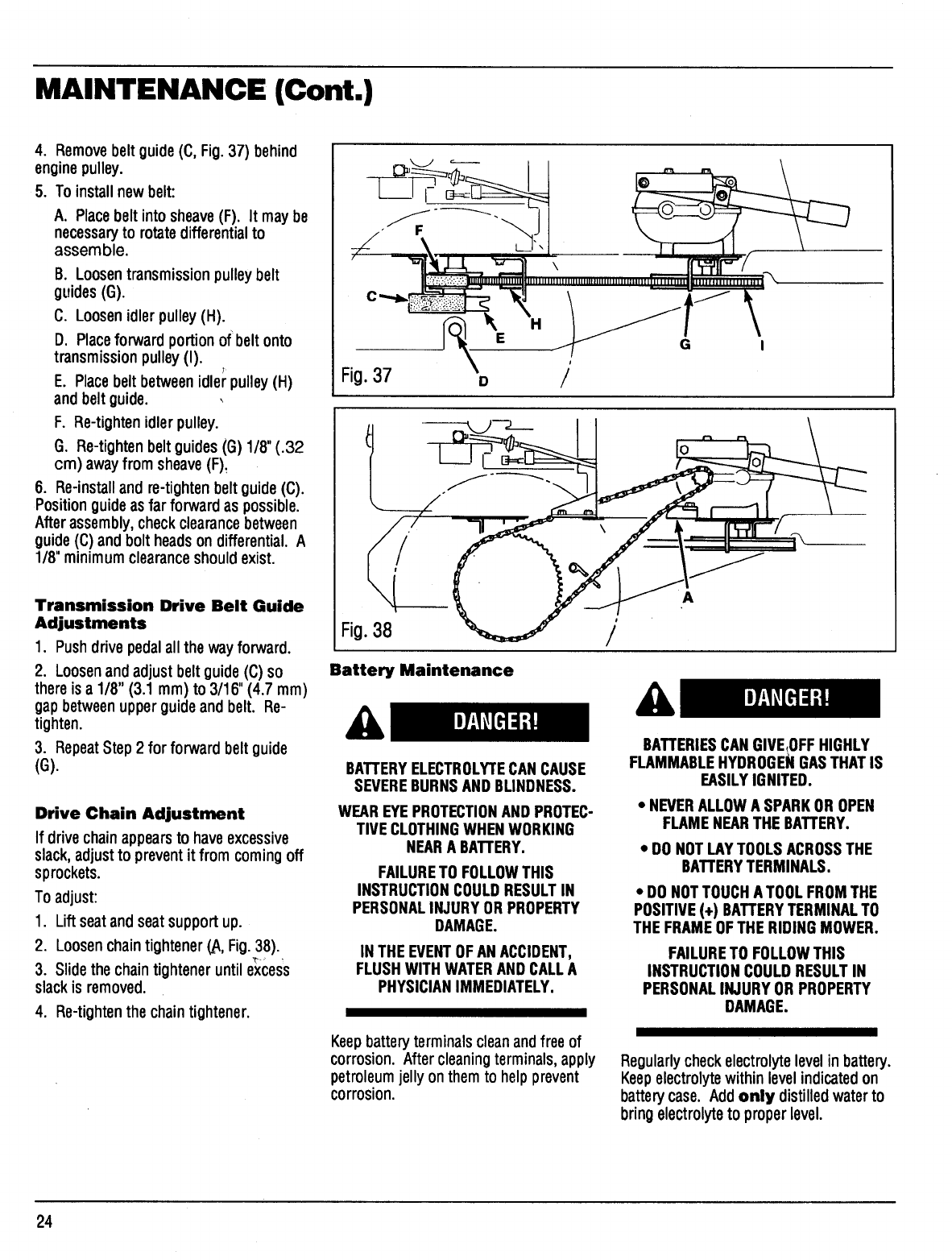
4. Removebeltguide(C, Fig.37) behind
enginepulley.
5. To installnew belt:
A. Placebeltintosheave(F). It may be
necessaryto rotatedifferentialto
assemble.
B. Loosentransmissionpulleybelt
guides(G).
C. Loosenidlerpulley(H).
D. Placeforward portion of beltonto
transmissionpulley (I).
E. Placebeltbetweenidlerpulley (H)
and beltguide.
F. Re-tightenidlerpulley.
G. Re-tightenbeltguides(G) 1/8" (.32
cm) awayfrom sheave(F).
6. Re-installand re-tightenbeltguide(C).
Positionguideas far forward as possible.
Afterassembly,checkclearancebetween
guide(C) and bolt headsondifferential. A
1/8"minimumclearanceshouldexist.
Transmission Drive Belt Guide
Adjustments
1. Pushdrive pedalall the wayforward.
2. Loosenandadjust beltguide(C) so
thereis a 1/8" (3.1 mm) to 3/16" (4.7 mm)
gapbetweenupperguideandbelt. Re-
tighten.
3. RepeatStep 2for forward beltguide
(G).
Drive Chain Adjustment
If drivechainappearsto haveexcessive
slack,adjustto prevent it from comingoff
sprockets.
To adjust:
1. Liftseatandseatsupportup.
2. LoosenchaintightenerLA,Fig.38).
3. Slidethe chaintighteneruntilexcess
slackis removed.
4. Re-tighten the chaintightener.
\
Fig.37 D/
A
Fig.38 /
Battery Maintenance
BATTERYELECTROLYTECANCAUSE
SEVEREBURNSANDBLINDNESS.
WEAREYEPROTECTIONAND PROTEC-
TIVECLOTHINGWHENWORKING
NEARA BATTERY.
FAILURETO FOLLOWTHIS
INSTRUCTIONCOULDRESULTIN
PERSONALINJURYOR PROPERTY
DAMAGE.
IN THE EVENTOFANACCIDENT,
FLUSHWITH WATERAND CALLA
PHYSICIANIMMEDIATELY.
BATTERIESCANGIVE,OFFHIGHLY
FLAMMABLEHYDROGENGASTHATIS
EASILYIGNITED.
• NEVERALLOWA SPARKOR OPEN
FLAMENEARTHE BATTERY.
• DO NOTLAYTOOLSACROSSTHE
BATTERYTERMINALS.
• DO NOTTOUCHATOOL FROMTHE
POSITIVE(+) BATTERYTERMINALTO
THEFRAMEOFTHE RIDINGMOWER.
FAILURETO FOLLOWTHIS
INSTRUCTIONCOULDRESULTIN
PERSONALINJURYOR PROPERTY
DAMAGE.
Keepbattery terminals cleanandfree of
corrosion.After cleaningterminals, apply
petroleum jelly on them to help prevent
corrosion.
Regularly checkelectrolytelevel inbattery.
Keepelectrolyte withinlevel indicatedon
batterycase. Addonly distilledwaterto
bringelectrolyteto properlevel.
24
MAINTENANCE (Cont.)
MOWER DECK MAINTENANCE
Mower Deck Removal
BEFOREREMOVINGOR RE-
INSTALLINGTHEMOWER DECK,SHUT
THE ENGINEOFF, APPLYTHE
PARKINGBRAKE,ALLOWTHE ENGINE
TO COOL,DISCONNECTTHESPARK
PLUGWIRE ANDPREVENTIT FROM
TOUCHINGTHESPARKPLUG, AND
REMOVETHE KEYFROM THE
KEYSWITCH.
FAILURETO FOLLOWTHIS
INSTRUCTIONCOULDRESULTIN
PERSONALINJURYORPROPERTY
DAMAGE.
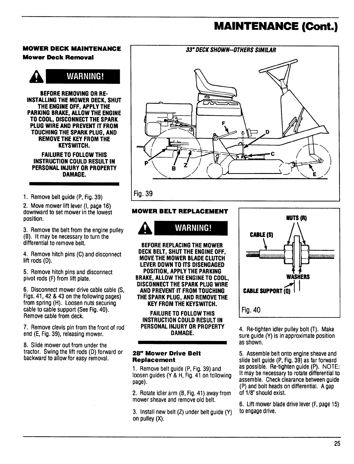
1. Removebelt guide(P, Fig. 39)
2. Move mower lift lever (I, page 16)
downward to set mower in the lowest
position.
3. Removethe belt from the engine pulley
(B). It may benecessaryto turn the
differential to remove belt.
4. Removehitchpins(C)anddisconnect
lift rods(D).
5. Remove hitch pins and disconnect
pivot rods (F) from lift plate.
6. Disconnectmower drivecable cable (S,
Figs. 41,42 & 43 on the following pages)
from spring (H). Loosen nuts securing
cableto cable support (SeeFig. 40).
Removecable from deck.
7. Remove clevis pin from the front of rod
end (E, Fig. 39), releasing mower.
8. Slide mower out from under the
tractor. Swing the lift rods (D) forward or
backward to allow for easy removal.
33" DECKSHOWN--OTHERSSIMILAR
Fig.39
MOWER BELT REPLACEMENT
BEFOREREPLACINGTHEMOWER
DECKBELT,SHUTTHE ENGINEOFF,
MOVETHEMOWERBLADECLUTCH
LEVERDOWNTO ITS DISENGAGED
POSITION,APPLYTHEPARKING
BRAKE,ALLOWTHEENGINETO COOL,
DISCONNECTTHESPARKPLUGWIRE
ANDPREVENTIT FROMTOUCHING
THESPARKPLUG,ANDREMOVETHE
KEYFROMTHEKEYSWITCH.
FAILURETO FOLLOWTHIS
INSTRUCTIONCOULDRESULTIN
PERSONALINJURYOR PROPERTY
DAMAGE.
28" Mower Drive Belt
Replacement
1. Remove belt guide (P, Fig.39) and
loosenguides (Y & H, Fig.41 onfollowing
page).
2. Rotate idler arm (B, Fig.41) awayfrom
mower sheaveand removeold belt.
3. Install new belt (Z) under belt guide (Y)
on pulley (X),
NUTS(It)
WASHERS
CULE SUPPORT(Q_) I
Fig.40
4. Re-tighten idler pulley bolt (T). Make
sure guide(Y) is in approximate position
as shown.
5. Assemble belt ontoenginesheaveand
slidebelt guide(P, Fig.39) asfar forward
as possible. Re-tighten guide(P). NOTE:
It may be necessaryto rotatedifferential to
assemble. Check clearancebetweenguide
(P) and bolt heads on differential. Agap
of 1/8" should exist.
6. Lift mower bladedrive lever (F,page15)
to engagedrive.
25
MAINTENANCE (Cont.)
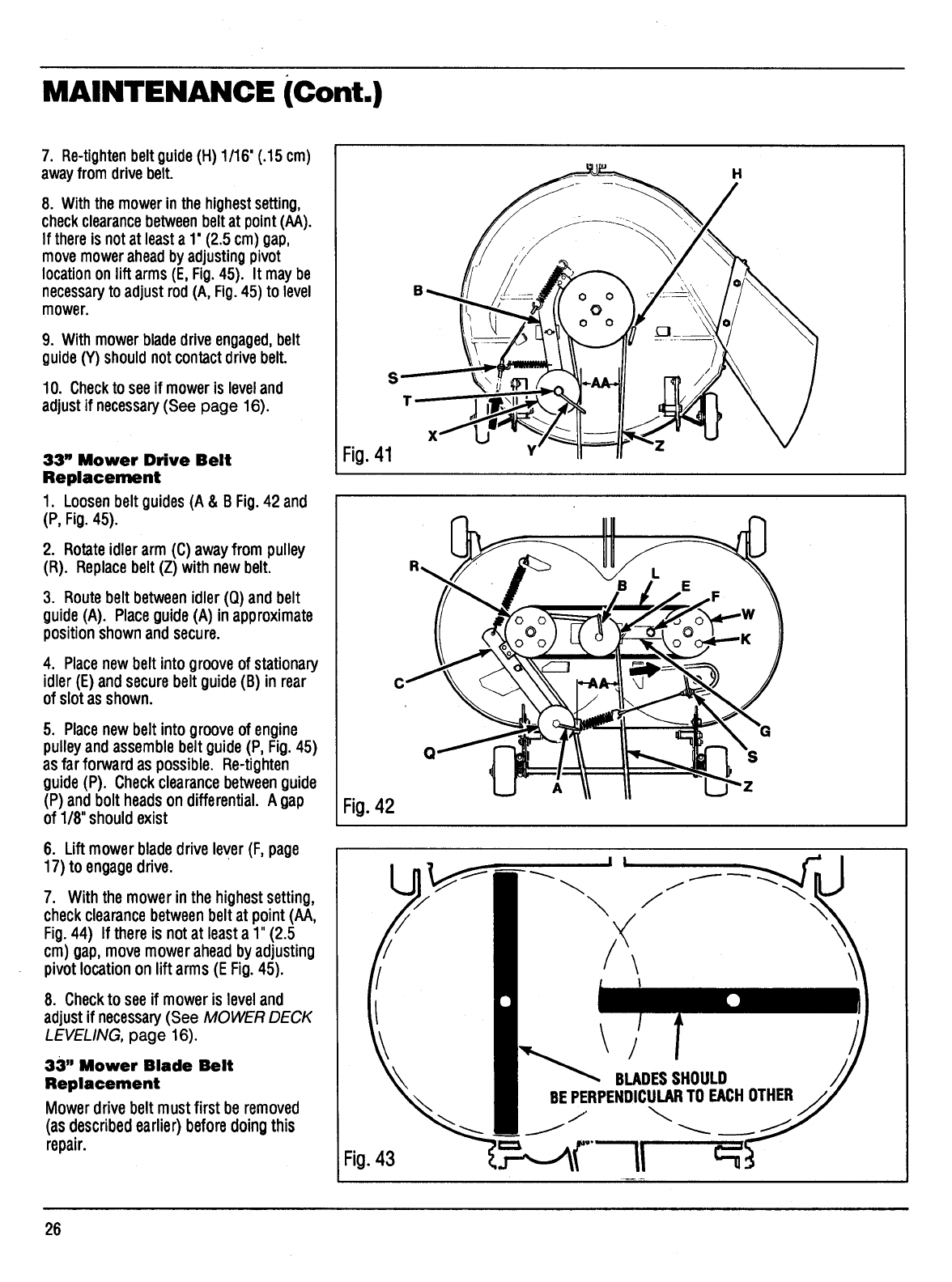
7. Re-tighten beltguide(H) 1/16' (.15 cm)
awayfrom drivebelt.
8. With the mower in the highestsetting,
checkclearancebetweenbelt at point (AA).
If there is not at least a 1' (2.5 cm) gap,
movemower aheadby adjusting pivot
location onlift arms (E, Fig.45). It may be
necessaryto adjust rod (A, Fig. 45) to level
mower.
9. With mowerbladedriveengaged,belt
guide (Y) should notcontactdrive belt.
10. Checkto seeif moweris leveland
adjustif necessary(See page 16).
33" Mower Drive Belt
Replacement
1. Loosen belt guides (A & B Fig.42 and
(P, Fig.45).
2. Rotate idler arm (C) away from pulley
(R). Replacebelt (Z) with new belt.
3. Route beltbetweenidler(Q) and belt
guide (A). Place guide(A) in approximate
position shownandsecure.
4. Placenew belt into groove of stationary
idler (E)and secure belt guide(B) in rear
of slot as shown.
5. Placenew belt into groove of engine
pulley andassemblebelt guide (P, Fig.45)
as far forward as possible. Re-tighten
guide (P). Check clearancebetween guide
(P) and bolt heads on differential. A gap
of 1/8" should exist
6. Lift mower bladedrive lever (F, page
17) to engagedrive.
7. With the mower in the highest setting,
checkclearance betweenbelt at point (AA,
Fig.44) If there is not at least a 1" (2.5
cm) gap, move mower ahead by adjusting
pivot location on lift arms (E Fig.45).
8. Checkto see if mower is level and
adjust if necessary(See MOWER DECK
LEVELING, page 16).
33" Mower Blade Belt
Replacement
Mowerdrive belt must first be removed
(as describedearlier) beforedoingthis
repair.
Fig.41
Fig.42
Fig.43
H
Y
A
S
f
\/
\I
\/
BLADESSHOULD
BEPERPENDICULARTO EACHOTHER
/
26
MAINTENANCE (Cont.)
J S
Fig.44
C
33" DECKSHOWN-OTHERSSIMILAR
\
Fig.45
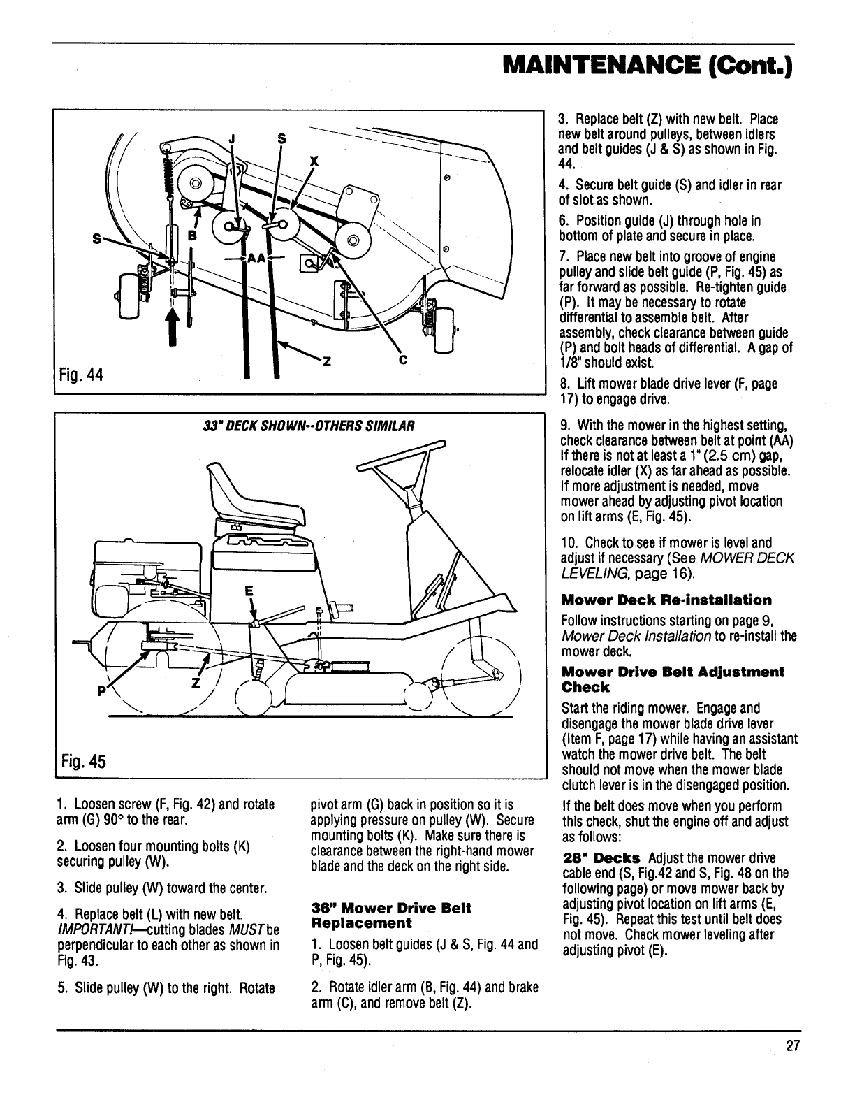
1. Loosen screw (F, Fig.42) and rotate
arm (G) 90° to the rear.
2. Loosenfour mountingbolts(K)
securingpulley (W).
3. Slide pulley (W) toward the center.
4. Replacebelt (L) withnew belt.
IMPORTANT._--cuttingblades MUSTbe
perpendicular to each other as shown in
Fig. 43.
5. Slide pulley(W) to the right. Rotate
pivot arm (G) back in position so it is
applying pressure onpulley (W). Secure
mounting bolts (K). Makesure there is
clearancebetweenthe right-hand mower
blade and the deck on the right side.
36" Mower Drive Belt
Replacement
1. Loosenbelt guides (J & S, Fig.44 and
P, Fig.45).
2. Rotateidlerarm(B, Fig.44) andbrake
arm(C),andremovebelt(Z).
3. Replacebelt(Z) with new belt. Place
new belt aroundpulleys,betweenidlers
and beltguides(J & S) asshownin Fig.
44.
4, Secure beltguide(S) andidler in rear
of slotasshown.
6. Positionguide(J) throughholein
bottomof plateand securein place.
7. Placenewbeltintogrooveof engine
pulley andslidebeltguide(P, Fig.45) as
far forward as possible. Re-tightenguide
(P). It maybe necessaryto rotate
differentialto assemblebelt. After
assembly,checkclearancebetweenguide
(P) andbolt headsof differential.A gapof
1/8"shouldexist.
8. Liftmowerblade drivelever (F,page
17) to engagedrive.
9. With the mower in the highestsetting,
checkclearancebetweenbelt at point (AA)
If thereis notat leasta 1"(2.5 cm) gap,
relocateidler(X) asfar aheadas possible.
If moreadjustmentis needed,move
moweraheadbyadjustingpivot location
on liftarms (E, Fig.45).
10. Checktosee if mower is level and
adjustif necessary(See MOWER DECK
LEVELING, page 16),
Mower Deck Re-installation
Follow instructions startingonpage9,
Mower Deck Installation to re-install the
mower deck.
Mower Drive Belt Adjustment
Check
Start the riding mower. Engageand
disengagethe mowerbladedrivelever
(Item F, page17) while having an assistant
watch the mower drive belt. The belt
should not move when the mower blade
clutch lever is in the disengaged position.
If the belt does move when you perform
this check,shut the engineoff andadjust
as follows:
28" Decks Adjustthe mower ddve
cableend(S, Fig.42and S, Fig. 48 on the
followingpage)or move mowerbackby
adjustingpivotlocationonliftarms (E,
Fig.45). Repeat.thistestuntilbeltdoes
not move. Checkmowerlevelingafter
adjustingpivot(E).
27
MAINTENANCE (Cont.)
33" & 36" Decks Adjustthe mower
drivecableend(S, Figs.42 &44 andS,
Fig.48 on thefollowing page) or relocate
theadjustablepulley(B, Fig.42 or X, Fig.
44) withinits slot onthe idlersupport
bracket. If furtheradjustmentis
necessary,move moweraheadby
adjustingpivot locationon liftarms (E,
Fig.45). Repeatthistest untilbeltdoes
not move. Checkmowerlevelingafter
adjustingpivots (E).
MOWER DECK BRAKE
ADJUSTMENTS
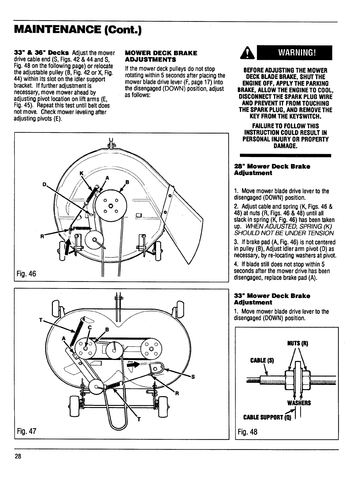
If the mower deck pulleys do not stop
rotatingwithin5 seconds after placingthe
mowerblade drivelever(F, page17) into
the disengaged(DOWN) position, adjust
as follows:
Fig.46
BEFOREADJUSTINGTHE MOWER
DECKBLADEBRAKE,SHUTTHE
ENGINEOFF,APPLYTHEPARKING
BRAKE,ALLOWTHE ENGINETO COOL,
DISCONNECTTHESPARKPLUGWIRE
AND PREVENTIT FROMTOUCHING
THESPARKPLUG, ANDREMOVETHE
KEYFROMTHEKEYSWITCH.
FAILURETO FOLLOWTHIS
INSTRUCTIONCOULDRESULTIN
PERSONALINJURYOR PROPERTY
DAMAGE.
28" Mower Deck Brake
Adjustment
1. Movemowerbladedrive leverto the
disengaged(DOWN) position.
2. Adjustcableand spring(K, Figs.46 &
48) at nuts(R, Figs.46 & 48) untilall
slackinspring(K, Fig.46) has beentaken
up. WHEN ADJUSTED, SPRING (K)
SHOULD NOT BE UNDER TENSION
3. If brakepad(A, Fig.46) is notcentered
in pulley(B), Adjustidlerarm pivot(D) as
necessary,by re-locatingwashersat pivot.
4. If bladestill does notstopwithin5
secondsafter the mowerdrivehas been
disengaged,replacebrakepad(A).
Fig.47
T
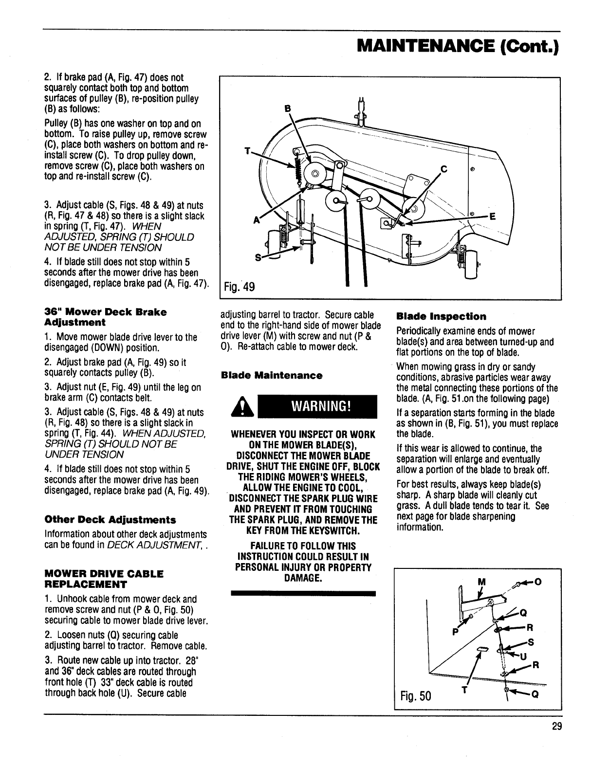
33" Mower Deck Brake
Adjustment
1. Movemower bladedrivelever to the
disengaged(DOWN) position.
NUTS(_
cuue_t._(s) __ \\\\\_\\\\\\\\\_
WASHERS
CABLESUPPORT(Q_) i
Fi0.48
28
MAINTENANCE (Cont.)
2. If brakepad (A, Fig.47) doesnot
squarelycontactbothtopand bottom
surfacesof pulley (B), re-positionpulley
(B) asfollows:
Pulley(B) hasonewasheron topandon
bottom. To raisepulleyup, removescrew
(C), placebothwashersonbottomand re-
installscrew(C). To droppulley down,
removescrew (C), place bothwasherson
topand re-installscrew(C).
3. Adjust cable(S, Figs. 48 & 49) at nuts
(R, Fig.47 &48) so there is a slight slack
in spring(T, Fig.47). WHEN
ADJUSTED, SPR/NG (T) SHOULD
NOT BE UNDER TENSION
4. If bladestilldoesnotstopwithin5
secondsafter the mowerdrivehas been
disengaged,replacebrakepad (A, Fig.47).
36" Mower Deck Brake
Adjustment
1. Movemower blade drive lever to the
disengaged(DOWN) position.
2. Adjustbrakepad (A, Fig.49) so it
squarelycontactspulley (B).
3. Adjustnut(E, Fig.49) untilthe legon
brakearm (C) contactsbelt.
3. Adjustcable(S, Figs.48 & 49) at nuts
(R, Fig.48) sothere isa slightslackin
spring(T, Fig.44). WHEN ADJUSTED,
SPR/NG (T) SHOULD NOT BE
UNDER TENS/ON
4. If blade still does not stop within5
seconds afterthe mower drive has been
disengaged, replace brake pad (A, Fig. 49).
Other Deck Adjustments
Information about otherdeckadjustments
can befound in DECK ADJUSTMENT,.
MOWER DRIVE CABLE
REPLACEMENT
1. Unhookcable from mower deckand
remove screw andnut (P &O, Fig.50)
securing cable to mower blade drive lever.
2. Loosen nuts (Q) securing cable
adjusting barrel to tractor. Remove cable.
3. Route new cableup into tractor. 28"
and36" deck cablesare routed through
front hole (T) 33" deck cable is routed
through back hole (U). Secure cable
B
Fig.49
adjustingbarrel to tractor. Secure cable
endto the right-hand side of mower blade
drive lever (M) with screw and nut (P &
0). Re-attachcable to mower deck.
Blade Maintenance
WHENEVERYOU INSPECTORWORK
ONTHEMOWERBLADE(S),
DISCONNECTTHEMOWERBLADE
DRIVE, SHUTTHEENGINEOFF, BLOCK
THERIDING MOWER'SWHEELS,
ALLOWTHEENGINETO COOL,
DISCONNECTTHESPARKPLUGWIRE
AND PREVENTIT FROMTOUCHING
THESPARKPLUG,ANDREMOVETHE
KEYFROMTHE KEYSWITCH.
FAILURETO FOLLOWTHIS
INSTRUCTIONCOULDRESULTIN
PERSONALINJURYOR PROPERTY
DAMAGE.
Blade Inspection
Periodicallyexamineendsof mower
blade(s) and area betweenturned-up and
flat portions onthe top of blade.
When mowinggrassin dryor sandy
conditions,abrasiveparticleswear away
the metalconnectingtheseportions of the
blade.(A, Fig.51.on thefollowingpage)
If a separationstartsformingin the blade
as shownin (B, Fig.51), youmust replace
the blade.
If this wear is allowedto continue,the
separationwill enlargeandeventually
allow a portion of the blade to break off.
For best results, always keep blade(s)
sharp. A sharp bladewill cleanlycut
grass. A dull bladetends to tear it. See
next pagefor bladesharpening
information.
Fig.50
29
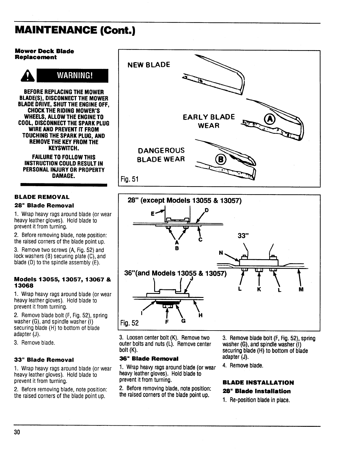
MAINTENANCE (Cont.)
Mower Deck Blade
Replacement
BEFOREREPLACINGTHEMOWER
BLADE(S),DISCONNECTTHE MOWER
BLADEDRIVE, SHUTTHE ENGINEOFF,
CHOCKTHE RIDING MOWER'S
WHEELS,ALLOWTHE ENGINETO
COOL,DISCONNECTTHE SPARKPLUG
WIRE AND PREVENTIT FROM
TOUCHINGTHESPARKPLUG, AND
REMOVETHEKEYFROMTHE
KEYSWITCH.
FAILURETO FOLLOWTHIS
INSTRUCTIONCOULDRESULTIN
PERSONALINJURYOR PROPERTY
DAMAGE.
NEW BLADE ,__
EARLY BLADE
WEAR
DANGEROUS
BLADE WEAR
Fig. 51
BLADE REMOVAL
28" Blade Removal
1. Wrap heavy rags around blade (or wear
heavyleather gloves). Hold bladeto
prevent it from turning.
2. Before removing blade, note position:
the raised corners of the blade point up.
3. Removetwo screws (A, Fig. 52) and
lock washers (B) securing plate (C),and
blade(D) to the spindle assembly (E).
Models 13055, 13057, 13067 &
13068
1. Wrap heavy rags around blade (or wear
heavyleather gloves). Hold blade to
prevent it from turning.
2. Removeblade bolt (F, Fig. 52), spring
washer (G), and spindle washer (I)
securing blade (H) to bottom of blade
adapter (J).
3. Remove blade.
33" Blade Removal
1. Wrap heavy rags around blade (or wear
heavyleather gloves). Hold blade to
prevent it from turning.
2. Before removing blade, note position:
the raised corners of the bladepoint up.
Fig.52
28" (except Models 13055 & 13057)
A
B
33"
36"(and Models 13055 & 13057)
F G
3. Loosen center bolt (K). Removetwo
outer bolts and nuts (L). Removecenter
bolt (K).
36" Blade Removal
1. Wrap heavy ragsaroundblade(or wear
heavy leathergloves). Hold bladeto
preventit from turning.
2. Beforeremovingblade,noteposition:
the raisedcornersof the bladepointup.
3. Removebladebolt (F, Fig.52), spring
washer(G), andspindlewasher(I)
securingblade(H) to bottomof blade
adapter(J).
4. Removeblade.
BLADE INSTALLATION
28" Blade Installation
1. Re-p0siti0nblade in place.
3O
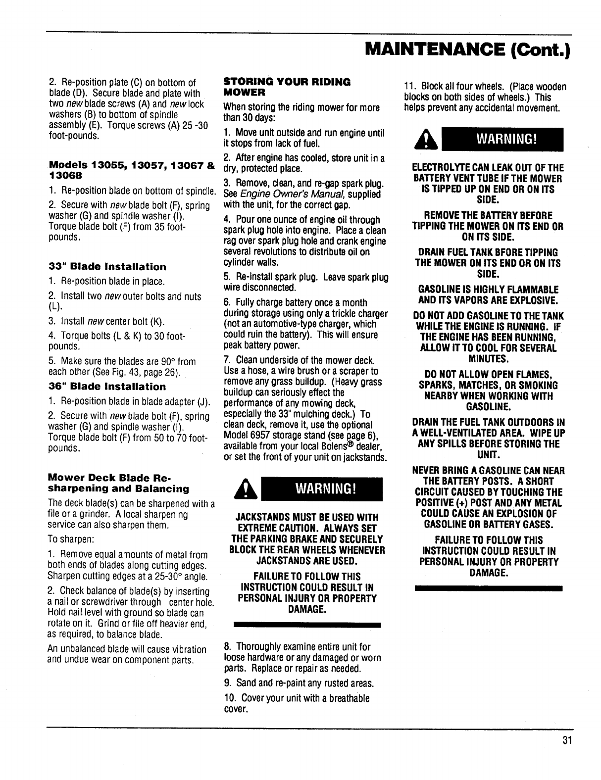
MAINTENANCE (Cont.)
2. Re-position plate(C) on bottom of
blade(D). Secure bladeand plate with
two new blade screws (A) and new lock
washers (B) to bottom of spindle
assembly (E). Torque screws (A) 25 -30
foot-pounds.
Models 13055, 13057, 13067 &
13068
1. Re-position blade on bottom of spindle.
2. Secure with newblade bolt (F), spring
washer (G) and spindle washer (I).
Torque blade bolt (F) from 35 foot-
pounds.
33" Blade Installation
1. Re-position blade in place.
2. Install two newouter bolts and nuts
(L).
3. Install newcenter bolt (K).
4. Torque bolts (L & K) to 30 foot-
pounds.
5. Makesure the blades are 90° from
each other (See Fig. 43, page 26).
36" Blade Installation
1. Re-position blade in blade adapter (J).
2. Secure with newblade bolt (F), spring
washer (G) and spindle washer (I).
Torque blade bolt (F) from 50 to 70 foot-
pounds.
Mower Deck Blade Re.
sharpening and Balancing
The deck blade(s) can be sharpenedwith a
file or a grinder. A localsharpening
service can also sharpen them.
To sharpen:
1. Remove equalamounts of metal from
both ends of bladesalong cutting edges.
Sharpencutting edgesat a 25-30° angle.
2. Check balance of blade(s) by inserting
a nail or screwdriver through center hole.
Hold nail level with ground so blade can
rotate on it. Grind or file off heavierend,
as required, to balance blade.
An unbalanced bladewill causevibration
and undue wear on component parts.
STORING YOUR RIDING
MOWER
When storingtheriding mowerfor more
than 30 days:
1. Moveunitoutsideand runengineuntil
it stopsfromlackof fuel.
2. Afterengine hascooled,storeunitin a
dry, protected place.
3. Remove,clean,and re-gapsparkplug.
SeeEngine Owner's Manual supplied
with theunit,for thecorrectgap.
4. Pouroneounceof engineoil through
sparkplug holeinto engine. Placea clean
ragoversparkplug holeandcrankengine
severalrevolutionsto distributeoil on
cylinderwalls.
5. Re-installsparkplug. Leavesparkplug
wire disconnected.
6. Fullychargebatteryoncea month
duringstorageusing onlya trickle charger
(not an automotive-typecharger,which
could ruin the battery). Thiswill ensure
peak battery power.
7. Cleanundersideof the mowerdeck.
Usea hose,a wirebrushor ascraperto
removeanygrassbuildup. (Heavygrass
buildupcanseriouslyeffectthe
performanceof any mowingdeck,
especiallythe 33"mulchingdeck.) To
cleandeck,removeit, usethe optional
Model6957 storagestand(see page6),
availablefromyour localBolens dealer,
or setthefront ofyour unitonjackstands.
JACKSTANDSMUST BEUSEDWITH
EXTREMECAUTION. ALWAYSSET
THE PARKINGBRAKEAND SECURELY
BLOCKTHEREARWHEELSWHENEVER
JACKSTANDSAREUSED.
FAILURETO FOLLOWTHIS
INSTRUCTIONCOULDRESULTIN
PERSONALINJURYOR PROPERTY
DAMAGE.
8. Thoroughlyexamineentireunit for
loose hardware or any damagedor worn
parts. Replaceor repair asneeded.
9. Sandand re-paint any rustedareas.
10. Coveryourunitwitha breathable
cover.
11. Blockallfour wheels. (Placewooden
blockson bothsidesof wheels.) This
helps preventany accidentalmovement.
ELECTROLYTECANLEAKOUTOFTHE
BATTERYVENTTUBEIF THEMOWER
IS TIPPEDUP ON ENDORON ITS
SIDE.
REMOVETHEBATrERYBEFORE
TIPPINGTHE MOWERON ITS ENDOR
ONITS SIDE.
DRAIN FUELTANKBFORETIPPING
THEMOWERON ITSENDOR ON ITS
SIDE.
GASOLINEIS HIGHLYFLAMMABLE
AND ITSVAPORSAREEXPLOSIVE.
DO NOTADDGASOLINETOTHETANK
WHILETHEENGINEIS RUNNING. IF
THEENGINEHASBEENRUNNING,
ALLOWITTO COOLFORSEVERAL
MINUTES.
DO NOTALLOWOPENFLAMES,
SPARKS,MATCHES,ORSMOKING
NEARBYWHENWORKINGWITH
GASOLINE.
DRAINTHEFUELTANKOUTDOORSIN
A WELL-VENTILATEDAREA. WIPEUP
ANYSPILLSBEFORESTORINGTHE
UNIT.
NEVERBRINGA GASOLINECANNEAR
THEBATTERYPOSTS. A SHORT
CIRCUITCAUSEDBYTOUCHINGTHE
POSITIVE(+) POSTAND ANYMETAL
COULDCAUSEANEXPLOSIONOF
GASOLINEOR BATTERYGASES.
FAILURETO FOLLOWTHIS
INSTRUCTIONCOULDRESULTIN
PERSONALINJURYORPROPERTY
DAMAGE.
31
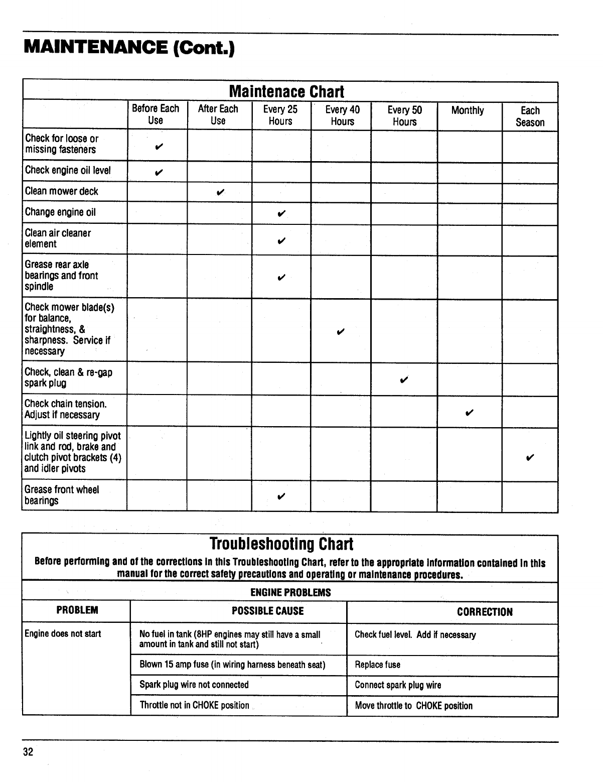
MAINTENANCE (Cont.)
Maintenace Chart
BeforeEach AfterEach Every25 Every40 Every50 Monthly Each
Use Use Hours Hours Hours Season
Checkfor looseor
missingfasteners v'
Checkengineoil level i,,
Cleanmowerdeck v'
Changeengineoil
Cleanair cleaner
element
Greaserearaxle
bearingsandfront
spindle
Checkmowerblade(s)
for balance,
straightness,&
sharpness. Serviceif
necessary
Check,clean& re-gap
sparkplug
Check chaintension.
Adjustif necessary
Lightlyoil steeringpivot
linkand rod,brakeand
clutchpivot brackets(4)
andidlerpivots
Greasefrontwheel
bearings
i,,'
i/
vs
v'
v'
11
v'
TroubleshootingChart
Before performingandof the correctionsIn thisTroubleshootingChart, referto the appropriateinformationcontainedin this
manual forthe correctsafetyprecautionsandoperatingor maintenanceprocedures.
ENGINEPROBLEMS
PROBLEM POSSIBLECAUSE CORRECTION
Enginedoesnotstart Nofuelintank(8HPenginesmaystillhavea small Checkfuellevel.Addifnecessary
amountintankandstillnotstart)
Blown15ampfuse(inwiringharnessbeneathseat) Replacefuse
Sparkplugwirenotconnected Connectsparkplugwire
ThrottlenotinCHOKEposition Movethrottleto CHOKEposition
32

PROBLEM
Enginedoesnotstart
(Cont.)
Enginerunspoorly
Engineoverheats
PROBLEM
Bladewillnotengage
MAINTENANCE (Cont.)
ENGINEPROBLEMS(Cont.)
POSSIBLECAUSE
Interlockswitchinactivated,parkingbrakenotset
and/ormowerbladedriveactivated
Batterydischargedordead.Poorbatterylead
connection
Loose,brokenorcorrodedinterlock,ignitionorstarter
wires
Badsparkplug
Fueltankventplugged
Malfunctioningstartermotor
Malfunctioningengine
Waterinfuel. Stalefuel
Malfunctioningstartersolenoid
Badsparkplug
Cloggedaircleaner
Throttleoutofadjustment
Waterinfuel. Stalefuel
Carburetoroutof adjustment
Enginelugsdown(overloaded)
Loosesparkplug
Lowoillevel
Engiineover-filledwithoil
Engineairscreenand/orcoolingfinscloggedwith
debris
Carburetoroutofadjustment
MOWERDECKPROBLEMS
POSSIBLECAUSE
CORRECTION
Operatormustbeontheseat,thebrakepedalmustbe
depressed,andthemowerbladedrive mustbe
desengagedortheinterlocksystemwillpreventengine
fromstarting
Charge/replacebattery.Check,cleanandtighten
batteryleadsasnecessary
Findandrepair
Cleanorreplaceandre-gapasnecessary
Clearventinfueltankcap
Haveunitservicedbyauthorizeddealer
Haveunitservicedbyauthorizeddealer
Drainfueltank. Re-fillwithfreshfuel.
Replacesolenoid
Cleanorreplaceandre-gapasnecessary
Cleanorreplaceasnecessary
Referto engineowner'smanual
Drainfuel tank.Re-fillwithfreshfuel.
Referto engineowner'smanual
Raisecuttingheight
Tightensparkplug
Addoilasnecessary
Removeoilasnecessary
Cleandebrisfrom engine
Seeengineowner'smanual
CORRECTION
Mowerbladedrivenotactivated Liftmowerbladedriveleverintoengagedposition
Loosebelt(s) Tightenbelt(s)
Wornorbrokenbelt Replacebelt
Missingorlooseidlerpulley Replace/tighten
Brakeridingagainstdeckpulley Adjustbrake
33
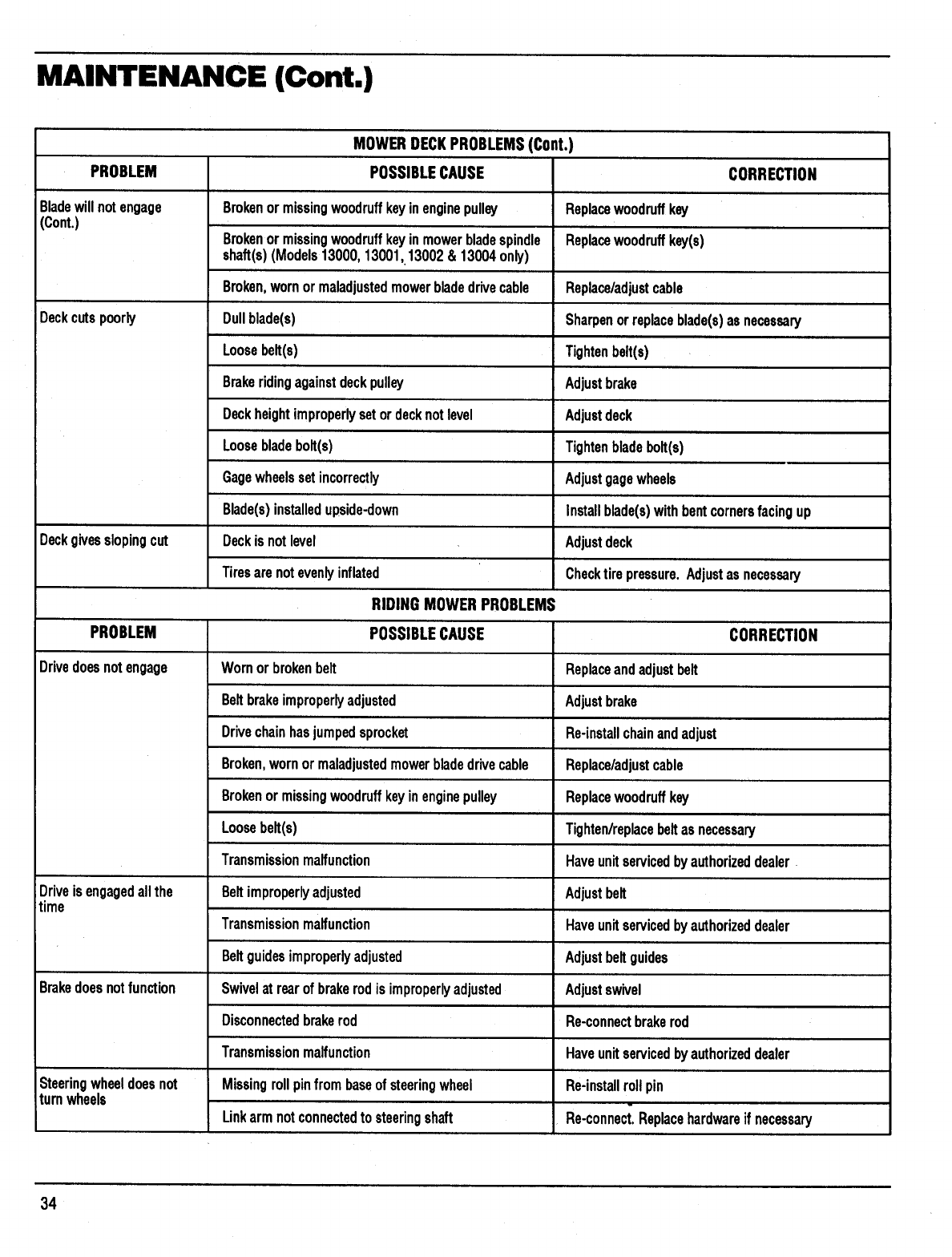
MAINTENANCE (Cont.)
PROBLEM
Bladewillnotengage
(Cont.)
Deckcutspoorly
Deckgivesslopingcut
PROBLEM
Drivedoesnotengage
Driveisengagedallthe
time
Brakedoesnotfunction
Steeringwheeldoesnot
turnwheels
MOWERDECKPROBLEMS(Cont.)
POSSIBLECAUSE
Brokenormissingwoodruffkeyinenginepulley
Brokenormissingwoodruffkeyinmowerbladespindle
shaft(s)(Models13000,13001,13002& 13004only)
Broken,wornormaladjustedmowerbladedrivecable
Dullblade(s)
Loosebelt(s)
Brakeridingagainstdeckpulley
Deckheightimproperlysetordecknotlevel
Loosebladebolt(s)
Gagewheelssetincorrectly
Blade(s)installedupside-down
Deckisnotlevel
Tiresarenotevenlyinflated
RIDINGMOWERPROBLEMS
POSSIBLECAUSE
Wornorbrokenbelt
Beltbrakeimproperlyadjusted
Drivechainhasjumpedsprocket
Broken,wornormaladjustedmowerbladedrivecable
Brokenormissingwoodruffkeyinenginepulley
Loosebelt(s)
Transmissionmalfunction
Beltimproperlyadjusted
Transmissionmalfunction
Beltguidesimproperlyadjusted
Swivelat rearofbrakerodis improperlyadjusted
Disconnectedbrakerod
Transmissionmalfunction
Missingrollpinfrom baseofsteeringwheel
Linkarmnotconnectedtosteeringshaft
Replacewoodruffkey
Replacewoodruffkey(s)
CORRECTION
Replace/adjustcable
Sharpenorreplaceblade(s)asnecessary
Tightenbelt(s)
Adjustbrake
Adjustdeck
Tightenbladebolt(s)
Adjustgagewheels
Installblade(s)withbentcornersfacingup
Adjustdeck
Checktirepressure.Adjustasnecessary
CORRECTION
Replaceandadjustbelt
Adjustbrake
Re-installchainandadjust
Replace/adjustcable
Replacewoodruffkey
Tighten/replacebeltasnecessary
Haveunitservicedbyauthorizeddealer.
Adjustbelt
Haveunitservicedbyauthorizeddealer
Adjustbeltguides
Adjustswivel
Re-connectbrakerod
Haveunitservicedbyauthorizeddealer
Re-installrollpin
Re-connect.Replacehardwareif necessary
34
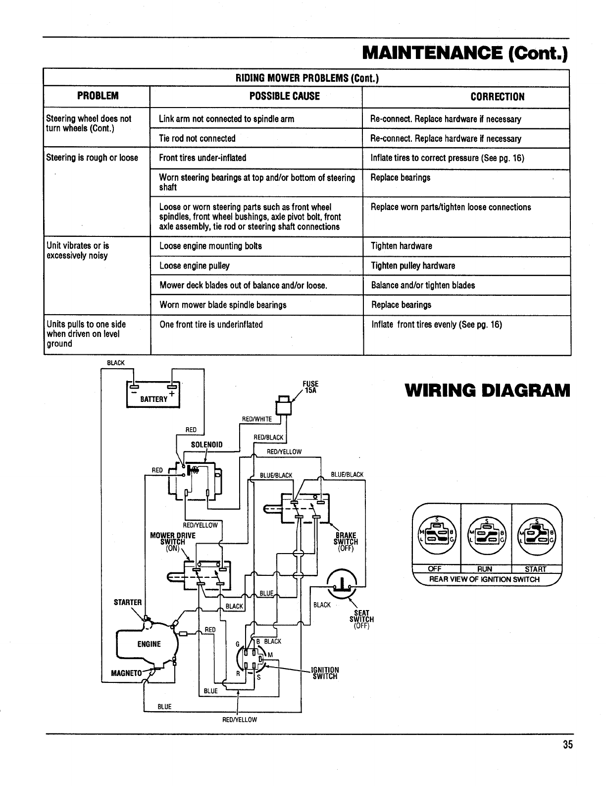
PROBLEM
Steeringwheeldoesnot
turnwheels(Cont,)
MAINTENANCE (Cont.)
RIDINGMOWERPROBLEMS(Cont.)
CORRECTION
Re-connect.Replacehardwareif necessary
Re-connect.Replacehardwareif necessary
Inflatetiresto correctpressure(Seepg.16)
Replacebearings
POSSIBLECAUSE
link armnotconnectedto spindlearm
Tierodnotconnected
Fronttiresunder-inflated
Wornsteeringbearingsattopand/orbottomofsteering
shaft
Looseorwornsteeringpartssuchasfrontwheel
spindles,frontwheelbushings,axlepivotbolt,front
axleassembly,tierodorsteeringshaftconnections
Looseenginemountingbolts
Looseenginepulley
Mowerdeckbladesoutofbalanceand/orloose.
Wornmowerbladespindlebearings
Onefronttireisunderinflated
Steeringisroughorloose
Replacewornparts/tightenlooseconnections
Unitvibratesoris Tightenhardware
excessivelynoisy Tightenpulleyhardware
Balanceand/ortightenblades
Replacebearings
Unitspullsto oneside Inflatefronttiresevenly(Seepg.16)
whendrivenonlevel
ground
BLACK
,FUSE
15A
LL = __.._ BLUE/BLACK
REDHELLOW
MOWERDRIVE
SWITCH
STARTER
BRAKE
SWITCH
(OFF)
SEAT
SWITCH
(OFF)
WIRING DIAGRAM
RUNOFF START
REAR VIEW OF IGNITION SWITCH j
;NITION
SWITCH
BLUE
RED/YELL0W
35
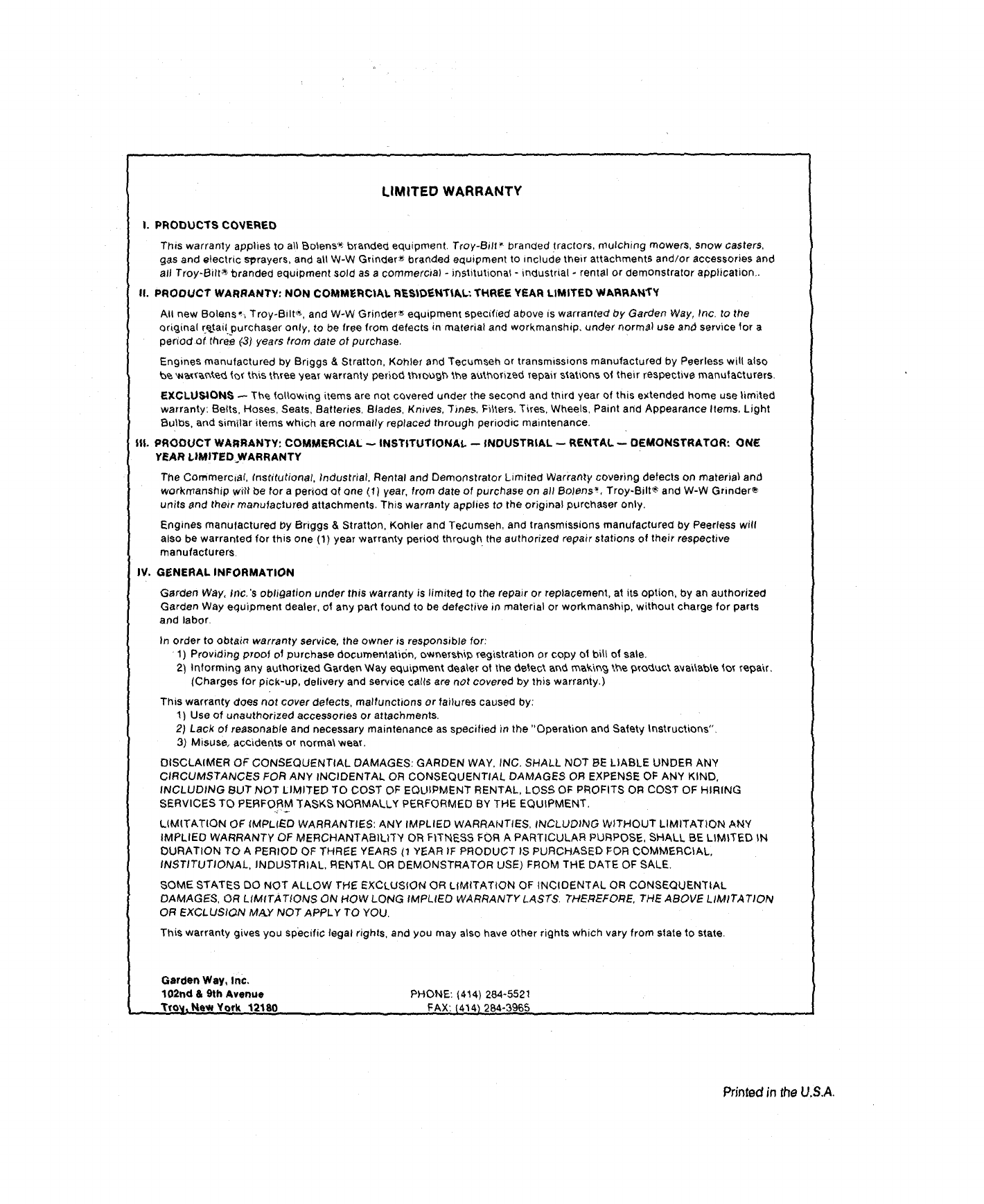
LIMITED WARRANTY
I. PRDDUCTS CDVERED
This warranty applies tO all Bolens'_ brandeq, equLpment. Troy-Bill _ branded tractors, mulching mowers, snow casters,
gas and electric sprayers, and all W-W Grinder*o branded eclu_pment to include their attachments and/or accessories and
all Troy-Bilt_ branded equipment sold as a commercial - instttutlonal - m_lustrial °rental or demonstrator application..
II. PRODUCT WARRANTY: NON COMMERCIAL RESlDEHTIAL; THREE YEAR LIMITED WARRANTY
All new Bolens,, Troy-Bilt_'_. and W-W Grinder_ equipment specified a_ove is warranted by Garden Way, Inc. to the
original [e,.ta=[purchaser only, to be free from defects in material and workmanship, under normS) use and service for a
period of three (-3) years from date of purchase.
Engines manufactured by Briggs & Stratton. Koh}e[ and Tecumsen or transmissions manufactured by Peerless will also
b,_'_te_ f_ th_s t_ree year warranty pedo_, _._o_9_ _,e a_t_,orize_ Tepa_t stations of their respective manufacturers.
EXCLU,_IDN_ _ The 1ollowing items are not covered under the second and third year of this extended home use limited
warranty: Belts. Hoses. Seats. Batteries. Blades. Knives. Tines. Fibers, Tires, Wheels, Paint and Appearance Items, Light
Bulbs. and similar items which are normally replaced through penod=c maintenance.
IlL PRODUCT WARRANTY: COMMERCIAL -- INSTITUTIONAl. -- INDUSTRIAL _ RENTAL _ DEMONSTRATOR: ONE:
YEAR L|MITED WARRANTY
The Commercial, Institutional, Industrial Rental and Demonstrator Limited Warranty covering defects on material an_
workmanship w_tt be for a period of one !f) year. from date of purchase on all BoJens_, Troy-Bilt_ and W-W Grinder_
units and thetr manufactured attachments. This warranty applies to the original purchaser only.
Engines manufactured Dy Briggs & Stratton. Kohler and Tecumsel_, and transmissions manufactured by Peerless will
also be warranted for thiS one (1) year warranty perlo_l througr_ the authorized repair stations of their respective
manufacturers.
IV. GENERAL INFORMATION
Garden Way, Inc. 's obligation under this warranty is limited to the repair or replacement, at its option, by an authorized
Garden Way equipment dealer, of any part found to be defective in material or workmanship, without charge for parts
and labor.
In order to obtain warranty service, the owner is responsible for:
•1) Providing proof of purchase documentati6n, o_ner_hi1_ _'egi,stration or copy ot bill of sale.
2) Informing any authorized Garden Way equipment dealer ot the de_ec _, an_ m_,_g t_,e 9rO_,_ct aY_\&b_ lot r_,a_r.
(Charges for pick-up, delivery and service carts are not covered by this warranty.)
This warranty does not cover defects, malfunctions or failures caused by:
1) Use of unauthorized accessories or attachments.
2) Lack of re,_sonable and necessary maintenance as specified in the "Operation and Safety Instructions".
3) Misuse, accidents or norma\ wear.
DISCLAIMER OF CONSEQUENTIAL DAMAGES: GARDEN WAY, INC. SHALL NOT BE LIABLE UNDER ANY
CIRCUMSTANCF.S FOR ANY INCIDENTAL OR CONSEQUENTIAL DAMAGES OR EXPENSE OF ANY KIND,
INCLUDING BUT NOT LIMITED TO COST OF EQUIPMENT RENTAL, LOSS OF PROFITS OR COST OF HIRING
SERVICES TO PERFORM ]'ASKS NORMALLY PERFORMED BY THE EQUIPMENT.
LIMITATION OF IMPLIED WARRANTIES: ANY IMPLIED WARRANTIES, INCLUDING WITHOUT LIMITATION ANY
IMPLIED WARRANTY OF MERCHANTABILITY OR FITNESS FOR A PARTICULAR PURPOSE, SHALL BE LIMITED IN
DURATION TO A PERIOD OF THREE YEARS (1 YEAR IF PRODUCT IS PURCHASED FOR COMMERCIAL,
INSTITUTIONAL, INDUSTRIAL, RENTAL (DR DEMONSTRATOR USE) FROM THE DATE OF SALE.
SOME STATES DO NOT ALLOW THE EXCLUSION OR LIMITATION OF INCIDENTAL OR CONSEQUENTIAL
DAMAGES, OR L_MITATIONS ON HOW LONG IMPLIED WARRANTY LASTS. THEREFORE, THE ABOVE LIMITATION
OR EXCLUSION M,tO "NOT APPLY TO YOU.
This warranty gives you specific legal rights, and you may also have other rights which vary from state to state.
Garden Way, Inc,
102nd & 9th Avenue
_- "