BRAINTECH FM1000MF COMMERCIAL User Manual FM1000UserManual
BRAINTECH CO., LTD COMMERCIAL FM1000UserManual
UserManual.wiki
>
BRAINTECH
>
FM1000MF User Manual
USERS MANUAL
Navigation menu
Upload a User Manual
Namespaces
Wiki Guide
HTML
PDF
Info
Views
User Manual
Discussion / Help
Navigation
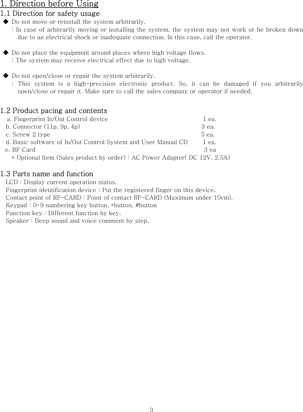
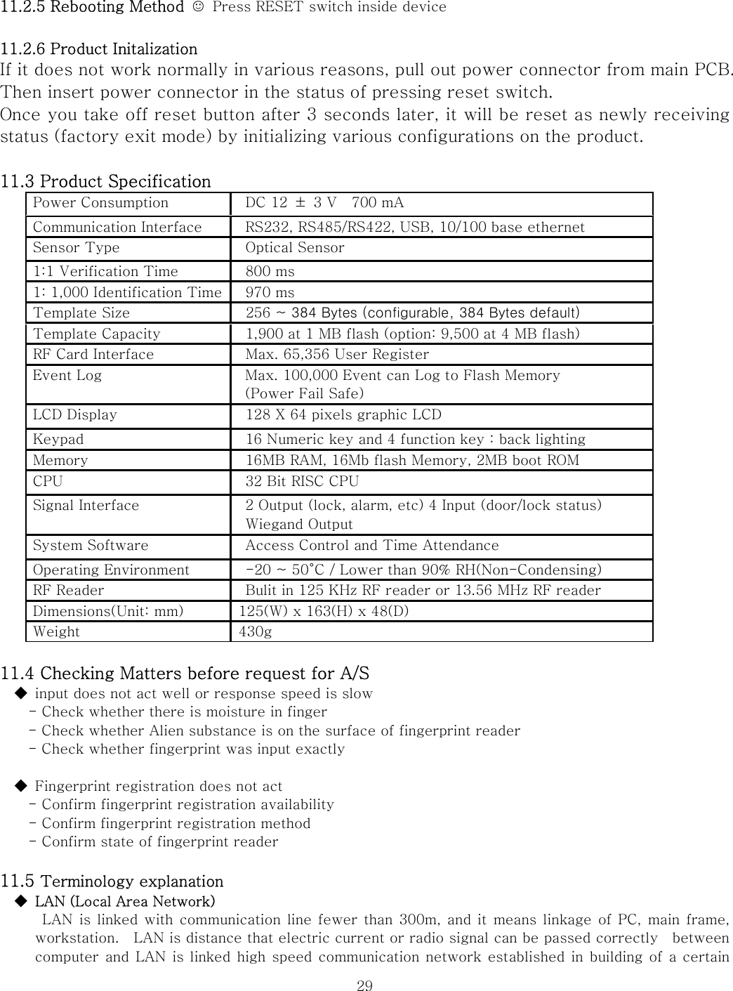
![5 previous screen and selecting the attendance mode. F2 button The button is used when selecting the leaving office mode. F3 button The button is used when selecting the go out mode. F4 button The button is used when selecting the return office, manager mode and menu. 1.5 Fingerprint identification process Picture 1 Picture 2 ☺ Finger should be kept clean, so that a correct recognition is possible. ☺ If the finger is wet, recognition may be impossible. ☺ Make sure that there is no alien substance on the fingerprint recognizer. ☺ Place the finger correctly at the center of the fingerprint recognizer as shown in <Picture 1>. ☺ All fingerprint should be touching the fingerprint recognizer as shown in <Picture 2>. 2. Manager Registration ☺ The manager password is not registered when you open the package box and operate the product for the first time. No Register Master Password Please type Password [ ] [ ] * Back # NEXT F1 Cancel F4 Ok 1. When the power is on for the first time, a window for setting the manager password will pop up as shown in the left screen. No Register Master Password Please type Password [***** ] [ ] * Back # NEXT F1 Cancel F4 Ok 2. Use the number buttons to enter the manager password (above 5 figures) and press the # button. ◆ If you entered the wrong number! * Press the button and reenter the number. No Register Master Password Please type Password [***** ] [***** ] 3. Enter the same password (above 5 figures) in the below blank and save it by pressing F4. ◆ Precautions! If you fail to enter the password with the given time, the screen goes back to its](https://usermanual.wiki/BRAINTECH/FM1000MF/User-Guide-964844-Page-5.png)
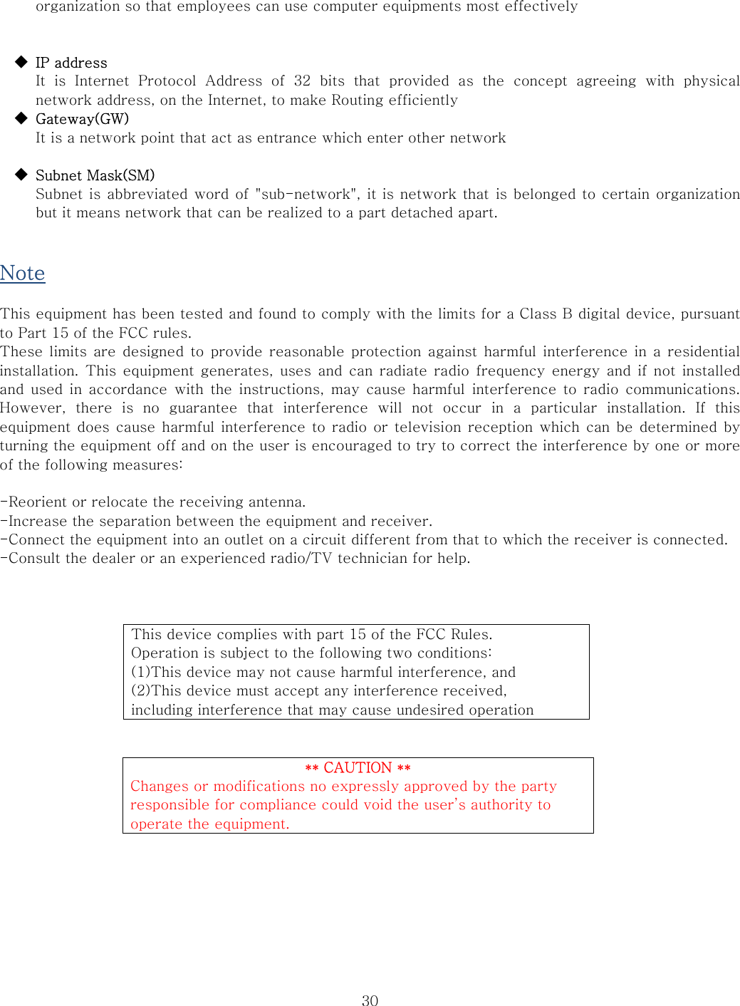
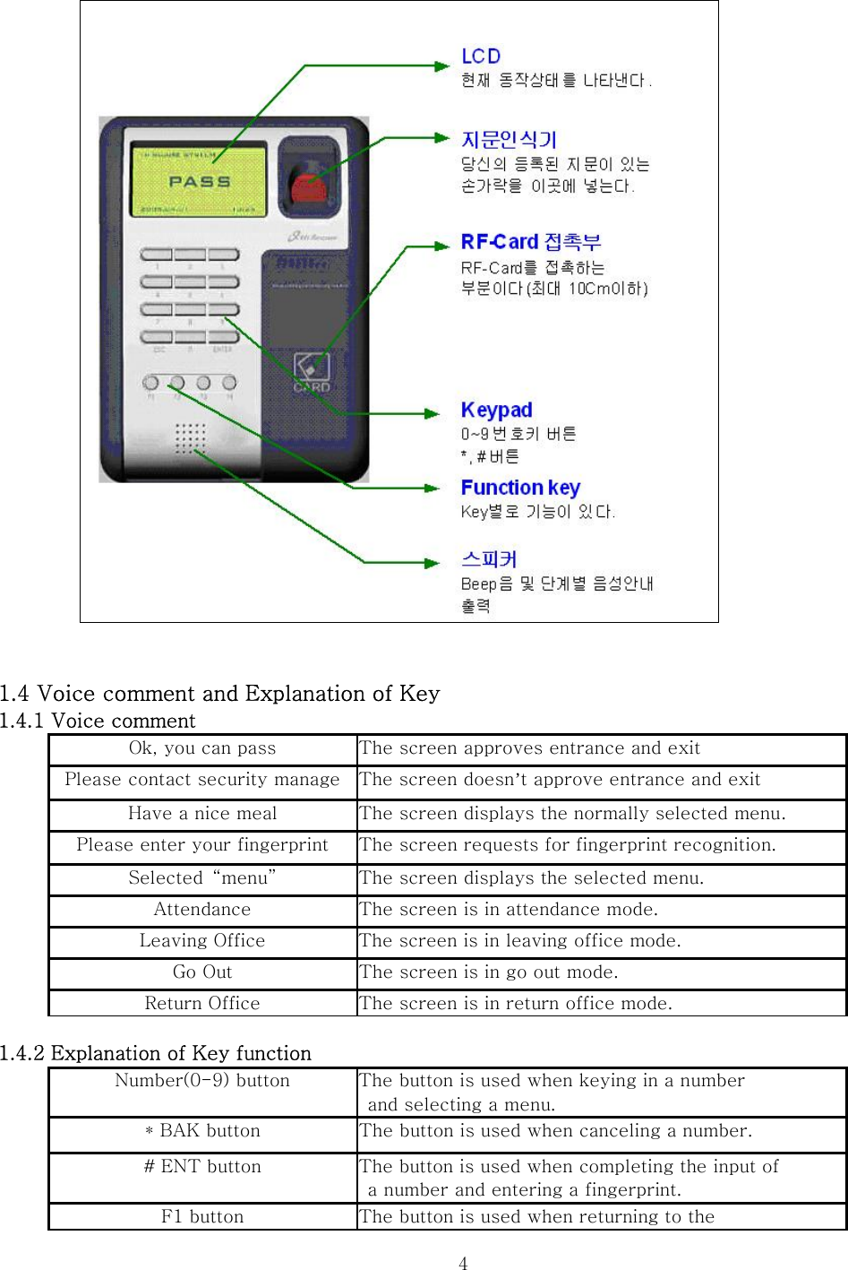
![6* Back # NEXT F1 Cancel F4 Ok original state. OK !!! Master Password Registered 4. After successfully registering the manager password, the left-sided screen appears. Password Length Less than 5 Please try again 5. If you enter a password (below 5 figures), the left-sided screen appears. In this case, please reenter your password (above 5 figures). 3. Manager Menu Calling ☺ Press F4 to enter into the manager menu. 1. Controller Setup: Control the equipment setup. 2. User Management: Add/delete the user or manage the entrance/exit. 3. DB Management: Manage the equipment data base. 4. Password change: Change the manager password. 5. Door Operation: Setup the door operation method. * Manager Menu Calling MAIN Menu 1. Controller Setup 2. User Management 3. DB Management 4. Passwd change 5. Door Operation F1 Cancel F4 OK 1. Enter into the Controller Setup menu by pressing the number key, ‘1’ from the manager menu window on the left. Controller Setup 1. Date/Time 2. Network Setup 3. Manage Mode 4. ETC Setup 5. Door Setup F1 Cancel F4 OK 2. Select the date and time setup items by pressing the number key, ‘1’ from the Controller Setup menu. Date/Time Setting Year Month Day [_ ] [ ] [ ] Hour Minute Second [ ] [ ] [ ] * Back # Next F1 Cancel F4 OK 3. You can see a window for setting up the year, date, hour, minute and second as shown in the left-side picture. Date/Time Setting Year Month Day [2006] [_ ] [ ] Hour Minute Second [ ] [ ] [ ] * Back # Next F1 Cancel F4 OK 4. Enter the year by using a number button. After the 4 figures are entered, the cursor automatically moves to the month blank. Date/Time Setting Year Month Day [2006] [_ ] [ ] 5. Enter the month by using a number key. After entering the month (1 figure), press the # button to move the cursor to the date blank.](https://usermanual.wiki/BRAINTECH/FM1000MF/User-Guide-964844-Page-6.png)
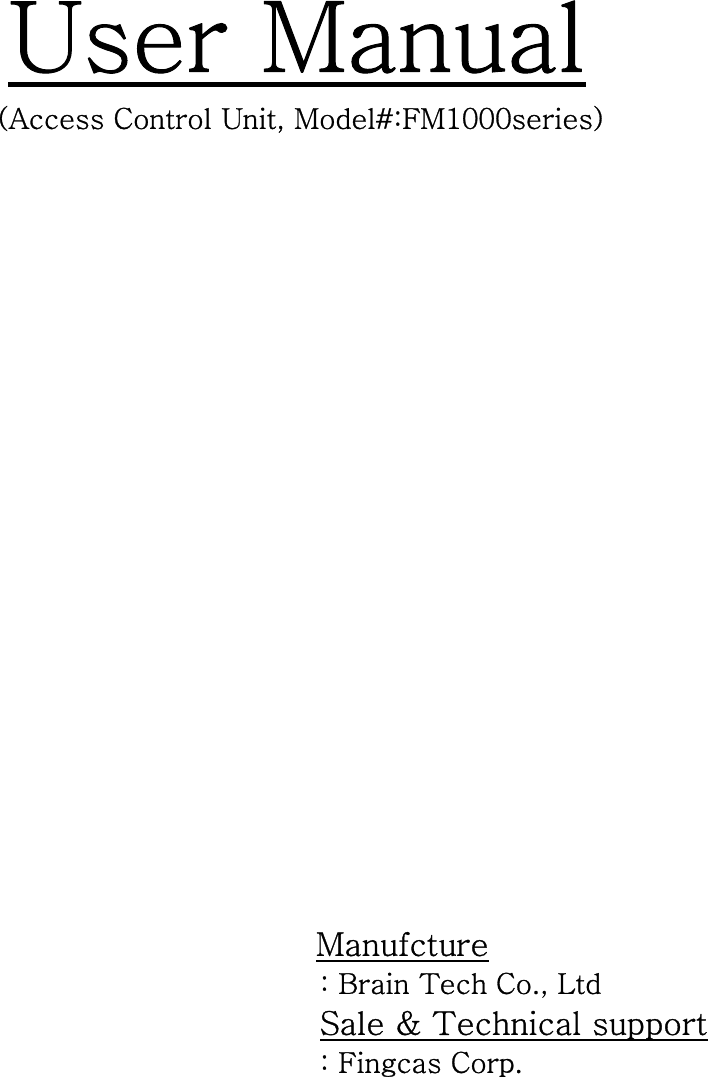
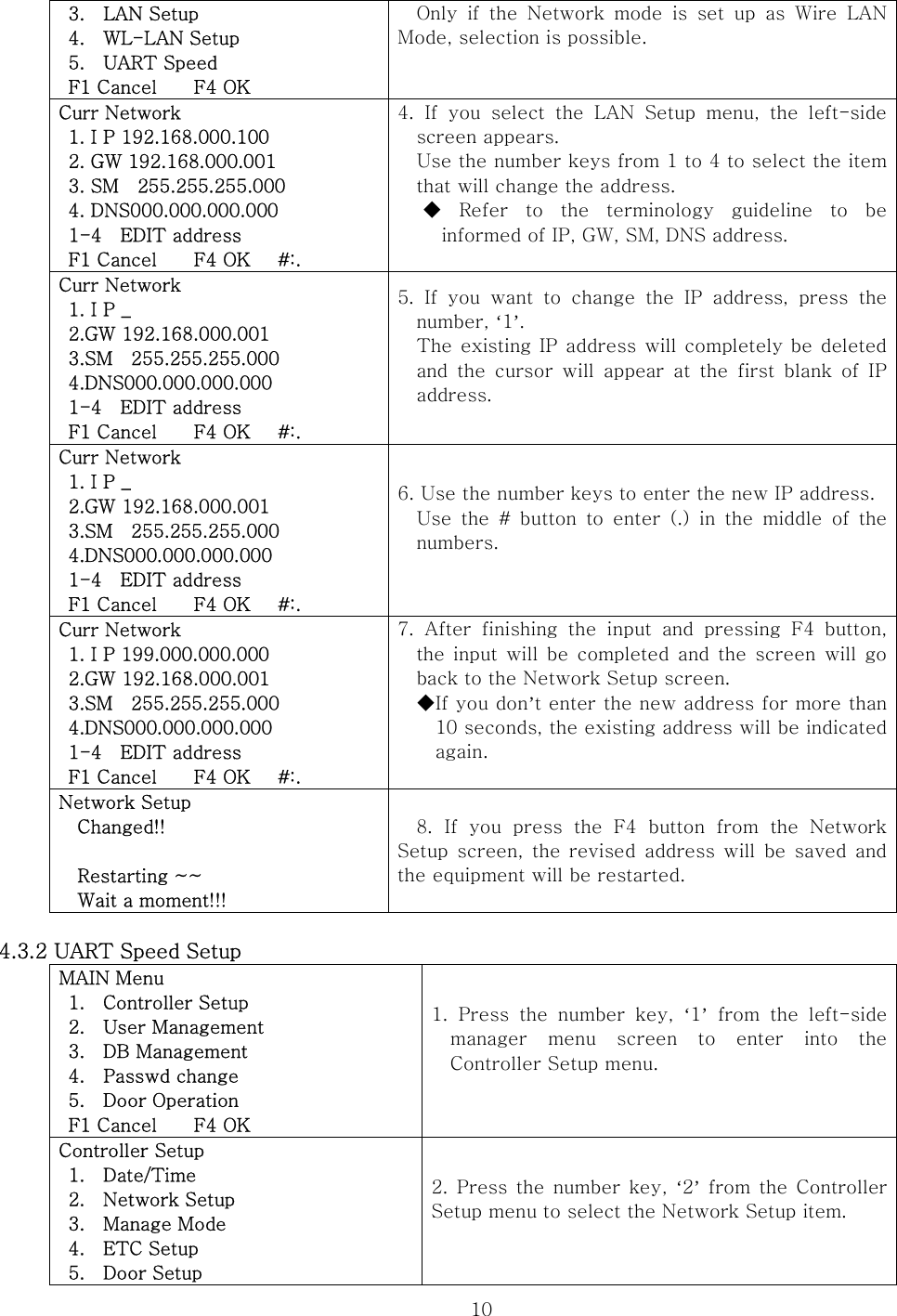
![7 Hour Minute Second [ ] [ ] [ ] * Back # Next F1 Cancel F4 OK ◆ If you entered the wrong number! * Press the button and reenter the number. Date/Time Setting Year Month Day [2006] [10] [20] Hour Minute Second [12] [10] [35] * Back # Next F1 Cancel F4 OK 6. After entering both the date and time, press the F4 button to save the registered date and time. 4. Controller setup 4.1 Date and Time Setup ◆ Example of Date and Time Setup(Enter 9 o‘clock 37 min. 52 sec. on October 8th 2006) 1. Press F4 for a few seconds from the initial window and enter the manager password to call the manager menu. 2. Press the number key, ‘1’ two times from the manager menu screen to enter into the date and time setup menu. 3. If you press the number keys, ‘2, 0, 0, 6’, the year will be entered. Then, the cursor will automatically move to the month blank. 4. If you press the number keys, ‘1, 0’, the month will be entered. Then, the cursor will automatically move to the date blank. 5. If you press the number key, ‘8’ to enter the date and press the # button, the cursor will move to the time blank. 6. If you press the number key, ‘9’ to enter the time and press the # button, the cursor will move to the minute blank. 7. After pressing the number keys, ‘3, 7’ to enter the minute, the cursor will automatically move to the second blank. 8. After pressing the number keys, ‘5, 2’ to enter the seconds, the date and time setup will be finished and the screen will return to the Controller Setup Screen. 9. If the second is one figure, press the number and # or F4 button to complete the input. 4.2 ACU Number Setup MAIN Menu 1. Controller Setup 2. User Management 3. DB Management 4. Passwd change 5. Door Operation F1 Cancel F4 OK 1. Press the number key, ‘1’ from the manager menu screen on the left to enter into the Controller Setup menu. Controller Setup 1. Date/Time 2. Network Setup 3. Manage Mode 4. ETC Setup 5. Door Setup 2. Press the number key, ‘2’ from the Controller Setup menu to select the Network Setup item.](https://usermanual.wiki/BRAINTECH/FM1000MF/User-Guide-964844-Page-7.png)
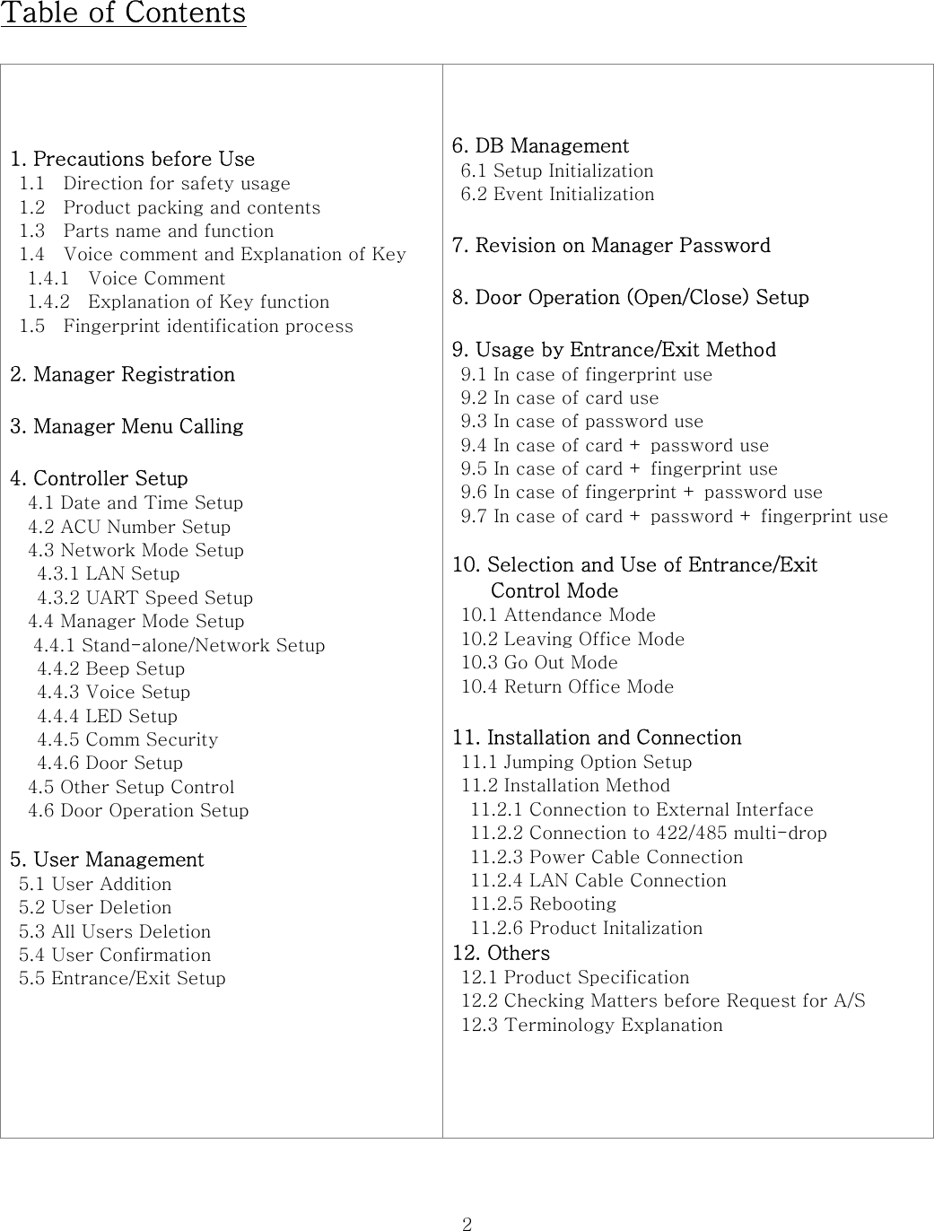
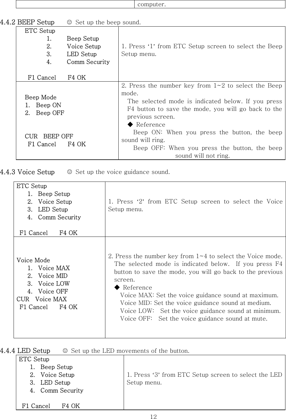
![8 F1 Cancel F4 OK Network Setup 1. ACU Number 2. Network Mode 3. LAN Setup 4. WL-LAN Setup 5. UART Speed F1 Cancel F4 OK 3. Press the number key, ‘1’ from the Network Setup menu to select the ACU Number item. ACU Number Curr [001] New [_ ] * Back # OK F1 Cancel F4 OK 4. You can see the ACU Number setup screen. Curr indicates the ACU Number that is currently setup. ACU Number Curr [001] New [255] * Back # OK F1 Cancel F4 OK 5. Use the number keys to enter the ACU Number (3 figures) in the New blank. You can enter a number within the range from 001 to 255. Invalid ACU Number Please try again 6. If you enter a number out of the range from 001 to 255, The left-side error screen will appear and go back to the ACU Number setup screen. OK ACU Number Successfully Changed 7. If you entered a number within the range of 001 to 255, you can confirm the successfully revised ACU Number from the left-side screen. Network Setup 1. ACU Number 2. Network Mode 3. LAN Setup 4. WL-LAN Setup 5. UART Speed F1 Cancel F4 OK 8. After the ACU Number is entered, the screen goes back to the Network Setup Screen. If you press F4 from the left-side screen, the ACU Number will be revised. Network Setup Changed!! Restarting ~~ Wait a moment!!! 9. If you press the F4 button, the left-side screen will appear and the equipment will restart to revise the Network setup. 4.3 Network Mode 설정 MAIN Menu 1. Controller Setup 2. User Management 3. DB Management 4. Passwd change 5. Door Operation F1 Cancel F4 OK 1. Press the number key, ‘1’ from the left-side manager menu screen to enter into the Controller Setup menu. Controller Setup 2. Press the number key, ‘2’ from the Controller](https://usermanual.wiki/BRAINTECH/FM1000MF/User-Guide-964844-Page-8.png)
![9 1. Date/Time 2. Network Setup 3. Manage Mode 4. ETC Setup 5. Door Setup F1 Cancel F4 OK Setup menu to select the Network Setup item. Network Setup 1. ACU Number 2. Network Mode 3. LAN Setup 4. WL-LAN Setup 5. UART Speed F1 Cancel F4 OK 3. Press the number key, ‘2’ from the Network Setup menu to select the Network Mode item. NET MODE 1. No LAN 2. Wire LAN MODE 3. WL-LAN infrastruct 4. WL-LAN Ad-hoc [No LAN] F1 Cancel F4 OK 4. The screen for setting up the network mode appears. You can select the mode you want by using the number key. The selected mode is indicated below. NET MODE 1. No LAN 2. Wire LAN MODE 3. WL-LAN infrastruct 4. WL-LAN Ad-hoc [Wire LAN] F1 Cancel F4 OK 5. After pressing the number keys to select the Network Mode you want and pressing F4 button, the Network Mode will be saved and the screen will go back to the Network Setup screen. Refer to the terminology guideline to be informed of the Network Mode. Network Setup Changed!! Restarting ~~ Wait a moment!!! 6. If you press F4 button from the Network Setup screen, the left-side screen appears and the equipment will restart. 4.3.1 LAN Setup MAIN Menu 1. Controller Setup 2. User Management 3. DB Management 4. Passwd change 5. Door Operation F1 Cancel F4 OK 1. Press the number key, ‘1’ from the left-side manager menu screen to enter into the Controller Setup menu. Controller Setup 1. Date/Time 2. Network Setup 3. Manage Mode 4. ETC Setup 5. Door Setup F1 Cancel F4 OK 2. Press the number key, ‘2’ from the Controller Setup menu to select the Network Setup item. Network Setup 1. ACU Number 2. Network Mode 3. Press the number key, ‘3’ from the Network Setup menu to select the LAN Setup item. ◆Precautions!](https://usermanual.wiki/BRAINTECH/FM1000MF/User-Guide-964844-Page-9.png)
![11 F1 Cancel F4 OK Network Setup 1. ACU Number 2. Network Mode 3. LAN Setup 4. WL-LAN Setup 5. UART Speed F1 Cancel F4 OK 3. Press ‘5’ from the Network Setup menu to select the UART Speed item. ◆ Refer to the terminology guideline to be informed of UART in detail. UART Speed Change CUR : 57600 1.1200 6.28800 2.2400 7.38400 3.4800 8.57600 4.9600 9.115200 5.19200 0.230400 4. A screen for setting up UART Speed appears. The number next to CUR indicates the currently registered UART Speed. You can select the speed you want by using the number key. Network Setup 1. ACU Number 2. Network Mode 3. LAN Setup 4. WL-LAN Setup 5. UART Speed F1 Cancel F4 OK 5. If you select the UART Speed, you will go back to the previous screen as shown on the left. If you press F4 to save UART Speed, the setup of UART Speed will be completed. Network Setup Changed!! Restarting ~~ Wait a moment!!! 6. If you press F4 to save the revised UART Speed, the equipment will restart to apply the revised setup. 4.4 Manager Mode Setup 4.4.1 Network/Stand-alone setup MAIN Menu 1. Controller Setup 2. User Management 3. DB Management 4. Passwd change 5. Door Operation F1 Cancel F4 OK 1. Press the number key, ‘1’ from the left-side manager menu screen to enter into Controller Setup menu. Controller Setup 1. Date/Time 2. Network Setup 3. Manage Mode 4. ETC Setup 5. Door Setup F1 Cancel F4 OK 2. Press the number key, ‘3’ from Controller Setup menu to select the Manage Mode item. Manage Mode 1. Stand-alone 2. Network Only [Stand-alone ] F1 Cancel F4 OK 3. Press the number key to set up the Manage Mode. The selected Manage Mode is indicated below. Press F4 to save the Manage Mode. ◆ Reference Stand-alone: Setting with a stand-alone menuNetwork Only: Setting into a manage](https://usermanual.wiki/BRAINTECH/FM1000MF/User-Guide-964844-Page-11.png)
![13LED Mode 1. Always OFF 2. ON at KEY 3. Always ON CUR ON at KEY F1 Cancel F4 OK 2. Press the number key from 1~3 to select the LED mode. The selected mode is indicated below. If you press F4 button to save the mode, you will go back to the previous screen. ◆ Reference Always OFF: The button LED will always be turned on. ON at KEY: LED will be turned on whenever you press the button. Always ON: LED is always turned on. 4.4.5 Comm Security ☺ Set up the computer security. ETC Setup 1. Beep Setup 2. Voice Setup 3. LED Setup 4. Comm Security F1 Cancel F4 OK 1. Press ‘4’ from ETC Setup screen to select the Comm Security menu. 1) FTP/TELNET ON/OFF: Set up FTP/TELNET. 2) Packet Encryption: Set up the packet password. 3) Encryption ON/OFF: Turn on/off the packet password. COMM Security 1. FTP/TELNET ON/OFF 2. Packet Encryption 3. Encryption ON/OFF F1 Cancel F4 OK 2. Press the number key from 1~3 to select the menu you want to control. FTP/TELNET ON/OFF 1. FTP/TELNET ON 2. FTP/TELNET OFF CUR FTP/TELNET ON F1 Cancel F4 OK 3. If you select FTP/TELNET item, you can see the left-side screen. After pressing the number key to set up FTP/TELNET and pressing F4, the set up will be saved and you will go back to the previous screen. ENC KEY Setup 1. KEY1 [ 0] 2. KEY2 [ 0] 3. KEY3 [ 0] F1 Cancel F4 OK 4. If you press ‘2’ from the COMM Security screen, you can see the left-side screen. You can set up the packet password or press the number key from 1~3 to select the password key you want to enter. ENC KEY Setup 1. KEY1 [_ ] 2. KEY2 [ 0] 3. KEY3 [ 0] F1 Cancel F4 OK 5. If you press ‘1’, you can enter KEY1. Use the number key to enter the 5 figure password. Then, press F4 button to save the password. You will go back to the previous screen. Encryption ON/OFF 1. Encryption ON 2. Encryption OFF CUR Encrytion OFF 6. If you press ‘3’ from the COMM Security screen, you can see the left-side screen. After pressing the number key to set up the packet password and pressing F4 button, the set up will be saved and you will go back to the previous screen.](https://usermanual.wiki/BRAINTECH/FM1000MF/User-Guide-964844-Page-13.png)
![14F1 Cancel F4 OK 4.4.6 Door Setup MAIN Menu 1. Controller Setup 2. User Management 3. DB Management 4. Passwd change 5. Door Operation F1 Cancel F4 OK 1. Press the number key, ‘1’ from the left-side manager menu screen to enter into the Controller Setup menu. Controller Setup 1. Date/Time 2. Network Setup 3. Manage Mode 4. ETC Setup 5. Door Setup F1 Cancel F4 OK 2. Press the number key, ‘5’ from the Controller Setup menu to select the Door Setup item. Door Setup Hold Time [003] Alarm Time [005] * Back # NEXT F1 Cancel F4 OK 3. You can set up the door operation. After entering the item you want and pressing F4 to save the time, you will go back to the previous screen. Time will be set up in seconds. ◆ Reference Hold Time: Meaning that the door is opened. Alarm Time: Setting up the alarm ringing time. 5. User Management 5.1 User Addition MAIN Menu 1. Controller Setup 2. User Management 3. DB Management 4. Passwd change 5. Door Operation F1 Cancel F4 OK 1. Press number key 2 in administrator menu screen as like left and enter to User Management menu. User Manager 1. Add User 2. Delete One User 3. Delete All User 4. Check User 5. Pass Method F1 Cancel F4 OK 2. Press number key 1 in User Manager menu and select Add User article](https://usermanual.wiki/BRAINTECH/FM1000MF/User-Guide-964844-Page-14.png)
![151. ID [00000] 0. [USR] 2. Passwd1 [********] 3. Passwd2 [********] 4. StartDate [061013] 5. End Date [321231] FP[N] RF[00000000] 1-5, # Finger, F4 OK ID : User ID USR/MST/SPR : User type Passwd1 : User password Passwd2 : Password re-input Start Date : Application point of user informationEnd Date : User information expiration point FP[3] : Whether or not fingerprint registration (present, 3 registered) RF[7486F23S] : Registered RF card number 1. Passwd1 [********] 2. Passwd2 [********] 3. StartDate [061013] 4. ID [_ ] 0. [USR] 5. End Date [321231] FP[N] RF[00000000] 1-5, # Finger, F4 OK 3. Can input user ID if press number key 1. Input five seat numbers using number key 1. ID [01234] 0. [USR] 2. Passwd1 [_ ] 3. Passwd2 [********] 4. StartDate [061013] 5. End Date [321231] FP[N] RF[00000000] 1-5, # Finger, F4 OK 4. Can input user password if press number key 2. If press F4, input is ended after input number fewer than 8 seats. 1. Passwd1 [********] 2. ID [01234] 0. [USR] 3. Passwd2 [_ ] 4. StartDate [061013] 5. End Date [321231] FP[N] RF[00000000] 1-5, # Finger, F4 OK 5. Presses number key 3 and re-input user password.In case of input other number different with number inputting at Passwd1, error message should be registered and input again. 1. ID [01234] 0. [USR] 2. Passwd1 [********] 3. Passwd2 [********] 4. StartDate [_ ] 5. End Date [321231] FP[N] RF[00000000] 1-5, # Finger, F4 OK 6. Can input ready time to apply user information if press number key 4. Year, end two seats – month – in order of work input Ex ) Input October 20, 2006 by 061020 1. ID [01234] 0. [USR] 2. Passwd1 [********] 3. Passwd2 [********] 4. StartDate [061020] 5. End Date [_ ] FP[N] RF[00000000] 1-5, # Finger, F4 OK 7. If press number key 5, can input point that User information is expired. Input by method such as ready time 1. ID [01234] 0. [USR] 2. Passwd1 [********] 3. Passwd2 [********] 4. StartDate [061013] 5. End Date [301201] FP[1] RF[00000000] 8. Can input fingerprint if press # button. Refer to fingerprint realization method of previous page, put fingerprint on fingerprint reader. If fingerprint was realized, character N of FP side changes by number.](https://usermanual.wiki/BRAINTECH/FM1000MF/User-Guide-964844-Page-15.png)
![161-5, # Finger, F4 OK 1. ID [01234] 0. [USR] 2. Passwd1 [********] 3. Passwd2 [********] 4. StartDate [061013] 5. End Date [321231] FP[2] RF[00000000] 1-5, # Finger, F4 OK 9. In case of input fingerprint additionally, press # button and put finger to fingerprint reader. When it is realized normally, number of FP side increases. Fingerprint can register to 10 per user. 1. ID [01234] 0. [USR] 2. Passwd1 [********] 3. Passwd2 [********] 4. StartDate [061013] 5. End Date [321231] FP[2] RF[7479F60E] 1-5, # Finger, F4 OK 10. In case of wishing to register RF card, if put close to RF card contact part of device external, RF card value is registered and registration is ended. Register User Successfully Finished 11. If press F4 button after input all user information, screen appears such as left and user information is saved. After save, screen returns by user management menu 5.2 User Deletion MAIN Menu 1. Controller Setup 2. User Management 3. DB Management 4. Passwd change 5. Door Operation F1 Cancel F4 OK 1. In administrator menu screen such as left, press number key 2 and enter to User Management menu User Manager 1. Add User 2. Delete One User 3. Delete All User 4. Check User 5. Pass Method F1 Cancel F4 OK 2. Press 2 in User Manager menu and select Delete One User article USER-ID [. . . . .] Date . . . . . . - . . . . . . FP[ . ] RF [. . . . . . . .] 0-9 search by ID F1 Cancel F3 Delete F4 OK 3. If input user ID to delete by using number key, user information appears and if press F3, relevant user information is deleted. Can return to previous screen if press F1 or F4 5.3 All Users Deletion MAIN Menu 1. Controller Setup 2. User Management 3. DB Management 1. press number key 2 in administrator menu screen such as left and enter to User Management menu.](https://usermanual.wiki/BRAINTECH/FM1000MF/User-Guide-964844-Page-16.png)
![17 4. Passwd change 5. Door Operation F1 Cancel F4 OK User Manager 1. Add User 2. Delete One User 3. Delete All User 4. Check User 5. Pass Method F1 Cancel F4 OK 2. press 3 in User Manager menu and select Delete All User article. Delete All User 1. Yes 2. No 3. All user information are deleted if press 1 and message "All User Deleted" is registered and return by previous screen. If press 2 "Delete" is cancelled and returns to previous screen. 5.4 User confirmation MAIN Menu 1. Controller Setup 2. User Management 3. DB Management 4. Passwd change 5. Door Operation F1 Cancel F4 OK 1. press number key 2 in administrator menu screen such as left and enter to User Management menu User Manager 1. Add User 2. Delete One User 3. Delete All User 4. Check User 5. Pass Method F1 Cancel F4 OK 2. Press 4 in User Manager menu and select Check User article USER-ID [. . . . .] Date . . . . . . - . . . . . . FP[ . ] RF [. . . . . . . .] 0-9 : search by ID # search by Finger RF search by Card F1 Cancel F4 OK 3. If input user ID using number key, relevant user's information is registered. If press # button, can confirm user with fingerprint, and if contact RF card, it is possible also to confirm by card. Can return to previous screen if press F1 or F4. 5.5 Entrance/Exit Setup MAIN Menu 1. Controller Setup 2. User Management 3. DB Management 4. Passwd change 5. Door Operation F1 Cancel F4 OK 1. Press number key 2 in administrator menu screen such as left and enter to User Management menu](https://usermanual.wiki/BRAINTECH/FM1000MF/User-Guide-964844-Page-17.png)
![18User Manager 1. Add User 2. Delete One User 3. Delete All User 4. Check User 5. Pass Method F1 Cancel F4 OK 2. Press 5 in User Manager menu and select Pass Method article 1. Method for USER 2. Group [ 1 ] Single 3. PIN Only [ * ] 4. Card Only [ * ] 5. Finger Only [ * ] Press 1-5 for toggle F1 Cancel F4 OK 3. Can make toggle each article by pressing 1~5. If press 1, can change group to setup exit and entrance method. It will be changed in order of User – Master – Super 1. Method for USER 2. Group [ 1 ] Single 3. PIN Only [ * ] 4. Card Only [ * ] 5. Finger Only [ * ] Press 1-5 for toggle F1 Cancel F4 OK 4. If press 2, can set exit and entrance method of selected group. It will be changed in order of Single – Dual – Triple. Can set up to 1~3 the element needed in exit and entrance approval. 1. Method for USER 2. Group [ 1 ] Single 3. PIN Only [ * ] 4. Card Only [ * ] 5. Finger Only [ * ] Press 1-5 for toggle F1 Cancel F4 OK 5. Can set available exit and entrance method by pressing 3~5. * is registered to available method. ◆ PIN : Exit and entrance by ID and password Card : Exit and entrance by RF card Finger : Exit and entrance with registered fingerprint 1. Method for USER 2. Group [ 1 ] Single 3. PIN Only [ * ] 4. Card Only [ * ] 5. Finger Only [ * ] Press 1-5 for toggle F1 Cancel F4 OK 6. After completion of setting, press F4 button to save setting and to return to previous screen. ◆◆(Illustration of exit and entrance method setting ) User group can set to exit and enter by using fingerprint and password, RF card and fingerprint. 1. Method for USER 2. Group [ 1 ] Single 3. PIN Only [ * ] 4. Card Only [ * ] 5. Finger Only [ * ] Press 1-5 for toggle F1 Cancel F4 OK 1. Press 1 in exit and entrance method setting screen after select group by user, and change exit and entrance method from Single to Dual by pressing 2. 1. Method for USER 2. Group [ 2 ] Dual 3. CARD + PIN [ * ] 4. CARD + Finger [ * ] 5. Finger + PIN [ * ] Press 1-5 for toggle 2. Cancel selection of CARD + PIN item by pressing 3. User group is set to take in and out only using RF card and fingerprint or fingerprint and password.](https://usermanual.wiki/BRAINTECH/FM1000MF/User-Guide-964844-Page-18.png)
![19F1 Cancel F4 OK 1. Method for USER 2. Group [ 2 ] Dual 3. CARD + PIN [ ] 4. CARD + Finger [ * ] 5. Finger + PIN [ * ] Press 1-5 for toggle F1 Cancel F4 OK 3. Can return to previous screen if save pressing F4 button after completion set. User group can take in and out by Card and fingerprint, fingerprint and password. Please Touch Finger 4. After changing method taking in and out, it is available to take in and out only by chamged method. Can see screen that requires fingerprint input as like left if contact RF card in initial screen 14 Oct 2006 21:37:44 Thank You 5. When input right fingerprint, screens such as left is registered and "Ok You can pass" opens door with guidance sound 14 Oct 2006 21:37:44 No Trespassing 6. Screen such as left is registered in case of input wrong fingerprint or do not input fingerprint within 5 seconds saying guidance sound of "Please Contact your security Manager" Please Touch Finger 7. Taking in and out is possible by fingerprint and password. Screen such as left is registered if # press button and input fingerprint to fingerprint reader that has registered beforehand. Need Password check [_ ] * Back # Next F1 Cancel F4 OK 8. Can input password after input fingerprint. If input correctly set password and press F4, then the door opens ◆Caution !!! Registered exit and entrance method should be enforced sequentially . !!! Ex) In case of selection Card + PIN to Dual menu, must input password after RF card contact, and can not take in or out in case of input first password. In case set Triple menu, according to order input of RF card contact password input fingerprint 6. DB Management 6.1 Setup Initialization MAIN Menu 1. Controller Setup 2. User Management 3. DB Management 4. Passwd change 5. Door Operation F1 Cancel F4 OK 1. In administrator menu screen such as left press number key 3 and enter to DB Management menu. DB Management 1. Init config 2. Database management screen appears as like left. Press 1 for setting initialization and select Init Config](https://usermanual.wiki/BRAINTECH/FM1000MF/User-Guide-964844-Page-19.png)
![202. Init Event F1 Cancel F4 OK article Init Config 1. Yes 2. No 3. Device setting is initialized if press 1 in left screen and returns to previous screen. Can return to previous screen without initializing setting if press 2. 6.2 Event Initialization MAIN Menu 1. Controller Setup 2. User Management 3. DB Management 4. Passwd change 5. Door Operation F1 Cancel F4 OK 1. In administrator menu screen such as left, press number key 3 and enter to DB Management menu. DB Management 1. Init config 2. Init Event F1 Cancel F4 OK 2. Database management screen appears as like left. Press 2 and select Init Event article Init Event 1. Yes 2. No 3. if press 1 in left screen, event is initialized and returns to previous screen. Can return to previous screen without initializing setting if press 2. 7. Revision of Manager Password MAIN Menu 1. Controller Setup 2. User Management 3. DB Management 4. Passwd change 5. Door Operation F1 Cancel F4 OK 1. Press number key 4 in administrator menu screen such as left and enter to Passwd change menu Change Master Password Please type Password [ ] [ ] * Back # NEXT F1 Cancel F4 OK 2. If press # button after input administrator password more than five seat using number key, cursor moves to space below Change Master Password Please type Password [******* ] 3. If press F4 button after input correctly inputting administrator password once again, changing administrator's password is completed.](https://usermanual.wiki/BRAINTECH/FM1000MF/User-Guide-964844-Page-20.png)
![21[_ ] * Back # NEXT F1 Cancel F4 OK O K !!! Master Password Successfully Changed 4. If administrator password is changed normally, screen such as left appears and returns to previous screen Password Length Less than 5 Please try again 5. When input password less than five seats, error message such as left is registered and returns to password input screen Not Match Two Password Please Try Again 6. In case of input password is not correspondent each other, error message such as left is registered, and returns to password input screen. 8. Door Operation (open/close) Setup MAIN Menu 1. Controller Setup 2. User Management 3. DB Management 4. Passwd change 5. Door Operation F1 Cancel F4 OK 1. In administrator menu screen such as left, press number key 5 and returnss to Door Operation menu Door Mode Setup 1. Normal Mode 2. Close 3. Open 4. Schedule Close 5. Schedule Open [Normal ] F1 Cancel F4 OK 2. Select wanted mode using number key 1~5 - Normal Mode : Normalcy mode - Close : Always closed - Open : Always opened - Schedule Close : Closed at specifying time - Schedule Open : Opened at specifying time Schedule Open S: Y[1970] M[01] D[01] S: H[06] M[57] S[04] E: Y[1970] M[01] D[31] E: H[00] M[00] S[53] * Back # NEXT F1 Cancel F4 OK 3. In case of select Schedule Open or Schedule Close mode, can set date on screen such as left. Schedule Open S: Y[1970] M[01] D[01] S: H[06] M[57] S[04] E: Y[1970] M[01] D[31] E: H[00] M[00] S[53] 4. S displays point of ready time that Schedule mode is applied and E displays point that application is ended. Input sequential year, month, day, time, minute, second using number key. If press # key, go over to next shell, If](https://usermanual.wiki/BRAINTECH/FM1000MF/User-Guide-964844-Page-21.png)
![22 * Back # NEXT F1 Cancel F4 OK press * key, Can correct already input number Schedule Open S: Y[2006] M[10] D[22] S: H[12] M[00] S[00] E: Y[2006] M[10] D[22] E: H[12] M[15] S[30] * Back # NEXT F1 Cancel F4 OK 5. Door opens compulsorily from 12 o'clock, October 22, 2006 by 12 : 15 : 30 same day. If press F4, setting is saved and returns to previous screen. ◆Caution!! Forced Close mode or in point that Schedule Close mode is applied, please take care of impossibility for taking in and out by all methods with registered RF card and fingerprint !! Must open entrance by setting entrance action with Normal mode or Forced Open mode 9. Usage by Entrance/Exit Method 9.1 In case of fingerprint use ☺ It is available to use that Finger Only article in exit and entrance method setting was selected !! Please Touch Finger 1. Can input fingerprint if press # button. Input registered fingerprint to fingerprint reader. 14 Oct 2006 21:37:44 Thank You 2. when input right fingerprint, screen such as left is registered and the door is opened with guidance sound of "Ok You can pass" 14 Oct 2006 21:37:44 No Trespassing 3. In case of input wrong fingerprint or do not input fingerprint within 5 seconds, screens such as left is registered and comes out guidance sound of "Please Contact your security Manager". 9.2 In case of card use ☺ It is available to use Card Only article in exit and entrance method setting was selected !! RF CARD Recognition 1. if put close registered RF card on RF card contact part of device, card is realized. 14 Oct 2006 21:37:44 Thank You 2. When input right card, screen such as left is registered and comes out guidance sound of "Ok You can pass". 14 Oct 2006 21:37:44 No Trespassing 3. Occasion recognized wrong card, error message such as left is registered and comes out guidance sound of "Please Contact your Security Manager". 9.3 In case of password use ☺ It is available to use Pin Only article in exit and entrance method setting was selected !!](https://usermanual.wiki/BRAINTECH/FM1000MF/User-Guide-964844-Page-22.png)
![23 9.4 In case of card + password use ☺ It is available to use Card + PIN article in exit and entrance method setting was selected !! RF CARD 1. If put close Registered RF card on RF card contact part of device, card is realized. Need Password check [ _ ] * Back # NEXT F1 Cancel F4 OK 2. When input right card, screen as like left that can input password is registered. After input password, the door opens if press # or F4 button. 14 Oct 2006 21:37:44 No Trespassing 3. Occasion that input wrong password or do not input password more than 3 seconds, error message such as left is registered. 9.5 In case of card + fingerprint use ☺ It is available to use Card + Finger article in exit and entrance method setting was selected !! Enter ID & Password User ID [0 ] Password [ ] * Back # NEXT F1 Cancel F4 OK 1. if press number button in initial screen, there appears screen to be input user ID and password as like left. Enter ID & Password User ID [012 ] Password [_ ] * Back # NEXT F1 Cancel F4 OK 2. If press # button after input registered user ID using number key, can input password Enter ID & Password User ID [012 ] Password [******* ] * Back # NEXT F1 Cancel F4 OK 3. If press F4 after input user password, the door opens. In case of input wrong, can correct registered number by pressing * button RF CARD 1. if put close registered RF card on RF card contact of device, card is realized. Please Touch Finger 2. When input right card, screen that can input fingerprint as like left is registered. When input correct fingerprint, the door opens. Need Password check [ _ ] * Back # NEXT F1 Cancel F4 OK 3. Taking in or out method setting, in case of the Card + PIN item and Card + Finger item are selected all, password input screen is registered after card input.In this case, can input fingerprint if press # button without password input.](https://usermanual.wiki/BRAINTECH/FM1000MF/User-Guide-964844-Page-23.png)
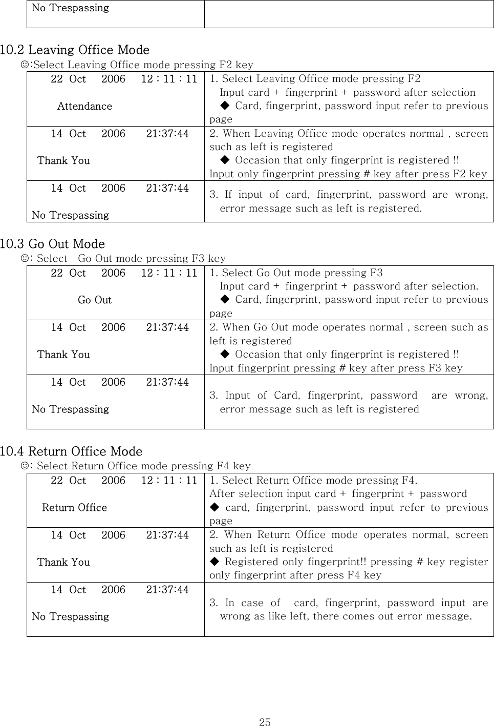
![24 9.6 In case of fingerprint + password use ☺ It is available to Finger + PIN article in exit and entrance method setting was selected !! 9.7 In case of card + password + fingerprint use ☺ It is available to Card + PIN + Finger article in exit and entrance method setting was selected !! RF CARD 1. if put close registered RF card on RF card contact part of device, card is realized. Please Touch Finger 2. When input right card, screen that can input fingerprint as like left is registered. When input correct fingerprint, password input screen is registered. Need Password check [ _ ] * Back # NEXT F1 Cancel F4 OK 3. if press # or F4 button after input exactly password, the door opens. If password does not conform, error message is registered and the door does not open. 10. Selection and Use of Entrance/Exit Control Mode 10.1 Attendance Mode ☺: select Attendance mode pressing F1 key 22 Oct 2006 12 : 11 : 11 Attendance 1. Select Attendance Mode pressing F1 key. After selection input card + fingerprint + password. ◆ card, fingerprint, password input refer to previous page 14 Oct 2006 21:37:44 Thank You 2. When Attendance mode operates normal, screen such as left is registered. ◆ When registered only fingerprint !! Input fingerprint pressing # key after press F1 key 14 Oct 2006 21:37:44 3. Card, fingerprint, password input were wrong, error message such as left is registered. Please Touch Finger 1. Can input fingerprint if press # button. Input fingerprint registered in fingerprint reader. Need Password check [ _ ] * Back # NEXT F1 Cancel F4 OK 2. Can input password as like left when input correct fingerprint. If press # or F4 button after input password, the door opens 14 Oct 2006 21:37:44 No Trespassing 3. When input wrong fingerprint or password or do not input password more than 3 seconds, error message is registered as like left.](https://usermanual.wiki/BRAINTECH/FM1000MF/User-Guide-964844-Page-24.png)