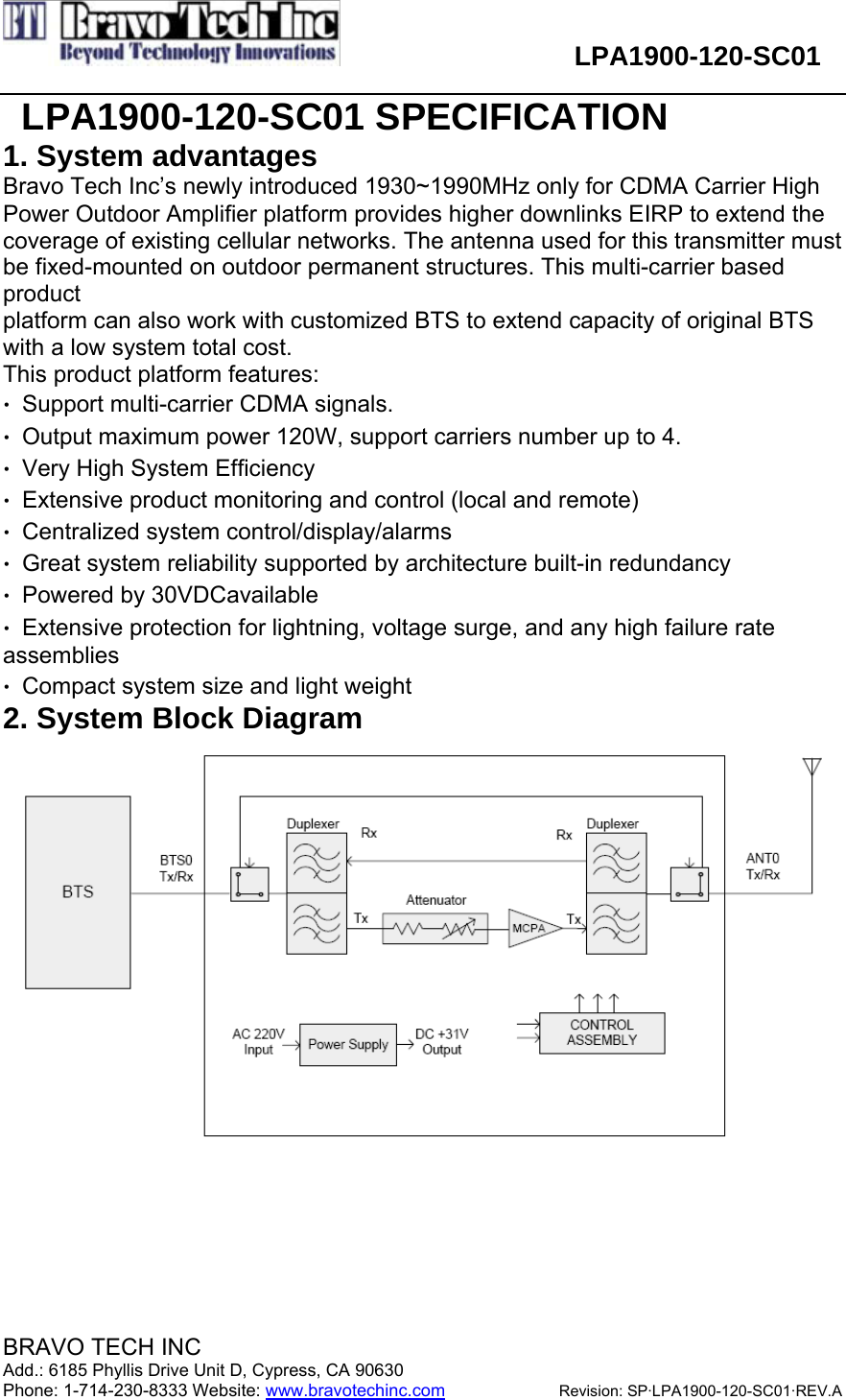
BTI Wireless LPA1900 Power Amplifier User Manual

Bravo Tech (Shenzhen) Co. Ltd. Power Amplifier

User Manual

                       LPA1900-120-SC01  BRAVO TECH INC                                       Add.: 6185 Phyllis Drive Unit D, Cypress, CA 90630 Phone: 1-714-230-8333 Website: www.bravotechinc.com             Revision: SP·LPA1900-120-SC01·REV.A   LPA1900-120-SC01 SPECIFICATION 1. System advantages Bravo Tech Inc’s newly introduced 1930~1990MHz only for CDMA Carrier High Power Outdoor Amplifier platform provides higher downlinks EIRP to extend the coverage of existing cellular networks. The antenna used for this transmitter must be fixed-mounted on outdoor permanent structures. This multi-carrier based product platform can also work with customized BTS to extend capacity of original BTS with a low system total cost. This product platform features: •  Support multi-carrier CDMA signals. •  Output maximum power 120W, support carriers number up to 4. •  Very High System Efficiency •  Extensive product monitoring and control (local and remote) •  Centralized system control/display/alarms •  Great system reliability supported by architecture built-in redundancy •  Powered by 30VDCavailable •  Extensive protection for lightning, voltage surge, and any high failure rate assemblies •  Compact system size and light weight 2. System Block Diagram
                       LPA1900-120-SC01  BRAVO TECH INC                                       Add.: 6185 Phyllis Drive Unit D, Cypress, CA 90630 Phone: 1-714-230-8333 Website: www.bravotechinc.com             Revision: SP·LPA1900-120-SC01·REV.A     3. Electrical Specifications Parameter spectfication Frequency 1930 ~ 1990 MHz Output Power 120Watts max. ( CDMA2000) Spurious Emission -45dBc@Δf=885-1.25MHz, 30kHz RBW -55dBc@Δf=1.25-1.98MHz, 30kHz RBW -55dBc@Δf=1.25-2.25MHz, 30kHz RBW -13dBm@Δf=2.25-4MHz, 30kHz RBW RF Gain 57.0 ± 1.0dB @ frequency range, +30Vdc, room temp. Normal Operating Voltage +30Vdc±1.0Vdc Operating Voltage +29Vdc ~ +31Vdc RF Gain Variation over Voltage & Temperature ±1.0dB @ +29≤Vsup≤+31V, -30℃ to +55℃ Gain Flatness Peak to Peak 0.2dB over any 5MHz Input/Output Return Loss -18dB min. Output Protection Mismatch protected with isolator Efficiency ≥15%@+30Volts, Po=+50.8dBm Operating Temperature -30℃ to +55℃  (Air Temperature inside System), Operating point Output power:52.0dBm ± 0.5dB Operating range 6dB Input Power ALC B min Over Pwr Output Pwr:52dBm ± 0.5dB 4. Alarm and Functions Specifications TTL output for the alarm pins. Normal is High, Alarm is Low. 4.1 Over temperature alarm Alarm and shutdown at 95℃  base temperature, auto-recover at 90℃ base temperature. 4.2 Over power alarm Alarm and shutdown when output power is over 52.3dBm, no auto-recover. 4.3 ALC 4.3.1 ALC level: 52.0±0.5dBm 4.3.2 ALC range: ≥6dB 4.4 VSWR alarm Alarm and shutdown when reject is over 5, auto-recover at 3.
 LPA1900-120-SC01  BRAVO TECH INC     Add.: 6185 Phyllis Drive Unit D, Cypress, CA 90630     Phone: 1-714-230-8333  Website: www.bravotechinc.com Revision: SP·LPA1900-120-SC01·REV.APage: 3    5. Description of the connectors 5.1 RF  Part  Port Name  Type  Warning Input SMA Female (50Ω) Normal :-6.2dBm maxium input power +1dBm. Output N Female (50Ω) Normal :50.8dBm maxium output power 52.0dBm. 5.2 DC power            Port Name  Type  NO  Warning A1、A2  VDC    type +30V, range 24~32V DC IN D-Sub  type DSCD175PS1M (Male)  A3、A4  GND to VDC  5.3 Communication  Connector type:  USB Note:  Manufacturer  use  to  debug.  5.4 LED  Indication   Figure 1 Power Amplifier Indicators Table 1 Specification of Power Amplifier Indicator Light Item  Label  Color  State  Specification MAJOR ALM  Red  On MINOR ALM  Yellow  Off 1 RF ON  Green  Off Power amplifier alarms and    shuts down MAJOR ALM  Red  Off MINOR ALM  Yellow  On 2 RF ON  Green  Off Power amplifier alarms but still works MAJOR ALM  Red  Off 3 MINOR ALM  Yellow  Off Power amplifier works normally
 LPA1900-120-SC01  BRAVO TECH INC     Add.: 6185 Phyllis Drive Unit D, Cypress, CA 90630     Phone: 1-714-230-8333  Website: www.bravotechinc.com Revision: SP·LPA1900-120-SC01·REV.APage: 4   RF ON  Green  On 5.5 Warning 1. Check the power supply voltage is between 24V and 32V or not before electrify, better   to setup in 30V. Power of power supply shall bigger than 1400W. 2. Ensure the power supply polarity is right, port A1、A2 are anode, and port A3、A4 are  cathode. 3. Ensure the output line is connected and input power is not over load before connect   the RF input line. 4. Use the type N connector as output connector, for the high output power, suggest to  using the φ3 upwards RF cable to connect. At the same time, output matching demand all right, SWR more than 1.5 is better, but less than 3.0. 5. Product operating should be cooled by air flow, air flow more than 150cfm. 6. Product operating room temperature can’t above 50o  ,also can’t below -20o。
 LPA1900-120-SC01  BRAVO TECH INC     Add.: 6185 Phyllis Drive Unit D, Cypress, CA 90630     Phone: 1-714-230-8333  Website: www.bravotechinc.com Revision: SP·LPA1900-120-SC01·REV.APage: 5    6. Dimension   Figure 2 Dimension                399 486 Left  Right FrontRear Unit: mm
 LPA1900-120-SC01  BRAVO TECH INC     Add.: 6185 Phyllis Drive Unit D, Cypress, CA 90630     Phone: 1-714-230-8333  Website: www.bravotechinc.com Revision: SP·LPA1900-120-SC01·REV.APage: 6        Figure 3 Mechanical drawing
 LPA1900-120-SC01  BRAVO TECH INC     Add.: 6185 Phyllis Drive Unit D, Cypress, CA 90630     Phone: 1-714-230-8333  Website: www.bravotechinc.com Revision: SP·LPA1900-120-SC01·REV.APage: 7   7 Assembly  The LPA1900 is assembled to an outdoor Booster. It can be push into the Booster along the guide rail.    Figure 4 the guide rail for LPA1900 assembly
 LPA1900-120-SC01  BRAVO TECH INC     Add.: 6185 Phyllis Drive Unit D, Cypress, CA 90630     Phone: 1-714-230-8333  Website: www.bravotechinc.com Revision: SP·LPA1900-120-SC01·REV.APage: 8    Below pictures show the location of an assembled LPA1900.     Figure 5 the front side of an assembled LPA1900
 LPA1900-120-SC01  BRAVO TECH INC     Add.: 6185 Phyllis Drive Unit D, Cypress, CA 90630     Phone: 1-714-230-8333  Website: www.bravotechinc.com Revision: SP·LPA1900-120-SC01·REV.APage: 9        Figure 6 the rear side of an assembled LPA1900
 LPA1900-120-SC01  BRAVO TECH INC     Add.: 6185 Phyllis Drive Unit D, Cypress, CA 90630     Phone: 1-714-230-8333  Website: www.bravotechinc.com Revision: SP·LPA1900-120-SC01·REV.APage: 10    There are three ports on the back of LPA1900. The SMA port is input signal port, the N-type port is output port and the D-Sub port is power supply.       Figure 7 the location of connectors
Information to the user This device complies with Part 15 of the FCC Rules. Operation is subject to the following two conditions: (1) this device may not cause harmful interference, and (2) this device must accept any interference received, including interference that may cause undesired operation.  Changes or modifications not expressly approved by the party responsible for compliance could void the user's authority to operate the equipment.  This equipment has been tested and found to comply with the limits for a Class A digital device, pursuant to Part 15 of the FCC Rules. These limits are designed to provide reasonable protection against harmful interference when the equipment is operated in a commercial environment. This equipment generates, uses, and can radiate radio frequency energy and, if not installed and used in accordance with the instruction manual, may cause harmful interference to radio communications. Operation of this equipment in a residential area is likely to cause harmful interference in which case the user will be required to correct the interference at his own expense.  This device must be installed by a professional installer. The antenna(s) used for this transmitter must be fixed-mounted on outdoor permanent structures. RF exposure compliance is addressed at the time of licensing, as required by the responsible FCC Bureau(s) including antenna co-location requirements acc to §1.1307(b)(3).

Navigation menu