BTI Wireless MBSC0700040RU The Remote Unit on BTI DAS system User Manual MBSC0700 040 RUx
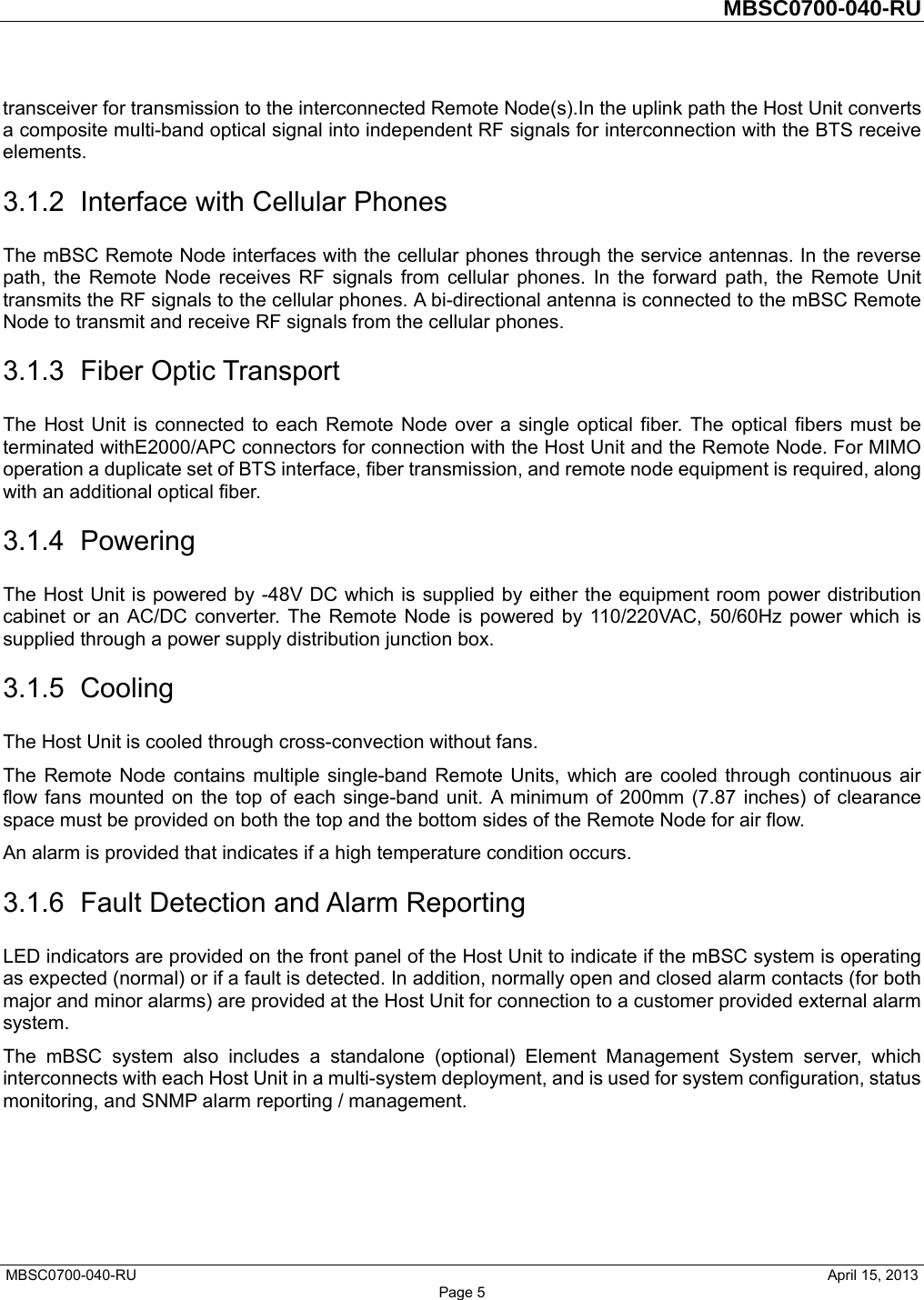
Bravo Tech (Shenzhen) Co. Ltd. The Remote Unit on BTI DAS system MBSC0700 040 RUx
Contents
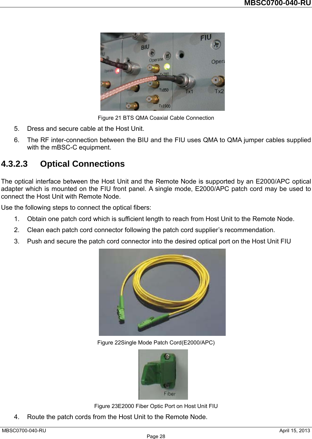
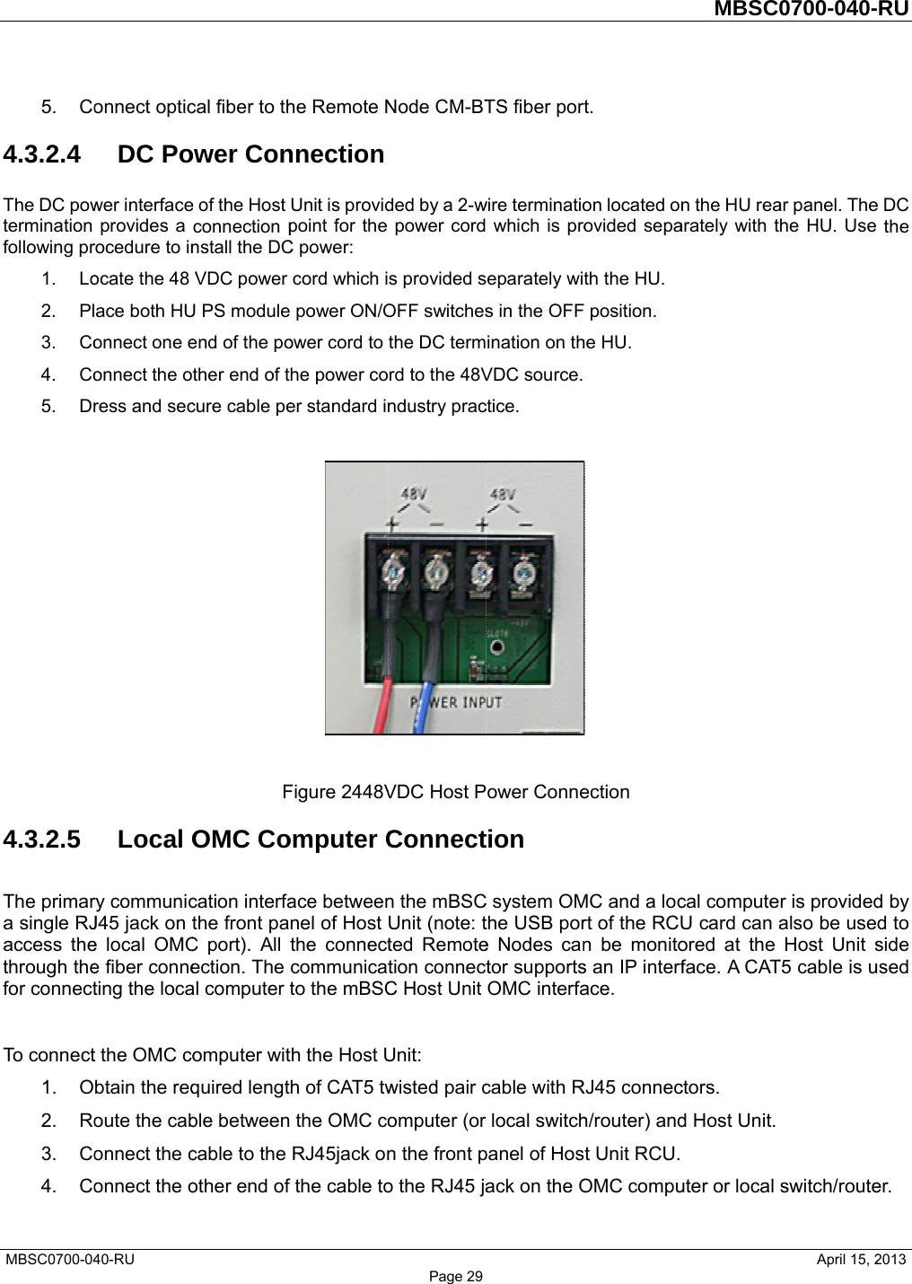
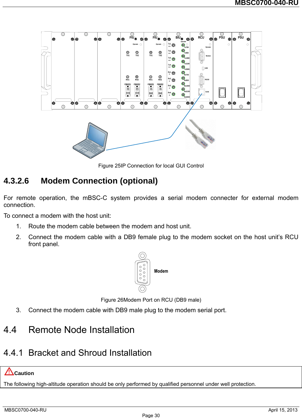
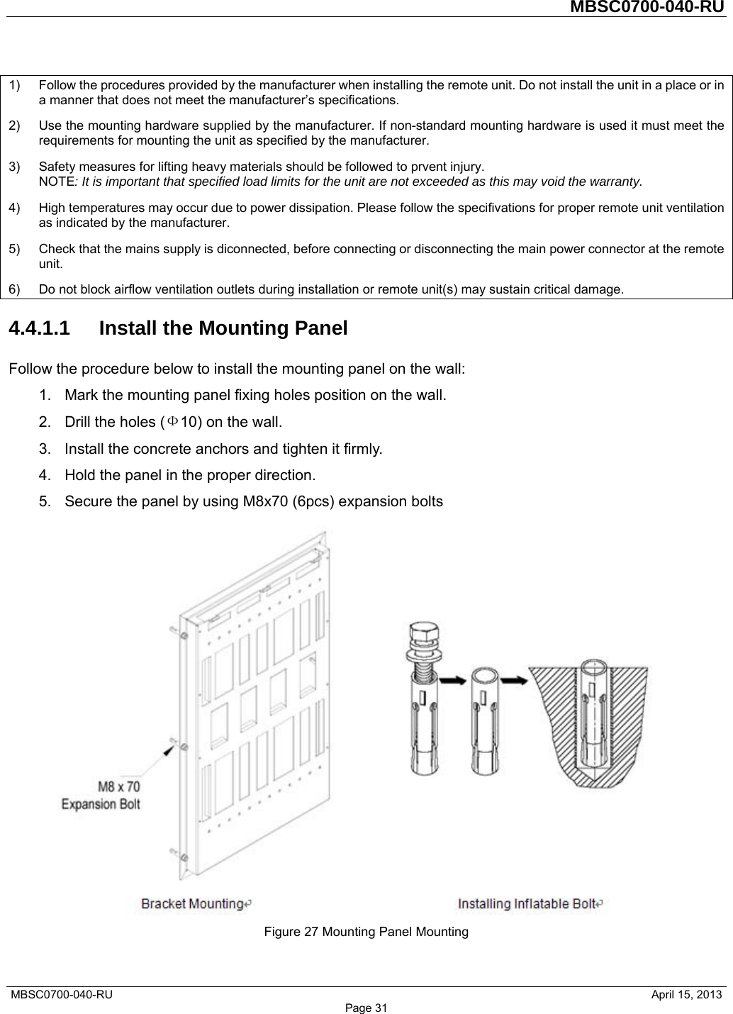
- 1. Users Manual
- 2. Users Manual V2
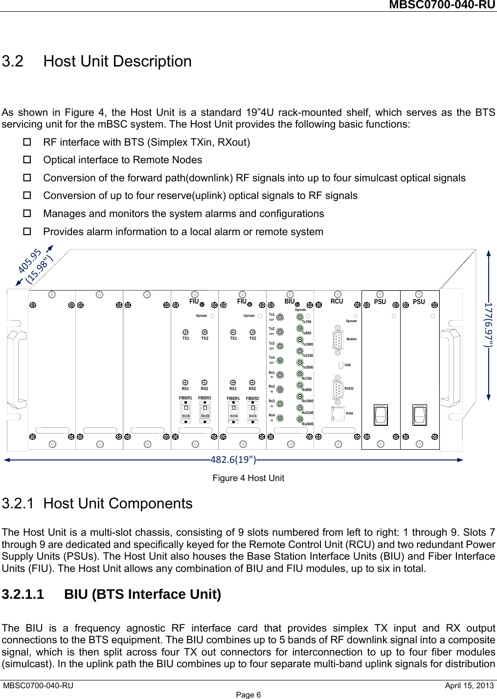
- 3. Revised users manual (same as 1/10/14)
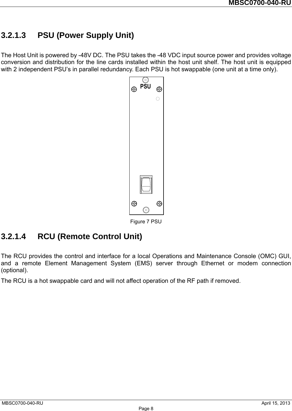
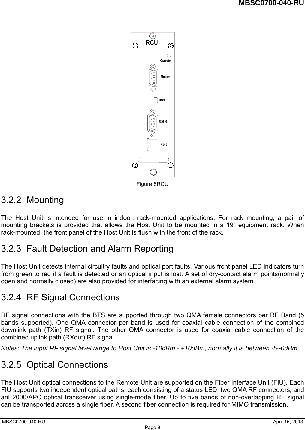
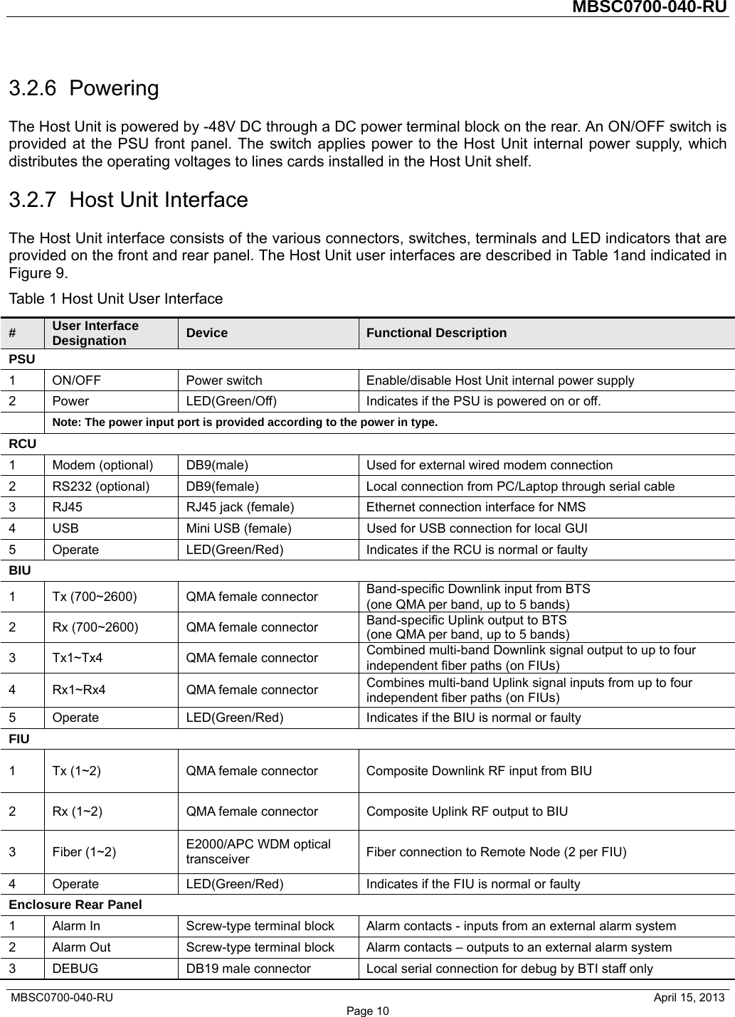
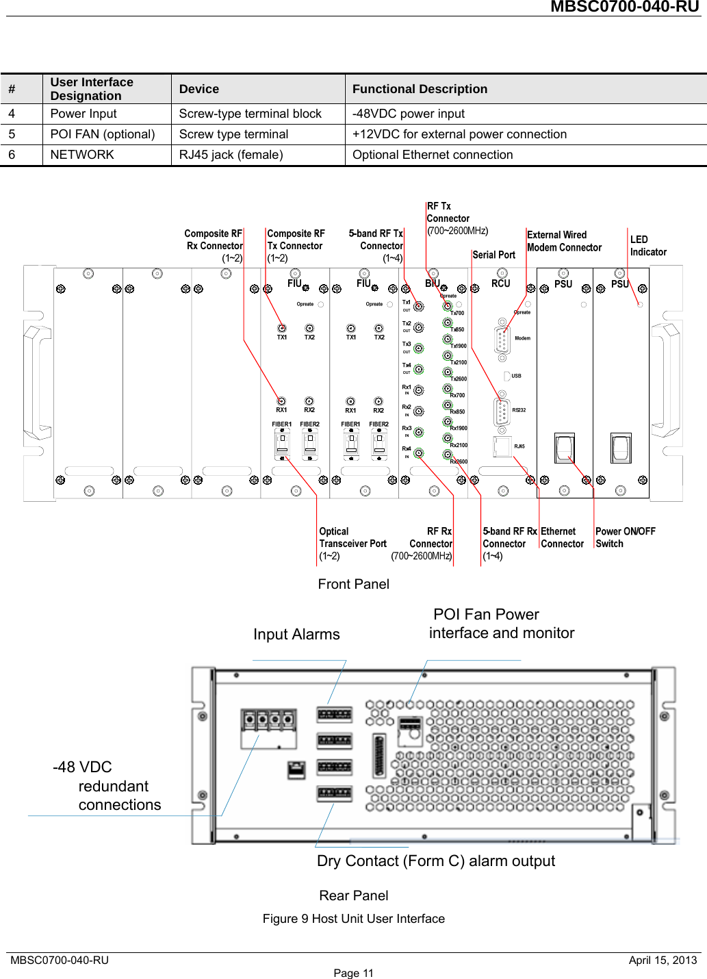
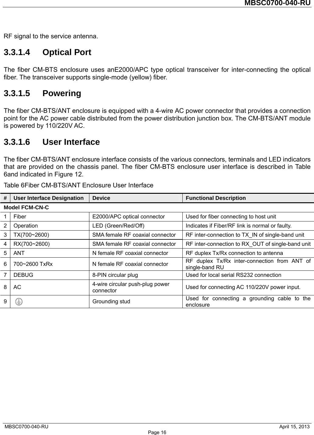
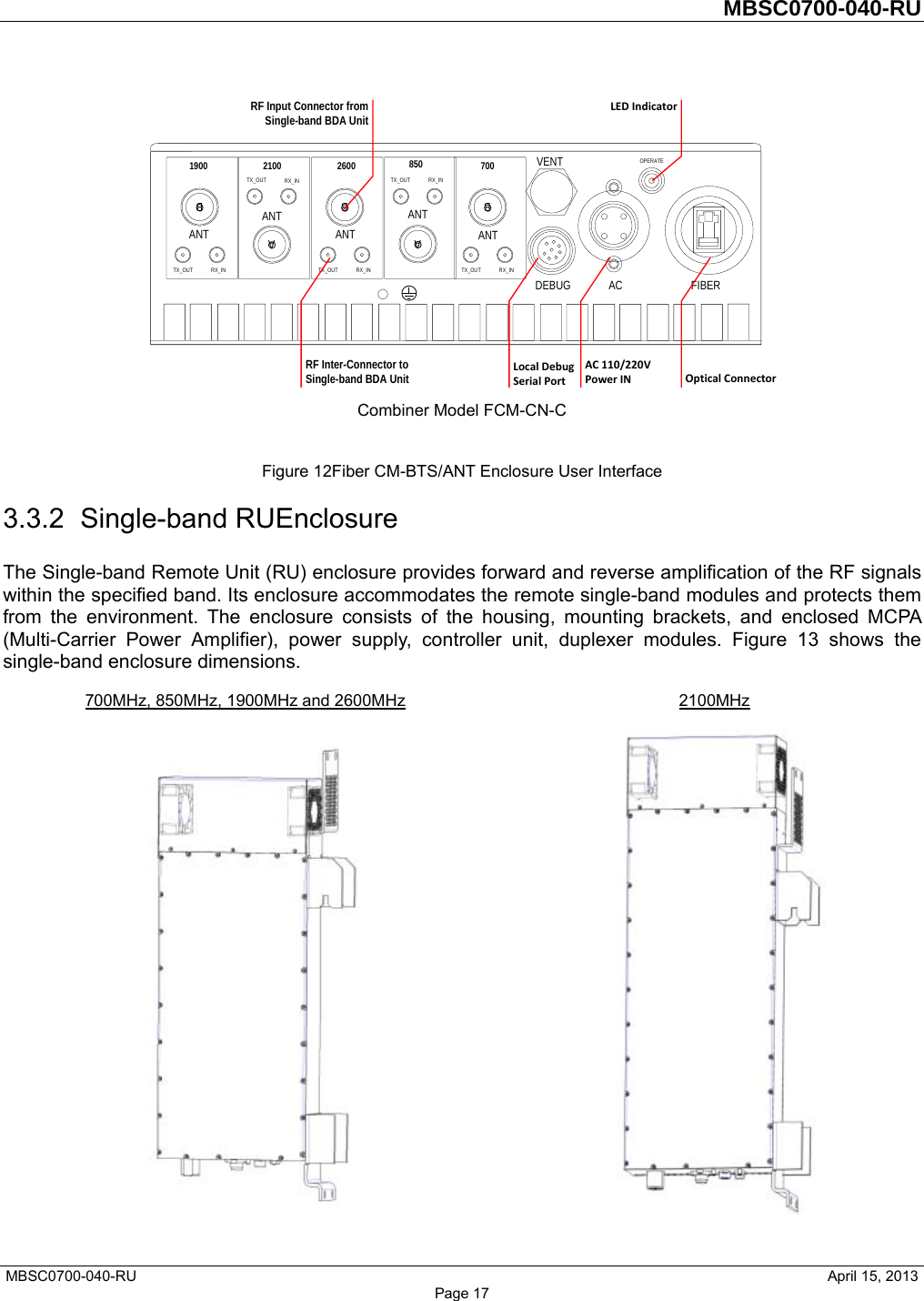
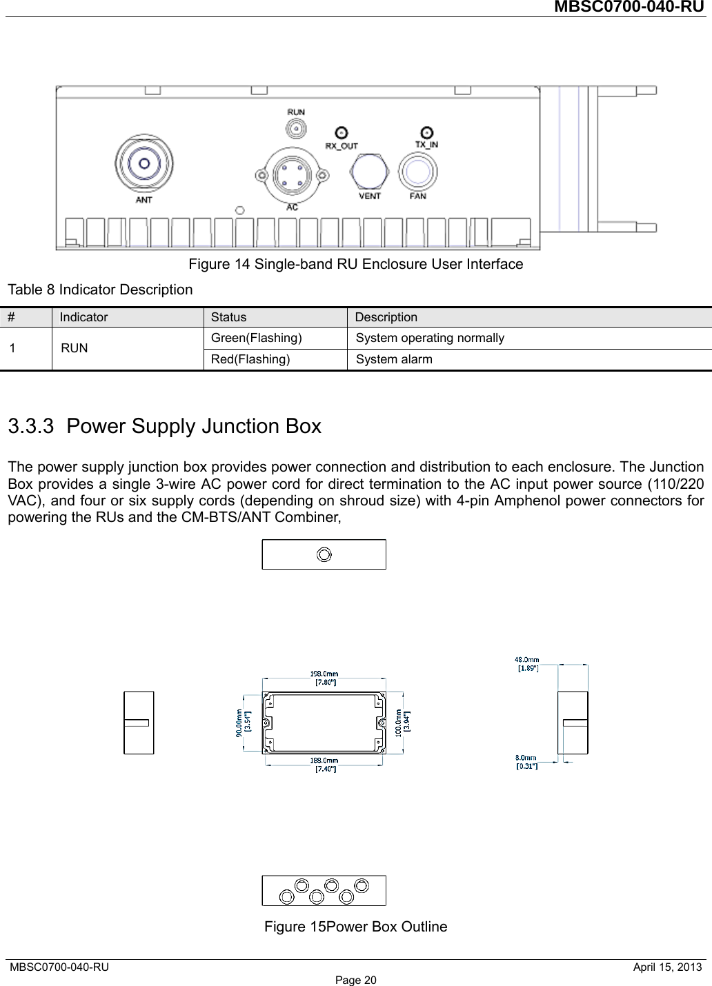
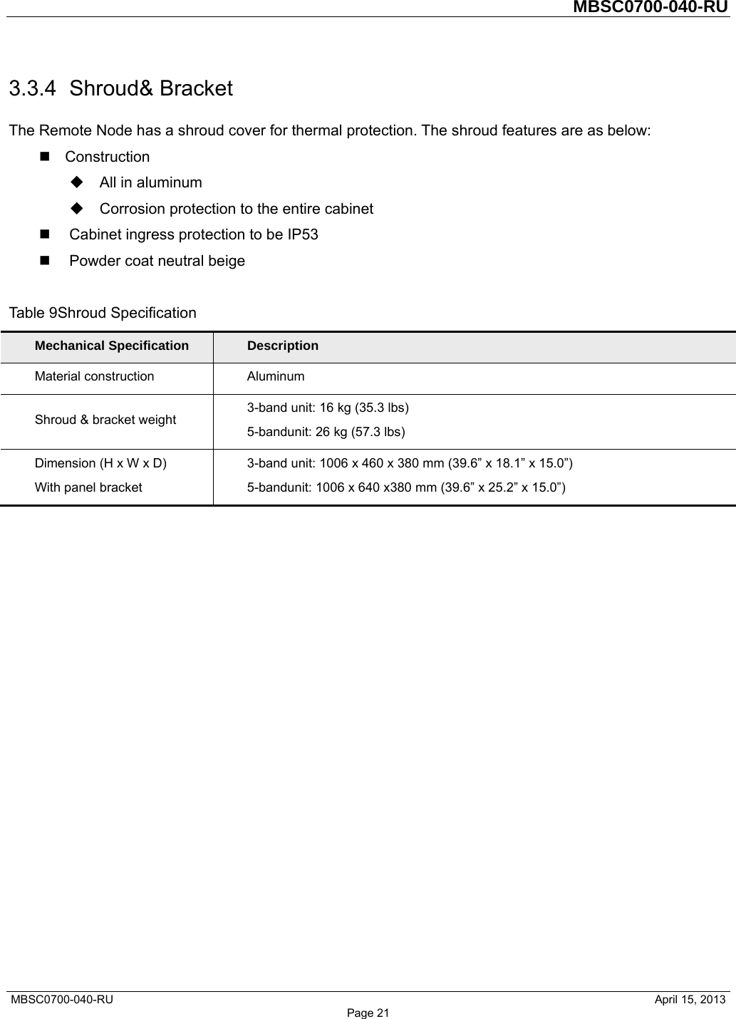
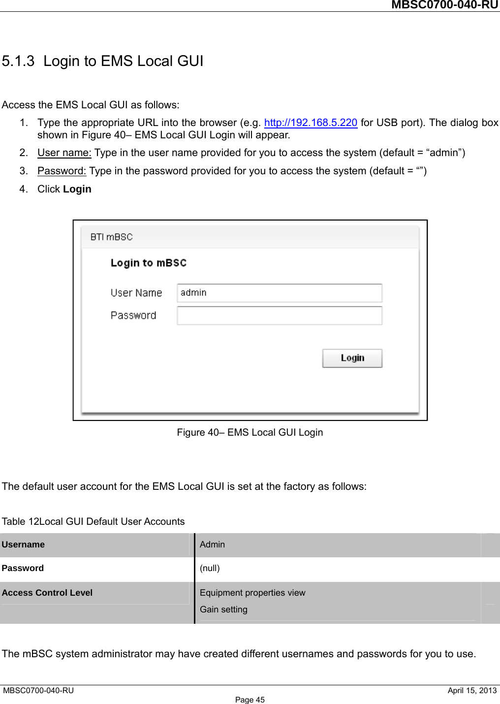
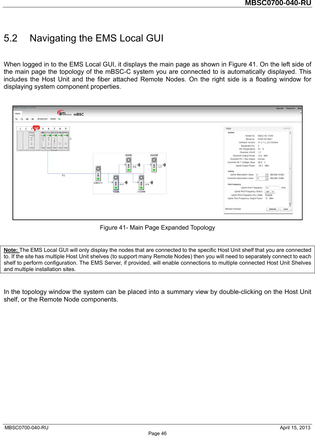
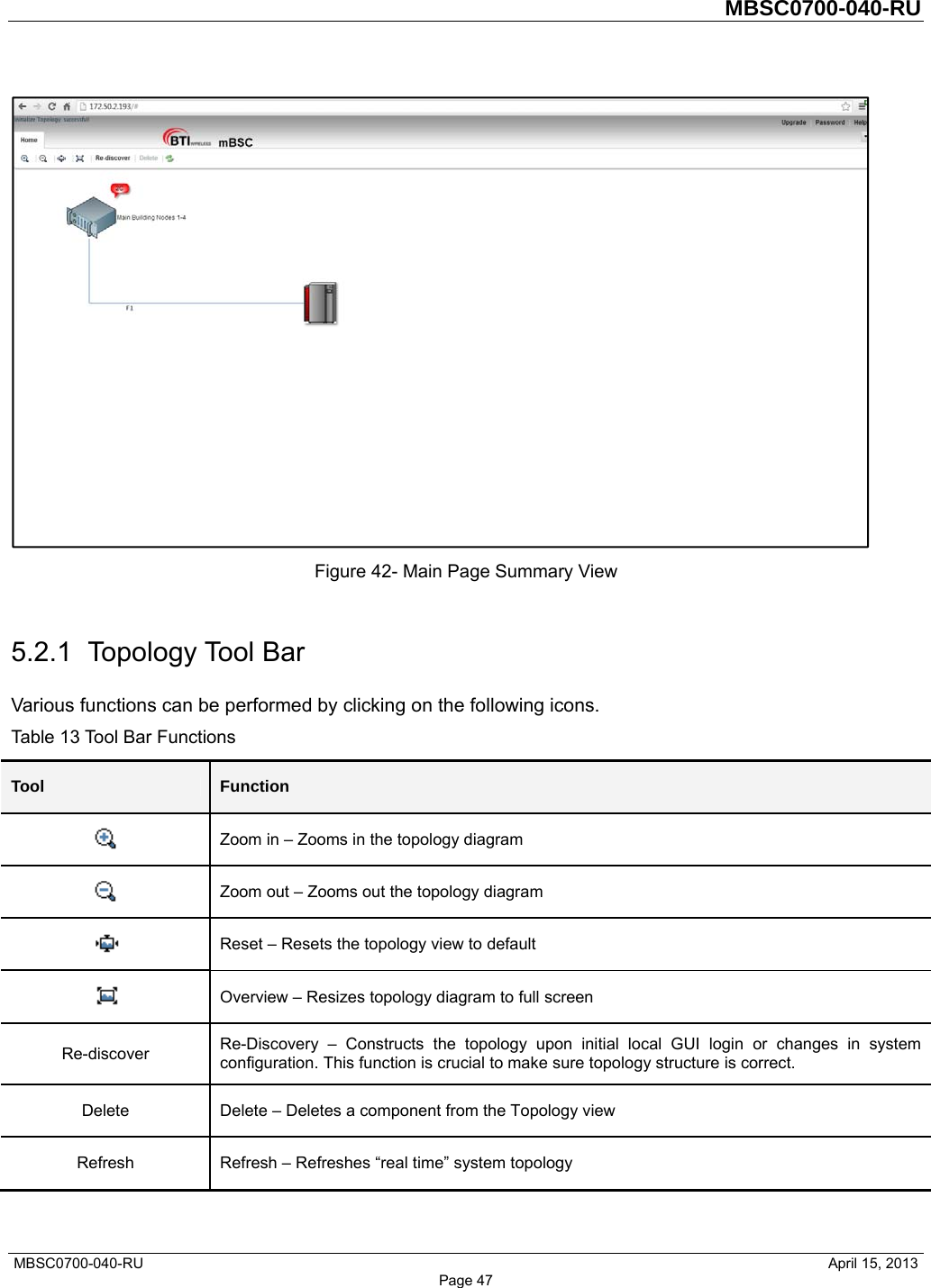
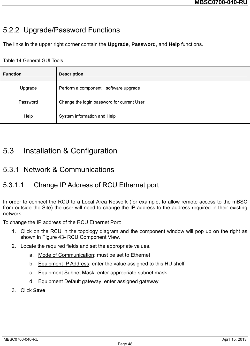
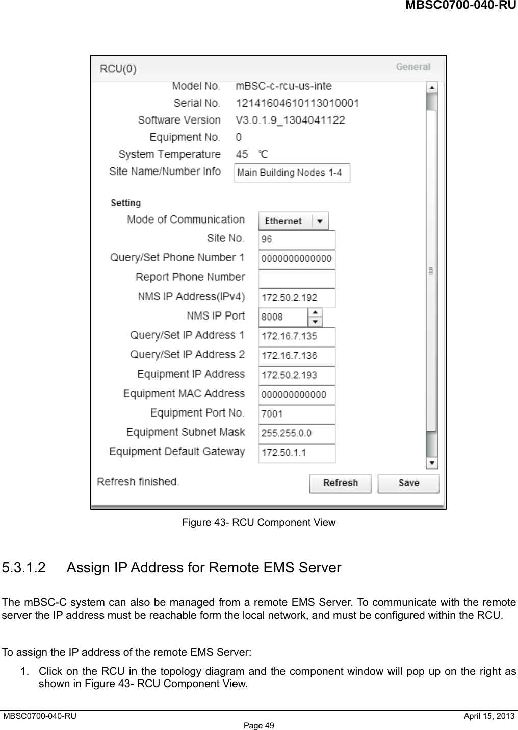
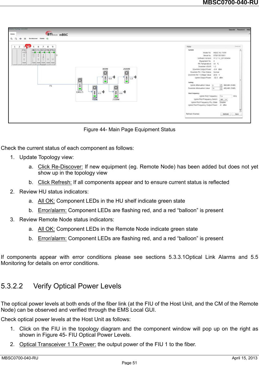
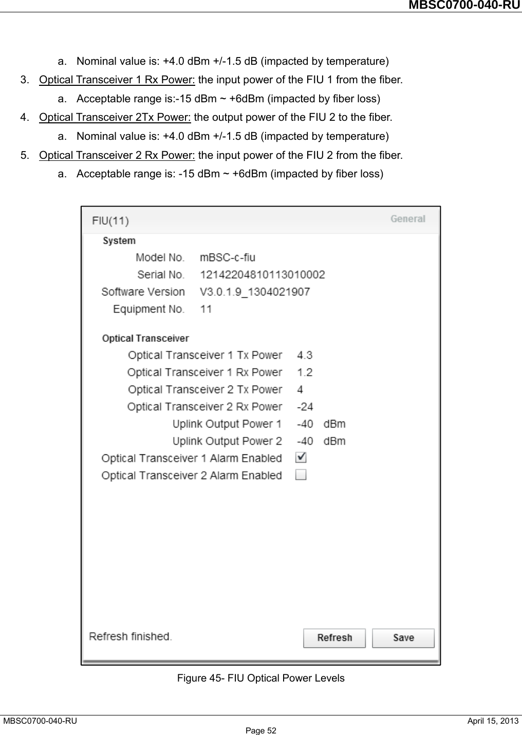
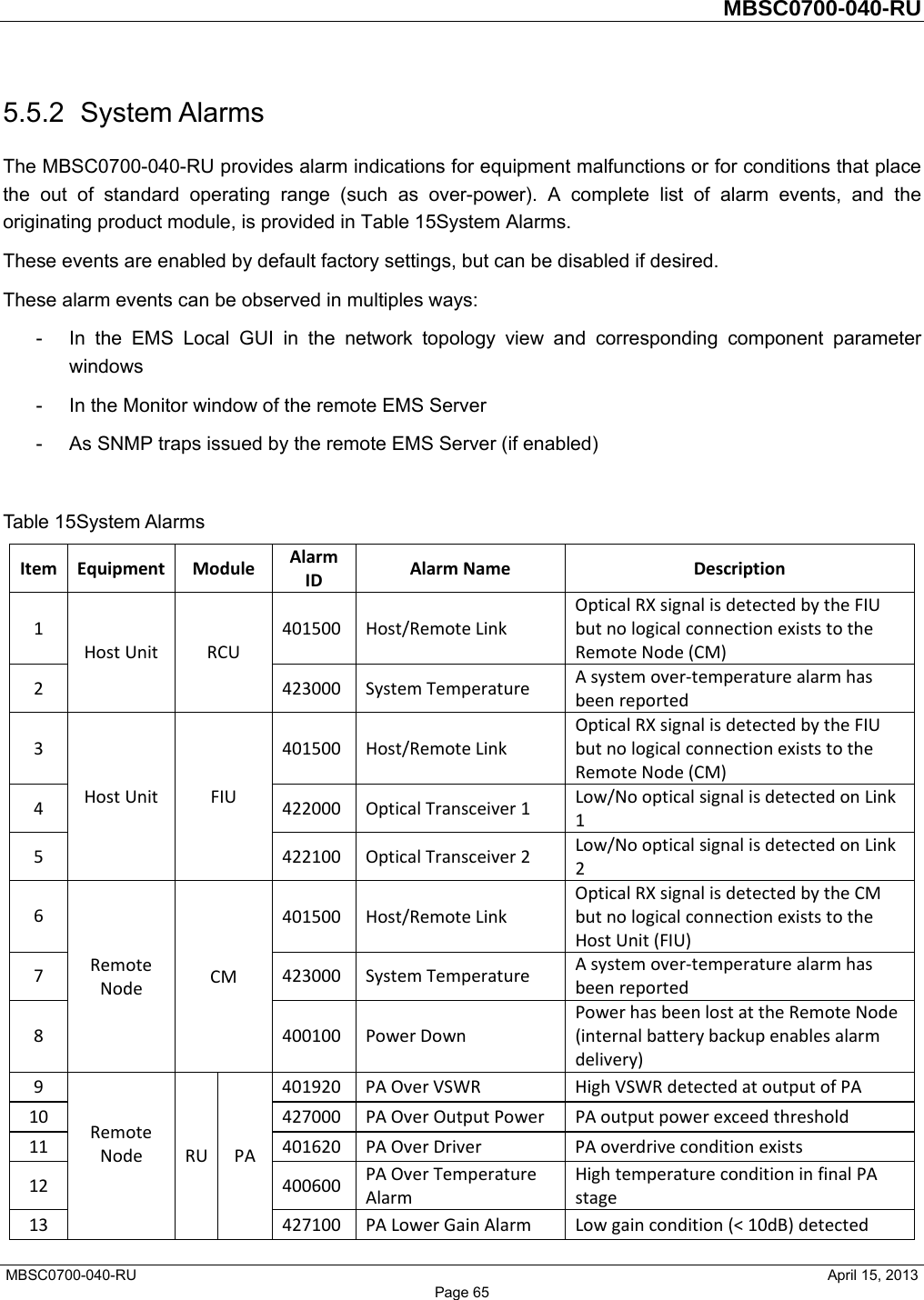
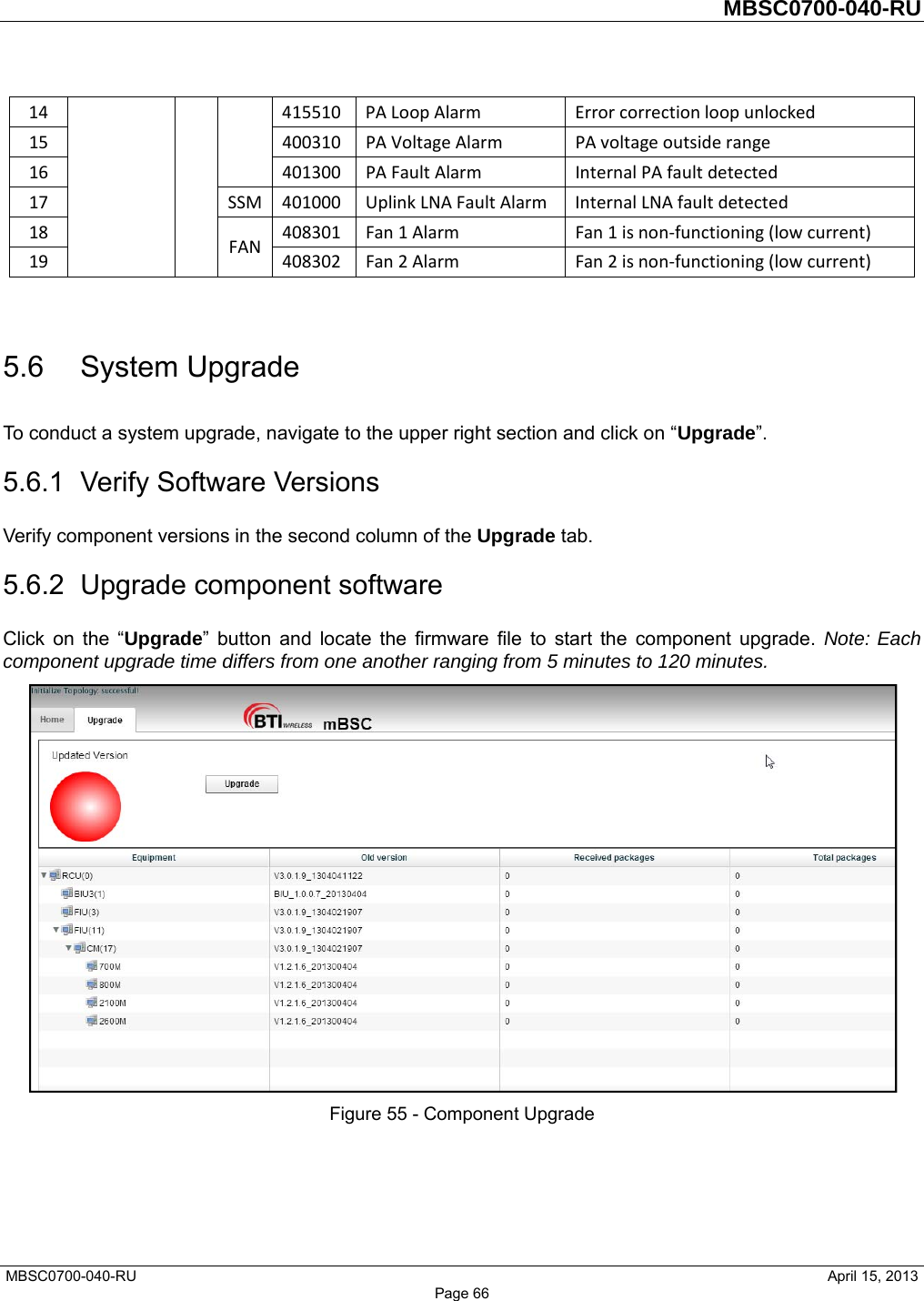
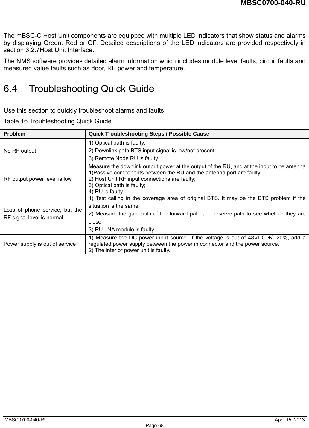
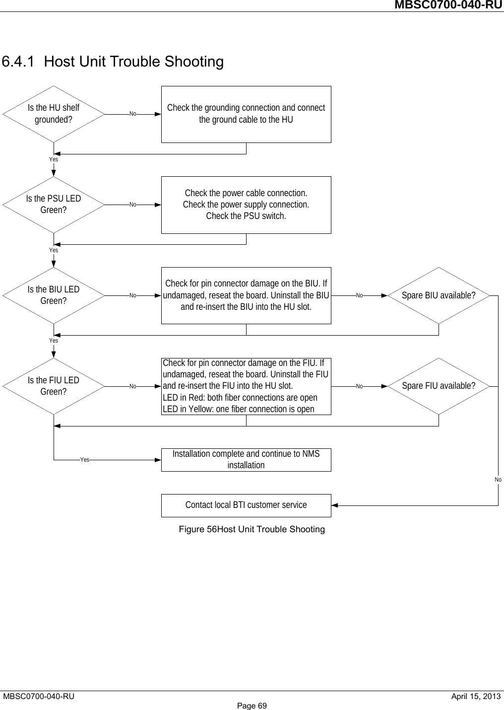
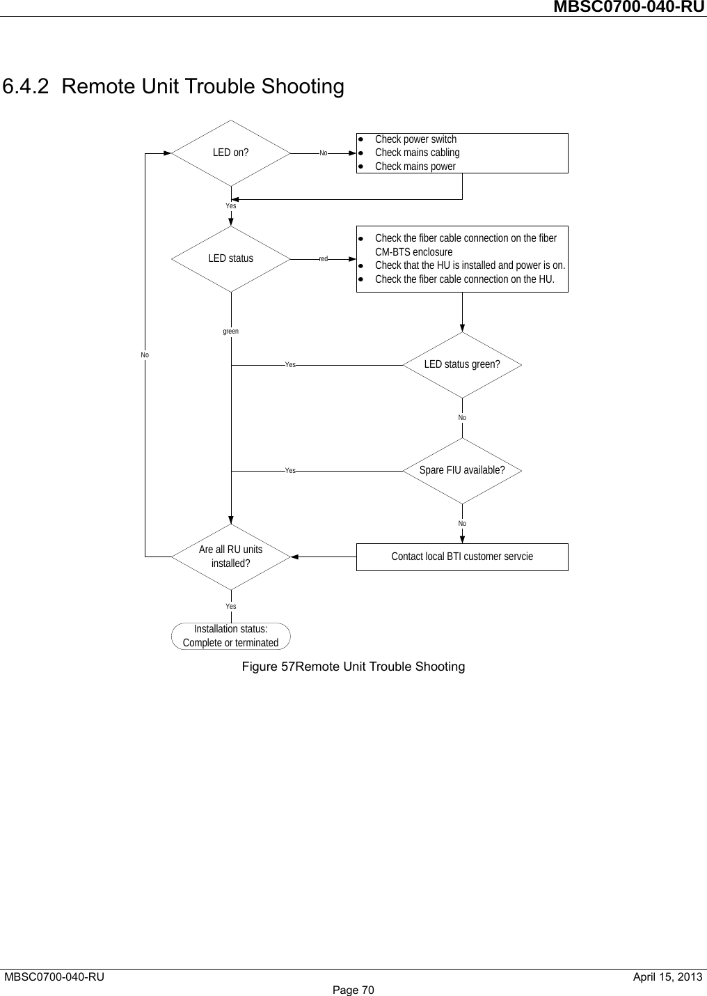
Users Manual