BTI Wireless MBSC0800040RU The Remote Unit on BTI DAS system User Manual MBSC0800 040 RUx
Bravo Tech (Shenzhen) Co. Ltd. The Remote Unit on BTI DAS system MBSC0800 040 RUx
UserManual.wiki
>
BTI Wireless
>
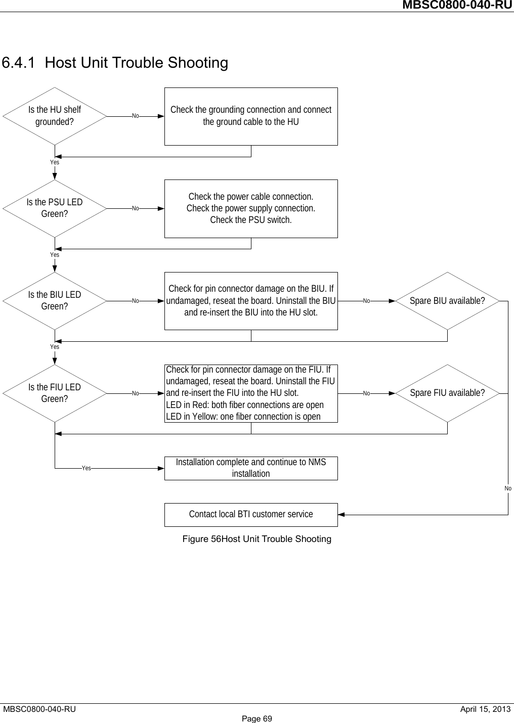
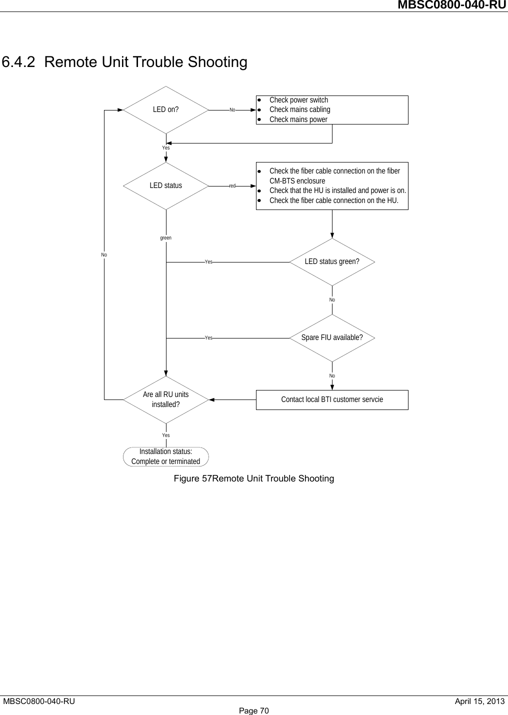
MBSC0800040RU User Manual
Users Manual
Navigation menu
Upload a User Manual
Namespaces
Wiki Guide
HTML
PDF
Info
Views
User Manual
Discussion / Help
Navigation