BTI Wireless MBSC2100-040 mBSC-040 DAS System User Manual
Bravo Tech (Shenzhen) Co. Ltd. mBSC-040 DAS System
UserManual.wiki
>
BTI Wireless
>
MBSC2100 040 User Manual
user manual
Navigation menu
Upload a User Manual
Namespaces
Wiki Guide
HTML
PDF
Info
Views
User Manual
Discussion / Help
Navigation
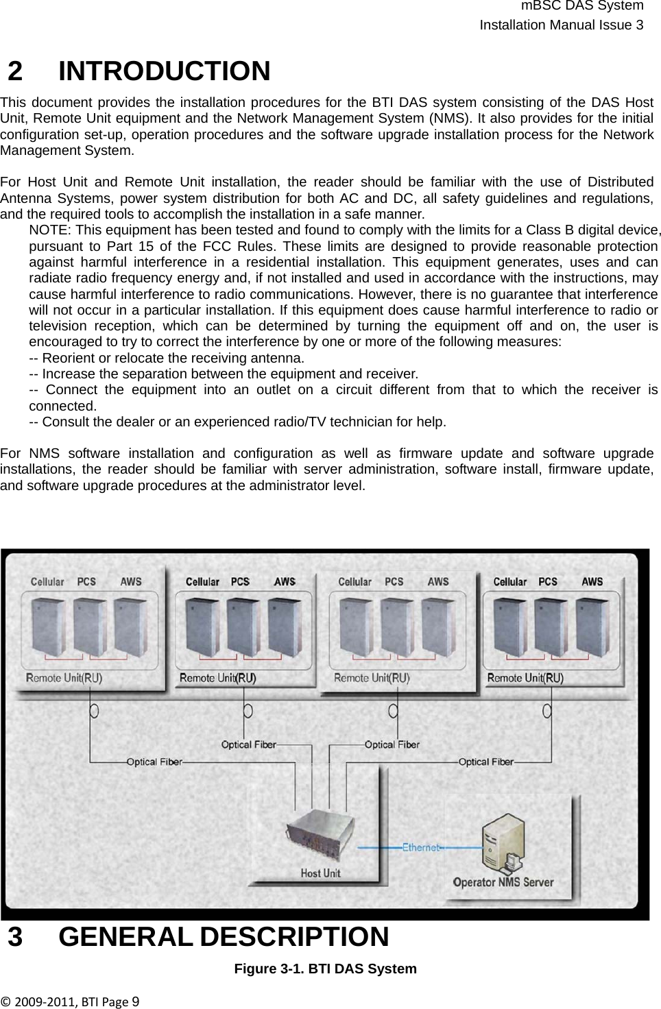
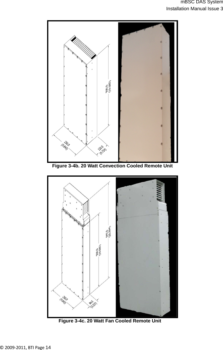
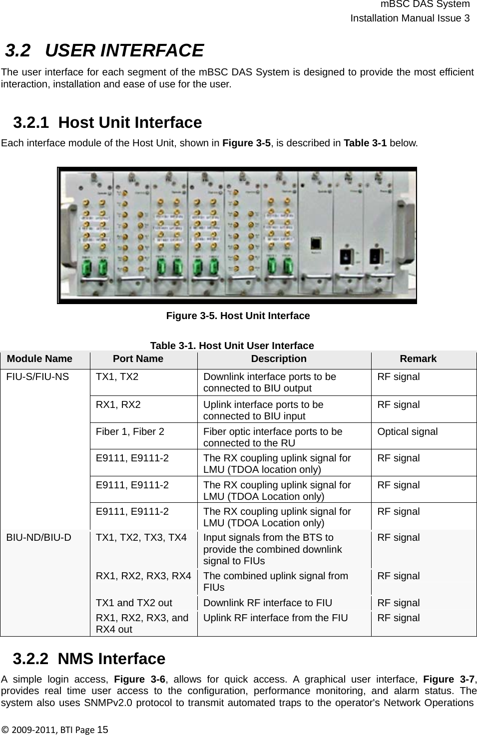
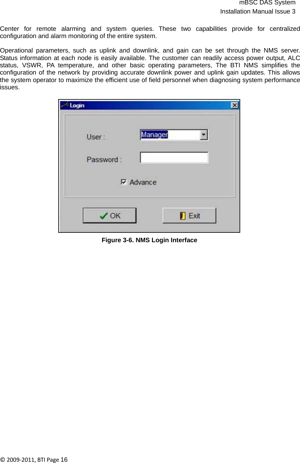
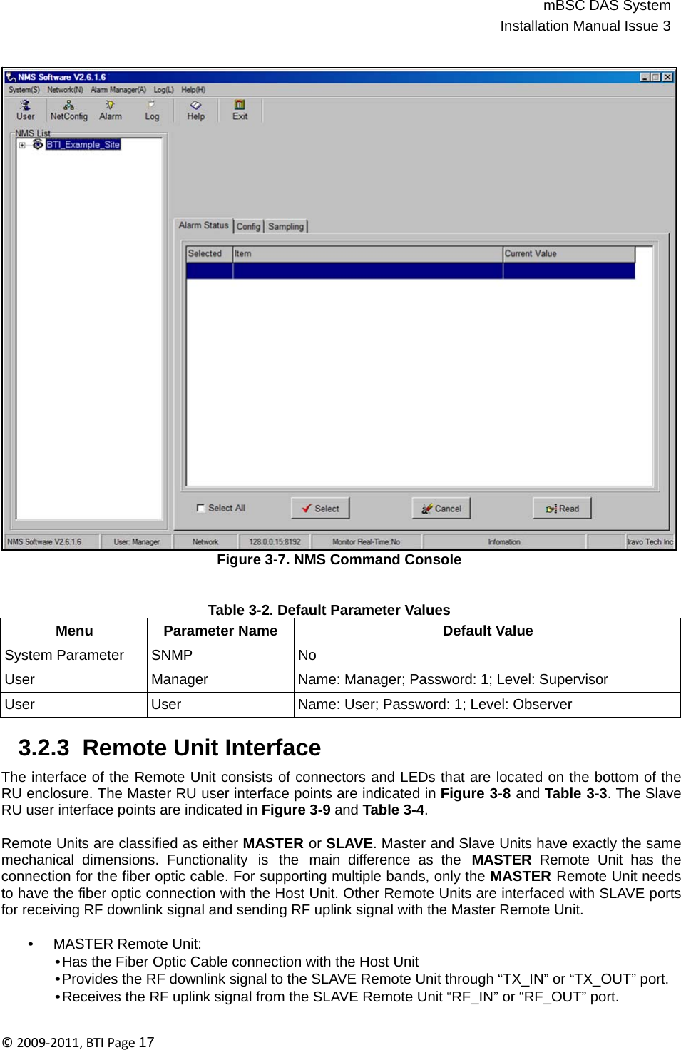
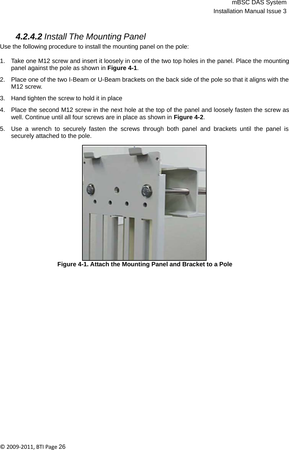
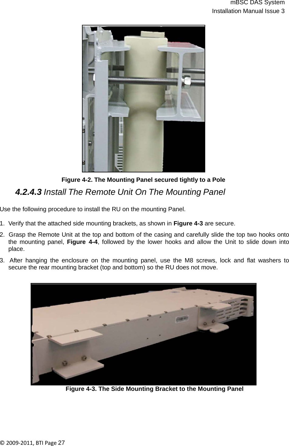
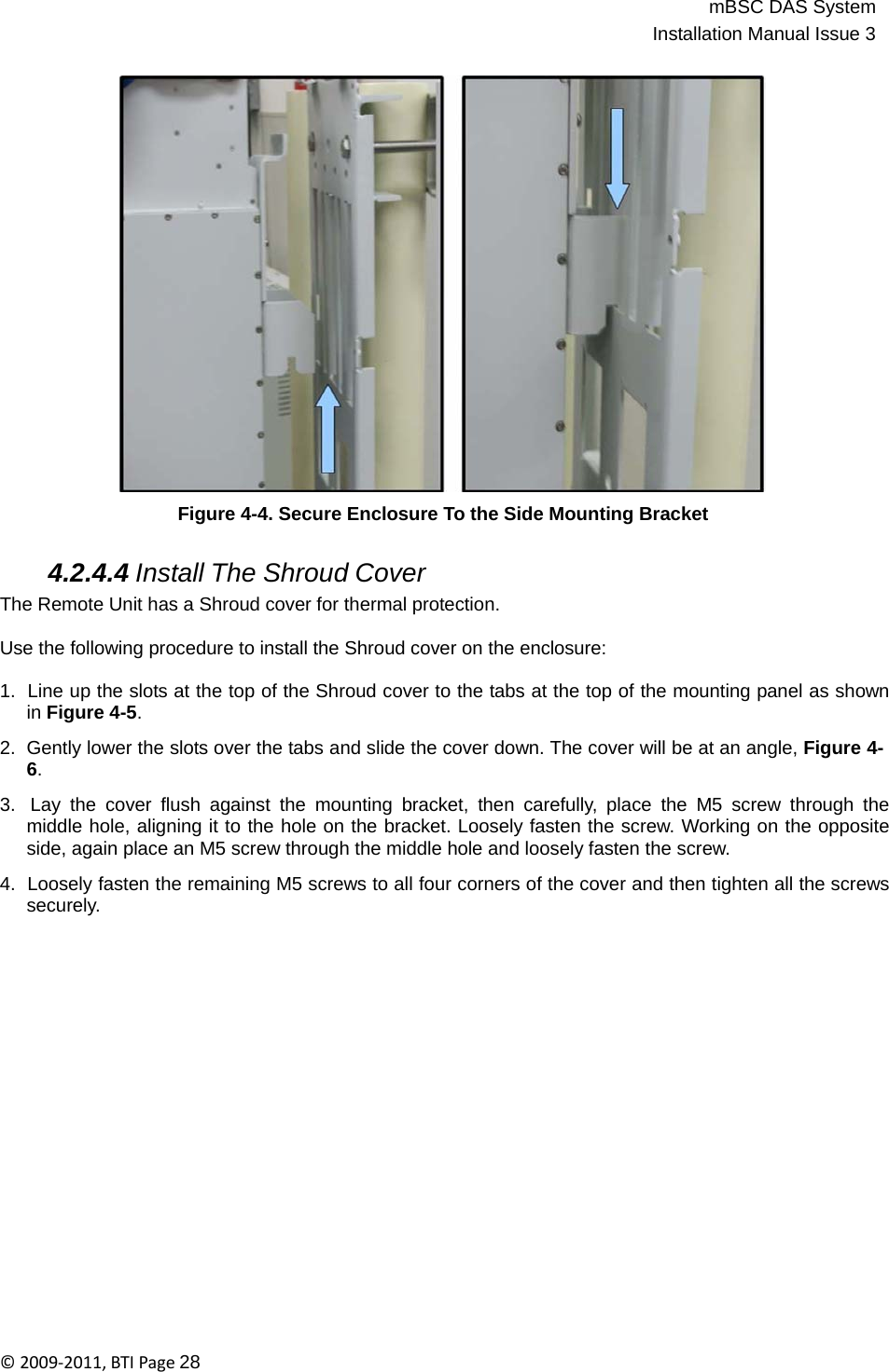
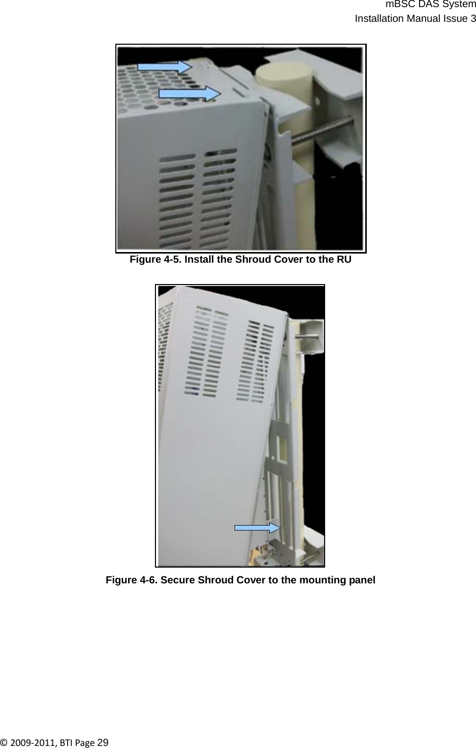
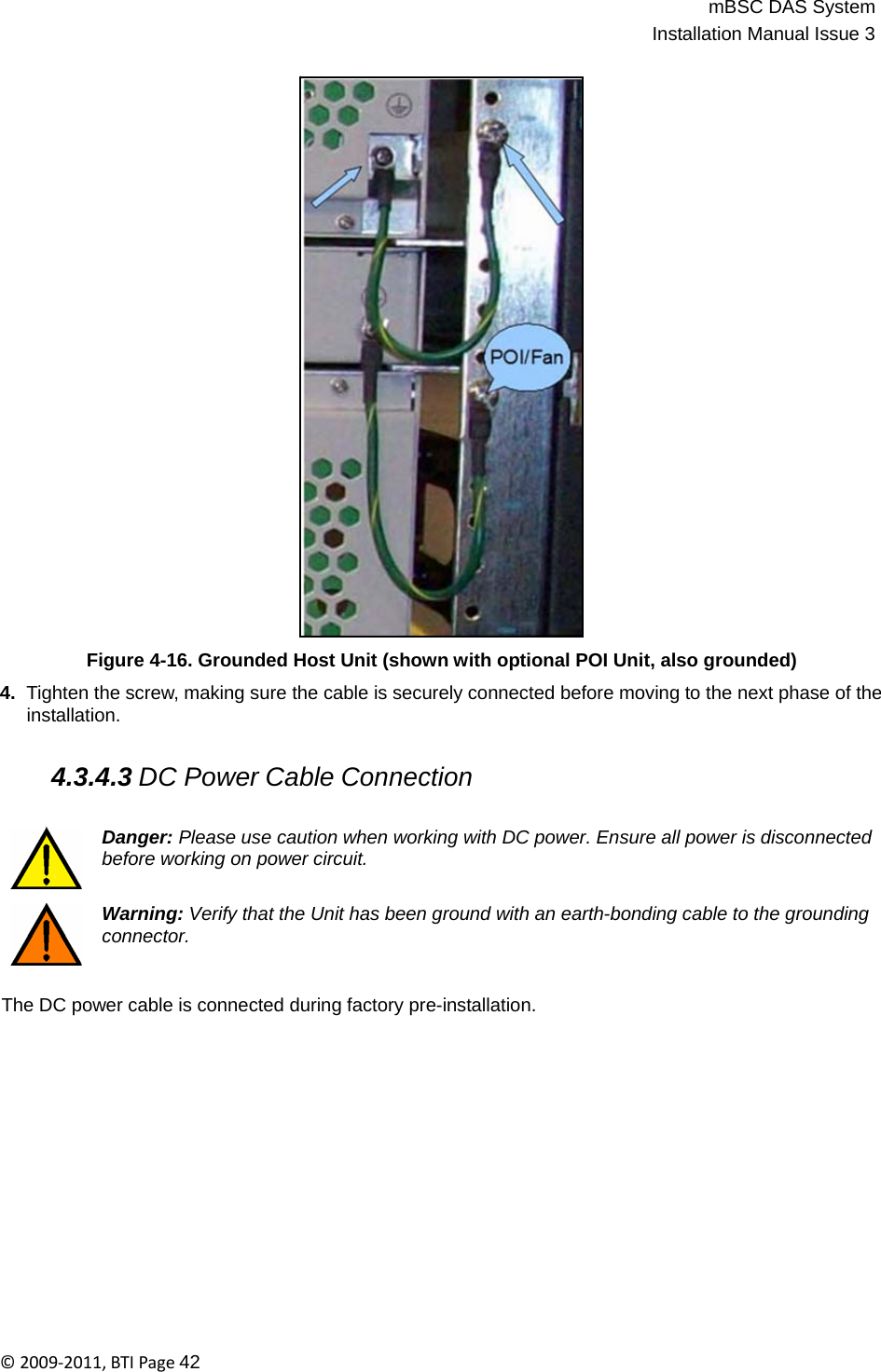
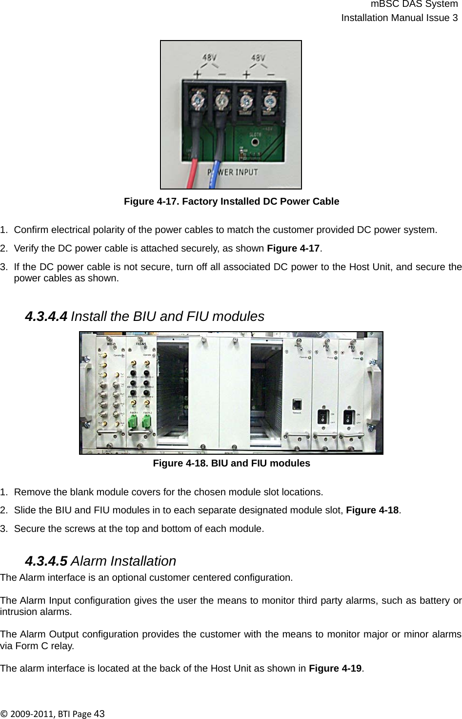
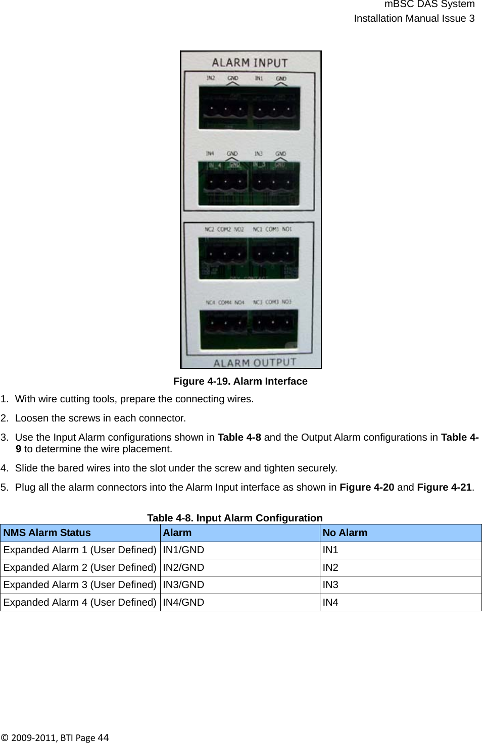
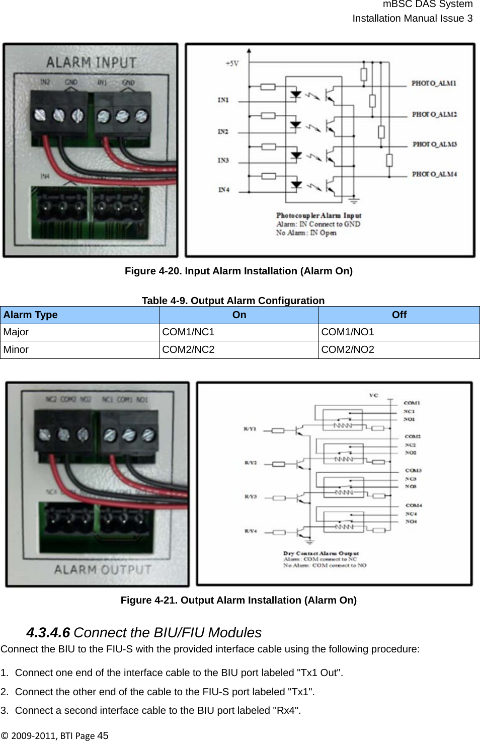
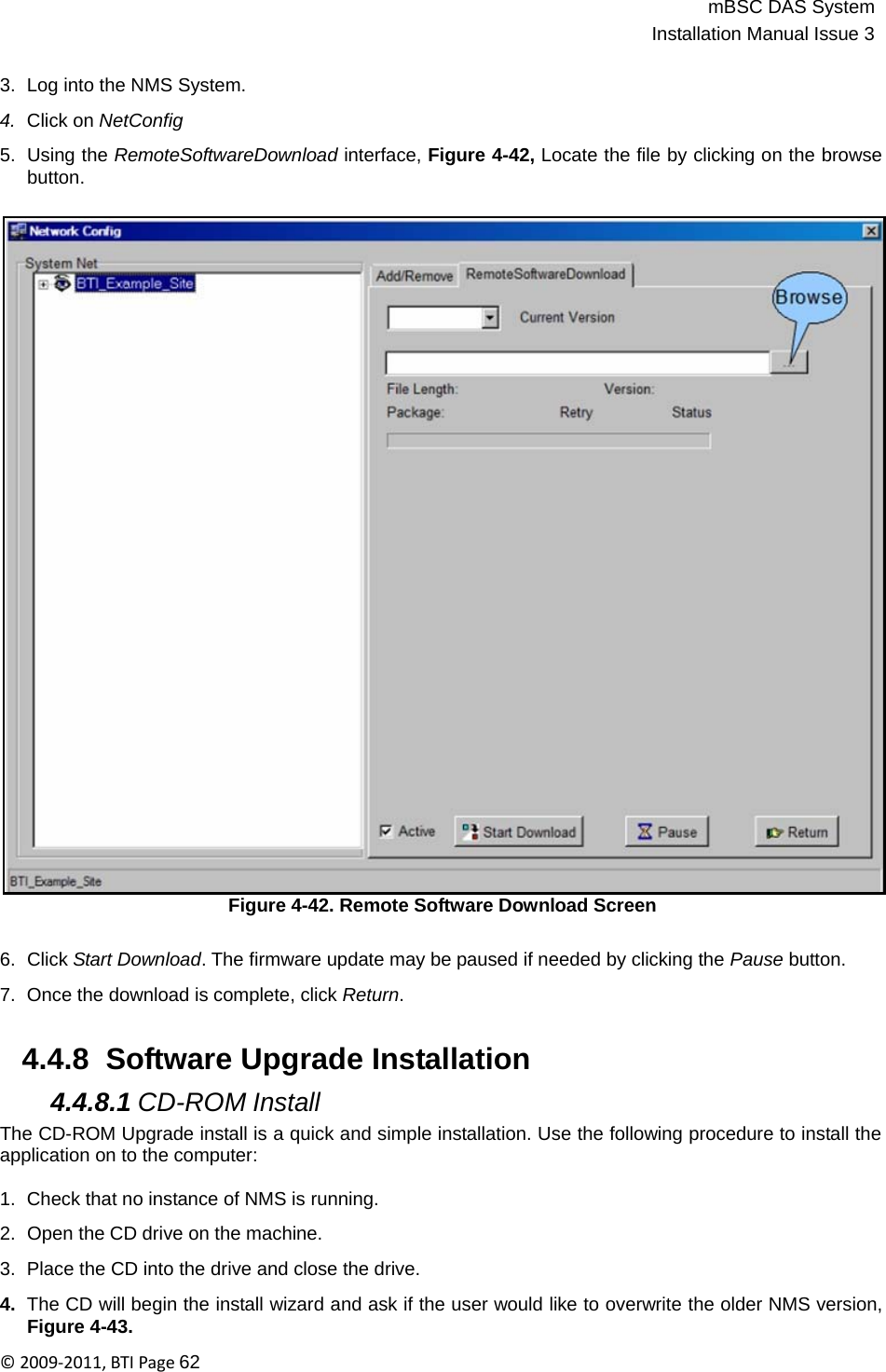
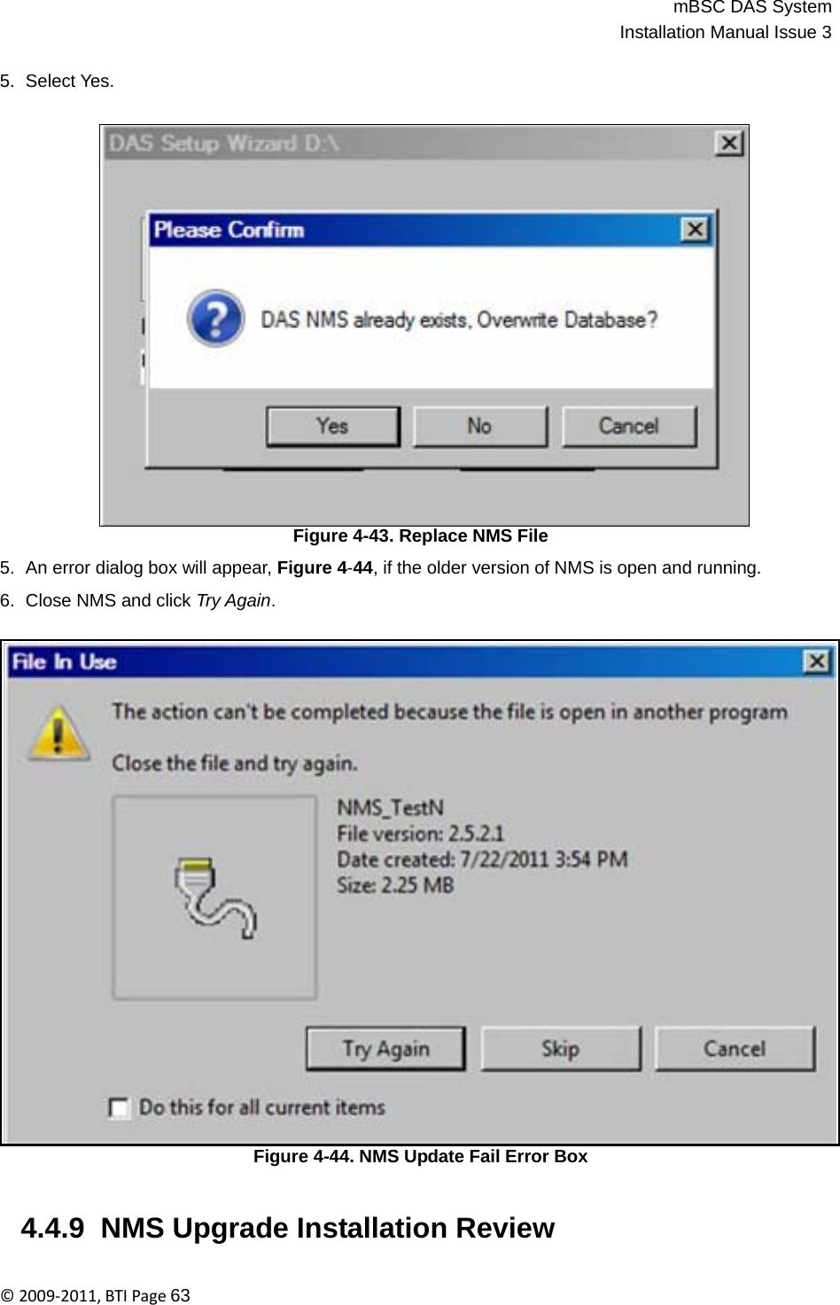
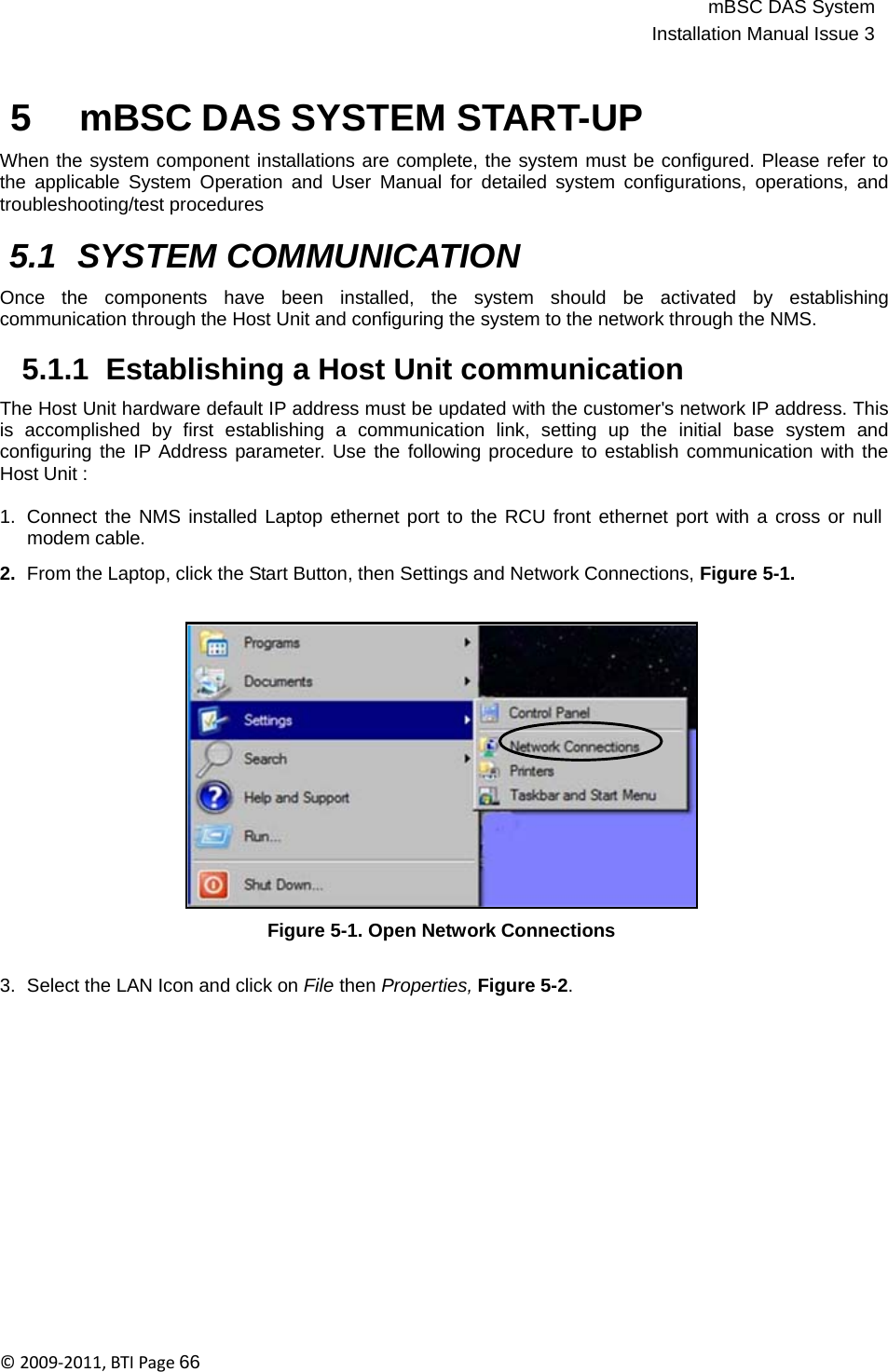
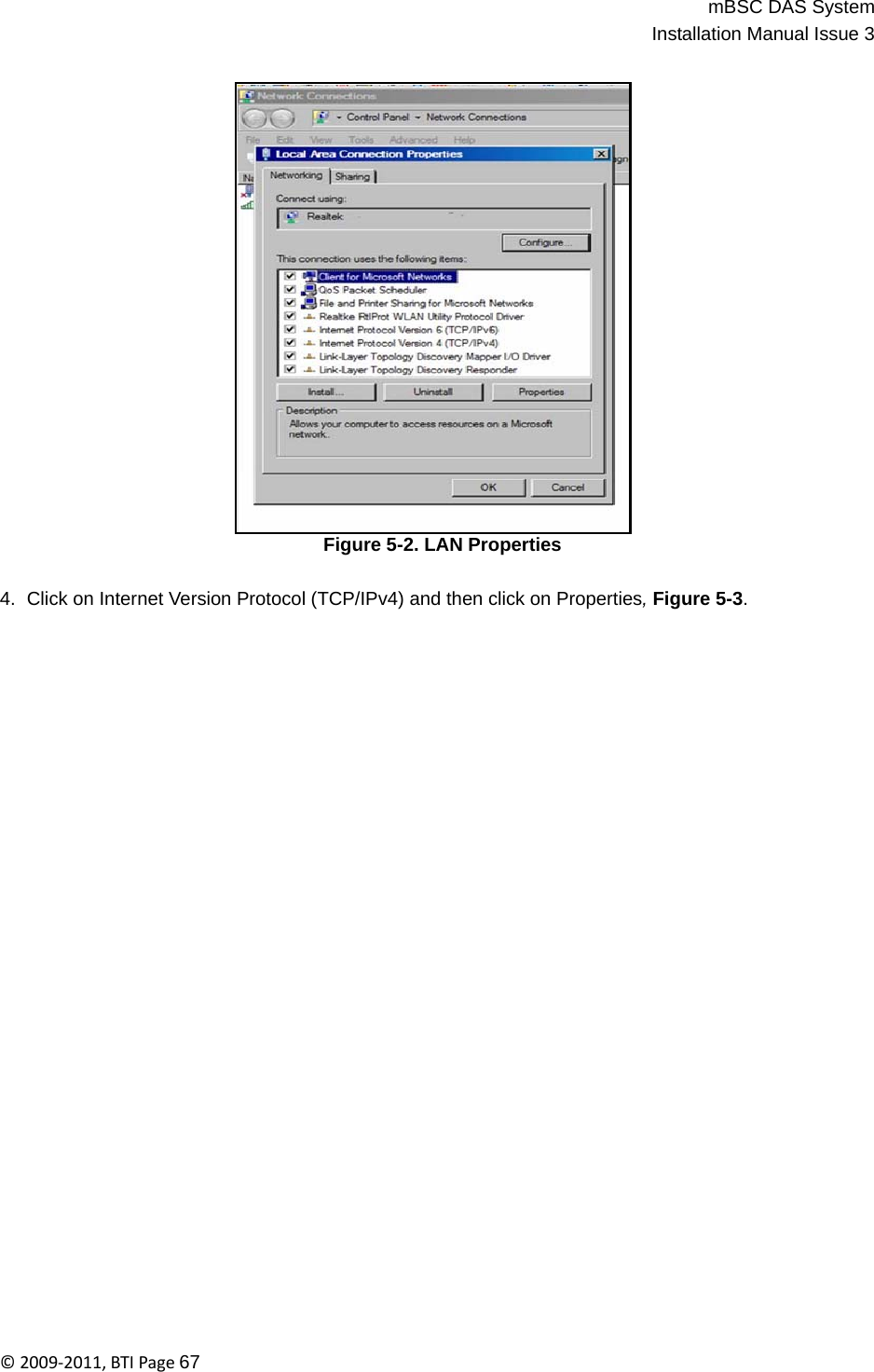
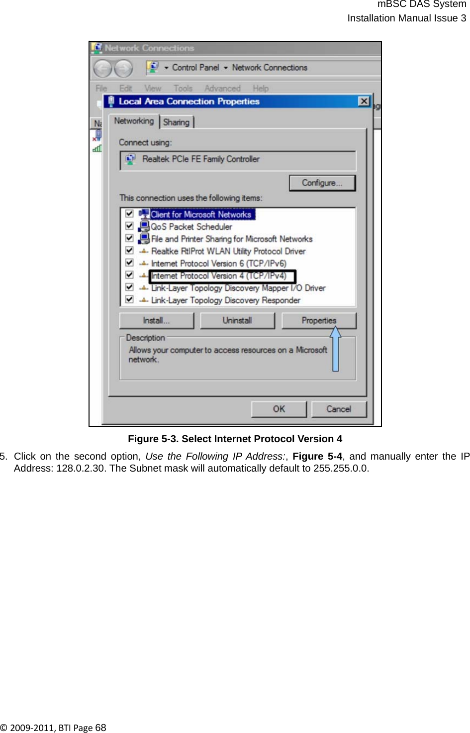
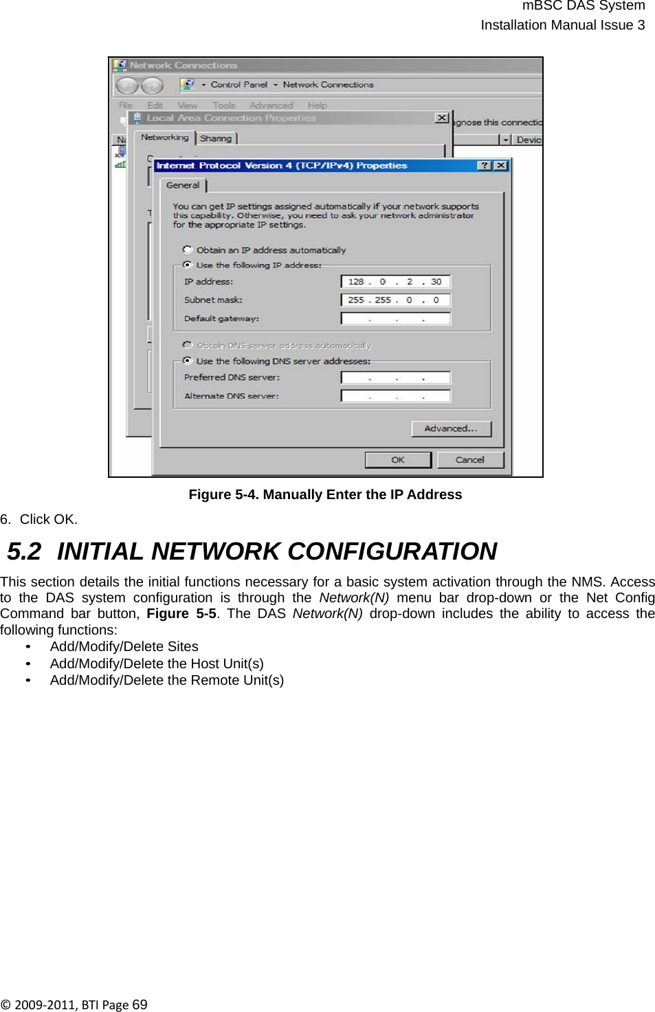
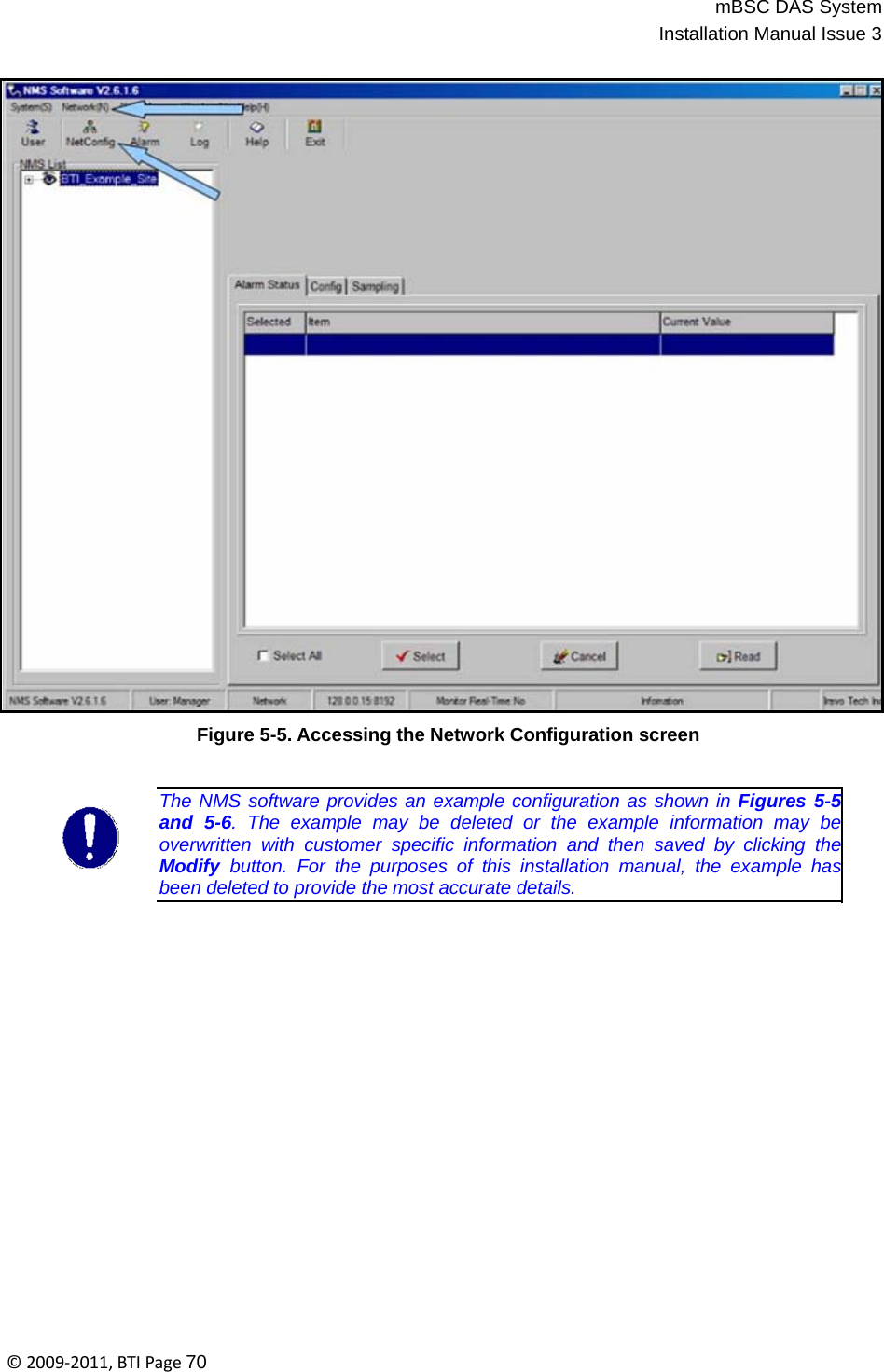
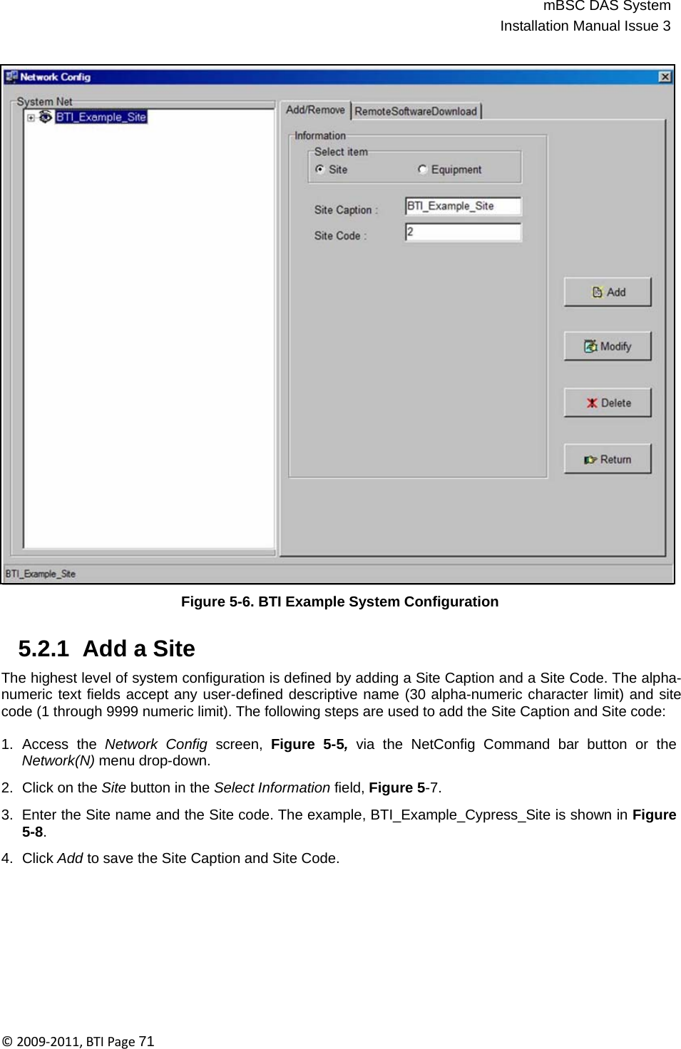
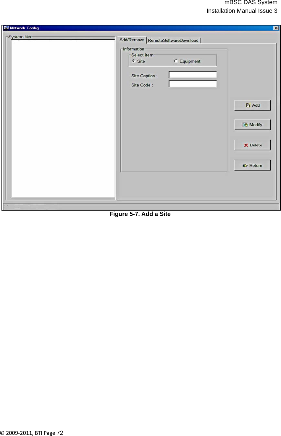
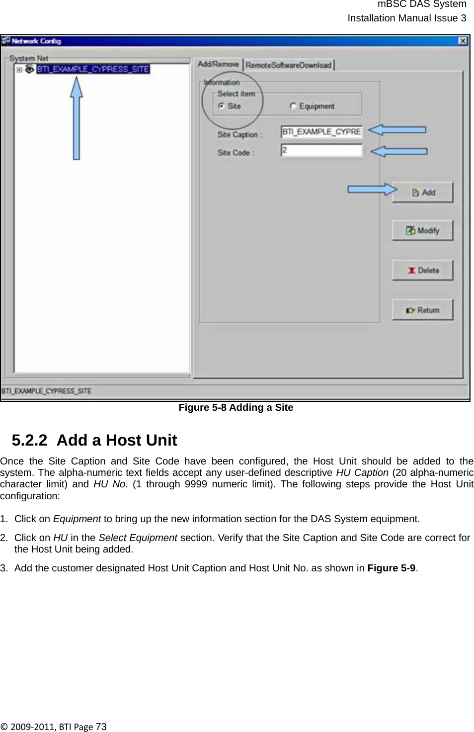
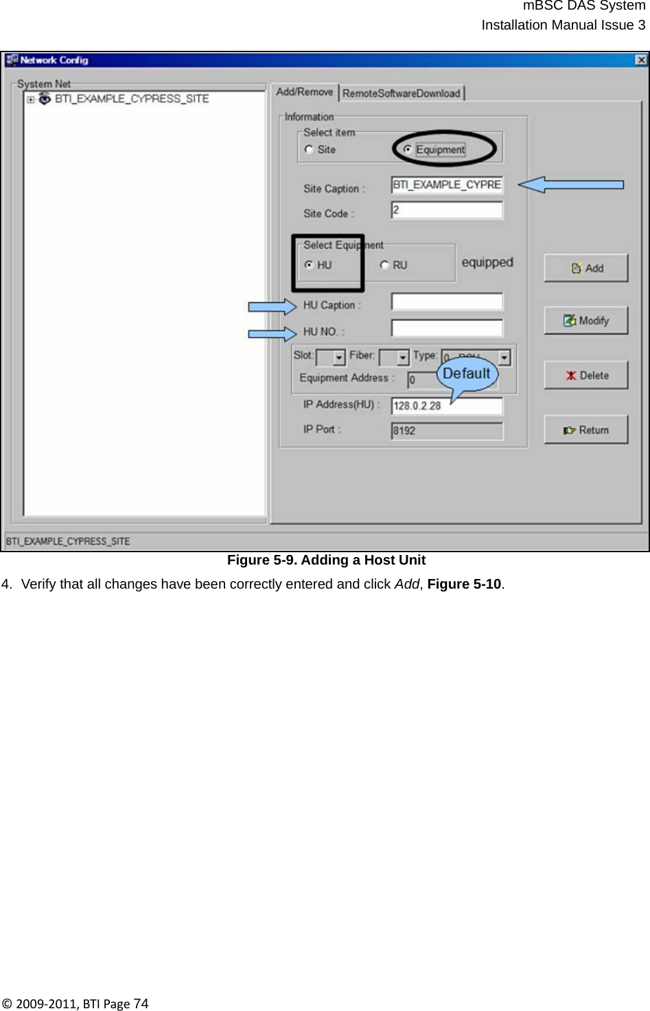
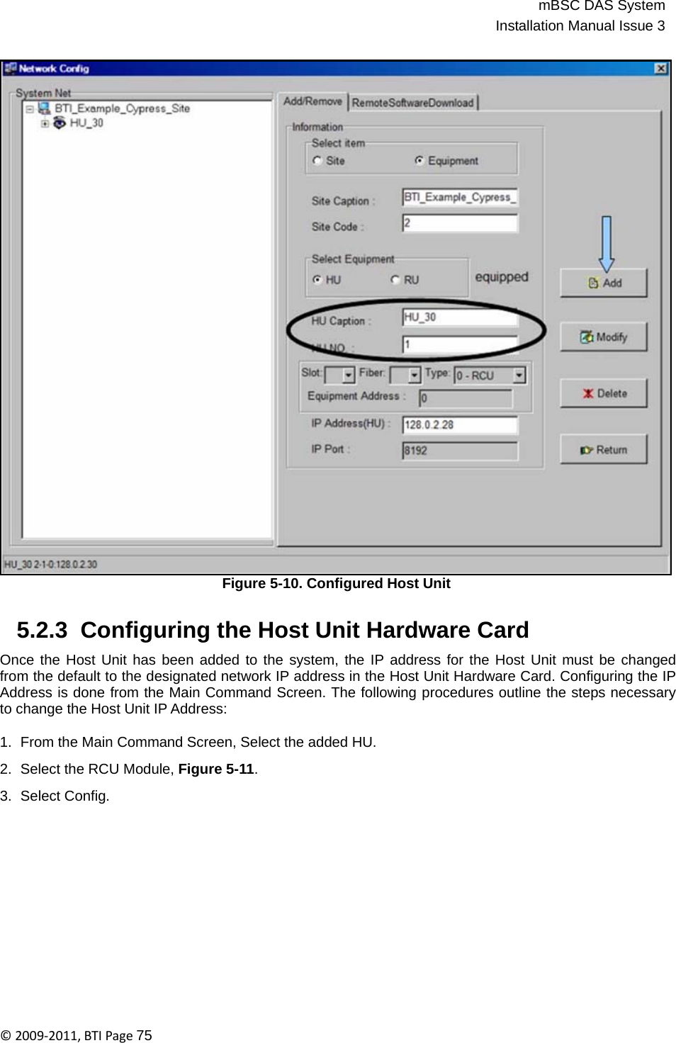
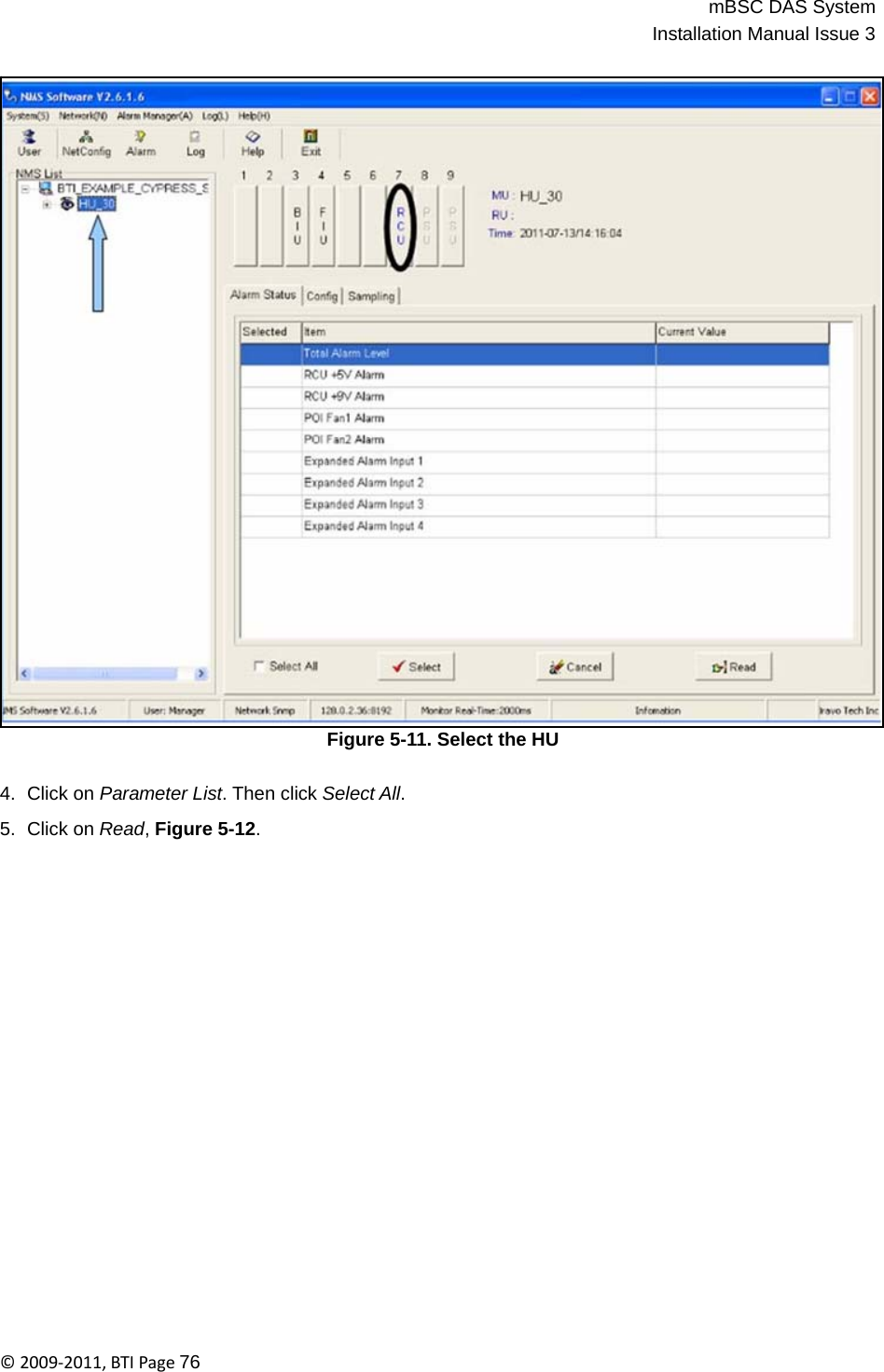
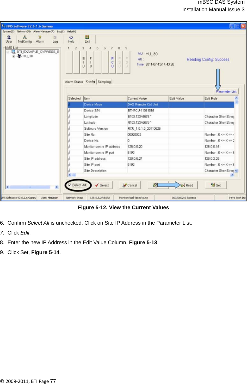
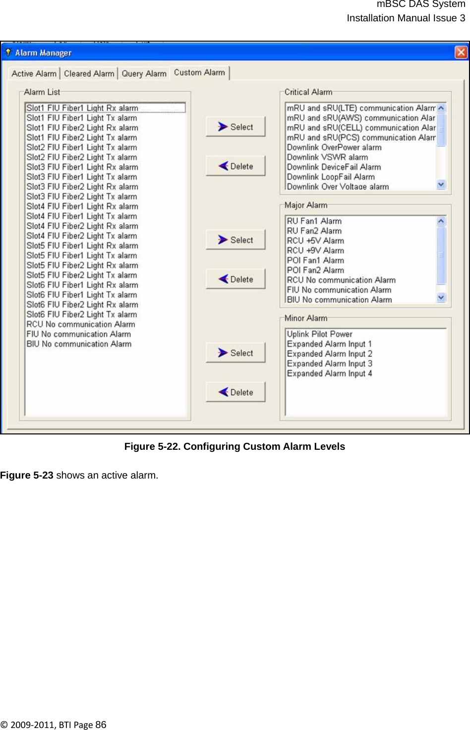
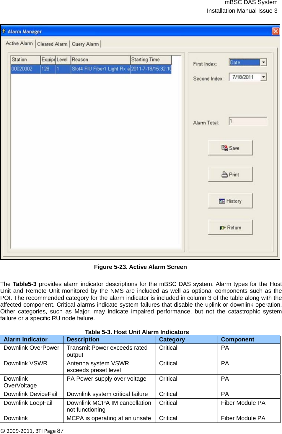
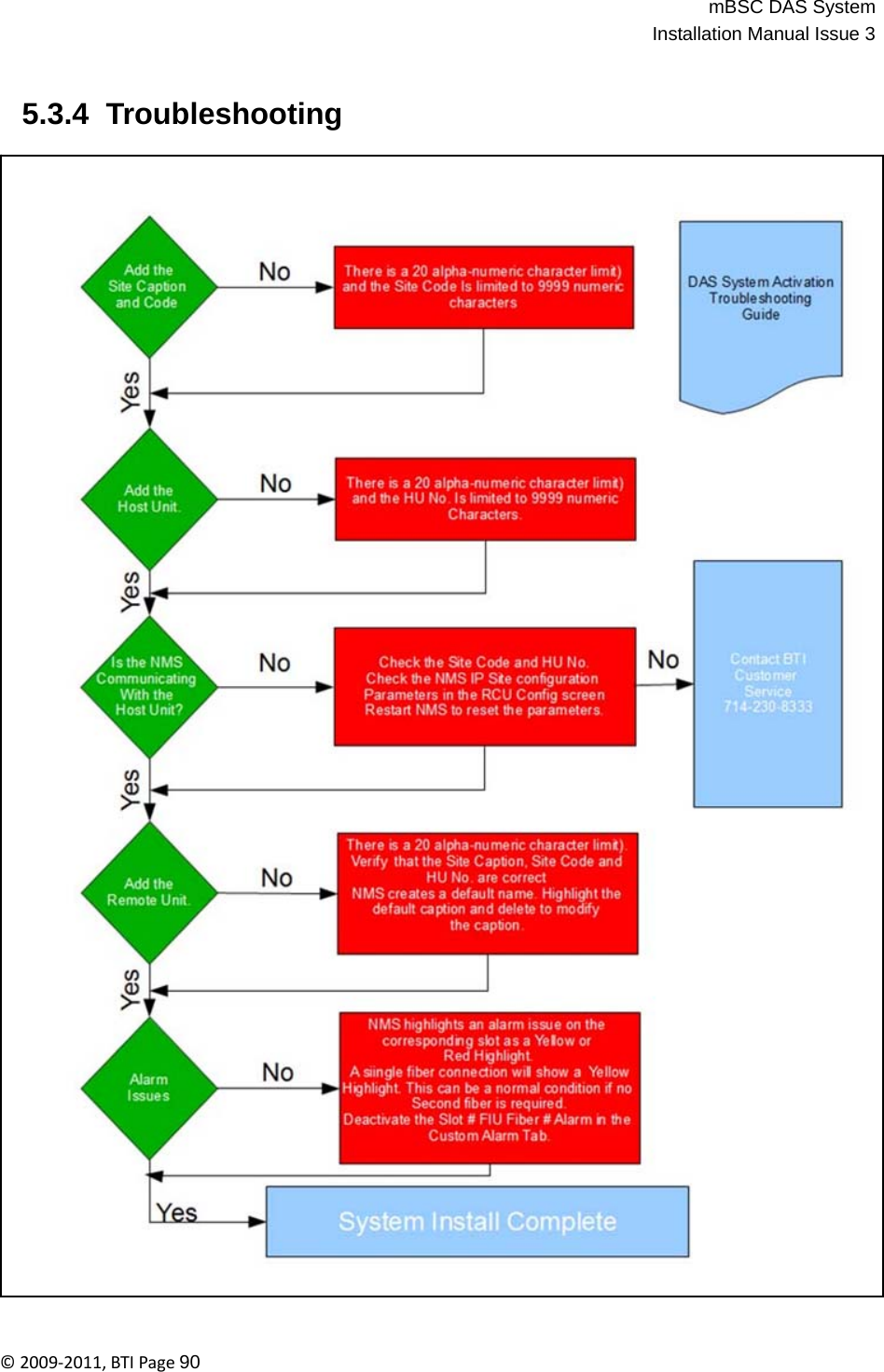
![mBSC DAS SystemInstallation Manual Issue 3©2009‐2011,BTIPage61 Figure 4-41. System Parameter Screen 4.4.7 Firmware Update DAS components periodically require firmware updates. The following list of components may require periodic firmware updates: • BIU • FIU • PA • RCU • Remote Unit A notification email is sent with the firmware update attached as a file to the email. The following procedures detail the firmware update process: 1. Verify the email is genuine and the file attachment is safe for download. The sent file will be named in the following manner and have a file extension of .s: DAS8345_[Component]_[Version].s 2. Download the attached file to any chosen folder or the desktop. Note the folder name, if saved to a designated folder.](https://usermanual.wiki/BTI-Wireless/MBSC2100-040/User-Guide-1671593-Page-62.png)