BUFFALO 000000004 11n/a&11n/g/b Concurrent Smart model; 11n/a,11n/g/b Single Smart model User Manual WAPS APG600H WAPS AG300H
BUFFALO INC. 11n/a&11n/g/b Concurrent Smart model; 11n/a,11n/g/b Single Smart model WAPS APG600H WAPS AG300H
BUFFALO >
Contents
- 1. User manual
- 2. user manual
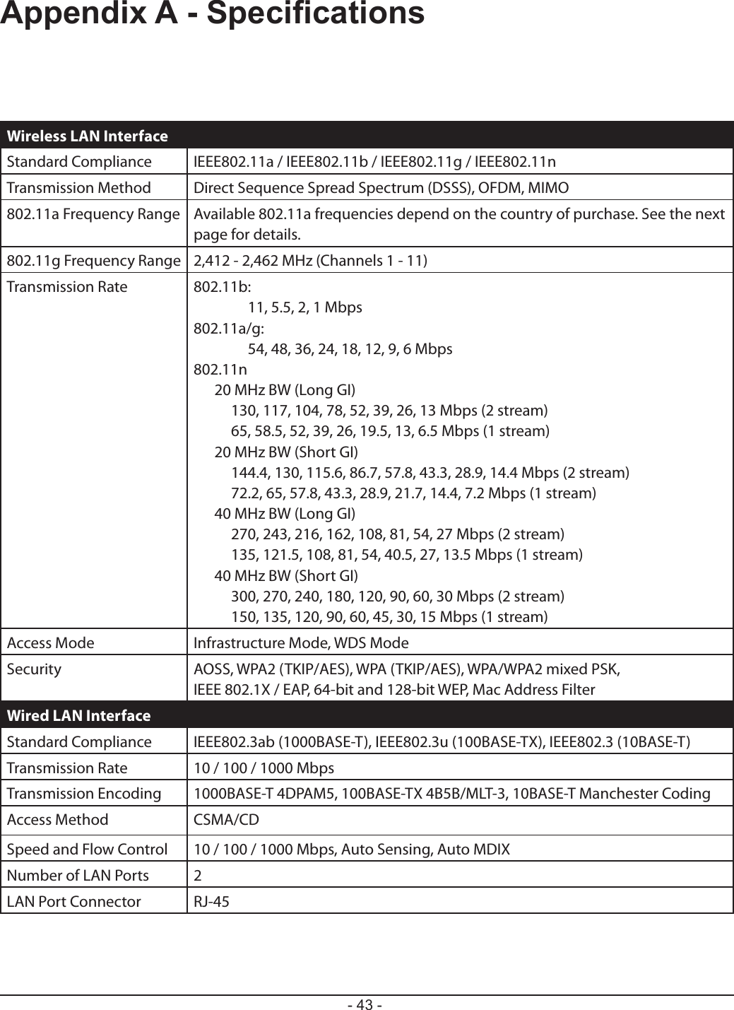
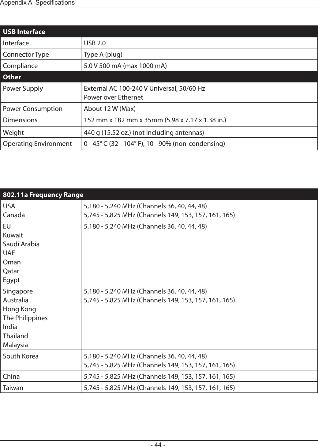
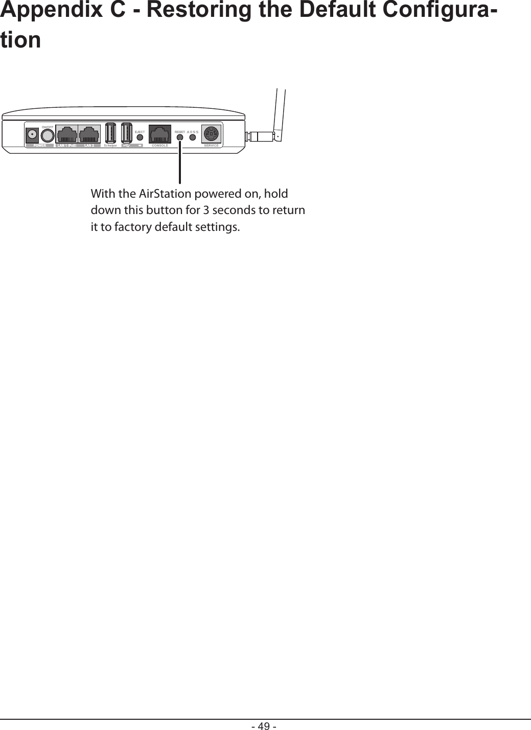
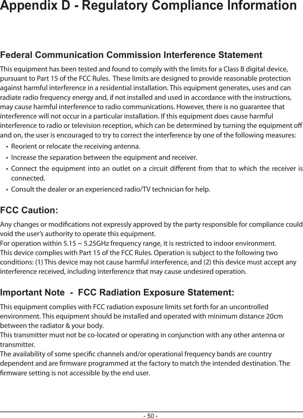
User manual
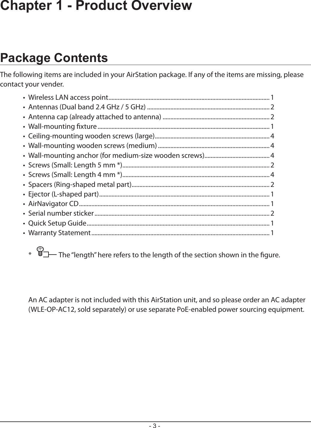
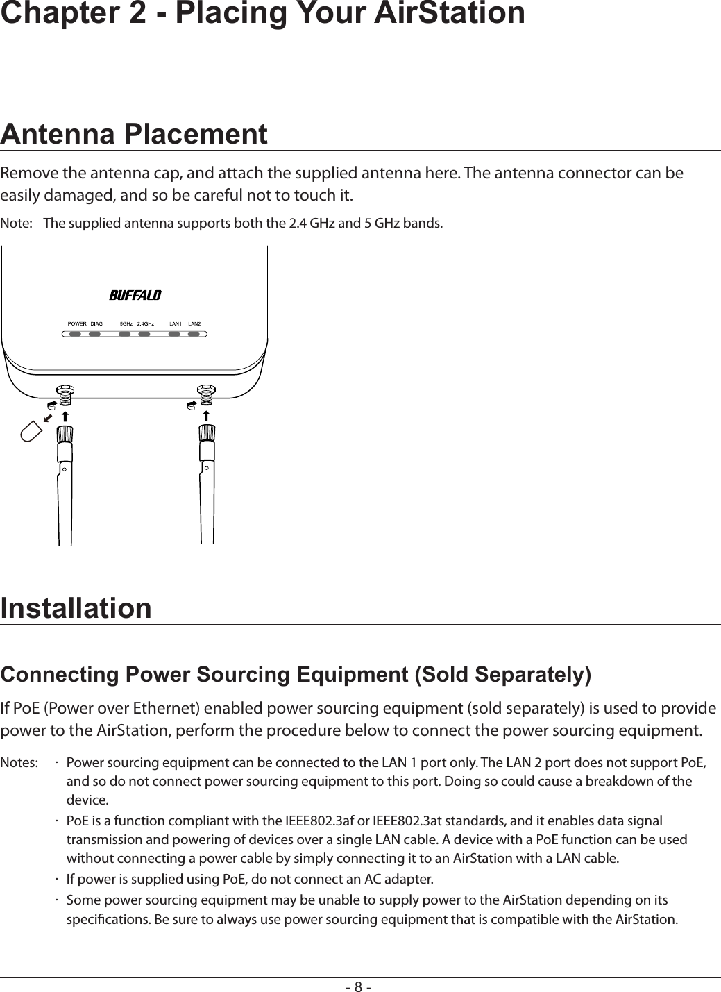
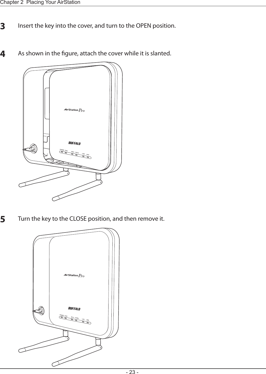
![Chapter 2 Placing Your AirStation- 11 -Initial SetupThe AirStation conguration interface can be opened for making the default settings.The AirStation Conguration Tool is used to open the setting screen. Install the AirStation Conguration Tool on your computer, and then open the AirStation conguration interface.Note: The computer that opens the setting screen must be a Windows computer with Internet Explorer 8.0 or later installed.Installing the AirStation Conguration Tool12Boot your computer and insert the AirNavigator CD. The setup wizard will launch automatically.Note: If the setup wizard is not displayed, double-click [My Computer] > CD-ROM drive icon > [AirNavi.exe].Click [Options].Click [Advanced Installation].3](https://usermanual.wiki/BUFFALO/000000004.User-manual/User-Guide-1853639-Page-12.png)
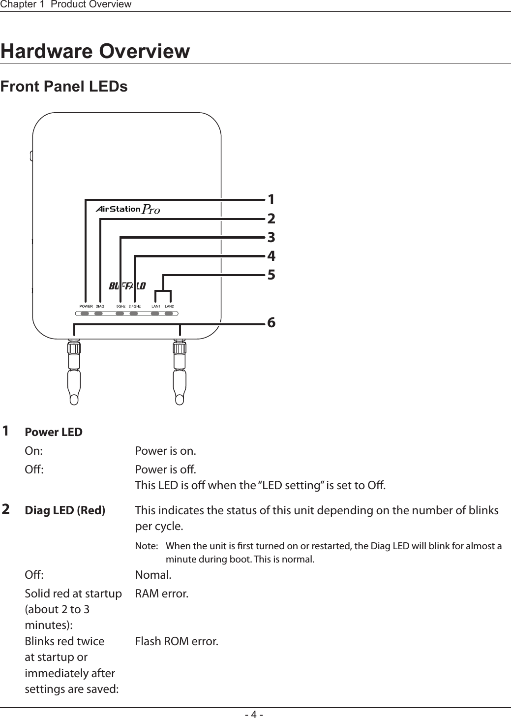
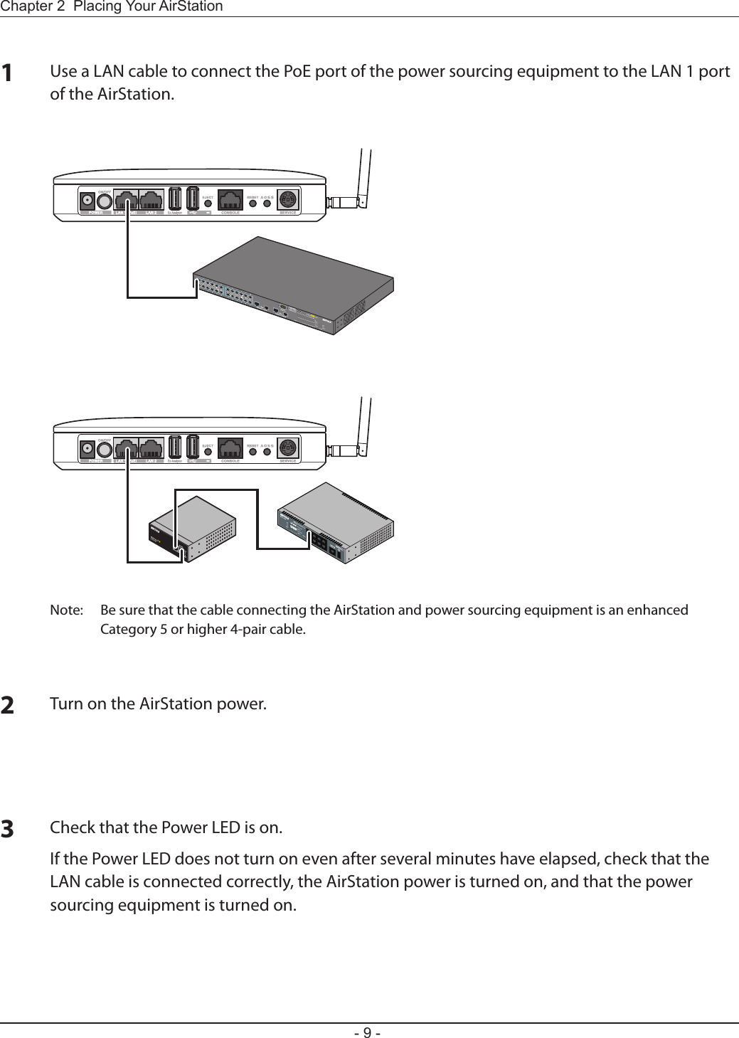
![- 12 -Chapter 2 Placing Your AirStation4Check the box for “Install AirStation Conguration Tool” and click [Install].Install by following the on-screen instructions.5Setting the AirStation IP Address1Start the AirStation Conguration Tool. Click [Start] > [All Programs]> [BUFFALO] > [AirStation Utility] > [AirStation Conguration Tool] to launch it.2Click [Next].3Highlight an AirStation to congure and click [Next].](https://usermanual.wiki/BUFFALO/000000004.User-manual/User-Guide-1853639-Page-13.png)
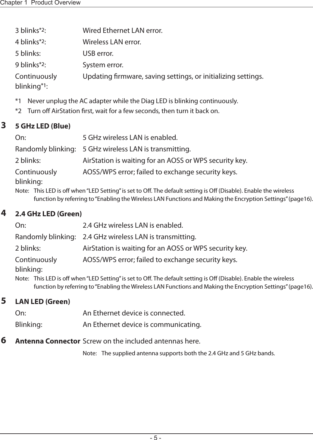
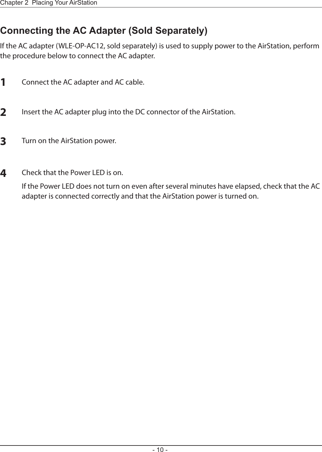
![Chapter 2 Placing Your AirStation- 13 -4Click [Congure this AirStation IP Address].5Check “Obtain IP address from DHCP server” to have DHCP obtain an IP address automatically, or you may enter IP address settings manually. Click [Next].6Enter the AirStation administrator password (the default setting is “password”), and click [Next].Note: If the AirStation administrator password is 9 characters or more, the IP address of the AirStation cannot be changed using this procedure. In this case, open the AirStation setting screen, and set the IP address.](https://usermanual.wiki/BUFFALO/000000004.User-manual/User-Guide-1853639-Page-14.png)
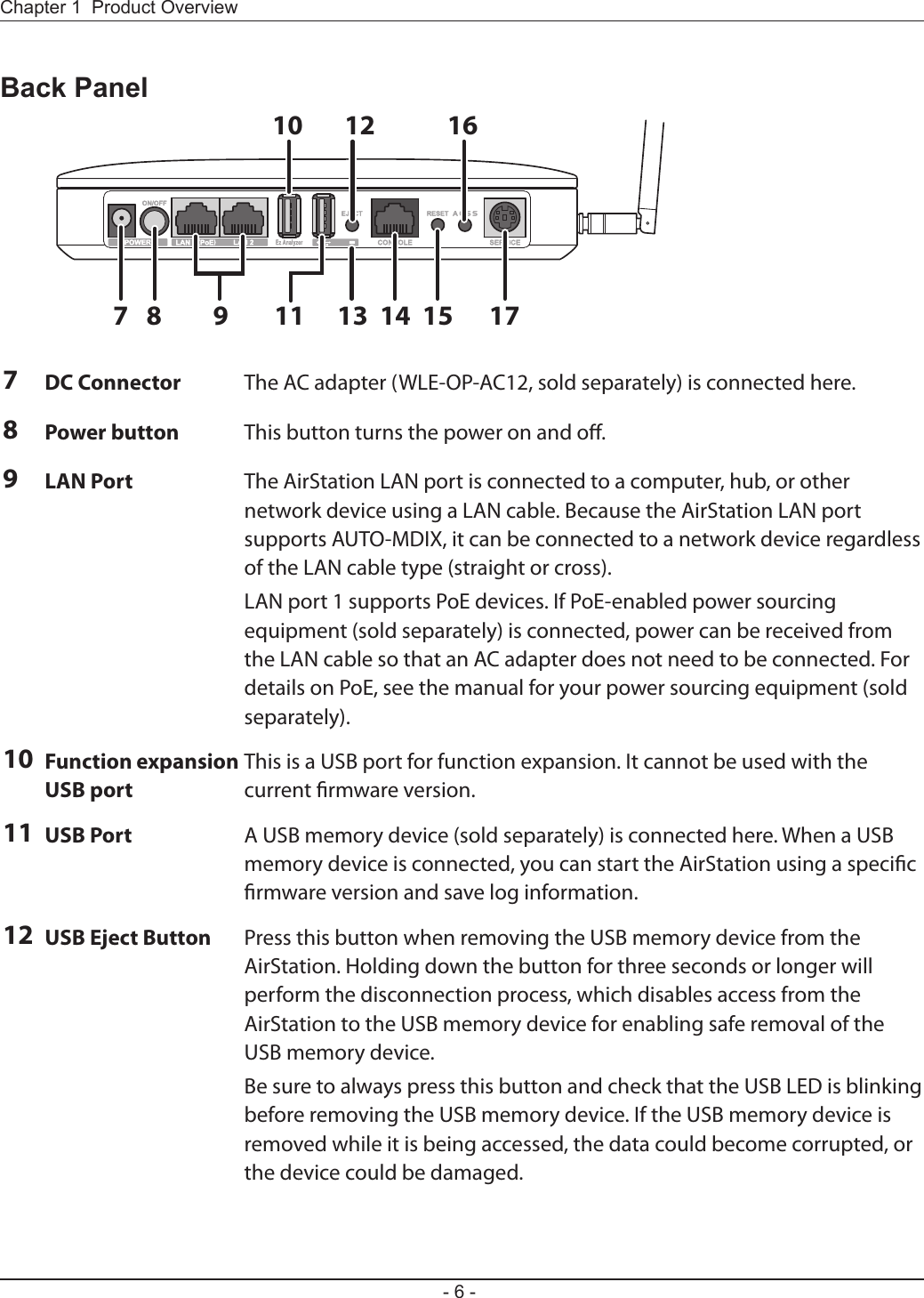
![- 14 -Chapter 2 Placing Your AirStation7Click [Finish].Accessing the Web-based Conguration Interface12Click [Next].Start the AirStation Conguration Tool. Click [Start] > [All Programs]> [BUFFALO] > [AirStation Utility] > [AirStation Conguration Tool] to launch it.](https://usermanual.wiki/BUFFALO/000000004.User-manual/User-Guide-1853639-Page-15.png)
![Chapter 2 Placing Your AirStation- 15 -3Highlight an AirStation to congure and click [Next].4Click [Open Web Setting screen.].5Click [OK].](https://usermanual.wiki/BUFFALO/000000004.User-manual/User-Guide-1853639-Page-16.png)
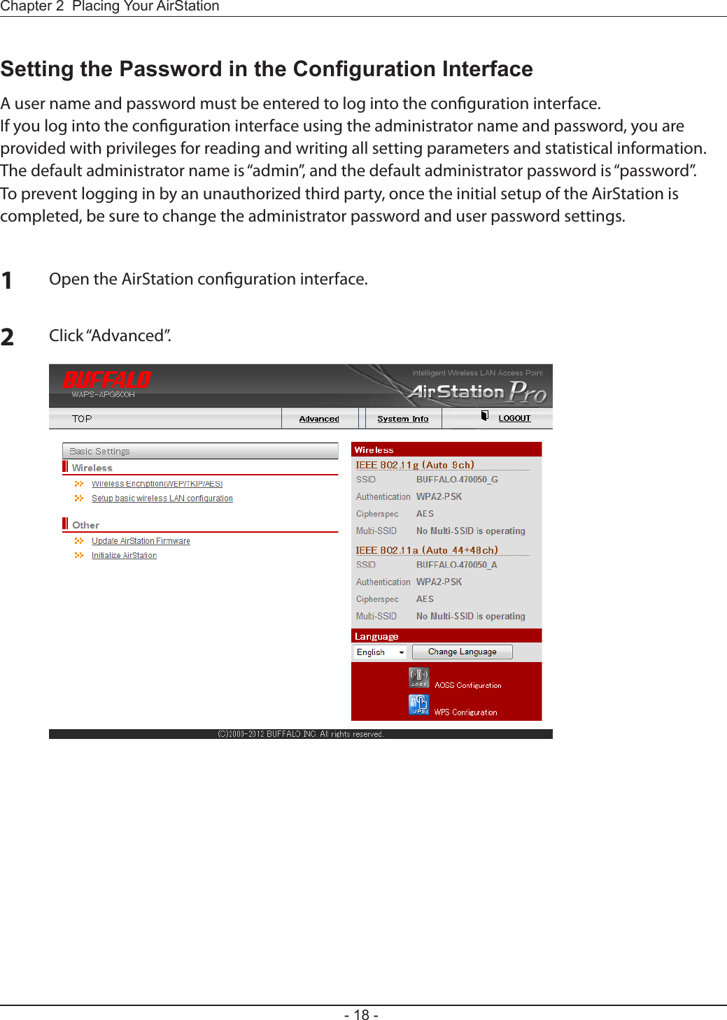
![- 16 -Chapter 2 Placing Your AirStationEnabling the Wireless LAN Functions and Making the Encryption Set-tingsIn the AirStation default state, all of the wireless LAN functions are disabled. To enable the wireless LAN functions and make the encryption settings, use the procedure below to change the settings.Note: The example in the procedure below is described when using WPA2-PSK AES for encryption.1Open the AirStation Conguration interface.2Click “Wireless Encryption(WEP/TKIP/AES)”.6When the login screen is displayed, enter “admin” for the user name, and enter “password” for the password, and then click [OK].7The AirStation Conguration Interface is displayed.](https://usermanual.wiki/BUFFALO/000000004.User-manual/User-Guide-1853639-Page-17.png)
![Chapter 2 Placing Your AirStation- 17 -3For the WAPS-APG600H, select “11a & 11g interfaces”.For the WAPS-AG300H, select “11g interface” or “11a interface”.4Select the Security Mode (example: WPA-PSK).5Select “WPA2 Only” for the WPA Type, and select “AES” for the encryption system, set the Pre-Shared Key, and click [Apply].](https://usermanual.wiki/BUFFALO/000000004.User-manual/User-Guide-1853639-Page-18.png)
![Chapter 2 Placing Your AirStation- 19 -3From the left-side menu, click “Admin Cong” > “Name / Password”.4Enter a new password for the administrator password and user password (Enter the same password again in the Conrm elds.), then click [Apply].Notes: · For the “administrator password”, enter a character string of 6 to 32 characters consisting of single-byte alphanumeric characters and symbols. · For the “user password”, enter a character string of 6 to 32 characters consisting of single-byte alphanumeric characters and symbols. · When setting the passwords, enter both the “administrator password” and “user password”. If one of these passwords is blank, the passwords cannot be set. · If you log in using the “administrator name”, all AirStation setting items can be changed. · If you log in using a “user name”, you can view all the AirStation setting values, but you cannot change them.](https://usermanual.wiki/BUFFALO/000000004.User-manual/User-Guide-1853639-Page-20.png)
![- 26 -Chapter 3 Connect to a Wireless Network 12Click [Start] > [All Programs] > [BUFFALO] > [AirStation Utility] > [Client Manager V].Windows 7/Vista (Client Manager V)If you are using Windows 7 or Vista, use the included Client Manager V software to connect wirelessly with AOSS/WPS.Click [Create Pro le].3If the User Account Control screen opens, click [Yes] or [Continue].4Click the [WPS AOSS ] button.Follow any instructions displayed on the screen. When the 2.4 GHz and 5 GHz LEDs on the front of the AirStation stop ashing and is lit steadily, the connection is complete.](https://usermanual.wiki/BUFFALO/000000004.User-manual/User-Guide-1853639-Page-27.png)
![Chapter 3 Connect to a Wireless Network - 27 -2Windows XP (Client Manager 3)If you are using Windows XP, use Client Manager 3 to connect wirelessly with AOSS/WPS.1Right click on the icon in the system tray and select [Pro le].Click the [WPS AOSS] button.It will take several seconds for your wireless connection to be con gured. When the 2.4 GHz and 5 GHz LEDs on the front of the AirStation stop ashing and glow steadily, the connection is complete.](https://usermanual.wiki/BUFFALO/000000004.User-manual/User-Guide-1853639-Page-28.png)
![- 28 -Chapter 3 Connect to a Wireless Network Mac OS X (AOSS Assistant)If you are using Mac OS X 10.7 / 10.6 / 10.5 / 10.4, use the included AOSS Assistant software to connect wirelessly with AOSS.1Load the AirNavigator CD in your Mac.2From the menu bar, click [Go] > [Computer].3Double-click the CD icon, and then double-click [AOSS Assistant] in the “Mac” folder.4The software license screen is displayed. Click [Agree] to proceed.5Click [Start AOSS ].6Enter the Mac’s username and password and click [OK].It will take several seconds for your wireless connection to be congured. When the 2.4 GHz and 5 GHz LEDs on the front of the AirStation stop ashing and glow steadily, the connection is complete.](https://usermanual.wiki/BUFFALO/000000004.User-manual/User-Guide-1853639-Page-29.png)
![Chapter 3 Connect to a Wireless Network - 29 -Manual SetupYou can also connect to the AirStation without installing Client Manager V or Client Manager 3 by using the utility built-in to Windows. The procedure varies depending on which version of Windows you are using.Windows 7 (WLAN AutoCong)With Windows 7, use WLAN AutoCong to connect to the AirStation.1Click on the network icon in the system tray.2Select the target AirStation and click [Connect]. If you will be connecting to this device in the future, checking [Connect automatically] is recommended.](https://usermanual.wiki/BUFFALO/000000004.User-manual/User-Guide-1853639-Page-30.png)
![- 30 -Chapter 3 Connect to a Wireless Network 3Enter the encryption key and click [OK]. 1Right click on the wireless network icon in the system tray.2Click [Connect to a network].When this screen is displayed, select your network and click [Connect].3Windows Vista (WLAN AutoCong)With Vista, use WLAN AutoCong to connect to the AirStation.](https://usermanual.wiki/BUFFALO/000000004.User-manual/User-Guide-1853639-Page-31.png)
![Chapter 3 Connect to a Wireless Network - 31 -If the screen below is displayed, click [I want to enter the network key or passphrase instead].Otherwise,go to step4.](https://usermanual.wiki/BUFFALO/000000004.User-manual/User-Guide-1853639-Page-32.png)
![- 32 -Chapter 3 Connect to a Wireless Network 4Enter the encryption key and click [Connect].Step through the wizard to nish conguration. If the Set Network Location screen is displayed, select [Home], [Work], or [Public location] depending on where you’re using the AirStation.](https://usermanual.wiki/BUFFALO/000000004.User-manual/User-Guide-1853639-Page-33.png)
![Chapter 3 Connect to a Wireless Network - 33 -Windows XP (Wireless Zero Conguration)Windows XP includes Wireless Zero Cong, a built-in utility to connect to your AirStation.Note: If Client Manager 3 is installed on your computer, Wireless Zero Cong is disabled. Uninstall Client Manager 3 to use Wireless Zero Cong, or just use Client Manager 3 to connect to the AirStation.1Right click on the wireless network icon in the system tray.2Click [View Available Wireless Networks].34It will take several seconds for conguration to complete.Select the network to connect to and click [Connect].Enter the encryption key (twice) and click [Connect].](https://usermanual.wiki/BUFFALO/000000004.User-manual/User-Guide-1853639-Page-34.png)
![- 34 -Chapter 3 Connect to a Wireless Network Mac OS X (Wi-Fi)Use Wi-Fi on a Mac to connect to the AirStation.Note: In Mac OS X 10.6 and earlier, “Wi-Fi” appears as “AirPort”.123It will take several seconds for conguration to complete.Click the icon in the top section of the screen and select [Turn Wi-Fi On].Find the AirStation’s SSID on the list. Click it to highlight it.Enter the KEY into the Password entry box, check [Remember this network], and click [OK].](https://usermanual.wiki/BUFFALO/000000004.User-manual/User-Guide-1853639-Page-35.png)
![- 35 -For users of Windows 7, Vista, or Mac OS X (10.4 and later), software supplied with the AirStation can be used to check the quality and strength of the wireless signal.Windows 7/VistaNote: · If Client Manager V is not already installed, install it from the AirNavigator CD. · Client Manager V does not support Windows XP.Chapter 4 - Checking Wireless Signal Quality3When the Client Manager V status screen is displayed, click .1Click the icon in the system tray.2Click [Advanced Setup].](https://usermanual.wiki/BUFFALO/000000004.User-manual/User-Guide-1853639-Page-36.png)
![- 36 -Chapter 4 Checking the Wireless Signal Quality and Strength4Parameter MeaningConnection status Signal strength (dBm), link speed (Mbps), and signal quality (%) are displayed in one-minute intervals on a real-time graph.Usage status by channel The 11b/11g display shows usage in the 2.4 GHz band channels 1 to 14.The 11a display shows usage in the W52, W53, and W56 channels.Colors are used to indicate the signal strength of the access point. Colors closer to red indicate an access point with a stronger signal strength, and colors closer to blue indicate an access point with a weaker signal strength.Mac1Load the AirNavigator CD into your Mac.2From the menu bar, click [Go] > [Computer].3Double-click the CD icon, and then double-click [WLAN Monitor] in the “Mac” folder.](https://usermanual.wiki/BUFFALO/000000004.User-manual/User-Guide-1853639-Page-37.png)
![Chapter 4 Checking the Wireless Signal Quality and Strength- 37 -4The software license screen is displayed when starting for the rst time only. Click [Agree] to proceed.5Parameter MeaningNetwork name (SSID) This displays the SSID of the AirStation that is currently connected.Status This indicates the current connection status.IP Address This indicates the IP address of the current wireless network port (Wi-Fi).Security This indicates the authentication method for the current connection target.Encryption This displays the encryption type for the current connection target.Band This displays the wireless band for the current connection target.Channel This displays the wireless channel for the current connection target.Link Speed (Mbps) This displays the current link speed.Quality (%) This displays the current signal quality.Signal Level (dBm) This indicates the strength of the current signal.](https://usermanual.wiki/BUFFALO/000000004.User-manual/User-Guide-1853639-Page-38.png)
![- 45 -Appendix B - TCP/IP SettingsWindows 7To congure TCP/IP in Windows 7, follow the procedure below.1Click [Start] > [Control Panel] > [Network and Internet].2Click [Network and Sharing Center].3Click [Change Adapter Settings] on the left side menu.4Right-click on [Local Area Connection], then click [Properties].5If the User Account Control screen opens, click [Yes] or [Continue].6Select [Internet Protocol Version 4 (TCP/IPv4)] then click [Properties].7To have DHCP set your IP address settings automatically, check [Obtain an IP address automatically] and [Obtain DNS server address automatically]. To set your IP address settings manually, enter values for each setting. Examples: If the router’s IP address is 192.168.11.1, IP address 192.168.11.80 Subnet mask 255.255.255.0 Default gateway 192.168.11.1 Preferred DNS server 192.168.11.1 Alternate DNS server blank8Click [OK].](https://usermanual.wiki/BUFFALO/000000004.User-manual/User-Guide-1853639-Page-46.png)
![- 46 -Appendix B TCP/IP SettingsWindows VistaTo congure TCP/IP in Windows Vista, follow the procedure below.1Click [Start] > [Settings] > [Control Panel].2Click [Network and Sharing Center].3Click [Manage network connections] on the left side menu. 4Right-click on [Local Area Connection], then click [Properties].5If the User Account Control screen opens, click [Yes] or [Continue].6Select [Internet Protocol Version 4 (TCP/IPv4)], then click [Properties].7To have DHCP set your IP address settings automatically, check [Obtain an IP address automatically] and [Obtain DNS server address automatically]. To set your IP address settings manually, enter values for each settings. Example: If the router’s IP address is 192.168.11.1, IP address 192.168.11.80 Subnet mask 255.255.255.0 Default gateway 192.168.11.1 Preferred DNS server 192.168.11.1 Alternate DNS server blank8Click [Close].](https://usermanual.wiki/BUFFALO/000000004.User-manual/User-Guide-1853639-Page-47.png)
![Appendix B TCP/IP Settings- 47 -Windows XPTo congure TCP/IP in Windows XP, follow the procedure below.1Click [Start] > [Settings] > [Control Panel].2Double-click [Network].3Right click on [Local Area Connection], then click [Properties].4Select [Internet Protocol (TCP/IP)], then click [Properties].5To have DHCP set your IP address settings automatically, check [Obtain an IP address automatically] and [Obtain DNS server address automatically]. To set your IP address settings manually, enter values for each setting. Examples: If the router’s IP address is 192.168.11.1, IP address 192.168.11.80 Subnet mask 255.255.255.0 Default gateway 192.168.11.1 Preferred DNS server 192.168.11.1 Alternate DNS server blank6Click [Close].](https://usermanual.wiki/BUFFALO/000000004.User-manual/User-Guide-1853639-Page-48.png)
![- 48 -Appendix B TCP/IP SettingsMac OS XTo congure TCP/IP in Mac OS X, follow the procedure below.1Click [Apple menu] > [System Preferences…].2Click [Network].3Click [Ethernet].4To have DHCP set your IP address settings automatically, select [Using DHCP] in the Congure IPv4 eld. To set your IP address settings manually, select [Manually] in the Congure IPv4 eld and enter values for each setting. Examples: If the router’s IP address is 192.168.11.1, IP Address 192.168.11.80 Subnet Mask 255.255.255.0 Router 192.168.11.1 DNS Server 192.168.11.1 Search Domains blank5Click [Apply].](https://usermanual.wiki/BUFFALO/000000004.User-manual/User-Guide-1853639-Page-49.png)
![Appendix D Regulatory Compliance Information- 53 -Česky [Czech]Bualo Technology Inc. tímto prohlašuje, že tento AirStation WAPS-APG600H / WAPS-AG300H je ve shodě se základními požadavky a dalšími příslušnými ustanoveními směrnice 1999/5/ES.Dansk [Danish]Undertegnede Bualo Technology Inc. erklærer herved, at følgende udstyr AirStation WAPS-APG600H / WAPS-AG300H overholder de væsentlige krav og øvrige relevante krav i direktiv 1999/5/EF.Deutsch [German]Hiermit erklärt Bualo Technology Inc. dass sich das Gerät AirStation WAPS-APG600H / WAPS-AG300H in Übereinstimmung mit den grundlegenden Anforderungen und den übrigen einschlägigen Bestimmungen der Richtlinie 1999/5/EG bendet.Eesti [Estonian]Käesolevaga kinnitab Bualo Technology Inc. seadme AirStation WAPS-APG600H / WAPS-AG300H vastavust direktiivi 1999/5/EÜ põhinõuetele ja nimetatud direktiivist tulenevatele teistele asjakohastele sätetele.English Hereby, Bualo Technology Inc. declares that this AirStation WAPS-APG600H / WAPS-AG300H is in compliance with the essential requirements and other relevant provisions of Directive 1999/5/EC.Español [Spanish]Por medio de la presente Bualo Technology Inc. declara que el AirStation WAPS-APG600H / WAPS-AG300H cumple con los requisitos esenciales y cualesquiera otras disposiciones aplicables o exigibles de la Directiva 1999/5/CE.Ελληνική [Greek]ΜΕ ΤΗΝ ΠΑΡΟΥΣΑ Buffalo Technology Inc. ΔΗΛΩΝΕΙ ΟΤΙ AirStation WAPS-APG600H / WAPS-AG300H ΣΥΜΜΟΡΦΩΝΕΤΑΙ ΠΡΟΣ ΤΙΣ ΟΥΣΙΩΔΕΙΣ ΑΠΑΙΤΗΣΕΙΣ ΚΑΙ ΤΙΣ ΛΟΙΠΕΣ ΣΧΕΤΙΚΕΣ ΔΙΑΤΑΞΕΙΣ ΤΗΣ ΟΔΗΓΙΑΣ 1999/5/ΕΚ.Français [French]Par la présente Buffalo Technology Inc. déclare que l’appareil AirStation WAPS-APG600H / WAPS-AG300H est conforme aux exigences essentielles et aux autres dispositions pertinentes de la directive 1999/5/CE.Italiano [Italian]Con la presente Buffalo Technology Inc. dichiara che questo AirStation WAPS-APG600H / WAPS-AG300H è conforme ai requisiti essenziali ed alle altre disposizioni pertinenti stabilite dalla direttiva 1999/5/CE.](https://usermanual.wiki/BUFFALO/000000004.User-manual/User-Guide-1853639-Page-54.png)
![- 54 -Appendix D Regulatory Compliance InformationLatviski [Latvian]Ar šo Buffalo Technology Inc. deklarē, ka AirStation WAPS-APG600H / WAPS-AG300H atbilst Direktīvas 1999/5/EK būtiskajām prasībām un citiem ar to saistītajiem noteikumiem.Lietuvių [Lithuanian]Šiuo Buffalo Technology Inc. deklaruoja, kad šis AirStation WAPS-APG600H / WAPS-AG300H atitinka esminius reikalavimus ir kitas 1999/5/EB Direktyvos nuostatas.Nederlands [Dutch]Hierbij verklaart Buffalo Technology Inc. dat het toestel AirStation WAPS-APG600H / WAPS-AG300H in overeenstemming is met de essentiële eisen en de andere relevante bepalingen van richtlijn 1999/5/EG.Malti[ Maltese]Hawnhekk, Buffalo Technology Inc. , jiddikjara li dan AirStation WAPS-APG600H / WAPS-AG300H jikkonforma mal-ħtiġijiet essenzjali u ma provvedimenti oħrajn relevanti li hemm fid-Dirrettiva 1999/5/EC.Magyar [Hungarian]Alulírott, Buffalo Technology Inc. nyilatkozom, hogy a AirStation WAPS-APG600H / WAPS-AG300H megfelel a vonatkozó alapvetõ követelményeknek és az 1999/5/EC irányelv egyéb elõírásainak.Polski [Polish]Niniejszym Buffalo Technology Inc. oświadcza, że AirStation WAPS-APG600H / WAPS-AG300H jest zgodny z zasadniczymi wymogami oraz pozostałymi stosownymi postanowieniami Dyrektywy 1999/5/EC.Português [Portuguese]Buffalo Technology Inc. declara que este AirStation WAPS-APG600H / WAPS-AG300H está conforme com os requisitos essenciais e outras disposições da Directiva 1999/5/CE.Slovensko [Slovenian]Buffalo Technology Inc. izjavlja, da je ta AirStation WAPS-APG600H / WAPS-AG300H v skladu z bistvenimi zahtevami in ostalimi relevantnimi določili direktive 1999/5/ES.Slovensky [Slovak]Buffalo Technology Inc. týmto vyhlasuje, že AirStation WAPS-APG600H / WAPS-AG300H spĺňa základné požiadavky a všetky príslušné ustanovenia Smernice 1999/5/ES.Suomi [Finnish]Buffalo Technology Inc. vakuuttaa täten että AirStation WAPS-APG600H / WAPS-AG300H tyyppinen laite on direktiivin 1999/5/EY oleellisten vaatimusten ja sitä koskevien direktiivin muiden ehtojen mukainen.](https://usermanual.wiki/BUFFALO/000000004.User-manual/User-Guide-1853639-Page-55.png)
![Appendix D Regulatory Compliance Information- 55 -Svensk [Swedish]Härmed intygar Buffalo Technology Inc. att denna AirStation WAPS-APG600H / WAPS-AG300H står I överensstämmelse med de väsentliga egenskapskrav och övriga relevanta bestämmelser som framgår av direktiv 1999/5/EG.Taiwan:SAR compliance has been established in typical laptop computer(s) with CardBus slot, and product could be used in typical laptop computer with CardBus slot. Other application like handheld PC or similar device has not been veried, may not comply with related RF exposure rules, and such use shall be prohibited.SafetyThis equipment is designed with the utmost care for the safety of those who install and use it. However, special attention must be paid to the dangers of electric shock and static electricity when working with electrical equipment. All guidelines of this manual and of the computer manufacturer must therefore be allowed at all times to ensure the safe use of the equipment.根據 NCC 低功率電波輻射性電機管制辦法:第十二條:經型式認證合格之低功率射頻電機,非經許可,公司、商號或使用者均不得擅自變更頻率、加大功率或變更原設計之特性及功能。第十四條:低功率射頻電機之使用不得影響飛航安全及干擾合法通信;經發現有干擾現象時,應立即停用,並改善至無干擾時方得繼續使用。前項合法通信,指依電信法規定作業之無線電通信。低功率射頻電機須忍受合法通信或工業、科學及醫療用電波輻射性電機設備之干擾。5.25-5.35秭赫頻帶內操作之無線資訊傳輸設備,限於室內使用。기종별 사 용 자 안 내 문B 급 기기( 가정용 정보통신기기 )이 기기는 가정용 (B 급 ) 전자파적합기기로서 주로 가정에서 사용하는 것을 목적으로 하며 , 모든지역에서 사용할 수 있습니다 .](https://usermanual.wiki/BUFFALO/000000004.User-manual/User-Guide-1853639-Page-56.png)