BUFFALO 09101457-0 Wireless LAN Router User Manual WZR HP Manual indd
BUFFALO INC. Wireless LAN Router WZR HP Manual indd
BUFFALO >
Contents
- 1. User manual part 1
- 2. User manual part 2
User manual part 1

User Manual
High Power Wireless
Broadband Router
WZR-HP-G54
www.buffalotech.com

2
Table of Contents
Introduction . . . . . . . . . . . . . . . . . . . . . . . . . . . 05
Installation / Setup . . . . . . . . . . . . . . . . . . . . . . 11
Antenna Installation. . . . . . . . . . . . . . . . . . . . . . 13
Standard Settings . . . . . . . . . . . . . . . . . . . . . . . 14
AOSS Setup . . . . . . . . . . . . . . . . . . . . . . . . . . . 23
Advanced Setup . . . . . . . . . . . . . . . . . . . . . . . . 26
LAN Settings . . . . . . . . . . . . . . . . . . . . . . . . 26
Wireless Settings . . . . . . . . . . . . . . . . . . 26
Wireless LAN Security . . . . . . . . . . . . . . 28
LAN Port . . . . . . . . . . . . . . . . . . . . . . . . 32
DHCP Server . . . . . . . . . . . . . . . . . . . . . 33
Wireless MAC Filtering . . . . . . . . . . . . . 36
Wireless Bridge (WDS) . . . . . . . . . . . . . 38
WAN Settings . . . . . . . . . . . . . . . . . . . . . . . 40
WAN Network . . . . . . . . . . . . . . . . . . . . . 43

3
Table of Contents
Network Settings. . . . . . . . . . . . . . . . . . . . . 45
Routing Setup . . . . . . . . . . . . . . . . . . . . 45
Address Translation . . . . . . . . . . . . . . . . 47
Packet Filter . . . . . . . . . . . . . . . . . . . . . . 50
Intrusion Detector . . . . . . . . . . . . . . . . . 55
UPnP . . . . . . . . . . . . . . . . . . . . . . . . . . . 57
Management . . . . . . . . . . . . . . . . . . . . . . . . 58
System Information . . . . . . . . . . . . . . . . 58
Change Password . . . . . . . . . . . . . . . . . 59
Time Setup . . . . . . . . . . . . . . . . . . . . . . 60
Traffic Information . . . . . . . . . . . . . . . . . 61
Client Monitor . . . . . . . . . . . . . . . . . . . . 62
Ping Tool . . . . . . . . . . . . . . . . . . . . . . . . 63
Log Information . . . . . . . . . . . . . . . . . . . 64
Syslog Transfer . . . . . . . . . . . . . . . . . . . 65
Save/Restore Settings . . . . . . . . . . . . . . 66
Reboot/Reload Settings . . . . . . . . . . . . . 67
Firmware Updates . . . . . . . . . . . . . . . . . 68
AOSS . . . . . . . . . . . . . . . . . . . . . . . . . . . 69

4
Table of Contents
Specifications . . . . . . . . . . . . . . . . . . . . . . . . . 71
Troubleshooting . . . . . . . . . . . . . . . . . . . . . . . . 76
Glossary . . . . . . . . . . . . . . . . . . . . . . . . . . . .84
Disclaimer . . . . . . . . . . . . . . . . . . . . . . . . . . . .90
Certifications . . . . . . . . . . . . . . . . . . . . . . . . . . 91
FCC Information . . . . . . . . . . . . . . . . . . . . . . . . 92
Warranty Information. . . . . . . . . . . . . . . . . . . . . 95
Contact Information . . . . . . . . . . . . . . . . . . . . . 96

5
AirStation High Power Wireless Broadband Router (WZR-HP-G54)
This manual introduces you to the AirStation Broadband Router, and will help you connect to your
network quickly.
The WZR-HP-G54 router is a wireless 4-port router network device that complies with the 2.4GHz
IEEE 802.11g standard specification for wireless LANs. It also supports 125* High-Speed Mode
technology. The WZR-HP-G54 supports enhanced built-in NAT/SPI firewall functions and is used
as a multi-functional router/link between wired and wireless LAN computers.
Summary of AirStation WZR-HP-G54 features:
• Wi-Fi™ (Wireless Fidelity) certified by the Wi-Fi Alliance as an 802.11b/g device. AirStation will
communicate with other IEEE 802.11b/g Wi-Fi compliant wireless LAN products.
• High-power amplified radio increases range by up tp 70% and performance by up to 50%.
• Supports 125* High-Speed Mode.
• Support for Wi-Fi Protected Access™ (WPA), 802.1x, TKIP, AES, and WEP.
• Supports Frame Bursting for enhanced performance.
• DHCP client/server function.
• Auto roaming supports seamless roaming over multiple channels.
• VPN pass-through for secure communications.
• Packet Filtering for eliminating unwanted communications.
• SOHO/SMB routing and firewall functions provide a safer private networking environment,
Introduction

6
including support for MS NetMeeting and MSN-Messenger.
• Additional SPI Firewall Functions: DMZ, intrusion detection, and notification.
• Syslog transmits some or all system activities to a central Syslog server.
• Extended range with optional add-on antennas or WDS (Wireless Distribution System).
• Auto Media Dependent Interface/Crossover (MDI/X) port allows connection by standard and
crossover CAT5 cables.
• Supports Universal Plug and Play (UPnP).
• Includes Buffalo’s AOSS System for easy, secure wireless client configuration.
• Enhanced security features:
- SPI Firewall and DMZ zone functions to prevent unknown intruders.
- Intrusion Detector Firewall (NAT) with pop-up or email alerts when intrusions are detected.
- Dynamic packet filtering.
- WPA, 802.1x, TKIP, AES, and WEP.
- VPN (IPSec, PPTP and L2TP) pass-through
- Packet monitoring and filtering by MAC address, IP address and port.
- PPPoE support
- WDS support
• Buffalo’s easy web-based configuration interface.
• Broadband router static and dynamic routing methods between WAN and LAN based on updated
Introduction
7
routing tables. An economical way to bridge multiple networks.
• Optional external antennas for boosting range and signal quality.
• Buffalo’s AOSS System for easy, secure wireless client configuration.
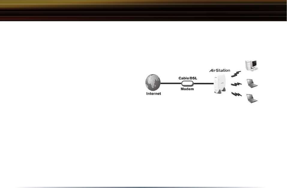
Home Networking 1
Buffalo AirStation wireless access points enable
sharing broadband by simply connecting the
AirStation to a DSL or Cable modem to:
• Share files and printers.
• Access and share the Internet.
• Share media files.
SOHO/SMB Networking
With high speed DSL or Cable connections readily available, many users can work effectively from
a home office, connected securely to a corporate network. Buffalo’s solutions are ideal for home
networks that require secure, high speed access to the corporate LAN. They include VPN con-
nectivity for secure access to corporate resources, which enables remote employees to handle
information from clients or coworkers as if they were in the office. Connect the Buffalo AirStation
Broadband router AP to a Cable or DSL modem in order to:
•Share broadband access.
•Share files and printers.
•Bridge between multiple networks and multiple computer platforms.
Introduction

8
•Provide easy and secure access to home or company networks from remote locations.
System Requirements
• Broadband (High Speed) Internet connection or existing Local area connection.
• Wi-Fi (wireless) compatible computer with a Web Browser (such as Internet Explorer or Netscape)
of version 4.5 or later. Safari 1.0 is supported with Macintosh OS X 10.2 or later.
AirStation WZR-HP-G54 Package Contents
The AirStation WZR-HP-G54 package consists of the following items:
• WZR-HP-G54 AirStation
• AC adapter and power cable
• CAT5 LAN cable
• Utility CD with Manual
• Quick Setup Guides
• Warranty Statement
Introduction
9
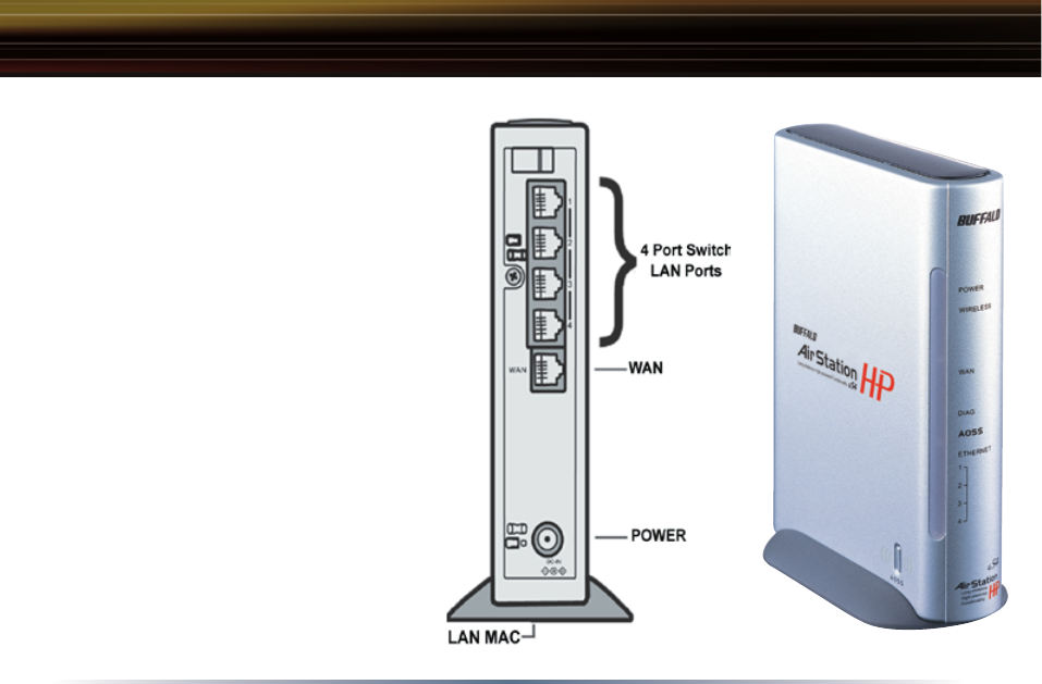
Product Views
Power - Lit when the device is powered on.
Wireless - Lit when the wireless radio is on.
Flashes when wireless traffic is present.
WAN - Lit when connection to Cable/DSL
modem is present. Flashes when internet
traffic is present.
Diag - Flashes red when performing
diagnostic functions.
AOSS - Flashes when in AOSS mode, solid
when AOSS encryption has been set.
Ethernet - 1, 2, 3, or 4 lit when ethernet
clients are connected. Flashes when
ethernet traffic is present.
Introduction

10
About the AirStation CD
The AirStation does not require any software to be installed on your computer for configuration.
The AirStation CD contains client drivers for Buffalo Wireless Adapters (i.e. Notebook Adapter and
Desktop PCI Adapter) and the AirStation documentation.
Prior to copying or installing any software, please read the Software License Agreement “license.
txt”, located in the root folder of the CD. By installing, copying or using the AirStation software, you
are consenting to the terms of this agreement. If you do not agree to all of the terms of the Software
License Agreement, do not download, copy or install the AirStation software.
It is the policy of Buffalo Technology to improve products as new technology, components, software
and firmware become available.
Please consult the Buffalo Technology website (http://www.buffalotech.com) to download and install
the latest firmware for your product.
Introduction
11
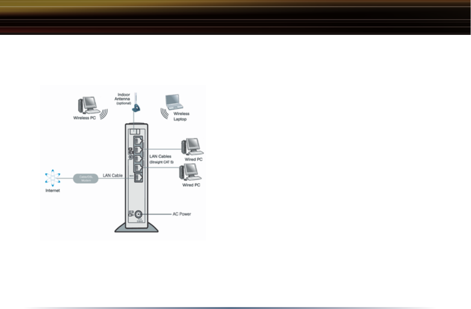
Follow these simple steps to connect the AirStation to your Broadband Internet connection allowing
you to combine and share wired and wireless computers and printers with the high speed internet
connection.
1. Power down the Cable or DSL modem and
the computer which will be used to configure the
AirStation router.
2. Plug the Cable or DSL modem’s LAN Ethernet
cable into the AirStation’s WAN port. You may
need to unplug this cable from your computer, hub
or other router.
3. Plug the provided Ethernet cable into a LAN
port on the AirStation and plug the other end into
your computer Ethernet adapter’s (NIC) port. If
you plan to initially configure the AirStation via a
wireless connection (not recommended), you may
skip this step.
4. Power on your cable or DSL modem and wait
one full minute. Power on the AirStation router, wait another full minute and then power on the
computer which will be used to configure the AirStation. If the red DIAG light on the AirStation is
lit or flashing after several minutes of being powered on, please consult Buffalo Technical Sup-
port.
Installation / Setup

12
Introduction
Configuring the AirStation using a standard web browser requires basic wireless configuration
knowledge. Setup includes manual wireless configuration and basic administrative management.
Setup Preparation
Make note of the AirStation’s LAN MAC address (found on the underside of the WZR-HP-G54). It
is also recommended that you record any other broadband ISP information, such as global IP ad-
dress, subnet mask address, default gateway address, DNS server address and PPPoE param-
eters.
Setup Overview
Buffalo recommends using a wired connection, meaning your computer is physically connected
to the AirStation with a CAT5 cable plugged into one of the four LAN ports This type of setup will
eliminate possible setup problems due to any issues with the wireless adapter on the computer be-
ing used to configure the AirStation.
Installation / Setup

13
The WZR-HP-G54 has two internal antennas. One has a
vertical orientation while the other has a horizontal orienta-
tion. This setup is ideal because it allows for proper antenna
polarization with both desktop and notebook style wireless
adapter antennas.
However, it may be necessary to increase your range further
by installing an external, higher-gain antenna. Available ex-
ternal antennas are described as below. Antennas also come
with different connectors. The WZR-HP-G54 has an unique
‘MC Connector’ on it. Thus, the antenna must also have an
MC connector.
The following four antennas are allowed to connect to WZR-
HP-G54.
WLE-DA: Patch Antenna
WLE-NDR: Sleeve Antenna
WLE-HG-NDR Sleeve Antenna
WLE-MYG Yagi Antenna
Antenna Installation
14
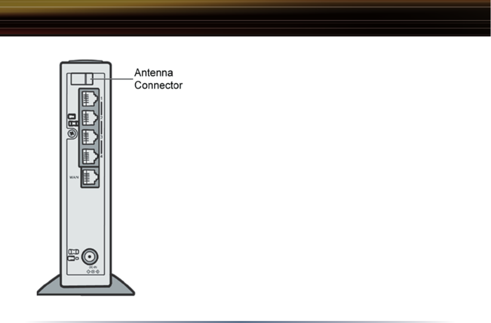
Antenna Installation
To install the antenna, slide the antenna connector door on
the back of the WZR-HP-G54 to the right. This will expose
the MC Connector. Attaching the antenna is simple; just in-
sert the antenna’s MC Connector into the WZR-HP-G54’s MC
Connector and firmly push it in until it snaps into place. Once
clicked into place, the antenna’s connector should swivel
easily. It is important not to push the antenna connector in at
an angle.
To remove the antenna, pull the antenna connector out. It is
important not to pull the antenna connector out at an angle.
14
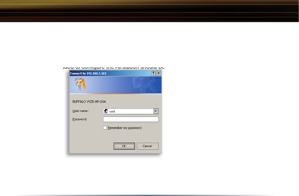
Open the Setup Screen
The computer used to confi gure the Airstation should be set to ‘obtain an IP address automatically
using a DHCP server’. Connect it to one
of the four ports on the WZR-HP-G54
with an ethernet cable. On the computer,
launch a Web Browser of version 4.5 or
later. Enter 192.168.11.1 into the URL
fi eld. A window will open prompting you
to enter a User ID and Password. Enter
“root” as the User ID and leave the pass-
word fi eld blank. Click OK to log in to the
Airstation.
■ NOTE: The WZR-HP-G54 has a default
IP address of 192.168.11.1 and a Subnet
Mask of 255.255.255.0.
The computer used to confi gure the Airstation should be set to ‘obtain an IP address automatically
Initial
Settings
Login
Standard Settings
15
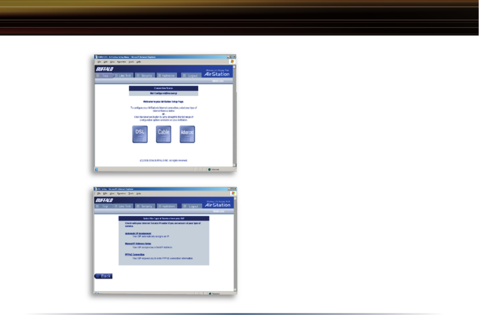
Enter ISP information
Click the appropriate button to select the type
of broadband you have. Users experienced in
networking may choose to select the Advanced
button and skip to Section 4. For supplementary
tools, use the tabs along the top of the screen.
DSL Button
Select this if you have a dsl modem. If you have
a cable modem, skip to page 17.
Automatic IP Assignment by ISP
The DHCP server of the ISP assigns an IP ad-
dress automatically.
Initial
Settings
Screen
Initial DSL
button
Screen
Standard Settings
16
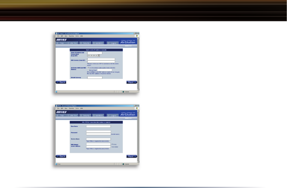
Enter IP Address Manually
Enter the IP Address given by your ISP here if
they require the use of a static IP address.
PPPoE Connection
Enter the PPPoE information provided by your
ISP.
Manual DSL
IP Settings
Screen
DSL PPPoE
Settings
Screen
Standard Settings
17
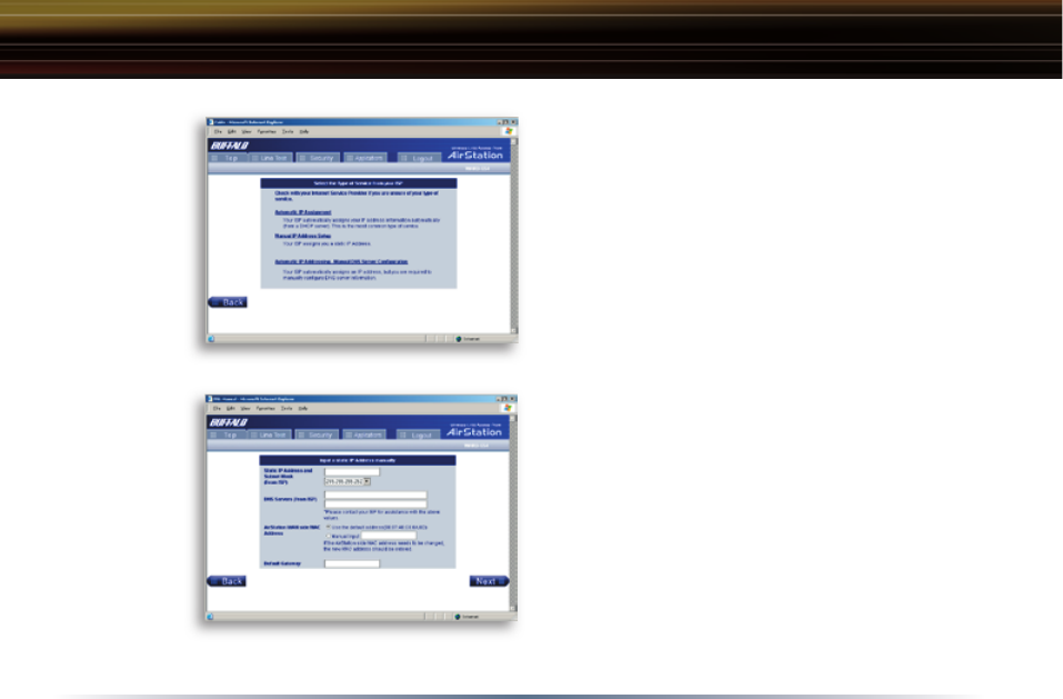
CATV (Cable) Button
Press this if your internet connection is via a
cablemodem.
Automatic IP Assignment by ISP
Select ‘Automatic IP Assignment by ISP’ if
your ISP’s DHCP server assigns an IP address
automatically.
Enter IP Address Manually
Select ‘Enter IP Address Manually’ if your ISP
requires the use of a static IP address.
Initial CATV
Settings
Screen
Manual IP
Address
Settings
Standard Settings
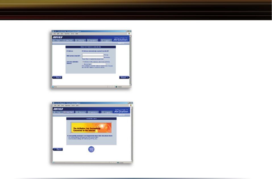
18
The IP Address is Acquired
Au to mat i cal ly but DNS Server Address
is Entered Manually
Select ‘IP address is acquired automatically but
DNS server address is entered manually’ if the
ISP’s DHCP server supplies an IP address but
not DNS server addresses.
Line Test
Tests the connection to the Internet.
Auto IP/
Manual DNS
Settings
Line
Test Tab
Standard Settings

19
Security
The Security Tab offers three simple security
settings. Follow the in struc tions in each screen
to enter Encryption Keys, MAC Address Filter-
ing and the degree of fi rewall security for the
AirStation.
Security Tab
Standard Settings
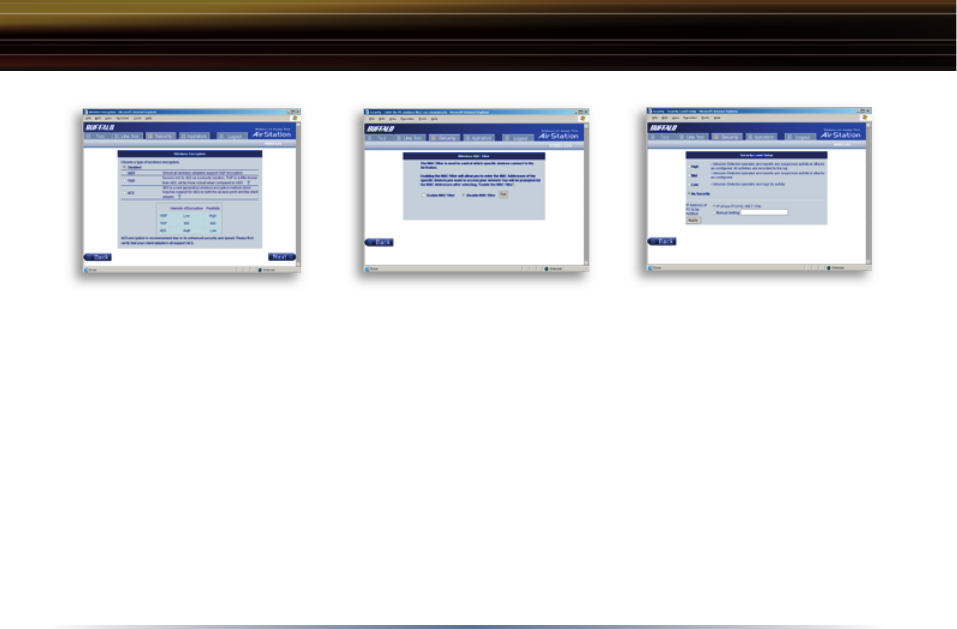
20
Encryption Setup.
- Select the desired encryption
scheme from the choices. After
it has been selected, press the
‘Next’ button. You will then be
prompted to enter the appropriate
key(s) for that method of encryp-
tion.
Simple MAC Address Filter.
- Select ‘Enable’ to use MAC
fi ltering. See page 36 for more
information on MAC Address
Filtering.
Simple Security Setup.
- See page 55 for more information on
Intrusion Detector.
Standard Settings
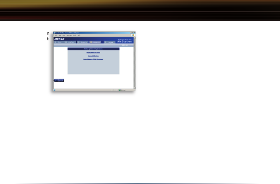
21
Applications
The Application Tab offers setup for special ap-
plications such as games, MS NetMeeting and
MSN Messenger. Follow the on-screen menus
to confi gure the AirStation for the application.
Ap pli ca tion
Tab
Ap pli ca tion
Tab
Standard Settings
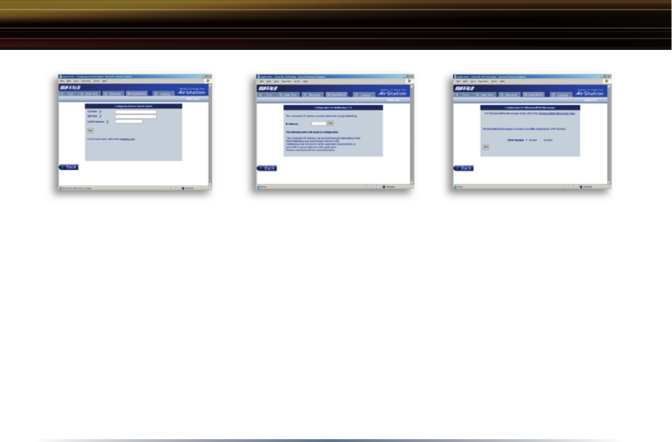
22
Internet Gaming Setup:
Enter the ports (refer to Game
documentation) that the game
uses and enter the Local IP
Address of the PC that plays
the game.
NetMeeting Setup:
Enter the IP Address of the PC
that will use Netmeeting.
MSN Messenger Setup:
Refer to the on-screen help for
information about Messenger.
Standard Settings
Although your AirStation will function fi ne using only the Standard Settings, you may wish to
explore more advanced options. The Advanced Settings section explains each function in the
Advanced settings area.
Click the Top tab and click the Advanced button to enter the Advanced settings area.
23
AOSS
AOSS (AirStation One-Touch Secure System) is a simple, one-touch setup for connecting wireless
clients to an access point while setting up the most secure possible connection. Users no longer
need to worry about choosing the proper security protocols, IP addresses, or SSID's. The
intelligence of AOSS determines the most optimal connection and configures itself in seconds.
■ NOTE: AOSS automatically creates a secure connection between your AOSS Access Point and
client. You must have a Buffalo AOSS enabled wireless client device to use the AOSS features of
your AOSS Access Point/Router.
◗ Configure your WZR-HP-G54’s internet
connection by referring to the instructions
in the WZR-HP-G54 Quick Setup Guide.
◗ Once the WZR-HP-G54 has been config-
ured, follow the directions to install your
wireless client device and its drivers if
necessary. Certain wireless client adapt-
ers require client software to configure
them. If your device has a Client Man-
ager, install it as well.
■ NOTE: If the wireless client adapter is
installed on a PC, then the AOSS client
manager will need to be installed as well. If your wireless client adapter is a standalone device that
does not require a PC, then just power up the device.
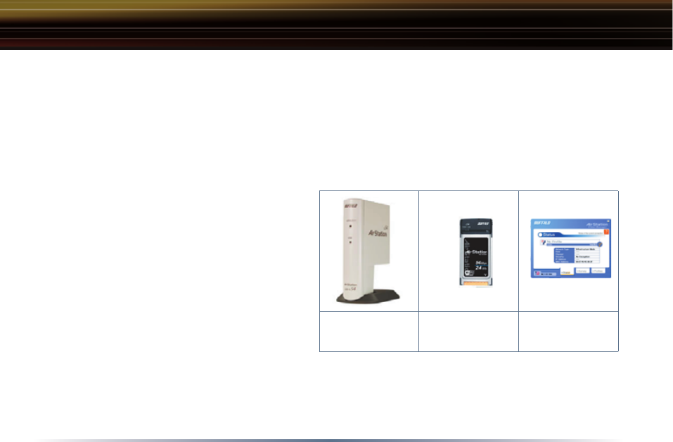
Standalone Devices: Ethernet Converters and Access Point Bridges
Client Manager Devices: CardBus, USB, and PCI Adapters.
Standalone
AOSS Device
Client Manager
Device
Client Manager
Software

24
◗ Now that the WZR-HP-G54 and wireless client adapter
are installed, you can use AOSS to confi gure them.
◗ To begin the confi guration, press the AOSS button on
the side of the WZR-HP-G54 for 3-5 seconds. The AOSS
light will begin to fl ash when the AOSS mode has been
enabled. You can stop pressing the button at this point.
■ NOTE: AOSS mode will stay active for a period of two
minutes. This is the time-slot for initiating the wireless
client adapter. The AOSS LED will stop fl ashing when
AOSS mode has stopped or timed out.
◗ Refer to your wireless client adapter's AOSS
supplement to initiate the wireless client adapter's AOSS
mode.
◗ It typically takes 10-15 seconds for the AOSS light to
stop fl ashing after the AOSS button has been pressed
on the wireless client adapter. Once confi guration is
complete, the AOSS light will remain steady. Please
refer to your wireless client adapter's supplement for the
remainder of the setup.
AOSS

25
Additional AOSS Information:
◗ Only one AOSS wireless client adapter can be configured to the AOSS router at a time. Thus,
the button will need to be repressed for each additional AOSS wireless client adapter that will be
connected.
◗ It is not necessary to AOSS client devices that have already been configured via AOSS unless
significant changes have been made to the wireless network.
◗ Do not attempt to configure two separate AOSS networks at the same time, as it may cause
undesired configurations.
◗ If an undesired client has connected via AOSS, it can be disconnected from within the WZR-HP-
G54’s advanced configuration menus.
AOSS
26
LAN Settings
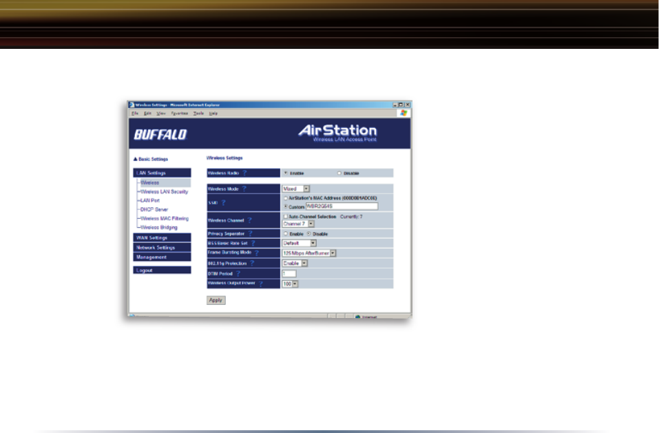
Wireless Settings
Wireless Function - Enable or
disable wireless LAN computer
communication.
SSID - Allows administrator to
alter the SSID of the AirSta-
tion. Once this is done, the
AP’s new SSID should be se-
lected in the client computer’s
wireless settings. The client
computer then looks for that
specifi c AP (and SSID) for wire-
less communication. Use up
to 32 al pha nu mer ic characters for the SSID (case sensitive). By default the SSID is the LAN Mac
address of the AirStation.
■ Note: Roaming - When multiple AirStations have an identical SSID, WEP key (if WEP is used),
(and channel in WDS mode) , client computers may Roam seamlessly between the AirStations.
Wireless Channel - Select the channel used for wireless communication. There are 11 overlap-
Advanced Settings
Wireless
Settings

27
ping channels. Channels 1, 6 and 11 are non-overlapping. The ‘Auto-Channel’ option is recommended, as
it constantly assesses the best available channel for the AirStation to operate on.
If there are multiple APs in close proximity using the same channel, there may be interference. In this
case, change to a non-overlapping channel.
Privacy Separator - Enable or disable communication between wireless clients. If you choose to use this
feature, every wireless client that is associated to the AirStation will not be able to communicate with any
other wireless clients.
■ Note: If this function is used, wired clients can still communicate with wireless clients.
BSS (Basic Service Set) Basic Rate Set - The transmission data rates offered by the AirStation. It is
recommended to use the ‘Default’ selection to accomidate 802.11 and 802.11b rate sets. It is NOT recom-
mended to use the ‘All’ selection, as some devices may not understand all of the rate sets offered by the
AirStation.
Frame Bursting - This function increases 802.11g communication throughput by transferring packets more
efficiently. The following conditions affect this function:
• The wireless LAN client adapter must support Frame Bursting (and it must be enabled). If the wireless
LAN client adapter does not support Frame Bursting, or Frame Bursting is not enabled, then it will
operate at non-Frame Bursting speeds.
125* High-Speed Mode - This function increases the router’s speed beyond that of normal 802.11g com-
munication. Rate sets up to 125* Mbps are offered to clients. Note:
• The wireless LAN client adapter must support 125* High-Speed Mode, and have it enabled, for the
network to operate in 125* High-Speed Mode. If the wireless LAN client adapter does not support
125* High-Speed Mode, or it is not enabled, then the wireless network will operate at regular 802.11g
Advanced Settings
28
speeds.
• You may leave 125* High-Speed Mode enabled at all times. It can only help throughput, not
hurt it.
802.11g Protection - This enables protection mechanisms for when 802.11b clients join the net-
work. It enables CTS (Clear-to-Send).
DTIM Period - An access point transmits beacon signals to nearby clients at a preset interval. This
parameter sets the beacon transmission interval time (1-255 seconds). Se lec tion of a larger num-
ber may conserve energy for the client computer (when client power management is enabled), but
may delay wireless communication. The default value of 1 is recommended.
Wireless Output Power - Confi g-
ure output power of the AirStation.
Decrease wireless output power to
shrink the wireless communication
range. The default setting of 100%
is recommended unless decreased
range is desired
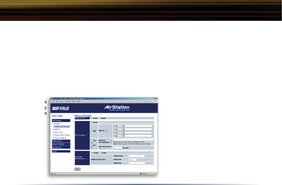
Wireless LAN Security
Broadcast SSID - You may Enable
or Disable broadcasting the SSID.
If denied, the AirStation will not be
Advanced Settings
Wireless
Security
Settings
Wireless
Security
Settings

29
found unless the specific AirStation’s SSID is entered in the client computer manually.
Data Encryption - Disable to have no encryption of the wireless data. This will make accessing
the AirStation and the network very easy. It is important to note that without encryption, it’s easy for
strangers to connect to your network, especially if your AirStation is broadcasting its SSID.
Select the type of data encryption:
• Disabled - Disable data encryption.
- WEP - Uses WEP encryption. Encryption key should be entered.
- TKIP - Uses TKIP (Temporal Key Integrity Protocol) for data encryption.
The encryption key is renewed every “Re-key interval” when “TKIP” is selected.
WEP - When the WEP (Wired Equivalent Protection) encryption standard is implemented into a
wireless network, a WEP key is used between the client and access point to encrypt, transmit, and
decrypt data. For this reason, the same WEP key must be used for communication between the
client and the AirStation.
An access point and client may both carry multiple WEP keys. It is necessary for not only the WEP
keys to match, but also the WEP key’s order. If a wireless client cannot support multiple WEP keys,
the AirStations must be configured to transmit key number 1 for a connection to take place.
Examples of WEP key:
64-bit ASCII: 5 digits of alphanumeric characters, “ab34Y”
128-bit ASCII: 13 digits of alphanumeric characters, “123456abcdef7”
Advanced Settings

30
■ Note: ASCII WEP keys are case sensitive.
64-bit HEX: 10 digits, using characters 0-9 and a-f, “00234ABCDE”
128-bit HEX: 26 digits, using characters 0-9 and a-f, “20123456789abcdeabcdeabcde”
TKIP - TKIP (Temporal Key Integrity Protocol) is a WEP expanded encryption technique. TKIP has
greatly improved WEP’s weaknesses by rotating secret keys between every packet. TKIP uses
WPA-PSK (pre-Shared Key).
Characteristics:
- The Initialization Vector is expanded from 24-bits to 48-bits.
- The Initialization Vector is randomized.
- Uses a different RC4 key for every packet.
AES - AES further improves TKIP by using AES (Advanced Encryption Standard) encryption meth-
od. With its hardware co-processor, AES is able to use some of the strongest encryption available
without sacrificing throughput as WEP and TKIP do.
TKIP & AES require an 8 to 63 character passphrase in ASCII or a 64 digit hexadecimal key.
Example 1: [ airstation -WPA-PSK ]
Example 2: [0123456789abcdef0123456789abcdef0123456789abcdef0123456789abcdef]
WPA Group Rekey Interval - When TKIP is selected, the encryption key is renewed at this inter-
val. This interval is in seconds; the range of acceptable values is 0-3600.
If 0 is entered, the key is never renewed.
Advanced Settings

31
IEEE802.1x/EAP authentication (WPA) - Configure Authentication and WPA Settings.
Disable - Do not use any RADIUS Server based authentication.
Enable - Authorized clients access this AirStation via a RADIUS Server.
Use 802.1x/EAP to authorize every wireless client who wants to access the AirStation by using
802.1x/EAP and a RADIUS Server. The RADIUS server provides login information for every user
establishing a more secure system than TKIP or other fixed encryption key methods. This also
reduces the amount of necessary key maintenance.
A RADIUS server is necessary for IEEE802.1x/EAP authentication. Enter [RADIUS Server], {RA-
DIUS Port] and [RADIUS Key] information.
RADIUS authentication:
RADIUS Server - Enter RADIUS server IP address.
RADIUS Port - Enter port number for authentication.
RADIUS Key - Encryption key between RADIUS Sever and the AirStation. Enter the same key as
registered in the server. Use a 1 to 256 character alphanumeric code.
Advanced Settings
32
■ Note: The lower the rekey
interval, the more often a rekey
occurs. Setting a low rekey in-
terval may affect performance
negatively.
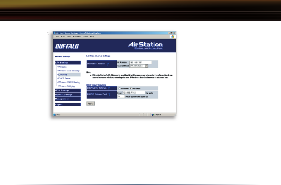
LAN Port
Set the LAN side Ethernet
settings.
LAN Side IP Address - Allows
ad min is tra tor to specify a static
IP and Subnet Mask for the
LAN side of the AirStation.
■ Note: If the AirStation’s IP
address is changed, the confi guring computer’s IP must be changed to the same range to continue
confi guration. If the LAN IP is changed, restart the AirStation. (Section 4.4.10). If the IP address is
changed, then the DHCP scope must be changed to match.
DHCP Server Function - Allows administrator to enable/disable the DHCP server function for the
AirStation LAN side. Select Use to enable and Do not use to disable the function. Once Use is
selected, the assigned IP address range can be specifi ed. Enter the starting LAN IP address and
total number of computers the DHCP server can accomidate.
■ Note: If there is another DHCP server on the network, one either must be disabled or the IP
LAN Port
Settings
LAN Port
Settings
Advanced Settings
33
range must be changed to
avoid confl icts derived from
overlapping DHCP scopes.
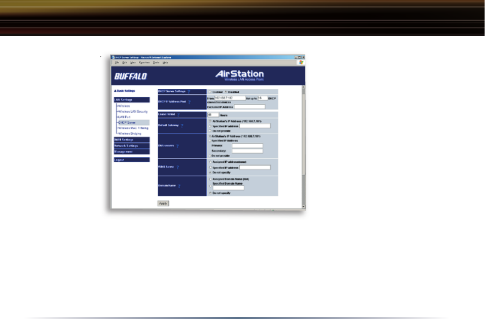
DHCP Server
this section Allows a more
advanced confi guration of the
DHCP server functions.
DHCP Server Function - Al-
lows ad min is tra tor to enable/
disable the DHCP server func-
tion for the AirStation LAN side.
Select Use to enable or Do not
use to disable this function.
If DHCP is enabled, wireless
and wired clients may receive IP addresses and other network information from the AirStation. If
the DHCP server is turned off, all client PC’s must have unique, static IP addresses and valid
network settings manually entered. Check with your LAN administrator for static IP information.
Assigned IP address (Range As sign ment) - Sets the beginning address and range of addresses
to be assigned by the AirStation’s DHCP server function. Select up to 253 consecutive addresses
(nodes). The IPs to be excluded from the range spec i fi ca tion should be entered in the specifi ed
fi eld.
DHCP Server
Settings
DHCP Server
Settings
Advanced Settings

34
Lease duration - Specifies the time in hours (1-999) that an assigned IP address is valid. If the cli-
ent computer does not request a renewal of IP address before the lease period expires, the AirSta-
tion can issue the IP to another client computer.
Default Gateway - Allows administrator to use the Default Gateway address (the AirStation’s IP
address), assign a specific Gateway address, or block clients from Gateway notification.
DNS server - Allows administrator to use the default DNS address (the AirStation’s IP address),
assign specific DNS addresses, or block clients from DNS address notification.
WINS server - Allows administrator to use a WINS address. Select auto assignment of the IP ad-
dress, enter a specific WINS IP address, or block clients from the WINS address notification.
Domain name - Allows administrator to use an assigned domain name, assign a specific domain
name, or block clients from domain name notification. Domain names will be sent to LAN comput-
ers when an IP address is assigned. Enter a maximum of 64 alphanumeric characters.
Advanced Settings
35
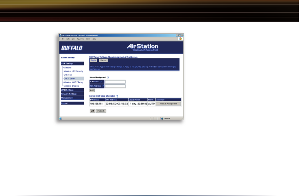
Manual IP and MAC Address
As sign ment - Allows administra-
tor to add additional leased IP
addresses tied to a specifi c MAC
address. When a specifi c MAC
address connects to the AP, the
IP address specifi ed will be given
to that client.
Display/Delete lease infor-
mation - IP addresses, MAC
addresses, lease periods and
status are displayed here.
Manual IP
and MAC
Address
Assignment
Settings
Advanced Settings
36
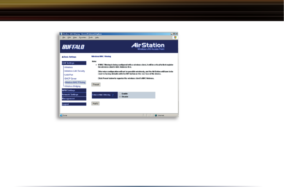
Wireless MAC Filter
Wireless PC’s Connection
- Select Enable to restrict
wireless connections to the
registered adapters in the list.
Select Disable to disable MAC
address fi ltering.
Press the Preset button
to enter the MAC Address
registration menus. This is
where MAC Addresses can be
assigned and deleted.
Wireless MAC
Filter
Advanced Settings
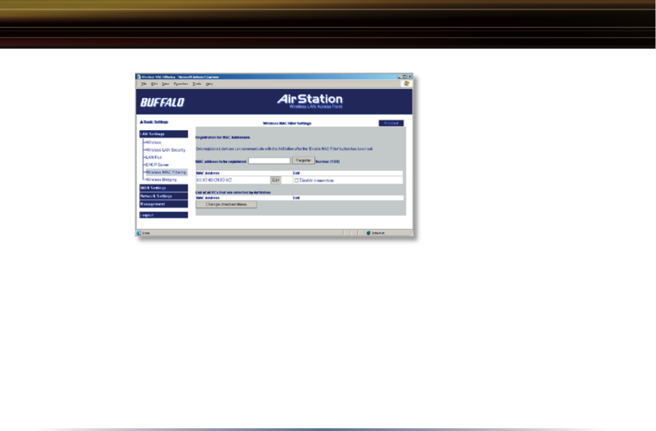
37
Registration for MAC Ad-
dresses - Input the MAC
addresses that are allowed to
communicate with the AirSta-
tion.
MAC address list - Displays
a list of all MAC addresses al-
lowed to communicate with the
AirStation.
Advanced Settings
Register for
Allowable PC’s
MAC Address
38
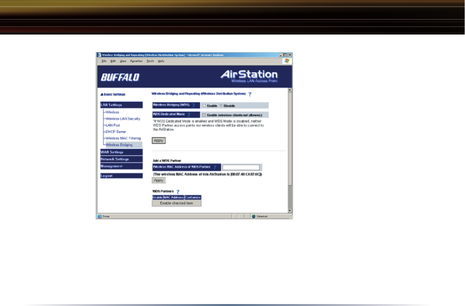
Wireless Bridge (WDS)
The Wireless Distribution
System supports peer-to-peer
AP communication.
Wireless Bridge (WDS) Func-
tion - Select Enable to allow
Bridge (WDS) mode between
AirStations or Disable to
block communication between
AirStations.
Wireless Bridge (WDS) dedi-
cated mode - Select Enable to
restrict wireless computer com-
munication with the AirStation.
In dedicated mode wireless
clients CANNOT connect to
WDS AirStations.
■ Note: All AirStations must support WDS and be on the same channel. Do not use ‘Auto-Channel’
when using WDS. For roaming support, use the same SSID on all devices.
Add a WDS Partnet - Allows administrator to input the wireless MAC address of AirStations for
Bridge (WDS) communication. The wireless MAC address is found in the Management section:
click on System Information, then the Wireless MAC Address label.
Advanced Settings
Wireless
Bridge (WDS)
Settings
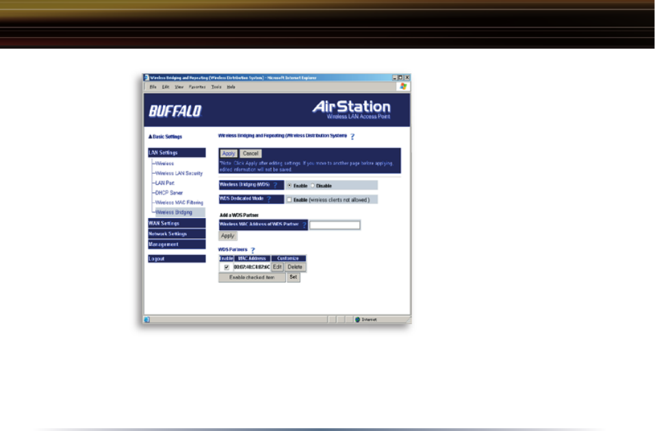
39
To enable WDS, set the Wire-
less Bridge (WDS) function to
Enable.
Enter the Wireless MAC ad-
dress of the AirStation to com-
municate with in the form of
pairs of characters separated
by colons and click Add.
Example of MAC Address:
00:00:00:00:00:00
Up to six AirStation MAC ad-
dresses may be registered.
Click Apply under Wireless
Bridge (WDS) settings when
the wireless Mac addresses
AirStation are entered.
Repeat this process on every other AirStation used in Bridge (WDS) mode.
Wireless
Bridge (WDS)
Settings
Advanced Settings
40
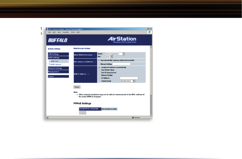
WAN Settings
Wired WAN Performance
- Select port speed and type of
duplex connecting to the WAN
port. If unknown, select Auto
negotiation.
MAC Address of WAN - Set
the AirStation MAC address to
be used for WAN com mu ni c-
a tion. Some ISP’s may require
you to set the MAC Address of
the WAN to be the same as the
MAC address of your broad-
band modem.
WAN IP Address - Allows
administrator to select DHCP
server, PPPoE, or manual set-
ting for the WAN port of the AirStation.
Auto IP assignment from DHCP server - acquire the IP address automatically from the DHCP
server.
Use PPPoE client - If selected, the in for ma tion listed below must be entered.
Advanced Settings
WAN port
Setup
WAN port
Setup

41
Manual setting - Enter the appropriate IP address and subnet mask.
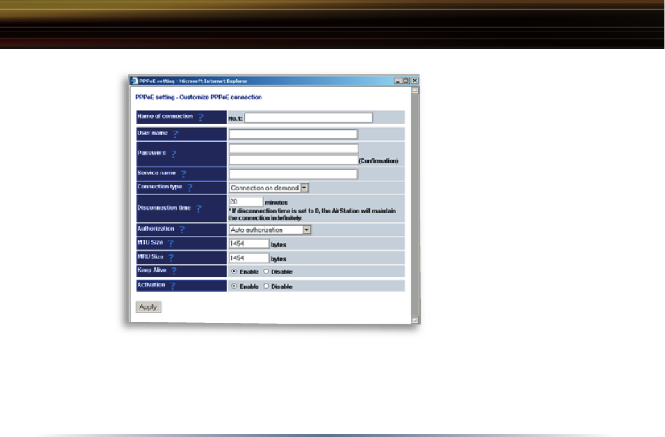
PPPoE Setting (for enabling PPPoE Client function) - Allows administrator to use PPPoE as
specified by the ISP.
The following parameters should be entered for PPPoE Settings:
Name of Connection - Enter the name of your connection.
User Name - Enter the user name (up to 64 alphanumeric characters) for PPPoE authorization.
Password - Enter the password provided by your ISP (up to 64 alphanumeric characters). Reenter
the password in the Confirmation box.
Service Name - Enter the PPPoE service name (up to 64 alphanumeric characters). If your ISP
doesn’t require a service name, then leave it blank.
Connection Type - Select from:
- Continuous Connection - connects immediately after setting and never disconnects.
- Connect on Demand - Reconnects when the disconnect time elapses.
- Manual - Disables Automatic Connection. Connects to the Internet using the connect button on
the initial settings page.
The Enter New Connection button will not appear until Use PPPoE Client is set.
Disconnection Time - Specify the number of minutes (0-1440) before automatic disconnect is
performed. If “0” is entered, the disconnect function is disabled. If Continuous Connection is
selected, the timer is disabled.
Advanced Settings
42
Authorization - Enter autho-
rization method for accessing
the ISP’s PPPoE server. If
unknown, select Auto authori-
zation.
MTU (Maximum Transmit
Unit) Size - Sets Maximum
Transmit Unit size (578-1492)
when using PPPoE.
MRU (Maximum Receive
Unit) Size - Sets Maximum
Receive Unit size (578-1492)
when using PPPoE.
Keep Alive - Enables the
PPPoE client to send a Link
Control Protocol (LCP) echo
request to the PPPoE server once per minute. If there is no reply within six minutes, the client
disconnects. Set to Disable if frequent disconnection occurs.
Activation - Enable/disable registered connection settings. If disabled, the connection is not per-
mitted.
PPPoE
Settings
Screen
Advanced Settings
43
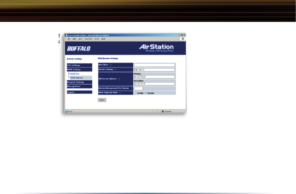
WAN Network
WAN side (Internet) param-
eters. These settings are gen-
erally not required if your ISP
is providing DHCP services. In
this case these fi elds can be
left blank.
Host Name - Enter the host
name.
Default Gateway - A default
gateway IP should be assigned
to the AirStation. If unknown,
leave blank. If Auto IP
as sign ment from DHCP Server is selected in the WAN Port section, a gateway IP is assigned
automatically, provided the DHCP server is confi gured to provide one.
DNS Server Address - Enter the primary and secondary DNS address(es) of the server to be used
by the AirStation for DNS resolution.
If DNS was set to Disabled, leave blank. If Auto IP as sign ment from DHCP Server was select-
ed, DNS addresses are assigned automatically, provided the DHCP server is confi gured to provide
them.
Network of
WAN
Network of
WAN
Advanced Settings

44
Remote Management Port Number - Set a specific port number when remote setup of the AirSta-
tion is planned. Using port 80 allows the AirStation to be accessed from the internet by connecting
to http://xxx.xxx.xxx.xxx (where xxx.xxx.xxx.xxx is your WAN IP address).
Block Ping from WAN - Allows a PING test from the WAN/Internet. Select Disable or Enable.
Advanced Settings
45
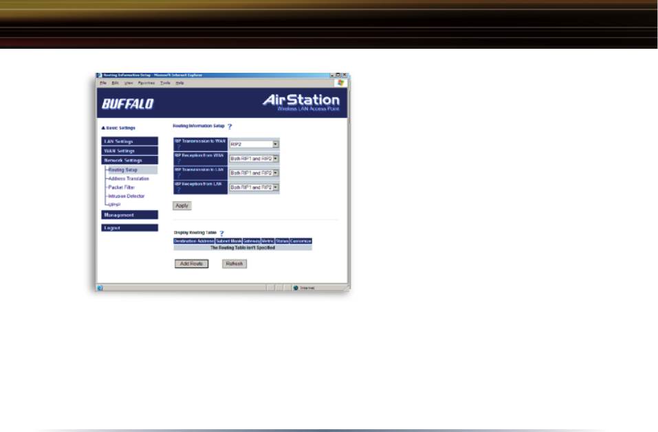
Network Settings
Routing Setup
RIP transmission to WAN - Allows RIP
transmission or None (no RIP) to WAN
RIP reception from WAN - Allows RIP
reception or None (no RIP) from WAN
RIP transmission to LAN - Allows RIP
transmission or None (no RIP) to LAN
RIP reception from LAN - Allows RIP
reception or None (no RIP) from LAN
RIP transmission to WAN - Allows RIP
transmission or None (no RIP) to WAN
Display current information - Allows
administrator to view and delete routing
information.
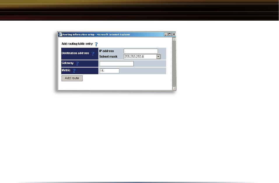
Click Add Route to Add a Routing Table Entry
•Destination address - Network IP address and subnet mask.
• Gateway - Address through which the packet passes before it reaches the des ti na tion address.
Routing
Setup
Advanced Settings
46
• Metric - Number of routers
(1-15) to be passed before the
packet reaches its destination.
Add Routing
Table Entry
Advanced Settings
47
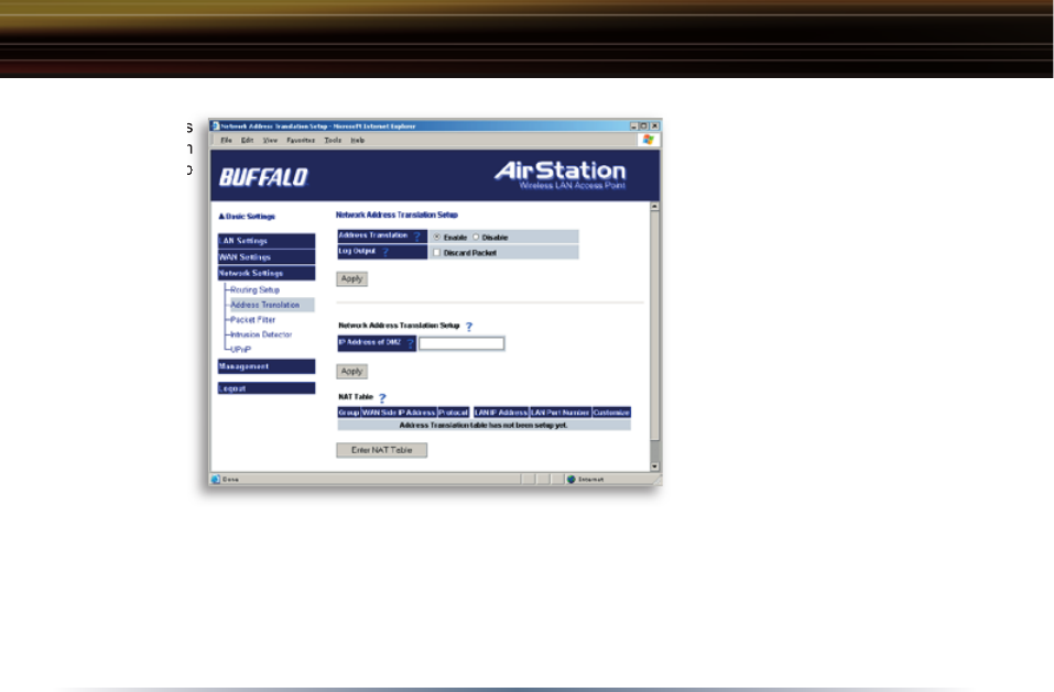
Address Translation
Select Enable or Disable.
Address Translation must be
enabled for client computers
to connect to the Internet.
Selecting Enable enables the
following functions:
• IP Masquerade - When the
LAN computer connects to the
WAN side, the IP address of
LAN computer is dynamically
translated to become the WAN
IP address of the AirStation.
Multiple LAN computers can
share one WAN IP address to
access the Internet.
• Static IP address transla-
tion -When the WAN requests
connection to the LAN, the WAN IP address of the AirStation is translated into the IP address
of the LAN computer.
Log Output - Set ‘Log Output’ to log discarded packets. Otherwise, a dropped packed is not
logged.
Address
Translation
Setup
Address
Translation
Setup
Advanced Settings
48
IPSec Pass-Through - Enables the AirStation’s ability to pass IPSec VPN data.
IP Address of DMZ - Allows administrator to set the DMZ (De-Militarized Zone) address. Incoming
packets containing no recognizable destination port information will be re di rect ed to the DMZ’s IP
address.
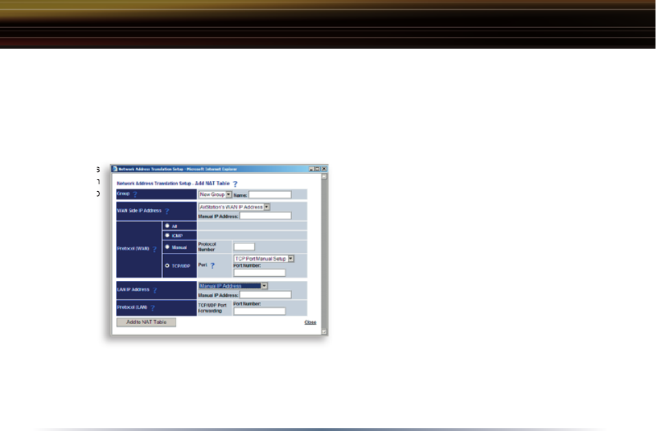
Display/Delete NAT Table - Allows ad min is tra tor to delete NAT tables.
Add NAT Table
Group - Specify a group (up to 16 characters)
that the NAT rule belongs to. Groups are
simply used to visually organize the NAT table
for the administrator. It is recommended that
you name each group after the protocol that is
being setup (e.g. Group Name FTP when set-
ting up address translation for FTP).
Click New Group to create new group or
select an existing group to add a NAT rule to it.
WAN Side IP Address - Select AirStation’s
WAN Side IP Address or Manual IP Ad-
dress. For Manual setting, enter the IP address used by the WAN computer to connect to the local
computer.
Advanced Settings
Address
Translation
Setup
Address
Translation
Setup

49
AirStation’s IP Address of WAN should be used unless you have multiple WAN side IP
addresses. Some network applications (including online games and streaming software) require
adding Address Translation tables; consult the software’s documentation for port information.
Protocol (WAN):
• All - Selects all IP protocols.
• ICMP - Network Diagnostic Protocol (1).
• Manual - Specify the protocol number (0-65535).
• TCP/UDP - Enter port number for TCP or UDP protocols. If both TCP and UDP are required,
then separate entries are required.
LAN IP Address - Select Manual IP Address and enter the destination IP address of the LAN
computer; or select AirStation’s LAN IP Address.
Protocol (LAN) - Enter the destination port number. If left blank, the packets are transferred to
the same port number as the source port number. Typically the destination port should be left the
same as the source port.
• Click Add to NAT table. This will add the information to the NAT table. Once you have gone
through this process for every desired translation, you will need to press the Apply button on the
top of the screen to start the translating.
Advanced Settings
50
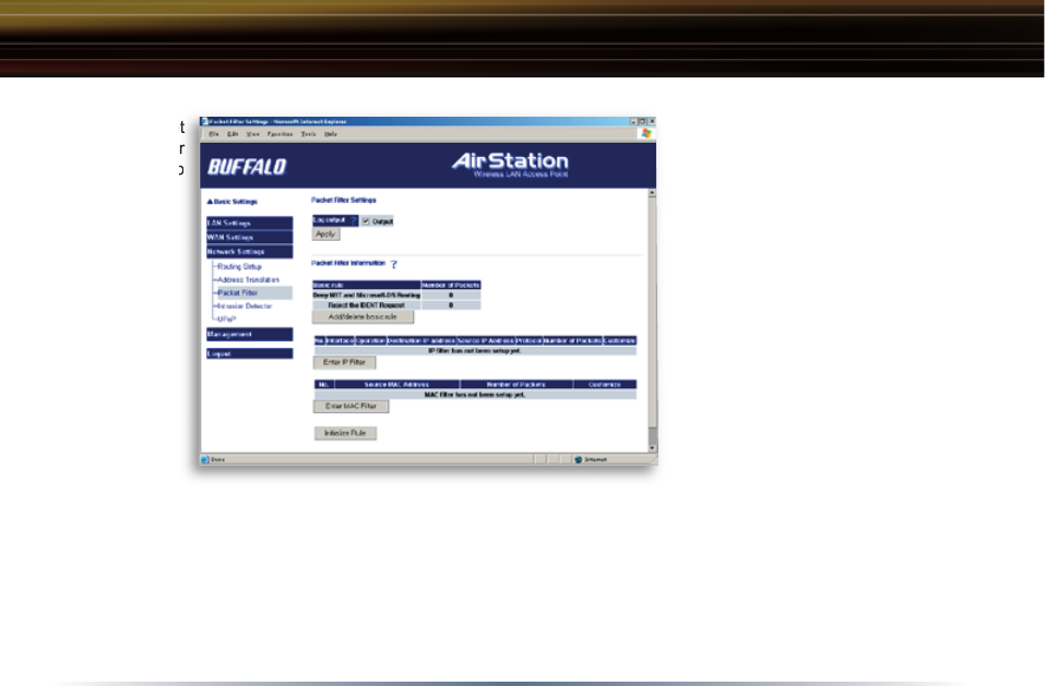
Packet Filter
Log Output - Select Output to
activate the packet fi lter log.
Packet Filter Information
- Click add/delete basic rule.
Place a check mark next to the
basic rule to enable.
Prohibit setup from wireless
LAN - Prohibits administration
from a wireless computer.
Prohibit setup from wired
LAN - Prohibits administration
from a wired computer.
Prohibit setup via wireless
bridge access point - Prohib-
its setup from a personal computer connected to another AirStation in a wireless bridge.
Prohibit NBT and Microsoft-DS routing - Prevent unexpected external access via Microsoft
network sharing. This prohibits computers on the internet from accessing shared resources on
Windows machines. It is recommended that you leave this fi lter activated.
Reject the IDENT request - The AirStation sends reject packets if it receives an IDENT request.
Use this fi lter when the communication speed goes down using a network application like E-mail,
Packet
Filter
Setup
Packet
Filter
Setup
Advanced Settings