BUFFALO 09101457-0 Wireless LAN Router User Manual WZR HP Manual indd
BUFFALO INC. Wireless LAN Router WZR HP Manual indd
UserManual.wiki
>
BUFFALO
>
09101457-0 User Manual
>
User manual part 1
Contents
1.
User manual part 1
2.
User manual part 2
User manual part 1
Navigation menu
Upload a User Manual
Namespaces
Wiki Guide
HTML
PDF
Info
Views
User Manual
Discussion / Help
Navigation
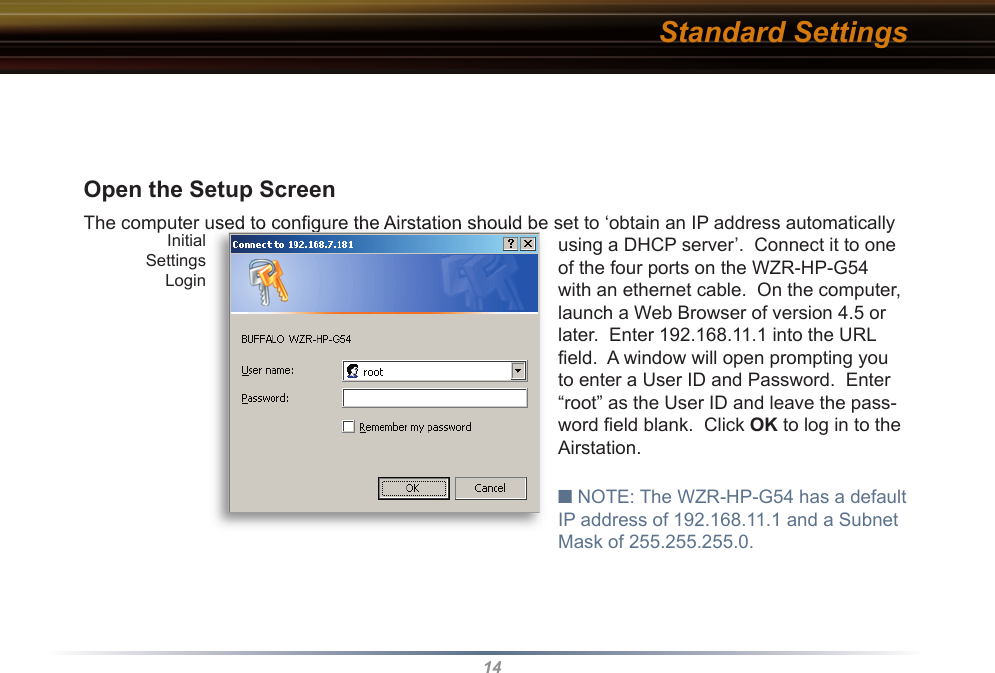
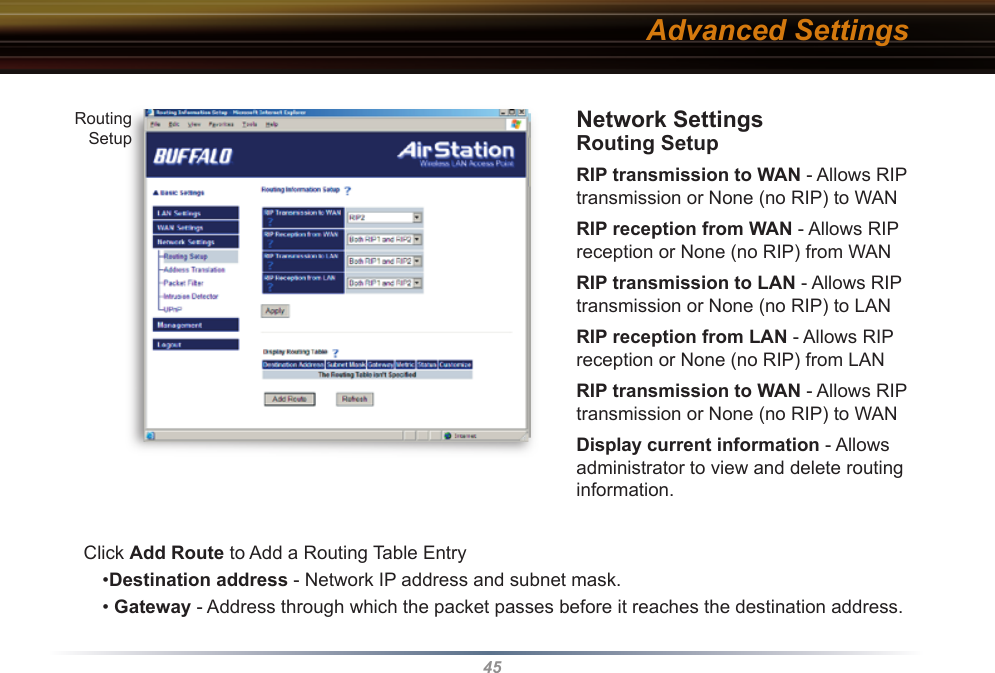
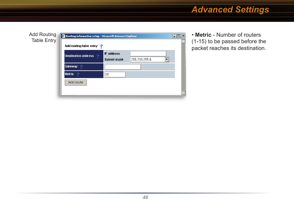
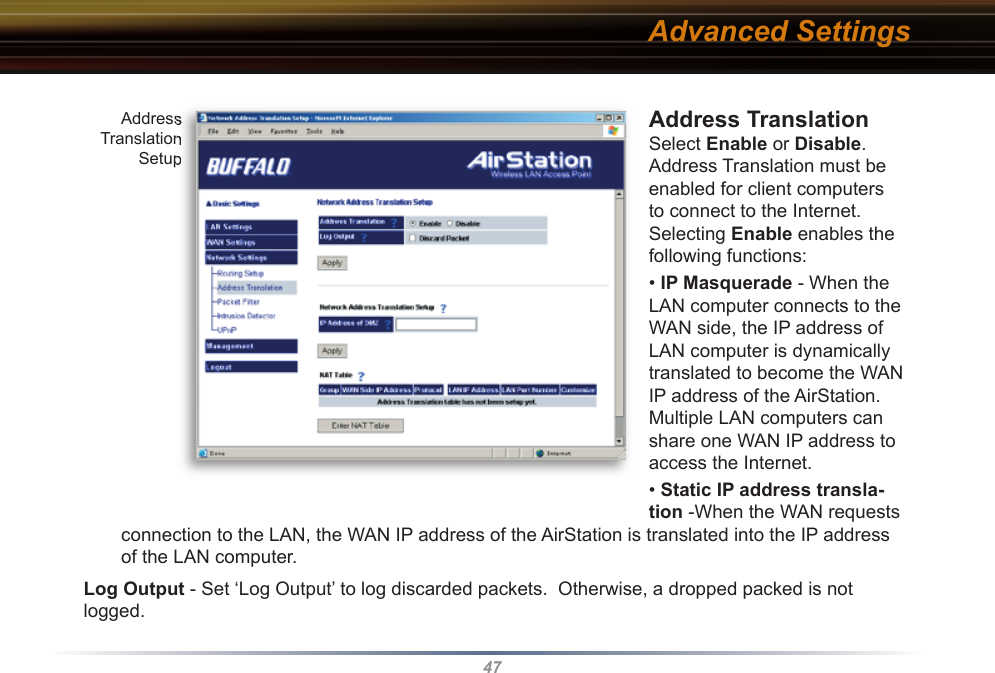
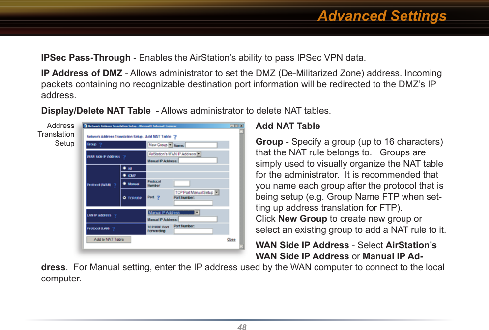
![30■ Note: ASCII WEP keys are case sensitive.64-bit HEX: 10 digits, using characters 0-9 and a-f, “00234ABCDE”128-bit HEX: 26 digits, using characters 0-9 and a-f, “20123456789abcdeabcdeabcde” TKIP - TKIP (Temporal Key Integrity Protocol) is a WEP expanded encryption technique. TKIP has greatly improved WEP’s weaknesses by rotating secret keys between every packet. TKIP uses WPA-PSK (pre-Shared Key).Characteristics: - The Initialization Vector is expanded from 24-bits to 48-bits. - The Initialization Vector is randomized. - Uses a different RC4 key for every packet. AES - AES further improves TKIP by using AES (Advanced Encryption Standard) encryption meth-od. With its hardware co-processor, AES is able to use some of the strongest encryption available without sacrificing throughput as WEP and TKIP do.TKIP & AES require an 8 to 63 character passphrase in ASCII or a 64 digit hexadecimal key. Example 1: [ airstation -WPA-PSK ]Example 2: [0123456789abcdef0123456789abcdef0123456789abcdef0123456789abcdef]WPA Group Rekey Interval - When TKIP is selected, the encryption key is renewed at this inter-val. This interval is in seconds; the range of acceptable values is 0-3600. If 0 is entered, the key is never renewed. Advanced Settings](https://usermanual.wiki/BUFFALO/09101457-0.User-manual-part-1/User-Guide-554643-Page-31.png)
![31IEEE802.1x/EAP authentication (WPA) - Configure Authentication and WPA Settings. Disable - Do not use any RADIUS Server based authentication.Enable - Authorized clients access this AirStation via a RADIUS Server.Use 802.1x/EAP to authorize every wireless client who wants to access the AirStation by using 802.1x/EAP and a RADIUS Server. The RADIUS server provides login information for every user establishing a more secure system than TKIP or other fixed encryption key methods. This also reduces the amount of necessary key maintenance. A RADIUS server is necessary for IEEE802.1x/EAP authentication. Enter [RADIUS Server], {RA-DIUS Port] and [RADIUS Key] information. RADIUS authentication: RADIUS Server - Enter RADIUS server IP address. RADIUS Port - Enter port number for authentication. RADIUS Key - Encryption key between RADIUS Sever and the AirStation. Enter the same key as registered in the server. Use a 1 to 256 character alphanumeric code. Advanced Settings](https://usermanual.wiki/BUFFALO/09101457-0.User-manual-part-1/User-Guide-554643-Page-32.png)